

PEERLESS SERIES WV-DV, WV-DV-03-075, WV-DV-03-085, WV-DV-03-110 Installation, Operation & Maintenance Manual
Page 1
Boilers
Installation,
Operation Et
Maintenance
Manual
PEERLESS _
CAST IRON BOILERS
Page 2
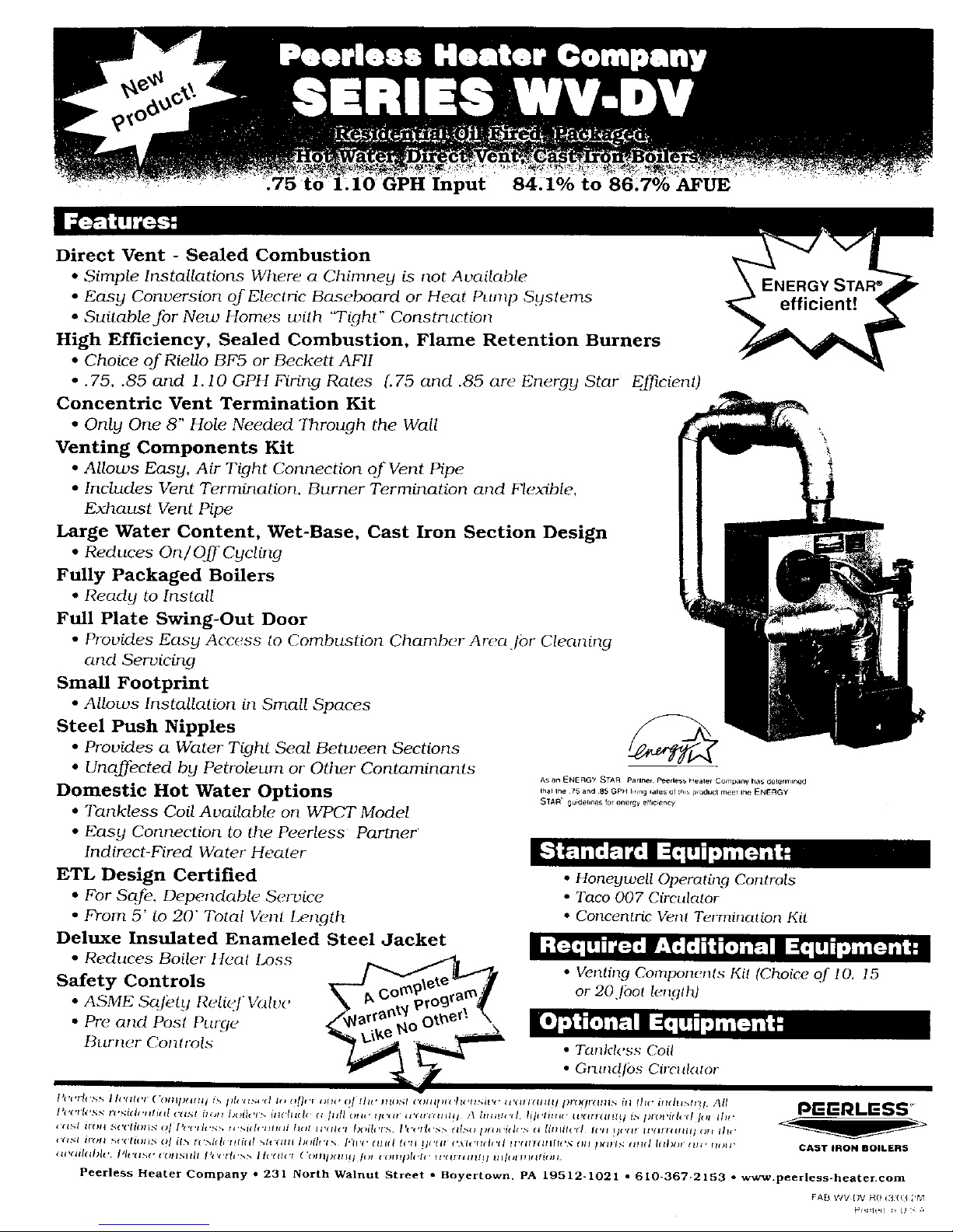
Input 84,1% to , AFUE
Direct Vent - Sealed Combustion
• Simple Installations Where a Chimney is not Available
• Easy Conversion of Electric Bas(#Joard or Heat Punlp Systems
* Suitable for New Homes with 'Tight" Constrttctior_
High Efficiency, Sealed Combustion, Flame Retention Burners
• Choice ofRiello BF5 or Beckett AFII
• .75, .85 and I. 10 GPft Firing Rates {.75 arid .85 are Energy Star Ej'_cient)
Concentric Vent Termination Kit
• Only One 8" Hole Needed Through the Wall
Venting Components Kit
• Allows Easy, Air Tight Connection of Vent Pipe
• Includes Vent Termination, Burner Termination and Flexible,
Exhaust Vent Pipe
Large Water Content, WetBase, Cast Iron Section Design
• Reduces On/Oj]'Cycling
Fully Packaged Boilers
• Ready to Install
Full Plate Swing-Out Door
• Provides Easy Acc_ss to Combustion Chamber Arcajbr Cleaning
and Servicing
Small Footprint
• Allows Installation in Small Spaces
Steel Push Nipples
• Provides a Water Tight Seal Between Sections
• Unaffected by Petroleum or Other Contaminants
Domestic Hot Water Options
• Tankless Coil Available on WPCT Model
• Easy Connection to the P_.erless Partner
Indirect-Fired Water Healer
AS an _NEFIGY STAR Parlrle_ l:_earles_ Heale¢ Company has determlned
lhal lhe 75 and 85 GPH liriag fales of thls p_odvcE mee_ lhe KNERGY
STAR ¸¸ gu_(leh_S for energy erf_ency
ENERGY STAR ®
efficient!
• Venting Componenls Kil (Choice of 10. 15
or 20.]bol le_glh)
• Tankl('ss Coil
* Gnln_tlbs Circlll_m)r
FA[& WV DV R013 03 ;'#_1
Page 3
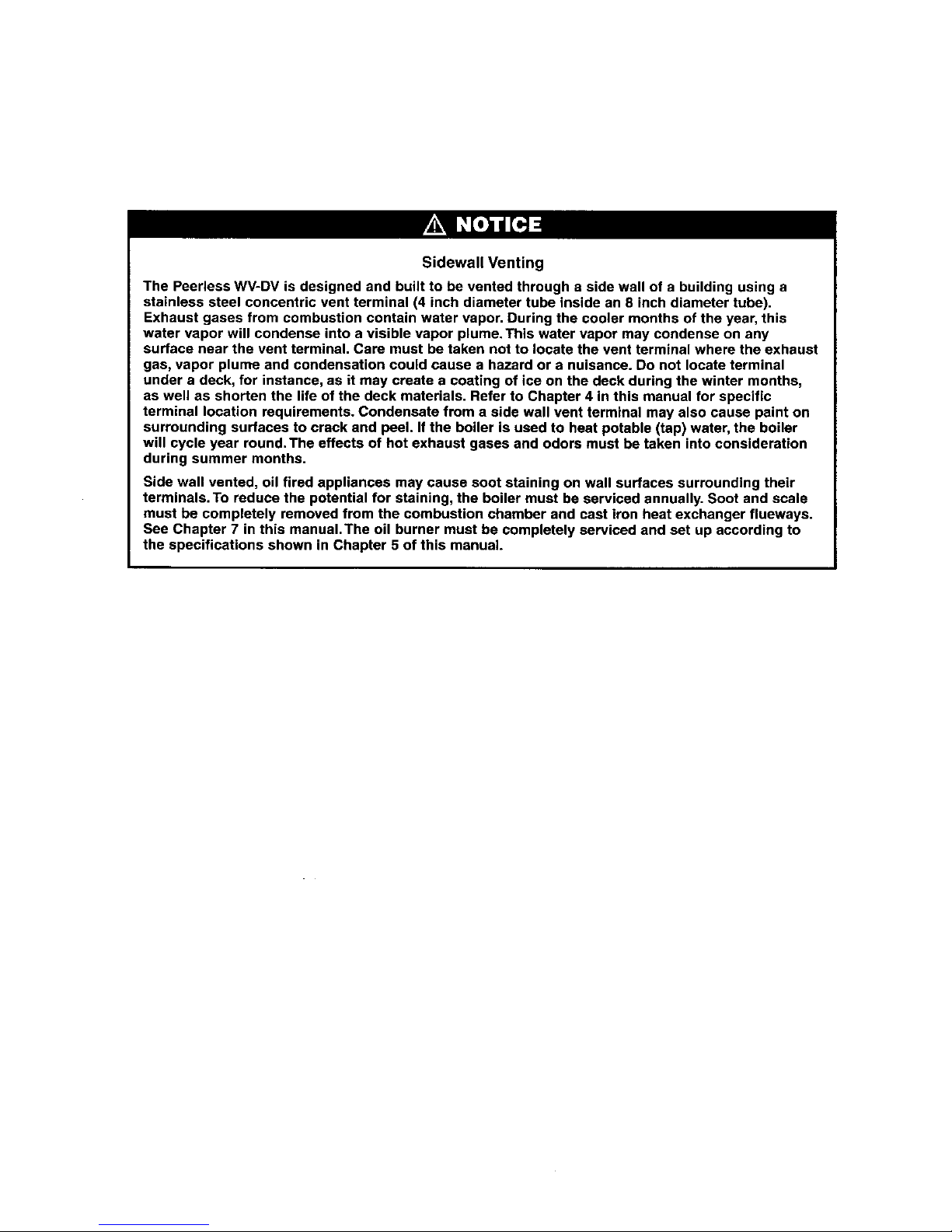
Sidewall Venting
The Peerless WV-DV is designed and built to be vented through a side wall of a building using a
stainless steel concentric vent terminal (4 inch diameter tube inside an 8 inch diameter tube).
Exhaust gases from combustion contain water vapor. During the cooler months of the year, this
water vapor will condense into a visible vapor plume. This water vapor may condense on any
surface near the vent terminal. Care must be taken not to locate the vent terminal where the exhaust
gas, vapor plume and condensation could cause a hazard or a nuisance. Do not locate terminal
under a deck, for instance, as it may create a coating of ice on the deck during the winter months,
as well as shorten the life of the deck materials. Refer to Chapter 4 in this manual for specific
terminal location requirements. Condensate from a side wall vent terminal may also cause paint on
surrounding surfaces to crack and peel. If the boiler is used to heat potable (tap) water, the boiler
will cycle year round.The effects of hot exhaust gases and odors must be taken into consideration
during summer months.
Side wall vented, oil fired appliances may cause soot staining on wall surfaces surrounding their
terminals. To reduce the potential for staining, the boiler must be serviced annually. Soot and scale
must be completely removed from the combustion chamber and cast iron heat exchanger flueways.
See Chapter 7 in this manual.The oil burner must be completely serviced and set up according to
the specifications shown in Chapter 5 of this manual.
Page 4
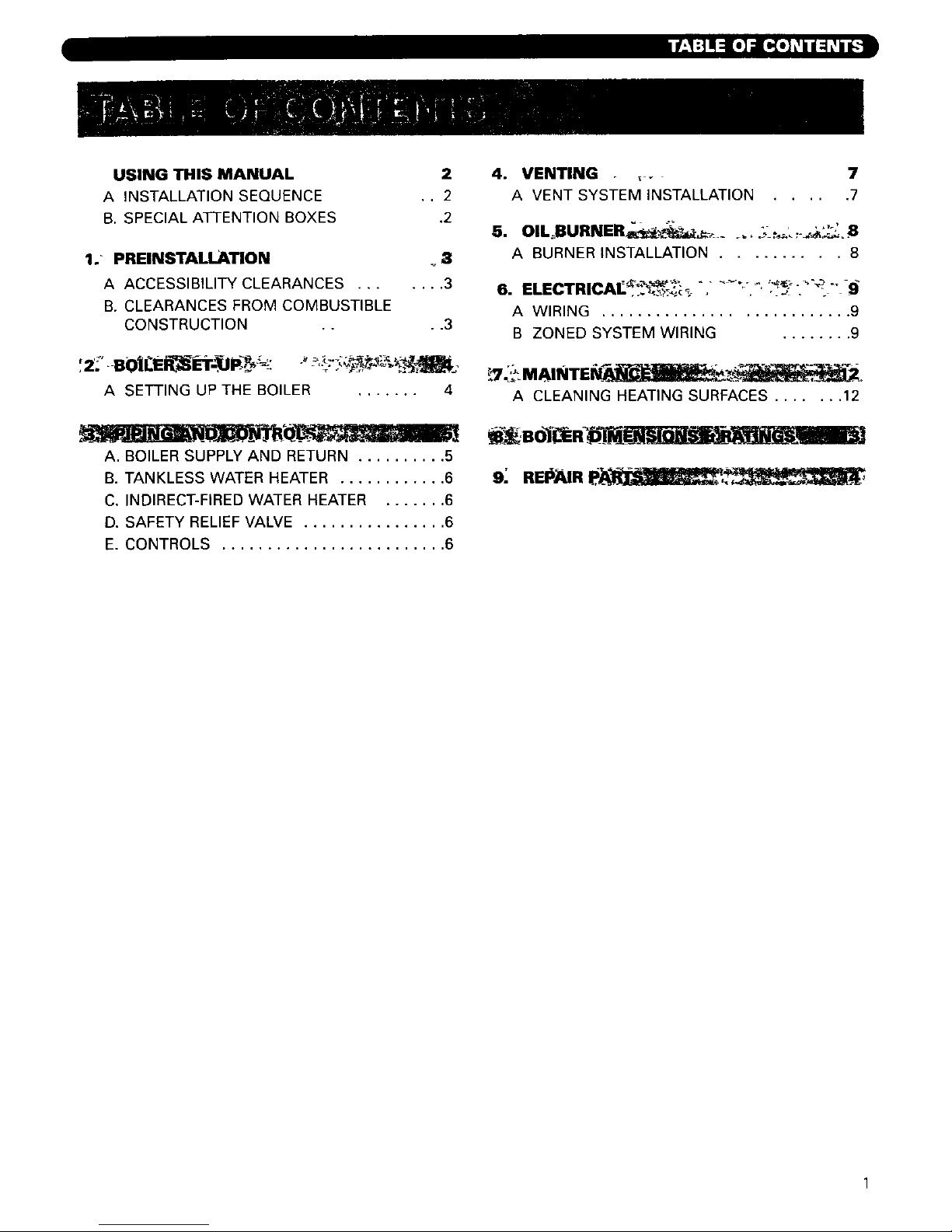
USING THIS MANUAL
A INSTALLATION SEQUENCE
B. SPECIAL ATTENTION BOXES
2
• . 2
.2
1.- PREINSTALLATION _.3
A ACCESSIBILITY CLEARANCES ....... 3
B. CLEARANCES FROM COMBUSTIBLE
CONSTRUCTION .... 3
A SETTING UP THE BOILER ....... 4
A. BOILER SUPPLY AND RETURN .......... 5
B. TANKLESS WATER HEATER ............ 6
C. INDIRECT-FIRED WATER HEATER ....... 6
D. SAFETY RELIEF VALVE ................ 6
E. CONTROLS ......................... 6
4. VENTING . :_ 7
A VENT SYSTEM INSTALLATION ..... 7
A BURNER INSTALLATION .......... 8
A WIRING ........................... 9
B ZONED SYSTEM WIRING ........ 9
A CLEANING HEATING SURFACES ....... 12
9; REI#_.IR P; - ,_ . .,
Page 5
l[_€-_ _vAT___LI_
_I Ih__'JIIr!l I If'-_l / [s] L'!Ik't :(el IJ _ _ [q
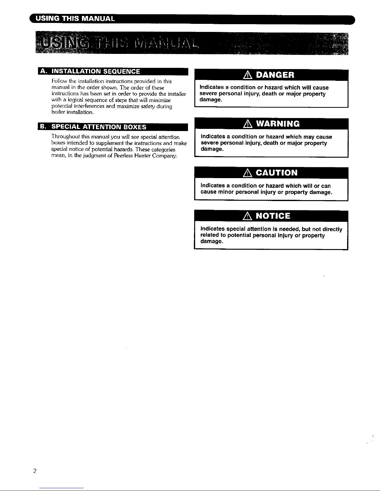
Follow the installation instructions provided in this
manual in the order shown. The order of these
instructions has been set in order to provide the installer
with a logical sequence of steps that will minimize
potential interferences and maximize safety during
boiler installation.
Indicates a condition or hazard which will cause
severe personal injury, death or major property
damage.
Throughout this manual you will see special attention
boxes intended to supplement the instructions and make
special notice of potential hazards. These categories
mean, in the judgment of Peerless Heater Company:
Indicates a condition or hazard which may cause
severe personal injury, death or major property
damage.
Indicates a condition or hazard which will or can
cause minor personal injury or property damage.
Indicates special attention is needed, but not directly
related to potential personal injury or property
damage.
Page 6
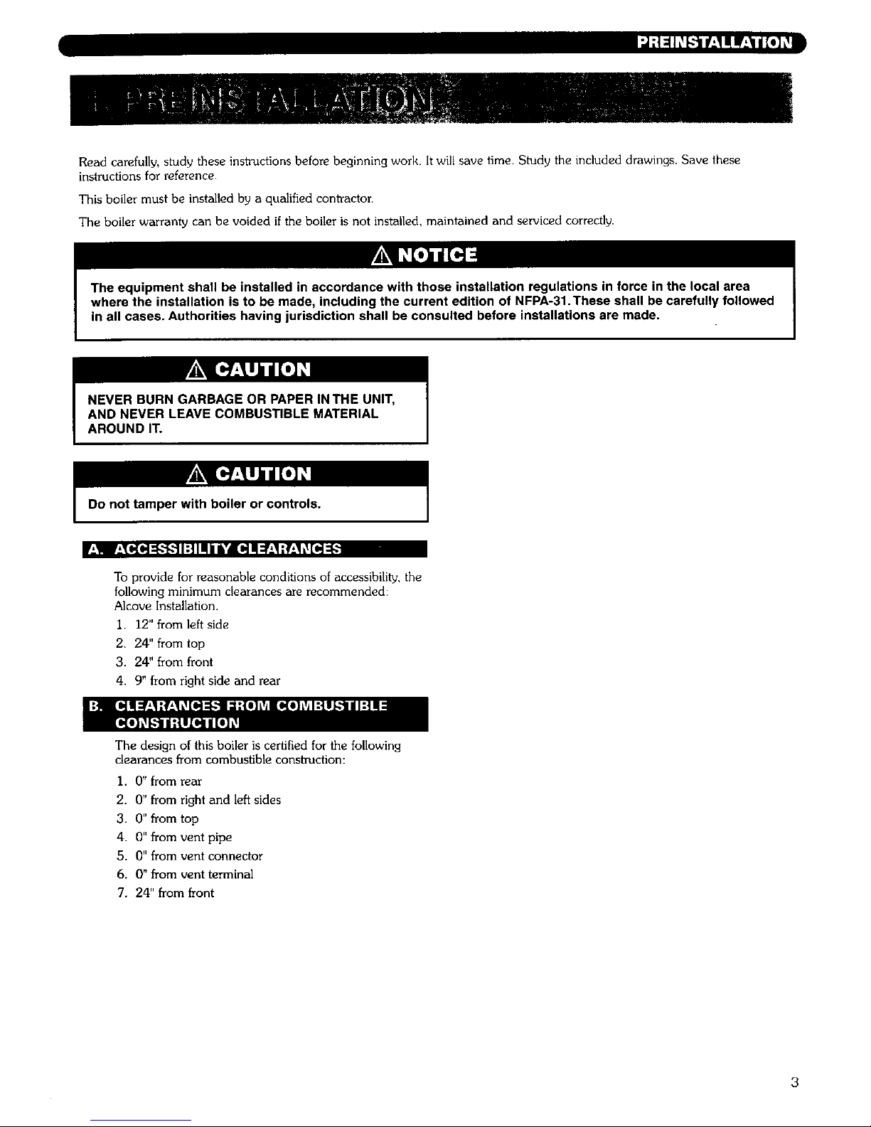
Read carefully, study these instrudions before beginning work. It will save time. Study the included drawings. Save these
instructions for reference.
This boiler must be installed by a qualified contTactor.
The boiler warranty can be voided if the boiler is not installed, maintained and serviced correctly.
in all cases. Authorities having jurisdiction shall be consulted before installations are made.
NEVER BURN GARBAGE OR PAPER IN THE UNIT,
AND NEVER LEAVE COMBUSTIBLE MATERIAL
AROUND IT.
Do not tamper with boiler or controls.
r_'! V,_T_IH :_"l 1:11I! / Ik'dl[P]I! =r'-_:_-'I _ [_] =_
To provide for reasonable conditions of accessibility, the
following minimum clearances are recommended:
Alcove Installation,
I. 12" from left side
2. 24" from top
3. 24" from front
4. 9" from right side and rear
The design of this boiler is certified for the following
clearances from combustible construction:
1. 0 _ from rear
2. 0" from right and left sides
3. 0" from top
4. 0" from vent pipe
5. 0" from vent connector
6. 0" from vent terminal
7. 24" from front
3
Page 7

V;I E-_:lill_,_[rlll'l: l:{e]l!:l:
I Prepare sketches and notes of the layout of the
installation. Include boiler location, venting system,
existing piping and wiring. Show existing equipment
that may interfere with installation of new
equipment. See Section 4-A. "Vent System
Installation," Page 7, and Figure 5.
2. Provide a level foundation, located as close as
possible to the center of the heating system.
3. This boiler is suitable for use on combustible
flooring, provided the boiler is not set on carpet and
a metal drip pan is placed under the appliance.
4.
See exploded view (Figure 11 on page 14). After
uncrating boiler and setting it on foundation, open
burner mounting plate (Item 5) and make certain the
target wall (item 2) is seated in the back of the
combustion chamber. Ceramic fiber blanket base
liner (Item 3) should be lying fiat on bottom of
combustion chamber between target wall and burner
mounting plate. Close burner mounting plate.
4
Page 8

I_I_ _[_ L'__1_ E_e]_o] _
_1 I:[o]lnn_;! _-"LmJ_1"]i_'m-'_L_lD]I:i:liLil;ik
1.
2.
3.
4.
5.
See Figure I for suggested piping to the boiler.
Make up cold water supply connection to the boiler.
Plug all open tappings in the boiler and fill with
water. Apply approximately thirty (30) psi pressure.
Check to make certain that all joints and fittings are
water tight.
After all joints and connections have been proven
water tight, remove cold water supply and plugs
from all tappings that are to be used. See page 13,
Figure 10 for tapping locations.
Relurn water piping must be done in such a manner
to allow clearance from the burner mounting plate to
the circulator stand pipe or other piping when
opening and closing the burner mounting plate.
Peerless Heater Company suggests using a 1-I/4"
tee, a 90 ° street elbow and 1-1/4" x 3-I/2" pipe
nipple in the return tapping before a vertical
circulator stand pipe is used as shown in Figure 10
on Page 13.
Figure 2
Note: If boiler is to be used in conjunction with a refrigeration
system, the chilled medium shall be piped in parallel with
boiler and proper valves applied to prevent the chilled
medium from entering the boiler. Refer to Figure 2.
When the boiler is connected to heating coils located in
air handling units, the boiler piping system must be
equipped with flow coni_ol valves or other automatic
devices to prevent gravity circulation of the boiler water
during the cooling cycle.
Figure 1
6. The supply and return connections should be sized to
suit the system. A I-1/2" to 1-1/4" reducing coupling
may be used on the return where the system piping is
1-1/2". The supply should be out of the top of the
back section and return to the bottom of the front
section. There is a 3/4" tapping in the top of the back
section for air eliminafion.
Page 9

Idl',,,,ll_[ F;I_ID][_o_]_!lu/;[o]_
pit _"f_,l'_:ilikl ;,1:111:1-_kVl±!IkVj:! i_:IL_IN I:k$1_Avlzli_;i r:l:1:li_-
HIGH TEMPERATURE
HOT
MIXED
WATI
HEATER
_/4" CONTROL
TAPPING
I. Remove safety relief valve and 3/4" x 3" nipple from
parts bag. Install nipple and safety relief valve in top
or rear tapping. See Figure 10, Page 13. If rear
tapping is used, installer must supply an elbow so
that safety relief valve is installed in vertical position.
MIN_
CONTROL
=l! [_e] L'_|II:To]I_
WATER
MIXER
COLD
INLET---
1. For complete information on servicing and
adjustment of controls, refer to the attached con_ol
specification sheets.
Figure 3
loW IIOID]IH:_e,I_q;II:t=ID] ltAlf,__ld=l:_I:l=r-'_ld=l;
I. If a water boiler is to be used in conjunction with an
indirect-fired water heater refer to Figure 4 for typical
piping. Also refer to additional instructions supplied
with tank.
TANK
THREE WAY
OOME:STIC HOT
WATER SUPPLY
t
SYSTEM
WATER
SUPP_
SYSTEM
BOILER
Figure 4
CIRCULATOR
INTERNAL
COIL
DOMESTIC HOT WATER
STORAGE TANK
Install mixing valve in hot water supply piping.Water
temperature above 125°F can cause severe burns
instantly or death from scalds.
Page 10

L
LvJd_._|gI_[€t
This boiler is shipped with a Flex-L International Vent
Terminal carton, and a Flex-L International Venting
Components Kit. The following components from
these two cartons must be used in the installation of
this boiler:
• CeraFlex Oil Vent Terminal
• CeraFlex Vent Pipe
• CeraFlex Appliance Adapter
• CeraFlexTerminal Adapter
• CeraFlex Sealant
This Oil-Fired Unit Shall be Connected to a Direct Vent
System, to Assure Safe Proper Operation of the Unit.
F__I |vJ_b._lI _.'t'I..lI_LVjI IO!--'IILIlIZlI[e]_
I. Determine vent terminallocation:
a. Vent length must be between 5' and 20' long. See
paragraph 3 and Figure 5 for air intake
requirements.
b. No clearance is required between vent terminal
and combustible construction.
c. Vent terminal extends 12" beyond outside wall
surface and at least 16" beyond inside wall
surface. See Figure 5.
d. Provide 3' clearance above any forced air inlet
within 10'.
e.
Provide 4' clearance below, 4' beside, or ]' above
any door, window, or gravity air inlet into any
building.
Provide 1' clearance between bottom of vent
terminal and ground level or between bottom of
vent terminal and normal snow lines.
g,
h,
i,
J,
Provide 4' horizontal clearance from, and in no
case above or below, unless a 4' horizontal
clearance is maintained, from electric meters, gas
meters, gas regulators, and gas relief equipment.
Provide 5 * clearance to the vent outlet of a fuel
oil supply tank.
Provide 1' clearance to the soffit of the roof and
3' clearance to an inside corner of an L-shaped
building.
Do not locate vent terminal over public walkways
where condensate could create a nuisance or
hazard.
k. When adjacent to a public walkway, locate vent
terminal at least 7' above grade.
2. Use FIex-L International Inc. 4" diameter CeraFlex
Vent Pipe.
Table 1
WALL
]]41CKNESS
1 "
2"
3"
4-"
5"
6" TO 14"
DIM.
A
21"
20"
19"
18"
-VENT PIPE MATERIAL: FLEX L INTERNATIONAL iNC.
4"¢ CERAFLEX VENT PIPE. LENGTH: 5' TO 20'
17" 12 !/2"_,_
16"
OUTER WALL_
PLATE
EXHAUST
ABOVE GROUND
OR NORMALLY
EXPECTEDSNOW
ACCUMULATIONLEVEL
TERMIN
_INNER
WALL
PLATE
INTAKE
CLAMP
(BY INSTALLER)
(SLOPING DOWN
TOWARDS TERMINAL)
MIN. 1/4" SLOPE/FOOT
:E ADAPTER
WITH TEST PORT
_AIR INTAKE MATERIAL: ALUMINUM
FLEX (SHOWN) 5' TO 30' OR GALVANIZED
SMOKE PIPE 5' TO 40' EQUIVALENT
,jrWV-DV
INTAKE CLAMP
(BY INSTALLER)
AIR ADAPTER
(RIELLO ONLY)
Figure 5: Venting
7
Page 11

3.
4.
For air intake, use 4" diameter galvanized smoke
pipe or 4" diameter flexible corrugated aluminum
pipe. Maximum equivalent length of galvanized
smoke pipe is 40'. A]Iow 5 equivalent feet for each
90 ° elbow used. (Example: No more than 20' straight
smoke pipe can be used with four 90 ° elbows.) To
connect air intake to Riello BF5 burner, use burner
air adapter from trim bag to connect 4" air intake to
3" opening on top of burner. See Figure 5.
To connect air intake to Beckett AFII burner, install
4" galvanized smoke pipe in the inlet ring on the
right side of the burner housing. Secure using sheet
metal screws and slots in inlet ring. See Figure 6.
For specific installation and maintenance instructions
for the Flex-L Vent Terminal, Appliance Adapter,
Terminal Adapter, Burner Air Adapter (Riello only),
and Sealant that are included with the boiler, as well
as instructions for installation of flexible vent pipe and
air intake pipe, refer to Flex-L Manual #Y4-CF12
included in vent kit.
4" GALVANIZED
SMOKE PIPE
(BY INSTALLER)
SECURE SMOKE PiPE
W/ SHEET METAL
SCREWS IN BLOTS
Figure 6: Beckett AFII Air Connection
Peerless requires that the vent slopes down 1!4" per
foot towards the vent terminal. This takes precedence
over the requirments show in the Flex-L manual.
Page 12

BURNONLY#2FUELOILINTHISAPPLIANCE.DO
NOTUSEGASOLINE,CRANKCASEDRAININGSOR
ANYOILCONTAININGGASOLINE.
V;. :{IJ ;| tH =1;!1 hH--'_l€;_ II W;'I / [e] L_
I The oil burner is supplied with a mounting flange
fixed in position.
2. BE SURE HI TEMP GASKET IS BETWEEN THE
BURNER MOUNTING FLANGE AND THE
COMBUSTION CHAMBER COVER PLATE.
3. Care must be taken when routing the oil lines so not
to interfere with the opening and closing of the
burner mounting plate. Flexible oil lines or flared
copper disconnects with valves (when copper lines
are used) may be installed to assure full opening of
the burner mounting plate when servicing.
4. Oil Burner Specifications:
For information pertinent to the oil burner such as
nozzle sizing, fuel supply piping, adjusting or
servicing, refer to the charts below and the burner
installation manual
5. Sampling tapping in CeraFlex Appliance Adapter
must be used for COz, smoke and flue pressure
readings.
6. Burner should start automatically when thermostat is
turned up and main boiler service switch is turned
on. If burner does not start, check to be sure there is
oil in the tank and push reset button on burner
control: (Beckett) square red button; (Riello) round
red button inside clear flexible cover on back of
burner coven If burner still does not start, contact
serviceman.
Do not attempt to start the burner when excess oil
has accumulated, when the unit is full of vapor, or
when the combustion chamber is very hot.
7. Burner and boiler can be shut down by turning down
the thermostat and moving the main boiler service
switch to the "off" position.
Always keep the manual fuel supply valve shut off
if the burner is shut down for an extended period
of time.
Table 2
Boiler Model No.
WV-DV-03-075
WV-DV-03-085
WV-DV-03-110
Riello BF5 Oil Burner
Delavan Nozzle Pump Pressure
Size (psig)
.60 80 ° B 165
.65 80 ° B 165
.90 80 ° B 165
Turbulator
Setting
1
1
2
Air Damper
Setting
3.3
3.8
5.0
Table 3
Boiler Model
No.
WV-DV-03-075
WV-DV-03-085
WV-DV-03-110
Beckett AFII 100 Burner
Nozzle Pump Pressure
Manufacturer, Size (psig)
Delavan .60 70 ° B 170
Hago .65 45° B 170
Delavan .85 60 ° B 170
Pin No.
3
4
6
Air Dial
Setting
4.25
5.5
6.5
Start-up and adjustment recommendations: Above Turbu[ator, Pin, Air Damper, and Air Dial settings are start-up settings
only. Adjust burner for highest CO2 (no more than ]3%) while maintaining a 0 smoke spot. Pressure or draft over fire and in
flue cannot be adjusted. HoweveT, draft and/or presstlre measurements must be taken in these two [oec3t[onsand recorded
for reference. AI_adjustments and measurements must be made using suitable instruments such as those found in a
Bacharaeh Combustion Test Kit
Page 13

l:m i',(o]_._I::1e]1,-"'5"4.."]1d:1L'JI lr*_lI "'11L'I[,::
L,! ivA_il;tIL_[_
I. All electrical wiring shall be done in accordance with
the National Electrical Code and Local
Requirements. Single Pole Switches including those
of Safety Controls or Protective Devices shall not be
wired in a grounded line.
1. Wire zone circulators as shown in Figure 9 and zone
valves as shown in Figure 10.
Removal of burner harness conduit clamp can allow
burner to be energized with burner mounting plate
open, creating a severe burn hazard to boiler
maintenance personnel.
Ugh; NJ. w*_ Muff co_pLy ul_ _ _ m_ _,_ I£OJLA_&
r:
SCqV,CE _a4T04
:--: °,,,,-.
...... 14 "*_LT _ (0Y mST_Li_)
- -
-- FORCED HOT WATER
R • _ L-- T WITH TANKLESS HEATER
w _ w _
I ...... r__ __, z:---;_ _=_ %. ,,,,,o,,
, _ -- _ ots_o_,l_ _
Y
• WITI,K_IT T_IO.r_S H,_"t ER
1
Figure 7: Primary Control
10
Page 14

Figure 8: Riello Burner With K7R Timer
AquA STAT RELAY
SWITCHING RELAY
H_S45A OR
w/_ - 829A-845
TV 0- .........
IWIRE REMAINDER OF CI
AqUASTAT RELAY IN C2
ACCORDANL:E WITH
Li
DtAGRAM SUPPUED) L2 _ --
120v- 60HZ
sw,
LINE VOLTAGE
J,,.Q_VOLTAGE
NOTE:
ALL WIRING MUST COMPLY WITH APPLICABLE
CODES, ORDINAiNCE S _AND REGULATIONS.
Figure 9: Zoning With Circulators
ZO.E", _
11
Page 15

I_ANSFORMER
120/24V-60HZ
120V-60HZ
TO MAIN
DISCONNECT
S_TCH
t
(HOT)
©
I I
F I
I I
TO THERMOSTAT I_F--
CONNECRON 1[
GRAY WIRES _j
LOCATED IN
BOILER JUNCTION
80X
- -- LOW VOLTAGE
-- LINE VOLTAGE
i L
I L
R I'
I
F
I
I
R I
I
I
I
I
I
÷
Y
NOTD
ALL WIRING MUST COMPLY WITH APPLICAi_LE CODES,
ORDINANCES, AND REGULATIONS
©
I
I
I
Figure 10: Zoning With Zone Valves
12
Page 16

4. Remove any scale or soot from the combustion
chamber area by vacuum cleaning or any other
available means.
Boiler is to be cleaned at least once a year. To
thoroughly clean the boiler it must be brushed
down from the top. Alternately, for limited space or
minimum clearance to combustible installations,
cleaning the heat exchanger from the combustion
chamber side is acceptable.
TO CLEAN:
1. Turn off all electrical power to the boiler before
beginning cleaning operation.
2. Remove top jacket panel and flue collector cover
plate, Item 11.
3. Brush the flue passages thoroughly from the top with
a wire brush. If unit is extremely dirty, brushing up
from the combustion chamber area also may be
necessary. The target wall is made of a soft ceramic
fiber. Care must be taken not to damage this material
during cleaning.
Combustion chamber cover plate must be opened
to facilitate this operation.
5. Replace oil burner and flue collector cover plate
making sure all gaskets are in place.
Combustion chamber and flue collector may be
under pressure when burner is running. Flue
collector cover plate and combustion chamber
must be completely sealed before boiler is returned
to operation.
6. Replace jacket top panel.
All Cover Plates, Enclosures, and Guards must be
maintained in place at all times, except during
maintenance and servicing.
13
Page 17

:T=]II::I ;] ¥]T_'d_=_ [--'1F-1[;_'__iT_[_[--"]
SAFELY RELIEF VALVE
OR AIR ELIMINATION _ _1
l
55"
_2 11/16'
5 1/_6"_ 7 1/16"
q_
%
\
x--SAFETY
VALVE
i _"* FLOOR LINE
_- ALTERNATE 3/4"
DRAIN VALVE
REAR
_15 3/41L,-
_22 1/8" --_
1 1/2" SUPPLY- 4"_,- 1
/
OPTIONAL "_ n _ _ _/4"
TANKLESS
HEATER r ETURN
LIMIT
_ CIRCULATOR
TEMPERATURE
PRESSURE
GAUGE _ 28 I/2"
VAL
lg"
!4 5/4" ''
AI_PROX 26" APPROX
FRONT
Figure 11 : WV-DV Boiler Views
Table 4: WV-DV Ratings
(1)
Boiler
Model
Number
WV-DV-03-075
WV-DV-03-085
WV-DV-03-110
(2)
Heating
Capacitv
BTU/Hr.
921000
103_000
131,000
(3)
Net I=B=R Ratings
BTU/Hr.
Water
80_000
907000
114,000
(4)
I=B-R
Firing
Rate G.RH.
0.75
0.85
1.10
I. Boiler Model No. may have the following suffix letters:
a. W Water, b. P-Packaged, c. C_Circulatot! d. T-TanMess Coil
2. Heating Capacity ratings are based on U.S Government standard tests, with
130% CO2.
3. The water ratings are based on piping pick-up allowance of 1.15. Consult factory
before selecting a boiler for gravity hot water installations and installations
having unusual piping and pick-up requirements, such as intermittent system
operation, extensive piping systems, ere
4. Firing rate is based on a fuel oil with a heating value of 140,000 BTU per gallon.
Burner input based on maximum altitude of 2,000 ft. - for other altitudes
consult factor%
14
Page 18

Repair parts are available from your installer or by contacting Peerless Heater Company,
Boyertown, PA 19512-1021.
Note: Remember to include boiler model number and serial number when ordering parts.
i
!
!
®
@
®
Figure 12: Repair Parts
15
Page 19

_:1",/_1;l "_
Table 5: Repair Parts**
I ' Block Assembly Water WPCT -- PP1039
Block Assembly Water WPC PPI040
2 i Target Wall l PP3000
' " ] ! PP1018
4 Swing Door Hinge
5 Burner Mounting Plate Assembly -- . PPI051
I Burner Mounting Plate Insulation -- PPI0(}4
ation Assembly l 90784
5a I Flame Observation Cover Plate I SC1007P
t 50230
5b Pace Gasket --
5c i Pyrex Observation Window -- 51681
_ ,Ri.gGasket - i 50229
5e Observation Glass Holder i XII38P
6 I Burner Mounting Plate Rope Seal ! I HD375
7 Steel Cover Plate (Front) Water XI034
• m --
8 Rubber Gasket (Front Plate) _ -- XI023
9 _Tankless Coil 3 Section _ _X1019
10
| Hue Collector Plate Blanket Seal / PPV5004
11 r Hue Collector Cover Plate i __ [I PP5010
12 Rope Seal -- HD250
13 i Rear Outlet Cover Plate , PPV5005
18 acketA semU'Y " i I pP6O2 I
Oil Burner Specify BrandName / 7
Temperature-Pressure Gauge -- ! --
Aquastat -- --
Relief Valve ; -- 7612
Bo,lorVe dap,er , -
f
[ Flexible Pipe Termination Adapter -- _I 7613
Riello Burner Adapter -- j 7615
I Tube of Sealant -- _ 7616
| Concentric Vent Termination Kit | 91776
**See Figure 12 on page 15
16
Page 20

Series WV-DV
Boilers
Installation,
Operation
Maintenance
Manual
TO THE INSTALLER:
This manual is the property of the owner and must
be affixed near the boiler for future reference.
TO THE OWNER:
This boiler should be inspected annually by a
Qualified Service Agency.
pr=-r=-I_LESS +
CAST IRON BOILERS
THE PREFERRED HEATING CHOICE
PEERLESS HEATER COMPANY
231 NORTH WALNUT STREET • BOYERTOWN PA 19512-1021
PHONE 610_367 2153 • www peerless heate_com
@o @c@°,
H( Division ASME
of gama
Service Information
Name:
Address:
Phone:
©2003 Peerless Heater Company PP8076 R1 (2/03-2,5M)
Printed in U.S.A.
 Loading...