

PEERLESS PUREFIRE PF-850, PUREFIRE PF-1000, PureFirePF-1500 Installation, Operation & Maintenance Manual
Page 1
PUREFIRE
®
Boilers
PF-850 PF-1000
Gas
Installation,
Operation &
Maintenance
Manual
®
Page 2

USING THIS MANUAL 1
A. INSTALLATION SEQUENCE . . . . . . . . . . . . . . . .1
B. SPECIAL ATTENTION BOXES . . . . . . . . . . . . . . .1
1. PREINSTALLATION 2
A. GENERAL . . . . . . . . . . . . . . . . . . . . . . . . . . . . . . .2
B. CODES & REGULATIONS . . . . . . . . . . . . . . . . . .2
C. ACCESSIBILITY CLEARANCES . . . . . . . . . . . . . .3
D. COMBUSTION & VENTILATION AIR . . . . . . . . . .3
E. PLANNING THE LAYOUT . . . . . . . . . . . . . . . . . . .6
2. BOILER SET-UP 7
A. GENERAL . . . . . . . . . . . . . . . . . . . . . . . . . . . . . . .7
B. STACKING MULTIPLE BOILERS . . . . . . . . . . . . .7
3. VENTING & AIR INLET PIPING 8
A. GENERAL . . . . . . . . . . . . . . . . . . . . . . . . . . . . . . .8
B. APPROVED MATERIALS . . . . . . . . . . . . . . . . . . .8
C. EXHAUST VENT/AIR INTAKE
PIPE LOCATION . . . . . . . . . . . . . . . . . . . . . . . . . .8
D. EXHAUST VENT/AIR INTAKE PIPE SIZING . . . .12
E. EXHAUST VENT/AIR INTAKE PIPE
INSTALLATION . . . . . . . . . . . . . . . . . . . . . . . . . .12
F. TEST PORT FOR EXHAUST SAMPLING . . . . . .13
G. COMMON VENTING MULTIPLE BOILERS . . . .13
H. BOILER REMOVAL FROM COMMON
VENTING SYSTEM . . . . . . . . . . . . . . . . . . . . . . .14
4. WATER PIPING & CONTROLS 15
A. GENERAL . . . . . . . . . . . . . . . . . . . . . . . . . . . . . .15
B. OPERATING PARAMETERS . . . . . . . . . . . . . . . .15
C. SYSTEM COMPONENTS . . . . . . . . . . . . . . . . . .15
D. SYSTEM PIPING . . . . . . . . . . . . . . . . . . . . . . . . .19
E. FREEZE PROTECTION . . . . . . . . . . . . . . . . . . . .19
F. SPECIAL APPLICATIONS . . . . . . . . . . . . . . . . . .24
5. FUEL PIPING 25
A. GENERAL . . . . . . . . . . . . . . . . . . . . . . . . . . . . . .25
B. FUEL LINE SIZING . . . . . . . . . . . . . . . . . . . . . . .25
C. GAS SUPPLY PIPING – INSTALLATION . . . . . .25
D. GAS SUPPLY PIPING – OPERATION . . . . . . . . .26
E. MAIN GAS VALVES – OPERATION . . . . . . . . . .27
6. CONDENSATE TRAP & DRAIN SYSTEM 28
A. GENERAL . . . . . . . . . . . . . . . . . . . . . . . . . . . . . .28
B. CONDENSATE SYSTEM . . . . . . . . . . . . . . . . . .28
C. CONDENSATE DRAIN PIPING . . . . . . . . . . . . . .28
7. ELECTRICAL CONNECTIONS &
INTERNAL WIRING 30
A. GENERAL . . . . . . . . . . . . . . . . . . . . . . . . . . . . . .30
B. CUSTOMER CONNECTIONS . . . . . . . . . . . . . . .30
C. ZONE CIRCULATOR WIRING . . . . . . . . . . . . . . .31
D. INTERNAL WIRING . . . . . . . . . . . . . . . . . . . . . .31
8. BOILER CONTROL: OPERATION 34
A. IGNITION SEQUENCE . . . . . . . . . . . . . . . . . . . .34
B. STATUS DISPLAY . . . . . . . . . . . . . . . . . . . . . . . .36
C. USER MENU . . . . . . . . . . . . . . . . . . . . . . . . . . . .39
D. INSTALLER MENU . . . . . . . . . . . . . . . . . . . . . . .41
E. DEFAULTS . . . . . . . . . . . . . . . . . . . . . . . . . . . . .53
F. MULTIPLE BOILERS . . . . . . . . . . . . . . . . . . . . . .53
9. START-UP PROCEDURE 57
A. GENERAL . . . . . . . . . . . . . . . . . . . . . . . . . . . . . .57
B. CHECK WATER PIPING . . . . . . . . . . . . . . . . . . .57
C. CHECK ELECTRIC POWER . . . . . . . . . . . . . . . .57
D. CHECK GAS PIPING . . . . . . . . . . . . . . . . . . . . . .57
E. CHECK OPERATION . . . . . . . . . . . . . . . . . . . . . .57
F. COMBUSTION TEST . . . . . . . . . . . . . . . . . . . . .57
G. TEST OPERATING LIMIT . . . . . . . . . . . . . . . . . .58
H. TEST HIGH LIMIT . . . . . . . . . . . . . . . . . . . . . . . .59
I. MULTIPLE BOILER SYSTEMS . . . . . . . . . . . . . .59
J. LIGHTING & OPERATING INSTRUCTIONS . . . .59
10. TROUBLESHOOTING 61
A. ERRORS . . . . . . . . . . . . . . . . . . . . . . . . . . . . . . .61
B. BLOCKING ERRORS . . . . . . . . . . . . . . . . . . . . . .61
C. LOCKING ERRORS . . . . . . . . . . . . . . . . . . . . . . .61
D. WARNING ERRORS . . . . . . . . . . . . . . . . . . . . . .61
E. SPECIAL IGNITION/FLAME FAILURE . . . . . . . .62
F. INTERLOCKS OPEN . . . . . . . . . . . . . . . . . . . . . .62
11. MAINTENANCE 69
A. GENERAL (WITH BOILER IN USE) . . . . . . . . . .70
B. WEEKLY (WITH BOILER IN USE) . . . . . . . . . . . .70
C. ANNUALLY (BEFORE THE START OF
HEATING SEASON) . . . . . . . . . . . . . . . . . . . . . .70
D. CONDENSATE SYSTEM CLEANING
INSTRUCTIONS . . . . . . . . . . . . . . . . . . . . . . . . .70
E. COMBUSION CHAMBER COIL CLEANING
INSTRUCTIONS . . . . . . . . . . . . . . . . . . . . . . . . .71
12. BOILER DIMENSIONS & RATINGS 73
13. REPAIR PARTS 76
APPENDIX A. PIXEL DISPLAY SCREEN 86
A. STAND ALONE PIXEL DISPLAY . . . . . . . . . . . .86
B. MULTIPLE BOILER (CASCADE) PIXEL
DISPLAY . . . . . . . . . . . . . . . . . . . . . . . . . . . . . . .86
APPENDIX B. BURNER LCD STATUS
SCREENS 88
APPENDIX C. USER MENU 90
APPENDIX D. INSTALLER MENU
STRUCTURE 92
APPENDIX E. COMBUSTION TEST
RECORD 94
SERVICE LOG 95
TABLE OF CONTENTS
TABLE OF CONTENTS
Page 3
A. INSTALLATION SEQUENCE
Follow the installation instructions provided in this manual
in the order shown. The order of these instructions has
been set in order to provide the installer with a logical
sequence of steps that will minimize potential
interferences and maximize safety during boiler
installation.
B. SPECIAL ATTENTION BOXES
Throughout this manual special attention boxes are
provided to supplement the instructions and make special
notice of potential hazards. The definition of each of
these categories, in the judgement of PB Heat, LLC
are as follows:
USING THIS MANUAL
Indicates special attention is needed, but not directly
related to potential personal injury or property
damage.
NOTICE
Indicates a condition or hazard which will or can
cause minor personal injury or property damage.
CAUTION
DANGER
Indicates a condition or hazard which will cause
severe personal injury, death or major property
damage.
Indicates a condition or hazard which may cause
severe personal injury, death or major property
damage.
WARNING
1
USING THIS MANUAL
Page 4

A. GENERAL
1. PUREFIRE®boilers are supplied completely assembled
as packaged boilers. The package should be inspected
for damage upon receipt and any damage to the unit
should be reported to the shipping company and
wholesaler. This boiler should be stored in a clean, dry
area.
2. Carefully read these instructions and be sure to
understand the function of all connections prior to
beginning installation. Contact your PB Heat, LLC
Representative for help in answering questions.
3. This boiler must be installed by a qualified contractor.
The boiler warranty may be voided if the boiler is not
installed correctly.
4. A hot water boiler installed above radiation or as
required by the Authority having jurisdiction, must be
provided with a low water fuel cut-off device either as
part of the boiler or at the time of installation.
B. CODES & REGULATIONS
1. Installation and repairs are to be performed in strict
accordance with the requirements of state and local
regulating agencies and codes dealing with boiler and
gas appliance installation.
2. In the absence of local requirements the following
should be followed:
a. ASME Boiler and Pressure Vessel Code, Section
IV - “Heating Boilers”
b. ASME Boiler and Pressure Vessel Code, Section
VI - “Recommended Rules for the Care and
Operation of Heating Boilers”
c. ANSI Z223.1/NFPA 54 - “National Fuel Gas Code”
d. ANSI/NFPA 70 - “National Electrical Code”
e. ANSI/NFPA 211 - “Chimneys, Fireplaces, Vents
and Solid Fuel Burning Appliances”
3. Where required by the authority having jurisdiction,
the installation must conform to the Standard for
Controls and Safety Devices for Automatically Fired
Boilers, ANSI/ASME CSD-1.
**Please read if installing in Massachusetts**
Massachusetts requires manufacturers of Side Wall
Vented boilers to provide the following information
from the Massachusetts code:
·
A hard wired carbon monoxide detector with an
alarm and battery back-up must be installed on
the floor level where the gas equipment is to be
installed AND on each additional level of the
dwelling, building or structure served by the side
wall horizontal vented gas fueled equipment.
·
In the event that the side wall horizontally vented
gas fueled equipment is installed in a crawl space
or an attic, the hard wired carbon monoxide
detector with alarm and battery back-up may be
installed on the next adjacent floor level.
·
Detector(s) must be installed by qualified licensed
professionals.
·
APPROVED CARBON MONOXIDE
DETECTORS: Each carbon monoxide detector
shall comply with NFPA 720 and be ANSI/UL
2034 listed and IAS certified.
·
SIGNAGE: A metal or plastic identification plate
shall be permanently mounted to the exterior of
the building at a minimum height of eight (8) feet
above grade directly in line with the exhaust vent
terminal for the horizontally vented gas fueled
heating appliance or equipment. The sign shall
read, in print size no less than one-half (1/2) inch
in size, “GAS VENT DIRECTLY BELOW.
KEEP CLEAR OF ALL OBSTRUCTIONS”.
·
EXEMPTIONS to the requirements listed above:
°
The above requirements do not apply if the
exhaust vent termination is seven (7) feet or
more above finished grade in the area of the
venting, including but not limited to decks and
porches.
°
The above requirements do not apply to a
boiler installed in a room or structure separate
from the dwelling, building or structure used in
whole or in part for residential purposes.
·
This boiler installation manual shall remain with
the boiler at the completion of the installation.
See the latest edition of Massachusetts Code 248 CMR
for complete verbiage and also for additional (non-vent
related) requirements (248 CMR is available online).
If your installation is NOT in Massachusetts, please
see your authority of jurisdiction for requirements that
may be in effect in your area. In the absence of such
requirements, follow the National Fuel Gas Code,
ANSI Z223.1/NFPA 54 and/or CAN/CSA B149.1,
Natural Gas and Propane Installation Code.
2
PREINSTALLATION
1. PREINSTALLATION
Liquefied Petroleum (LP) Gas or Propane is heavier
than air and, in the event of a leak, may collect in low
areas such as basements or floor drains. The gas
may then ignite resulting in a fire or explosion.
WARNING
Page 5
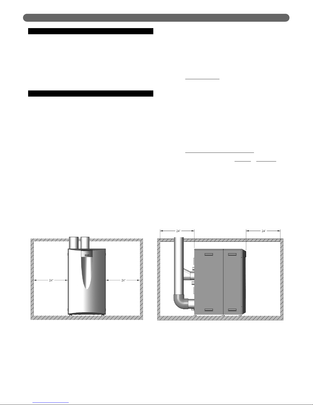
C. ACCESSIBILITY CLEARANCES
1. The PUREFIRE®boiler is certified for closet installations
with zero clearance to combustible construction. In
addition, it is design certified for use on combustible
floors. Do not install on carpeting.
2. Figure 1.1 shows the minimum recommended
clearances to allow reasonable access to the boiler for
inspection and maintenance. However, local codes or
special conditions may require greater clearances.
D. COMBUSTION AND VENTILATION AIR
1. The PUREFIRE®boiler is designed for operation with
combustion air piped directly to the boiler from
outside the building (sealed combustion). Combustion
air can be supplied from within the building only if
adequate combustion and ventilation air is provided
in accordance with the section of the National Fuel
Gas Code entitled, “Air for Combustion and
Ventilation” or applicable provisions of the local
building codes.
2. If the combustion air is piped directly to the boiler
from outside the building, no additional combustion
or ventilation air is required. Otherwise, follow the
National Fuel Gas Code recommendations
summarized in subsections 3 through 10.
3. Required Combustion Air Volume: The total required
volume of indoor air is to be the sum of the required
volumes for all appliances located within the space.
Rooms communicating directly with the space in
which the appliances are installed and through
combustion air openings sized as indicated in
Subsection 3 are considered part of the required
volume. The required volume of indoor air is to be
determined by one of two methods.
a. Standard Method
: The minimum required volume
of indoor air (room volume) shall be 50 cubic feet
per 1000 BTU/Hr (4.8 m3/kW). This method is to
be used if the air infiltration rate is unknown or if
the rate of air infiltration is known to be greater
than 0.6 air changes per hour. As an option, this
method may be used if the air infiltration rate is
known to be between 0.6 and 0.4 air changes per
hour. If the air infiltration rate is known to be
below 0.4 then the Known Air Infiltration Rate
Method must be used. If the building in which this
appliance is to be installed is unusually tight, PB
Heat recommends that the air infiltration rate be
determined.
b. Known Air Infiltration Rate Method
:
where:
I
fan
= Input of the fan assisted appliances
in Btu/hr
ACH = air change per hour (percent of the
volume of the space exchanged per
hour, expressed as a decimal)
Note: These calculations are not to be used for
infiltration rates greater than 0.60 ACH.
3
PREINSTALLATION
Figure 1.1: Minimum Accessibility Clearances – PF-850, PF-1000
15 ft
3
I
fan
ACH 1000
Btu
/
hr
Required Volume
fan
=
⎛
⎜
⎝
⎛
⎜
⎝
Page 6
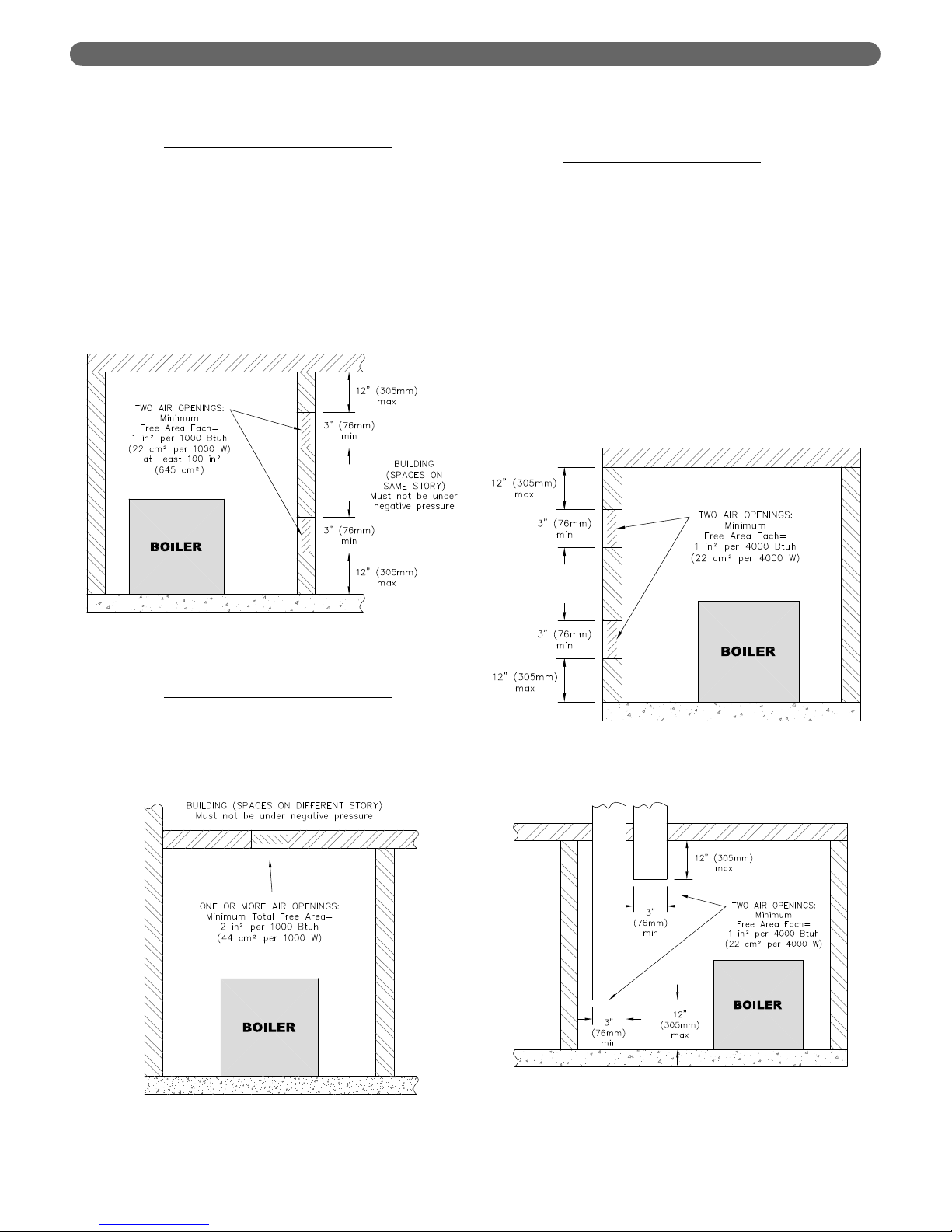
4. Indoor Air Opening Size and Location: Openings
connecting indoor spaces shall be sized and located as
follows:
a. Combining Spaces on the Same Floor
: Provide
two permanent openings communicating with
additional spaces that have a minimum free area
of 1 in
2
per 1000 Btu/hr (22 cm2per 1000 W) of
the total input rating of all gas fired equipment but
not less than 100 in
2
(645 cm2). One opening is
to begin within 12 inches (305 mm) from the top
of the space and the other is to begin within 12
inches (305 mm) from the floor. The minimum
dimension of either of these openings shall be 3
inches (76 mm). See Figure 1.2 for an illustration
of this arrangement.
b. Combining Spaces on Different Floors
: Provide
one or more permanent openings communicating
with additional spaces that have a total minimum
free area of 2 in
2
per 1000 Btu/hr (44 cm2per
1000 W) of total input rating of all equipment. See
Figure 1.3 for an illustration of this arrangement.
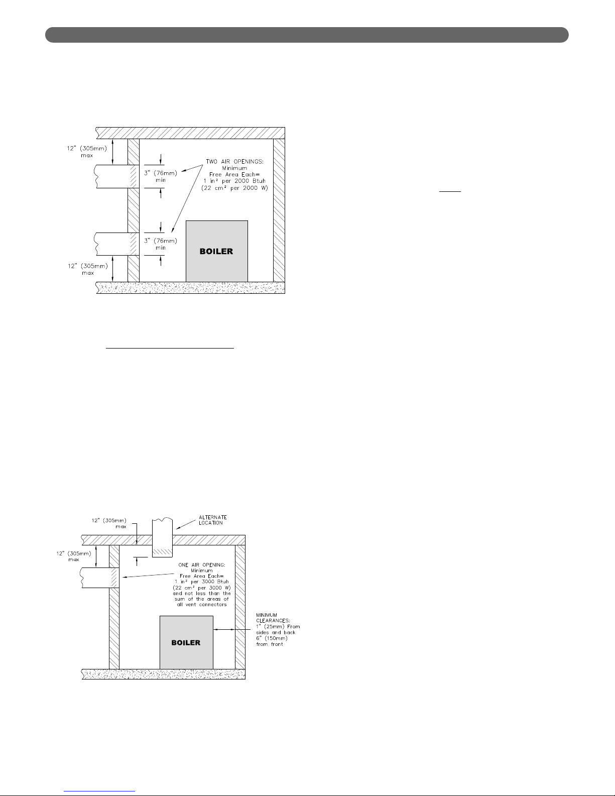
5. Outdoor Combustion Air: Outdoor combustion air is
to be provided through one or two permanent
openings. The minimum dimension of these air
openings is 3 inches (76 mm).
a. Two Permanent Opening Method
: Provide two
permanent openings. One opening is to begin
within 12 inches (305 mm) of the top of the
space and the other is to begin within 12 inches
(305 mm) of the floor. The openings are to
communicate directly or by ducts with the
outdoors or with spaces that freely communicate
with the outdoors. The size of the openings shall
be determined as follows:
i. Where communicating directly or through
vertical ducts with the outdoors each opening
shall have a minimum free area of 1 in
2
per
4000 Btu/hr (22 cm
2
per 4000 W) of total input
rating for all equipment in the space. See Figure
1.4 for openings directly communicating with
the outdoors or Figure 1.5 for openings
connected by ducts to the outdoors.
4
Figure 1.4: Air Openings – All Air Directly from
Outdoors
Figure 1.5: Air Openings – All Air from Outdoors
through Vertical Ducts
PREINSTALLATION
Figure 1.2: Air Openings – All Air from Indoors
on the Same Floor
Figure 1.3: Air Openings – All Air from Indoors
on Different Floors
Page 7
ii. Where communicating with the outdoors
through horizontal ducts, each opening shall
have a minimum free area of 1 in
2
per 2000
Btu/hr (22 cm2per 2000 W) of total rated
input for all appliances in the space. See
Figure 1.6.
b. One Permanent Opening Method
: Provide one
permanent opening beginning within 12 inches
(305 mm) of the top of the space. The opening
shall communicate directly with the outdoors,
communicate through a vertical or horizontal duct,
or communicate with a space that freely
communicates with the outdoors. The opening
shall have a minimum free area of 1 in
2
per 3000
Btu/hr of total rated input for all appliances in the
space and not less than the sum of the crosssectional areas of all vent connectors in the space.
The gas-fired equipment shall have clearances of
at least 1 inch (25 mm) from the sides and back
and 6 inches (150 mm) from the front of the
appliance. See Figure 1.7 for this arrangement.
6. Combination Indoor and Outdoor Combustion Air: If
the required volume of indoor air exceeds the
available indoor air volume, outdoor air openings or
ducts may be used to supplement the available indoor
air provided:
a. The size and location of the indoor openings
comply with Subsection 3.
b. The outdoor openings are to be located in
accordance with Subsection 4.
c. The size of the outdoor openings are to be sized
as follows:
where:
A
req
= minimum area of outdoor openings.
A
full
= full size of outdoor openings calculated
in accordance with Subsection 4.
V
avail
= available indoor air volume
V
req
= required indoor air volume
7. Engineered Installations: Engineered combustion air
installations shall provide an adequate supply of
combustion, ventilation, and dilution air and shall be
approved by the authority having jurisdiction.
8. Mechanical Combustion Air Supply:
a. In installations where all combustion air is
provided by a mechanical air supply system, the
combustion air shall be supplied from the
outdoors at the minimum rate of 0.35 ft
3
/min per
1000 Btu/hr (0.034 m
3
/min per 1000 W) of the
total rated input of all appliances in the space.
b. In installations where exhaust fans are installed,
additional air shall be provided to replace the
exhaust air.
c. Each of the appliances served shall be interlocked
to the mechanical air supply to prevent main
burner operation when the mechanical air supply
system is not in operation.
d. In buildings where the combustion air is provided
by the mechanical ventilation system, the system
shall provide the specified combustion air rate in
addition to the required ventilation air.
9. Louvers & Grills:
a. The required size of openings for combustion,
ventilation, and dilution air shall be based on the
net free area of each opening.
i. Where the free area through a louver or grille
is known, it shall be used in calculating the
opening size required to provide the free area
specified.
ii. Where the free area through a louver or grille
is not known, it shall be assumed that wooden
louvers will have 25% free area and metal
louvers and grilles will have 75% free area.
iii. Non-motorized dampers shall be fixed in the
open position.
b. Motorized dampers shall be interlocked with the
equipment so that they are proven in the full open
position prior to ignition and during operation of
the main burner.
5
Figure 1.6: Air Openings – All Air from Outdoors
through Horizontal Ducts
Figure 1.7: Air Openings – All Air from Outdoors
through One Opening
PREINSTALLATION
A
req
= A
full
x 1 –
V
avail
V
req
⎛
⎜
⎝
⎛
⎜
⎝
Page 8
i. The interlock shall prevent the main burner
from igniting if the damper fails to open during
burner startup.
ii. The interlock shall shut down the burner if the
damper closes during burner operation.
10. Combustion Air Ducts:
a. Ducts shall be constructed of galvanized steel or
an equivalent corrosion- resistant material.
b. Ducts shall terminate in an unobstructed space,
allowing free movement of combustion air to the
appliances.
c. Ducts shall serve a single space.
d. Ducts shall not serve both upper and lower
combustion air openings where both such
openings are used. The separation between ducts
serving upper and lower combustion air openings
shall be maintained to the source of combustion
air.
e. Ducts shall not be screened where terminating in
an attic space.
f. Horizontal upper combustion air ducts shall not
slope downward toward the source of the
combustion air.
g. Combustion air intake openings located on the
exterior of buildings shall have the lowest side of
the combustion air intake opening at least 12
inches (305 mm) above grade.
11. Refer to Section 3 of this manual, Venting & Air Inlet
Piping, for specific instructions for piping the exhaust
and combustion air.
E. PLANNING THE LAYOUT
1. Prepare sketches and notes showing the layout of the
boiler installation to minimize the possibility of
interferences with new or existing equipment, piping,
venting and wiring.
2. The following sections of this manual should be
reviewed for consideration of limitations with
respect to:
a. Venting and Air Inlet Piping: Section 3
b. Water Piping: Section 4
c. Fuel Piping: Section 5
d. Condensate Removal: Section 6
e. Electrical Connections: Section 7
f. Boiler Control: Section 8
g. Boiler Dimensions and Ratings: Section 12
6
PREINSTALLATION
Do not install this boiler where gasoline or other
flammable liquids or vapors are stored or are in use.
WARNING
This boiler is certified as an indoor appliance. Do not
install this boiler outdoors or locate where it will be
exposed to freezing temperatures.
WARNING
Do not install this boiler in the attic.
WARNING
Page 9
7
BOILER SET-UP
A. GENERAL
1. PUREFIRE®boilers are intended for installation in an
area with a floor drain or in a suitable drain pan. Do
not install any boiler where leaks or relief valve
discharge will cause property damage.
2. The P
UREFIRE
®
boiler is not intended to support
external piping. All venting and other piping should
be supported independently of the boiler.
3. Many jacket panels on the P
UREFIRE
®
boiler are
removable to allow inspection and maintenance. Do
not attached fixed brackets for piping or wiring on
removable jacket parts. Piping and/or wiring should
not obstruct access to removable panels.
4. Install the boiler level to prevent condensate from
backing up inside the boiler.
5. Use leveling feet to assure that the boiler is completely
level. This will prevent condensate from collecting in
the boiler and causing degradation of the heat
exchanger.
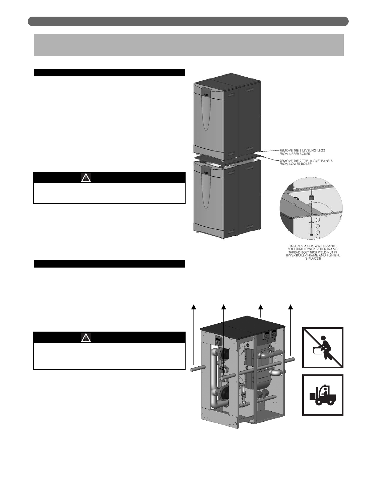
B. STACKING MULTIPLE BOILERS
Identical PF-850 and PF-1000 boilers can be stacked to
save floor space on the installation. Figure 2.1 shows how
the upper boiler is to be attached to the lower boiler.
1. Remove all side jacket panels from the both boilers
and the top jacket panels from the lower boiler.
2. Remove the leveling legs from the boiler to be
installed on top.
3. Lift the upper boiler into place by passing 5 to 10 foot
(2-3 meter) lengths of 1" to 1-1/4" Schedule 40 or 80
steel pipe through the holes provided in the boiler
frame.
4. Insert spacers, washers and bolts (provided) through
the holes provided in the frame of the lower boiler
and thread them into the threaded inserts on the base
of the upper boiler. Figure 2.1 shows this assembly.
Tighten the bolts securely.
5. Replace all the side jacket panels and discard the top
jacket panels from the lower boiler.
2. BOILER SET-UP
Figure 2.1: Stacking and Securing Boilers
This boiler must be installed level to prevent
condensate from backing up inside the boiler.
CAUTION
Do not lift these boilers by hand. Failure to comply
may result in serious injury, death or major property
damage.
WARNING
Figure 2.2: Lifting the Upper Boiler
DO NOT LIFT
BY HAND
FORKLIFT OR
CRANE LIFT ONLY
Page 10
8
VENTING & AIR INLET PIPING
A. GENERAL
1. Install the PUREFIRE®boiler venting system in accordance
with these instructions and with the National Fuel Gas
Code, ANSI Z223.1/NFPA 54, CAN/CGA B149, and/or
applicable provisions of local building codes.
2. The P
UREFIRE
®
boiler is approved for positive pressure
exhaust venting using either indoor air or air piped
from outside. It is ETL Listed as a Category IV
(Positive Pressure, Condensing Exhaust Vent)
Appliance.
B. APPROVED MATERIALS
1. Table 3.1 lists approved materials for vent pipe (and
adhesives where applicable). Use only these materials
for exhaust vent piping.
2. PVC Pipe and fittings are not to be used for exhaust
venting in confined spaces such as closet or alcove
installations or vent pipe that passes through attics.
3. Table 3.2 lists appropriate materials for air inlet piping.
Air inlet piping is to be sealed suitably to prevent
introduction of dirt, chemicals or other contaminants
to the inlet air stream.
* PVC pipe/fittings are not to be used for venting within
confined spaces.
Notice: Installations in Canada require compliance with
ULC S636 - Standard for Type BH Gas Venting Systems.
C. EXHAUST VENT/AIR INTAKE PIPE
LOCATION
1. Install vent piping before installing water, fuel, or
condensate piping. Working from largest to smallest
diameter reduces the complexity of piping
interferences.
2. Vent and air intake piping is to be installed so that
there is sufficient access for routine inspection as
required in Section 11, of this manual.
3. The vent piping for this boiler is approved for zero
clearance to combustible construction. However, a fire
stop must be used where the vent pipe penetrates
walls or ceilings.
4. The Peerless
®
PUREFIRE®boiler, like all high efficiency,
gas-fired appliances, is likely to produce a vapor
plume due to condensation. Surfaces near the vent
termination will likely become coated with
condensation.
5. The maximum combined vent and air inlet vent
length for the Peerless
®
PUREFIRE®boiler is about 200
equivalent feet (60 m).Be sure that the boiler is
located such that the maximum vent length is not
exceeded.
3. VENTING & AIR INLET PIPING
The venting system for this product is to be installed in
strict accordance with these venting instructions.
Failure to install the vent system properly may result in
severe personal injury, death or major property damage.
WARNING
This vent system operates under positive pressure.
Vent connectors serving appliances vented by
natural draft shall not be connected into any portion
of this venting system. Failure to comply may result
in serious injury, death or major property damage.
WARNING
Only the materials listed below are approved for use
with the
P
UREFIRE
®
boiler. Use only these components
in accordance with these instructions. Failure to use
the correct material may result in serious injury,
death, or major property damage.
WARNING
Table 3.1: Approved Materials for Exhaust Vent Pipe
Use of cellular core pipe for any exhaust vent
component is prohibited. Use of cellular core pipe
may result in severe personal injury, death, or major
property damage.
WARNING
If the maximum equivalent vent length is exceeded,
the maximum burner input rate may be reduced.
NOTICE
Description Material
Conforming to
Standard
Vent Piping
& Fittings
PVC (Sch 40 or 80)*
ANSI/ASTM D1785
CPVC (Sch 40 or 80) ANSI/ASTM D1785
PVC-DWV*
ANSI/ASTM D2665
FasNSeal
®
UL-1738 & ULC-S636
MUGRO
®
ULC-S636
Pipe Cement
(PVC & CPVC Only)
PVC/CPVC Cement ANSI/ASTM D2564
Table 3.2: Approved Materials for Air Inlet Piping
Description Material
Air Inlet Pipe
& Fittings
PVC (Cellular Core or Solid)
CPVC
ABS
Smoke Pipe (Galvanized or Steel)
Dryer Vent Pipe
Flexible Duct
Stainless Steel
Polypropylene
Page 11
VENTING & AIR INLET PIPING
6. Air Intake Pipe Location – Sidewall Venting:
a. Provide 1 foot (30 cm) clearance from the bottom
of the air intake pipe to the level of maximum
snow accumulation. Snow removal may be
necessary to maintain clearances.
b. Do not locate air intake pipe in a parking area
where machinery may damage the pipe.
c. If the vent pipe and air inlet pipe terminations
penetrate the wall at the same level the minimum
distance between them is 8" center-to-center.
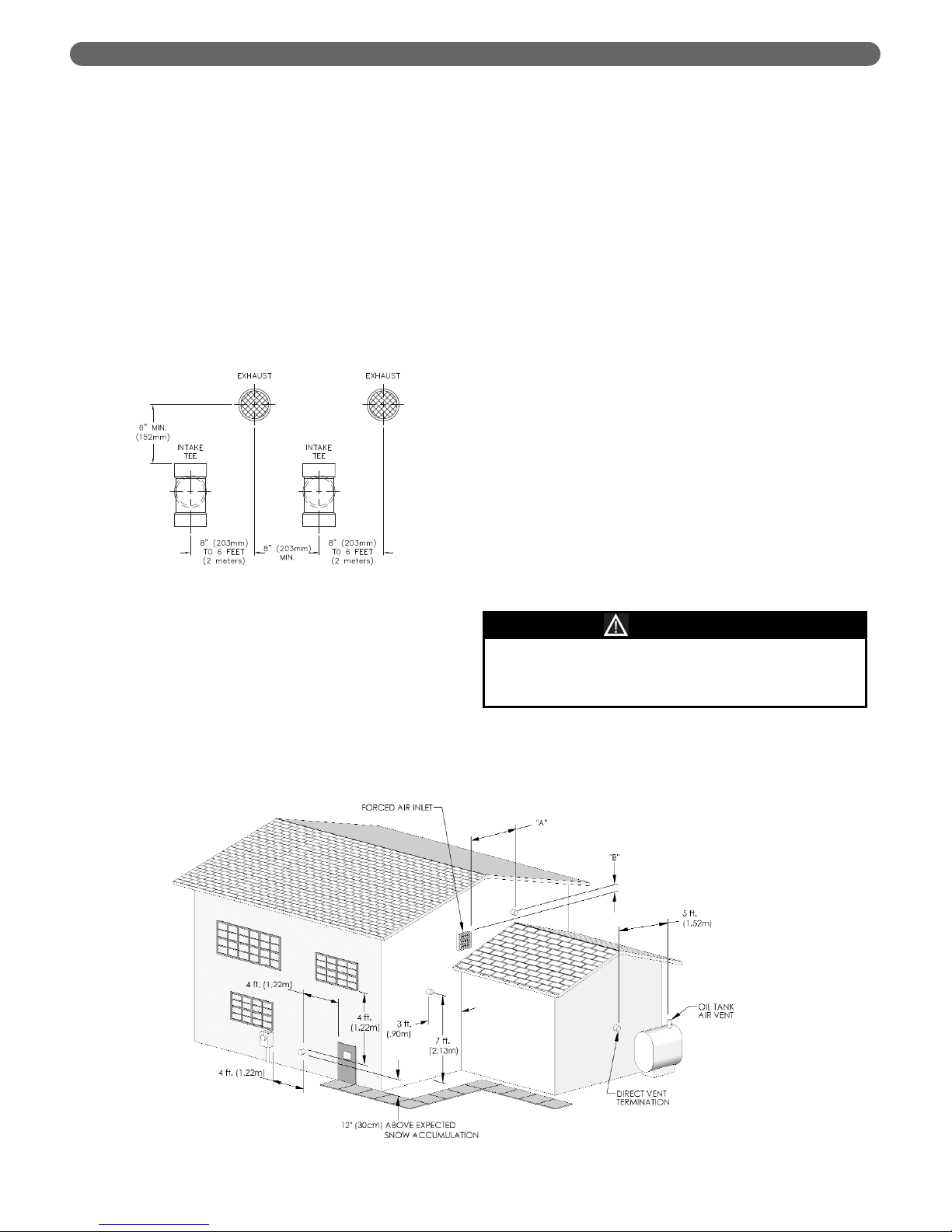
d. For multiple boiler installations, the minimum
horizontal distance between the inlet of one boiler
to the exhaust of an adjacent boiler is 8" center-tocenter. In addition, the minimum vertical distance
between the exhaust and air inlet is 6". See Figure
3.1 for an illustration.
e. The exhaust outlet of the vent pipe should not be
angled any more than 5º from horizontal.
f. Precautions should be taken to prevent
recirculation of flue gases to the air inlet pipe of
the boiler or other adjacent appliances.
7. Sidewall Venting Configuration:
a. See Figure 3.2 for an illustration of clearances for
location of exit terminals of direct-vent venting
systems.
• This boiler vent system shall terminate at least
3 feet (0.9 m) above any forced air inlet
located within 10 ft (3 m). Note: This does not
apply to the combustion air intake of a directvent appliance.
• Provide a minimum of 4 feet (1.22 m)
clearance distance from any door, operable
window, or gravity air intake into any building.
• Provide a minimum of 6 feet (1.83 m)
clearance to adjacent facing walls.
• Provide a minimum of 1 foot (30 cm)
clearance from the bottom of the exit terminal
above the expected snow accumulation level.
Snow removal may be required to maintain
clearance.
• Provide a minimum of 4 feet (1.22 m)
horizontal clearance from electrical meters, gas
meters, gas regulators, and relief equipment. In
no case shall the exit terminal be above or
below the aforementioned equipment unless
the 4 foot horizontal distance is maintained.
• Do not locate the exhaust exit terminal over
public walkways where condensate could drip
and create a hazard or nuisance.
• When adjacent to public walkways, locate the
exit terminal at least 7 feet above grade.
• Do not locate the exhaust termination directly
under roof overhangs to prevent icicles from
forming or recirculation of exhaust gases from
occurring.
• Provide 3 feet clearance from the inside corner
of adjacent walls.
Figure 3.1: Vent Pipe Spacing for Multiple
P
UREFIRE
®
Boilers
Figure 3.2: Exit Terminal Location for Mechanical Draft and Direct-Vent Venting Systems
Condensing flue gases can freeze on exterior
building surfaces which may cause discoloration and
degradation of the surfaces.
CAUTION
9
Page 12
VENTING & AIR INLET PIPING
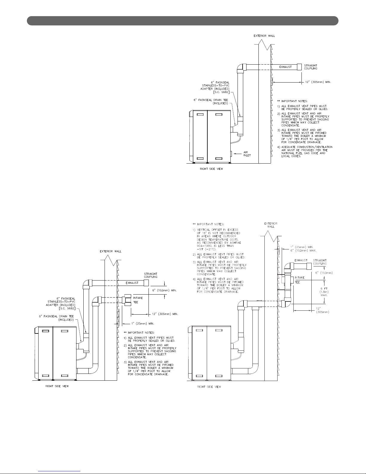
b. Figure 3.3, 3.4 and 3.5 show approved sidewall
venting configurations using standard PVC or
CPVC fittings. A similar configuration using
FasNSeal stainless steel exhaust pipe can be used
with either PVC or other approved material for the
combustion air intake piping.
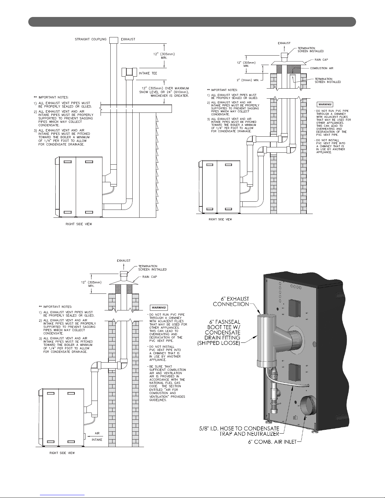
8. Figures 3.6 through 3.8 show recommended vertical
venting configurations.
a. Figure 3.6 illustrates a vertical venting
configuration using PVC inlet and exhaust. A
similar configuration can be constructed using a
FasNSeal stainless steel vent termination. PVC or
other approved materials may be used for air inlet
piping.
i. The opening of the air inlet piping is to be a
minimum of 12" (300 mm) above the
expected snow accumulation on the roof
surface or 24" (600 mm) above the roof
surface, whichever is greater.
ii. Locate the opening of the exhaust vent pipe a
minimum of 12" above the air inlet opening to
prevent flue gas from recirculating to the air
inlet.
b. Figure 3.7 shows vertical exhaust venting through
an unused chimney. In this case, combustion air is
supplied from inside the building. Section 1.D
provides guidelines for determining adequate
inside air.
c. Figure 3.8 illustrates another vertical venting
configuration through an unused chimney. In this
arrangement the combustion air is supplied
through the chimney as well.
Figure 3.3: Sidewall Exhaust Vent and Air Inlet Pipe
Figure 3.5: Offset Sidewall Exhaust Vent and Air
Inlet Pipe
Figure 3.4: Sidewall Exhaust Vent with Indoor Air
10
Page 13
VENTING & AIR INLET PIPING
Figure 3.6: Vertical Exhaust and Air Inlet Pipe
Figure 3.7: Vertical Exhaust Routed Through an
Unused Chimney with Indoor Air
Figure 3.9: Drain Tee and Air Inlet Connections
Figure 3.8: Vertical Exhaust Routed Through an
Unused Chimney with Outdoor Air
11
Page 14
D. EXHAUST VENT/AIR INTAKE PIPE SIZING
1. PUREFIRE®boiler models PF-850 and PF-1000 are to
be installed using 6" piping for both exhaust and air
inlet. A list of approved materials for the exhaust are
in Table 3.1 and a list of approved materials for air
inlet are in Table 3.2
2. The total combined length of exhaust vent and air
intake piping is 200 equivalent feet (60 m).
a. The P
UREFIRE
®
PF-850 and PF-1000 may be
provided with room air as long as there is
adequate combustion and ventilation air provided.
See Section 1.D: Combustion and Ventilation Air
of this manual for the minimum requirements. In
this case, a maximum of 200 equivalent feet of
exhaust vent pipe can be used.
b. The equivalent length of elbows, tees and other
fittings are listed in Table 3.3.
c. The total equivalent length can be calculated as
shown in Table 3.4.
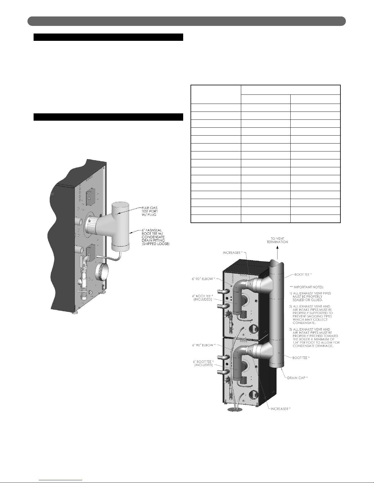
E. EXHAUST VENT/AIR INTAKE
INSTALLATION
1. Figure 3.10 shows the exhaust connection on the rear
of the boiler on the vertical centerline. The exhaust
connection is a 6" FasNSeal stainless steel connection.
2. A 6" FasNSeal stainless steel boot tee with a drain
fitting is included with each PF-850 & PF-1000 boiler.
This should be connected directly to the rear of the
boiler as shown below.
3. The Air Intake connection is a 6" galvanized collar to
the right and below the exhaust connection. This can
be connected to any of the approved air intake piping
materials.
4. The Air Intake connection should be secured with (3)
screws and sealed.
5. Remove all burrs and debris from the joints and fittings.
6. Care should be taken to prevent dirt or debris from
entering the air intake connection. A screen is
provided inside the Air Intake fitting to prevent large
objects from entering the combustion system.
7. Horizontal lengths of exhaust vent must be installed with
a slope of not less than 1/4" per foot (21mm per meter)
toward the boiler to allow condensate to drain from the
vent pipe. If the vent pipe must be piped around an
obstacle that causes a low point in the piping, a drain
with an appropriate trap must be installed.
Les sections horizontales de l’évacuation doivent être
installées avec une pente d’au moins 1/4 po au pied
(21 mm par mètre) en direction de la chaudière afin
que le condensat puisse s’évacuer du tuyau
d’évacuation. Si le tuyau d’évacuation est acheminé
autour d’un obstacle qui crée un point bas dans la
tuyauterie, il est nécessaire alors d’installer un drain
équipé d'une vidange adéquate.
8. All piping must be fully supported. Use pipe hangers
at a minimum of 4 foot (1.22 meter) intervals to
prevent sagging of the pipe.
Tous les tuyaux doivent être parfaitement soutenus.
Utiliser des attaches de tuyau tous les 4 pieds (1,22
mètres) pour éviter le fléchissement des tuyaux.
9. Exhaust and air inlet piping is to be supported
separately and should not apply force to the boiler.
Les tuyaux d’évacuation et d’arrivée d’air doivent
avoir des dispositifs de support distincts et ne pas
exercer de pression sur la chaudière.
10. Penetration openings around the vent pipe and air
intake piping are to be fully sealed to prevent exhaust
gases from entering building structures.
11. PVC & CPVC Piping:
a. Use only solid PVC or CPVC Schedule 40 or 80
pipe for exhaust venting. Cellular core PVC or
CPVC is not approved for exhaust vent.
b. All joints in vent pipe, fittings, attachment to the
boiler stub, and all vent termination joints must be
properly cleaned, primed and cemented. Use only
cement and primer approved for use with PVC or
CPVC pipe that conforms to ANSI/ASTM D2564.
c. A PVC or CPVC coupling can be used as an
outside vent termination. In this configuration,
place one of the 6" diameter screens provided
between the coupling and exhaust connection
before gluing it. This is intended to prevent birds
or rodents from entering.
d. A PVC or CPVC tee can be used as an outside air
intake termination. When using this configuration,
place one of the 6" diameter screens provided
between the tee and the air inlet connection
before gluing it. This is intended to prevent birds
or rodents from entering.
VENTING & AIR INLET PIPING
This appliance uses a positive pressure venting
system. All joints must be sealed completely to
prevent leakage of flue products into living spaces.
Failure to do this may result in severe personal injury,
death or major property damage.
WARNING
Exhaust Air Inlet Total
Straight Length of Pipe 100' 50' 150'
90° Elbows, SR 2 x 5'= 10' 1 x 5' = 5' 15'
45° Elbows, SR 2 x 3' = 6' 6'
Air Intake Tee 0' 0'
Outlet Coupling 0' 0'
Total 171'
Table 3.4: Sample Equivalent Length Calculation
Table 3.3: Equivalent Length of Fittings
Fitting Description Equivalent Length
Elbow, 90° Short Radiusz 5 feet (1.5 m)
Elbow, 90° Long Radius 4 feet (1.2 m)
Elbow, 45° Short Radius 3 feet (0.9 m)
Coupling 0 feet (0 m)
Air Intake Tee 0 feet (0 m)
12
Page 15
F. TEST PORT FOR EXHAUST SAMPLING
1. Figure 3.10 shows an illustration of the plugged
sample port on the outlet of the drain tee for the PF850 and PF-1000 boiler.
2. To obtain an exhaust sample during operation,
remove the test port plug and insert the probe from a
suitable combustion analyzer.
3. Be sure to replace the plug before leaving the boiler
unattended.
G. COMMON VENTING MULTIPLE BOILERS
1. Multiple PUREFIRE®PF-850 and PF-1000 boilers may
be connected to a common vent system if they are set
up to operate in the cascade mode described in
Section 8.
a. The boilers must communicate in a
Master/Dependent relationship provided in the
system software.
b. The backflow prevention valves supplied on the
gas/air premix inlet prevent products of
combustion from backing up through the burners
into occupied space.
c. A safety control algorithm will operate the blower
to prevent backflow in case of a backflow
prevention valve failure.
2. Figure 3.11 shows two P
UREFIRE
®
PF-850 boilers
connected with a common vent system.
a. The drain tee from the common vent section
should be trapped and neutralized separately from
the boilers.
b. The condensate drain from each boiler should be
run separately to the drain system to prevent a
clogged condensate line from shutting down
multiple boilers.
c. Table 3.5 shows recommended sizing for common
vent piping.
VENTING & AIR INLET PIPING
Figure 3.11: Multiple Boilers with Common Venting
Table 3.5: Common Exhaust Vent Sizing
Figure 3.10
Number
of Boilers
Boiler Model
PF-850 PF-1000
2 8" 9"
3 10" 12"
4 12" 12"
5 14" 14"
6 14" 16"
7 16" 16"
8 16" 18"
9 18" 18"
10 18" 20"
11 20" 20"
12 20" 22"
13 20" 22"
14 22" 24"
15 22" 24"
16 24" 24"
13
Page 16

14
VENTING & AIR INLET PIPING
H. BOILER REMOVAL FROM COMMON
VENTING SYSTEM
At the time of removal of an existing boiler, follow these
steps with each appliance remaining connected to the
common venting system placed in operation, while the
other appliances remaining connected to the common
venting system are not in operation:
Retrait de la chaudière d’un système d’évacuation
commun. Au moment de retirer une chaudière existante,
il est important de suivre les étapes suivantes pour chaque
appareil raccordé au système d’évacuation commun qui
sont en service, alors que les autres appareils demeurant
raccordés au système d’évacuation commun ne sont pas
en service :
1. Seal any unused openings in the common venting
system.
Sceller toute ouverture du système d’évacuation
commun non utilisée.
2. Visually inspect the venting system for proper size and
horizontal pitch and determine there is no blockage or
restriction, leakage, corrosion and other deficiencies
which could cause an unsafe condition.
Effectuer un contrôle visuel du système d’évacuation
pour vérifier la taille et la pente horizontale et
s’assurer qu’il n’existe aucun blocage ou obstruction,
fuite, corrosion ni tout autre problème pouvant
menacer la sécurité.
3. Insofar as is practical, close all building doors and
windows and all doors between the space in which
the appliances remaining connected to the common
venting system are located and other spaces of the
building.
Dans la mesure du possible, fermer toutes les portes
et fenêtres de l’immeuble ainsi que toutes les portes
entre l’espace dans lequel les appareils qui demeurent
raccordés au système d’évacuation commun se
trouvent et le reste de l’immeuble.
4. Turn on any clothes dryers and any appliance not
connected to common venting system. Turn on any
exhaust fans, such as range hoods and bathroom
exhausts, so they will operate at maximum speed. Do
not operate a summer exhaust fan.
Mettre en marche les sécheuses et tout autre appareil
non raccordé au système d’évacuation commun.
Mettre en marche tous les ventilateurs aspirant, tels
que les hottes de cuisinière et les ventilateurs de salle
de bain, en les faisant fonctionner à vitesse maximum.
5. Close fireplace dampers.
Ne pas faire fonctionner les ventilateurs aspirant d’été.
Fermer les registres de foyers.
6. Place in operation the appliance being inspected.
Follow the lighting instructions. Adjust thermostat so
appliance will operate continuously.
Mettre en service l’appareil à inspecter. Suivre les
instructions concernant l’allumage. Régler le
thermostat afin que l’appareil fonctionne sans arrêt.
7. Test for spillage at the draft hood relief opening after 5
minutes of main burner operation. Use the flame of a
match or candle, or smoke from a cigarette, cigar, or
pipe.
Vérifier toute fuite à l’orifice de décharge du coupetirage après que le brûleur ait fonctionné pendant 5
minutes. Utiliser la flamme d’une allumette ou d’une
chandelle ou encore la fumée d’une cigarette, d’un
cigare ou d’une pipe.
8. After it has been determined that each appliance
remaining connected to the common venting system
properly vents when tested as outlined above, return
doors, windows, exhaust fans, fireplace dampers and
any other gas-burning appliance to their previous
conditions of use.
Après avoir établi que les résidus de combustion de
chaque appareil qui demeure raccordé au système
commun sont adéquatement évacués lorsque soumis
au test décrit ci-dessus, remettre en place les portes,
fenêtres, portes intérieures, ventilateurs aspirants,
registres de foyer et appareils fonctionnant au gaz.
9. Any improper operation of the common venting system
should be corrected so that the installation conforms
with the National Fuel Gas Code, ANSI Z223.1/NFPA
54 or CAN/CGA B149 Installation Codes.
Tout fonctionnement inadéquat du système
d’évacuation commun doit être corrigé de manière à
respecter les normes du National Fuel Gas Code,
ANSI Z223.1/NFPA 54 et/ou des Codes d’installation
CAN/ACG B149.
10. When resizing any portion of the common venting
system, the common venting system should be resized
to approach minimum size as determined using the
appropriate tables located in the chapter “Sizing of
Category I Venting Systems,” of the National Fuel Gas
Code, ANSI Z223.1/NFPA 54 or CAN/CGA B149
Installation codes.
Lorsqu’il est nécessaire de modifier les dimensions de
toute portion du système d’évacuation commun, ces
dernières doivent être modifiées de manière à
respecter les dimensions minimums indiquées dans les
tableaux du chapitre « Sizing of Category I Venting
Systems » du National Fuel Gas Code, ANSI
Z223.1/NFPA 54 ou des Codes d’installation
CAN/ACG B149.
Page 17
15
A. GENERAL
1. Size water supply and return piping in accordance
with system requirements. Do not use smaller
diameter piping than the boiler connections.
2. If the P
UREFIRE
®
boiler is used to replace an existing
boiler, make sure that the system piping is thoroughly
cleaned and free from debris before installing this boiler.
3. In hydronic systems where sediment may exist, install
a strainer in the boiler return piping to prevent large
particles and pipe scale from entering the boiler heat
exchanger. Use a large mesh screen in the strainer.
4. Install this boiler so that the gas ignition system
components are protected from water (dripping, spraying,
etc.) during operation and service (circulator replacement,
condensate trap cleaning, sensor replacement, etc.).
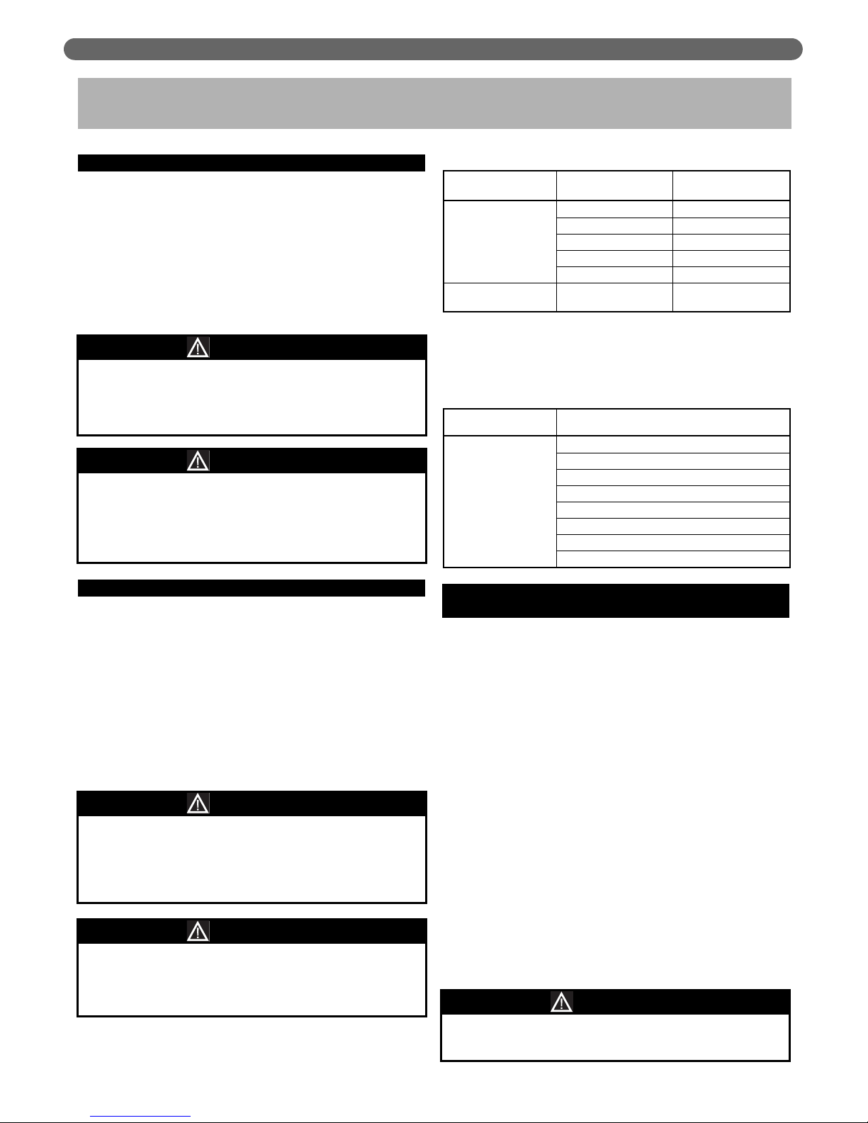
B. OPERATING PARAMETERS
1. The PUREFIRE®boiler is designed to operate in a
closed loop hydronic heating system under forced
circulation. This requires the system to be completely
filled with water and requires a minimum water flow
rate through the boiler to assure proper flow
distribution.
2. The minimum system operating pressure is 14.5 PSI
(69 kPa).
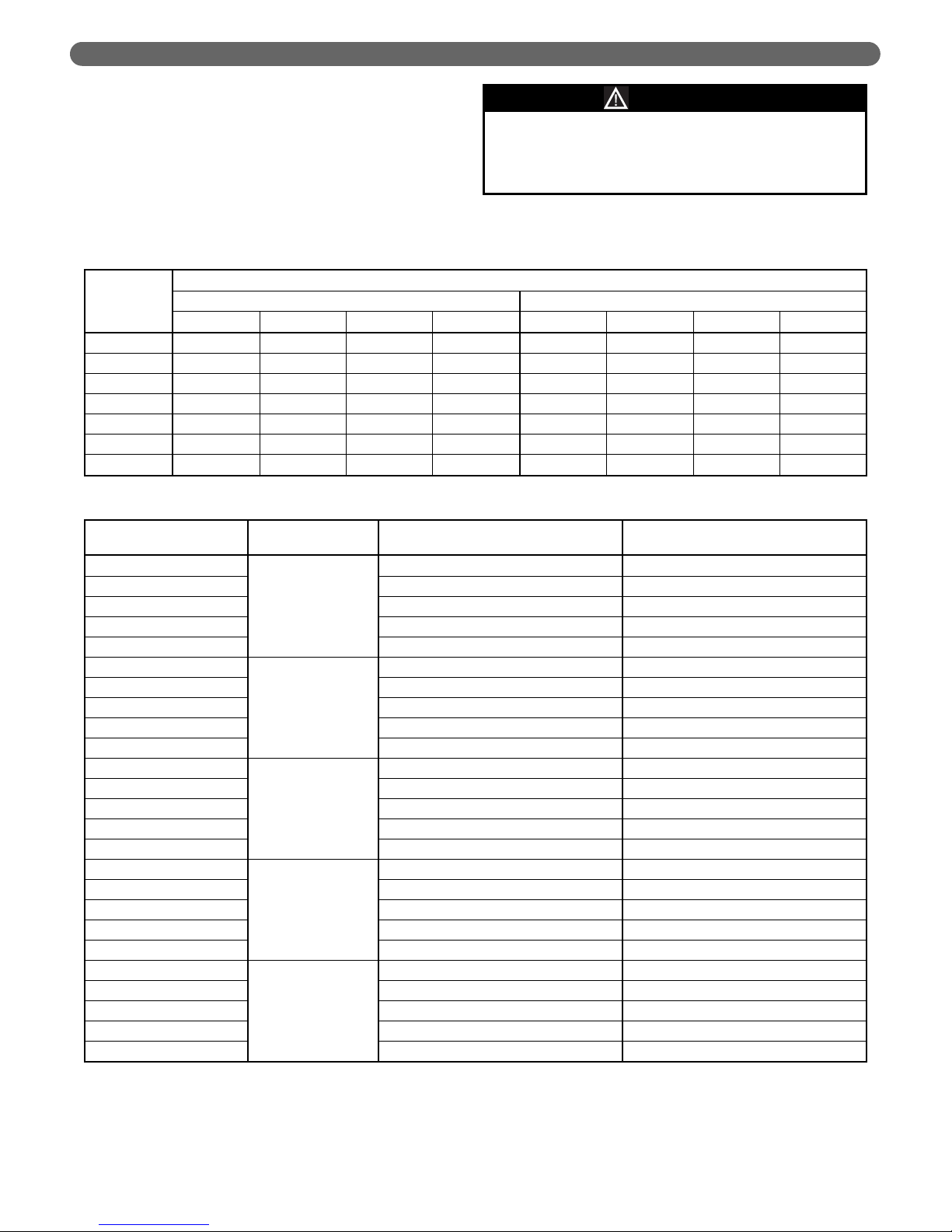
3. Table 4.1 lists the minimum flow rates for each
P
UREFIRE
®
model covered in this manual. Also shown
is the minimum flow rate for 50% glycol solution. For
other glycol concentrations, contact your PB Heat,
LLC representative for the minimum flow rates.
4. Section 4.E provides detailed information about using
glycol for freeze protection. Table 4.2 provides the
water volume of the heat exchangers for calculating
the system volume.
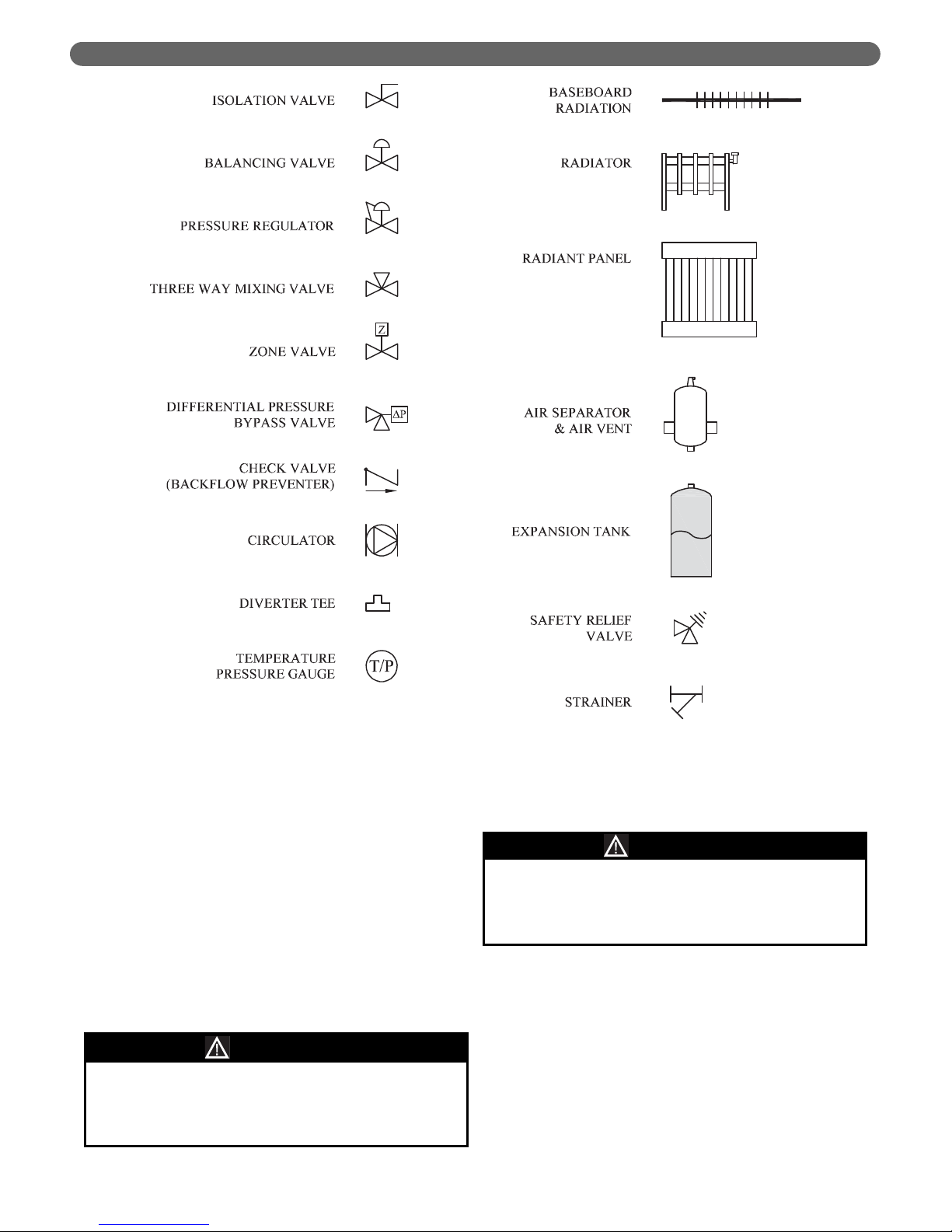
C. SYSTEM COMPONENTS
Figure 4.1 shows the symbol key for piping diagrams in
this section. The following are brief descriptions of system
components.
1. Pressure/Temperature Gauge: A combination
pressure/temperature gauge is provided with each
P
UREFIRE
®
boiler to be mounted in the piping from the
boiler supply to the system as shown in Figure 4.2.
Most local codes require this gauge.
2. Air Elimination: Closed loop hydronic systems require
air elimination devices. As the system water is heated,
dissolved oxygen and other gases will separate from
the liquid. An air elimination device (such as a TACO
Vortech
®
Air Separator) is required to remove the
dissolved gases preventing corrosion in the piping
system and eliminating noise.
3. Expansion Tank: An expansion tank (such as a Bell &
Gossett Series HFT) is required to provide room for
expansion of the heating medium (water or glycol
solution). Consult the expansion tank manufacturer's
instructions for specific information regarding
installation. The expansion tank is to be sized for the
required system volume and capacity. In addition, be
sure that the expansion tank is sized based on the
proper heating medium. Glycol solutions may expand
more than water for a similar temperature rise.
4. Y-Type Strainer or Filter Ball
®
Valve: PB Heat
recommends the use of a strainer device in the system to
prevent dirt or sediment from clogging the heat
exchanger. A 20 mesh stainless steel screen is adequate to
protect the heat exchanger. The strainer should be
cleaned often in the first several months of operation. The
Filter Ball
®
Valve from Jomar International incorporates a
strainer into a ball valve which allows the technician to
isolate the water circuit while cleaning the strainer.
5. Flow Control Valve: Flow control valves such as the
TACO Flo-Chek or Bell & Gossett Flo-Control™ are
used to prevent gravity circulation by incorporating a
check valve with a weighted disc.
4. WATER PIPING & CONTROLS
Use only inhibited propylene glycol solutions which
are specifically formulated for hydronic systems.
Unlike automotive antifreeze, solutions for hydronic
applications contain corrosion inhibitors that will
protect system components from premature failure
due to corrosion.
CAUTION
Use only inhibited propylene glycol solutions which
are specifically formulated for hydronic systems.
Ethylene glycol is toxic and may cause any
environmental hazard if a leak or spill occurs.
WARNING
PUREFIRE
®
Model
Minimum Flow Rate
Water
GPM (LPM)
50% Glycol Solution
GPM (LPM)
PF-850 39.5 (149.5) 49.4 (187.0)
PF-1000 46.5 (176.0) 58.2 (220.3)
Table 4.1: Minimum Boiler Flow Rates
PUREFIRE
®
Model
Total Water Capacity
Gallons Liters
PF-850 6.2 23.4
PF-1000 7.2 27.1
Table 4.2: Heat Exchanger Water Capacity
WATER PIPING & CONTROLS
Page 18
16
6. Pressure Reducing Valve: A pressure reducing valve,
such as the Bell & Gossett B-38 or a TACO #329, is
used in a hydronic system to automatically feed water
to the system whenever pressure in the system drops
below the pressure setting of the valve. These valves
should not be used on glycol systems unless close
supervision of the glycol solution is practiced.
7. Back Flow Preventer: A back flow preventer (check
valve) is required by some jurisdictions to prevent water
in the hydronic system from backing up into the city
water supply. This is especially important on systems in
which glycol solution is used as the heating medium.
8. Pressure Relief Valve: The boiler pressure relief valve is
shipped in the miscellaneous parts box for field
installation. It is extremely important to install this device.
The valve is to be installed on the boiler supply pipe
as shown in Figure 4.2. Pipe the discharge of the relief
valve to within 12” of the floor and close to a floor
drain.
Provide piping that is the same size or larger than the
relief valve outlet.
9. Circulator: The boiler circulator is to be sized to
overcome the pressure drop of the system while
providing the flow required by the boiler.
a. If the boiler is piped in a secondary loop of a
primary/secondary heating system, the circulator
will need only to overcome the resistance of the
boiler and any fittings in that loop.
WATER PIPING & CONTROLS
Figure 4.1: Piping Symbol Key
Do not operate this appliance without installing the
pressure relief valve supplied with the boiler or one
with sufficient relieving capacity in accordance with
the ASME Rating Plate on the boiler heat exchanger.
WARNING
Pipe the discharge of the relief valve as close as
possible to the floor and away from high traffic areas.
Pipe the discharge to a floor drain. Failure to do so
may result in personal injury and/or property damage.
CAUTION
Page 19
17
b. The circulator should be sized based on gross
output of the boiler. Table 4.3 shows the Boiler
Output as reported to the Hydronics Institute
Section of AHRI.
c. The required flow is calculated based on the design
temperature difference from the return to the supply
of the boiler. For a PF-850 with a design temperature
difference of 20°F the calculation is as follows:
Output 816,000
Required Flow =
________=_________
= 81.6 GPM
D
T x 500 20 x 500
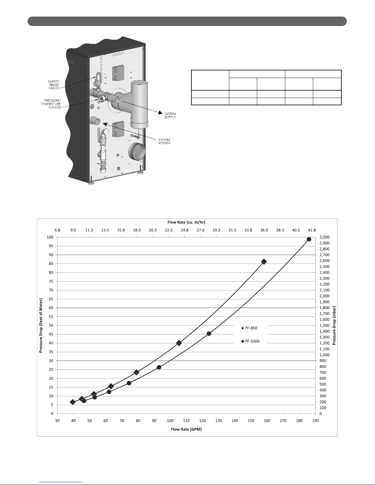
d. The boiler pressure drop for various flow rates
can be determined using Figure 4.3, the P
UREFIRE
®
PF-850/PF-1000 Sizing Graph.
e. Table 4.4 provides the flow rate and pressure drop
information that corresponds to various boiler
temperature rise values (DT). The pressure drop
shown is for the boiler only. If there is significant
system pressure drop in the piping, this should be
considered when specifying circulators.
WATER PIPING & CONTROLS
Table 4.3: Boiler Input and Output
Figure 4.3: PUREFIRE®Circulator Sizing Graph (General Pump – Primary/Secondary)
Figure 4.2: Relief Valve and Pressure/Temperature
Gauge Installation
PUREFIRE
®
Model
Boiler Input Boiler Output
Btu/hr kW Btu/hr kW
PF-850 850,000 249 817,700 240
PF-1000 1,000,000 293 966,000 283
Page 20
18
f. Table 4.5 provides a list of recommended
circulators for boilers on a secondary loop of a
primary secondary system which uses water as a
heating medium.
g. Special consideration must be given if a glycol
based anti-freeze solution is used as a heating
medium. Propylene glycol has a higher viscosity
than water, therefore the system pressure drop will
be higher.
Table 4.4: Flow Rate & Pressure Drop for Various System Temperature Rise Values
DT
(°F)
Flow Rate & Pressure Drop
PF-850 PF-1000
GPM FT cu. m/hr mbar GPM FT cu. m/hr mbar
10 163.5 91.90 37.14 2747 193.2 98.87 43.88 2955
15 109.0 42.65 24.76 1275 128.8 45.37 29.25 1356
20 81.8 24.94 18.57 745 96.6 26.30 21.94 786
25 65.4 16.52 14.86 494 77.28 17.32 17.55 518
30 54.5 11.83 12.38 353 64.4 12.35 14.63 369
35 46.7 8.93 10.61 267 55.2 9.29 12.54 278
40 39.5 6.57 8.97 196 48.3 7.29 10.97 218
Table 4.5: Circulator Selection Chart (General Pump – Primary/Secondary Piping)
Circulator
Manufacturer
DT
(°F) PF-850 PF-1000
Taco
20
1635/1935, 138, 133 1635/1935
Grundfos UPS50-160/2F speed 2 UPS50-160/2F, speed 3
Bell & Gossett PD-38 PD-38
Wilo - Top S (1 Ph) 2.0 x 50 (max) 2.0 x 50 (max)
Wilo - Stratos 2.0 3 x 35 3.0 3 x 30
Taco
25
1635/1935, 132 1635/1935, 132
Grundfos UPS40-80/4F speed 3 UPS50-80/4F, speed 3
Bell & Gossett PL-130 PL-130
Wilo - Top S (1 Ph) 1.5 x 30 (max) 1.5 x 30 (min)
Wilo - Stratos 1.5 3 x 40 1.5 3 x 40
Taco
30
1611/1911, 131, 122, 121 1635/1935, 131
Grundfos UPS50-60F, speed 3 UPS40-80/4F, speed 3
Bell & Gossett 2.5" / LD3 2.5" / LD3
Wilo - Top S (1 Ph) 1.5 x 30 (min) 1.5 x 30 (min)
Wilo - Stratos 1.5 3 x 40 1.5 3 x 40
Taco
35
122, 121 122
Grundfos UPS50-60F, speed 2 UPS50-60F, speed 3
Bell & Gossett PL-75 2.5" / LD3
Wilo - Top S (1 Ph) 1.5 x 20 (max) 1.5 x 20 (max)
Wilo - Stratos 1.25 3 x 30 1.25 3 x 30
Taco
40
120 2400-60/2400-65
Grundfos UPS43-44FC, speed 3 UPS50-60F, speed 2
Bell & Gossett PL-45/NRF-45 PL-45
Wilo - Top S (1 Ph) 1.5 x 20 (min) 1.5 x 20 (min)
Wilo - Stratos 1.25 3 x 30 1.25 3 x 30
WATER PIPING & CONTROLS
The circulator sizing given is for primary/secondary
installations only. The system circulators must be
sized based on the flow and pressure drop
requirements of the system.
NOTICE
Page 21

D. SYSTEM PIPING
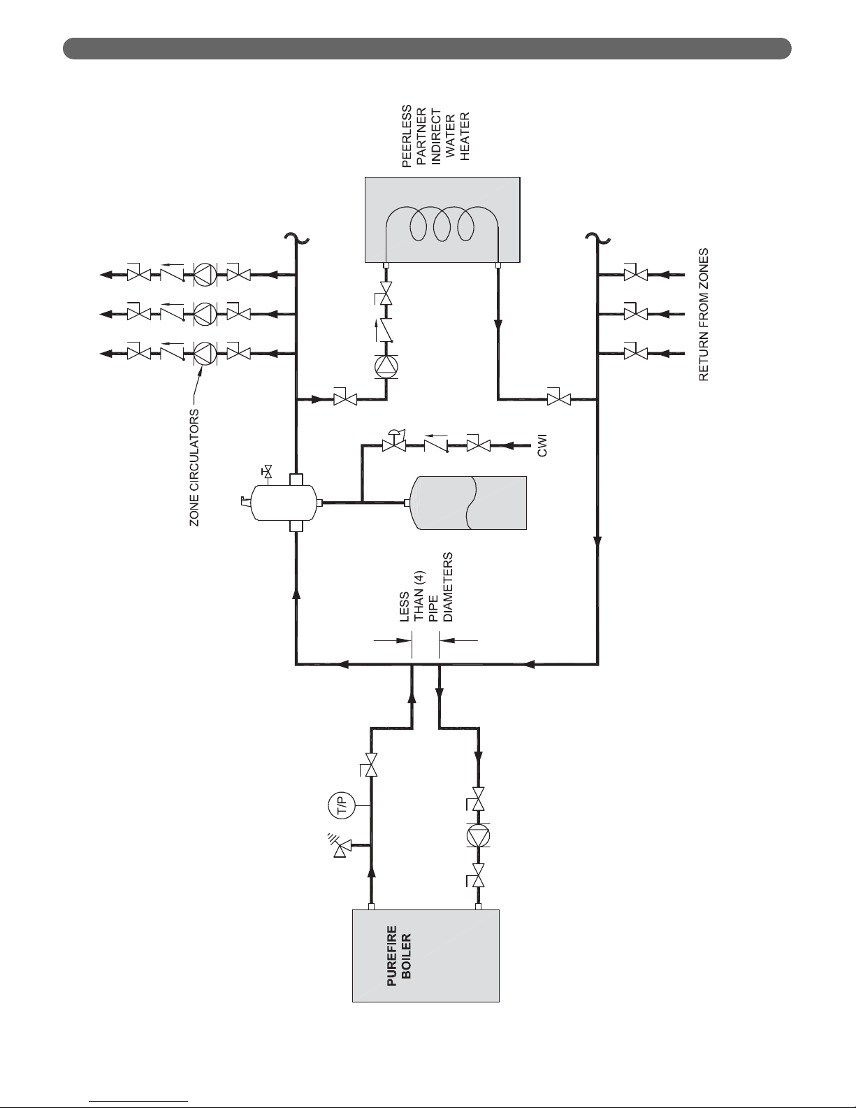
1. Figure 4.4 shows a single boiler with multiple heating
zones. In this case, the DHW zone is piped in parallel
to the heating zones on the primary loop.
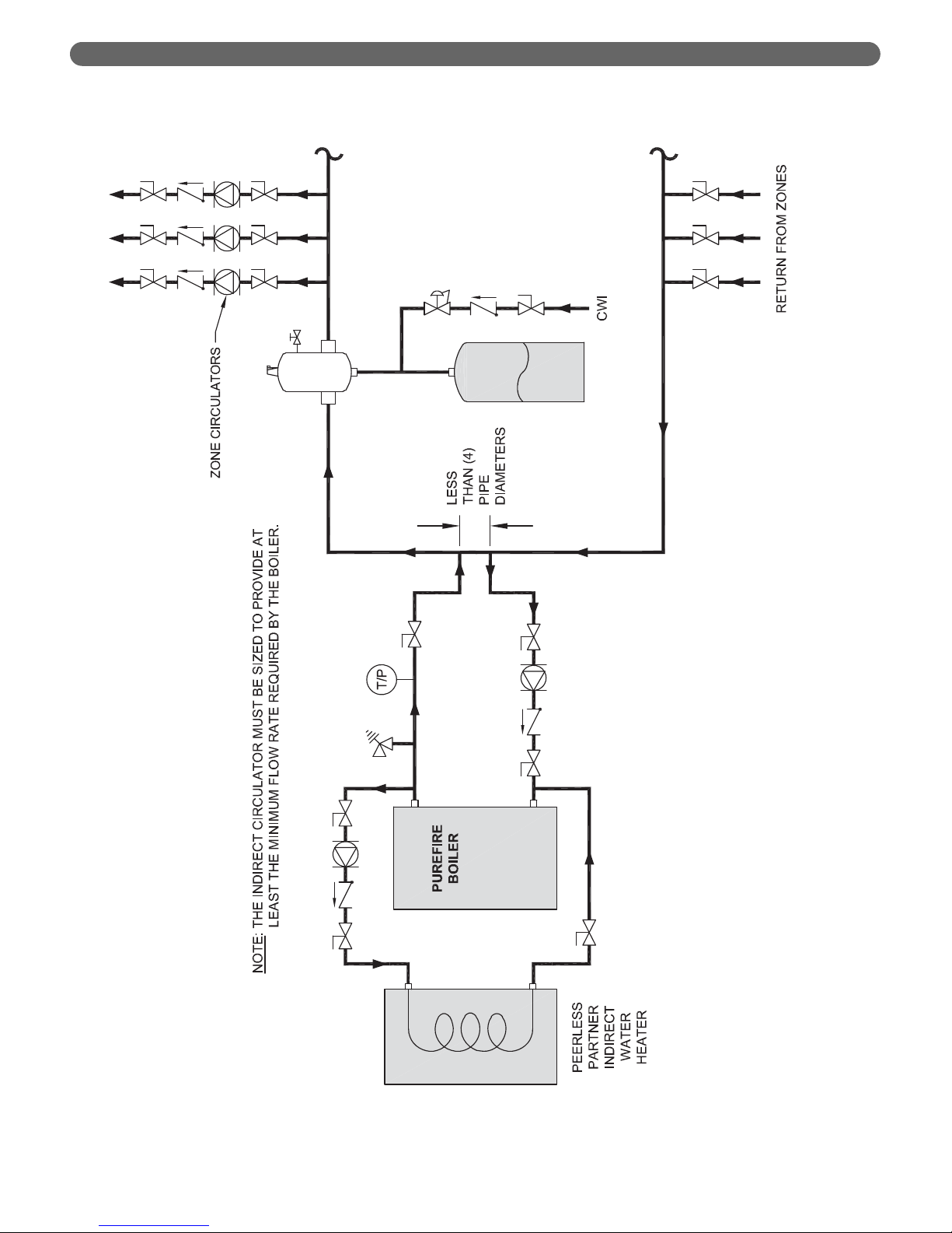
2. An alternate piping schematic for piping an indirect
water heater, such as the Peerless
®
Partner®, is
depicted in Figure 4.5. Note that, in this configuration,
the circulating pump for the indirect tank must be
sized to provide the minimum flow rate of the boiler.
In this configuration, both the GEN and CH
circulation pumps should be wired to the CH Pump
output on the terminal strip. This is required to
prevent the General (Boiler) pump from running when
a DHW demand is being satisfied. The total load of
CH and GEN pumps must not exceed 10 amps. If the
load is higher, then an isolation relay must be used.
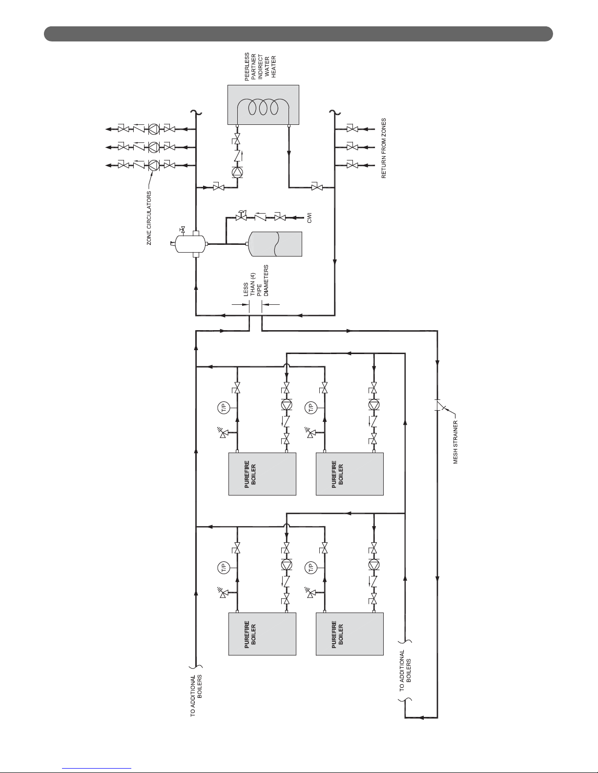
3. The configuration illustrated in Figure 4.6 is for
multiple boilers. This figure shows an indirect DHW
tank in parallel with the heating zones. Notice that the
return to the boilers from the closely spaced tees in
the primary secondary arrangement is reverse return
to provide similar lengths of piping through each
boiler. This configuration shows the boilers in groups
of two to take advantage of the P
UREFIRE
®
PF-850 or
PF-1000 stacking capability.
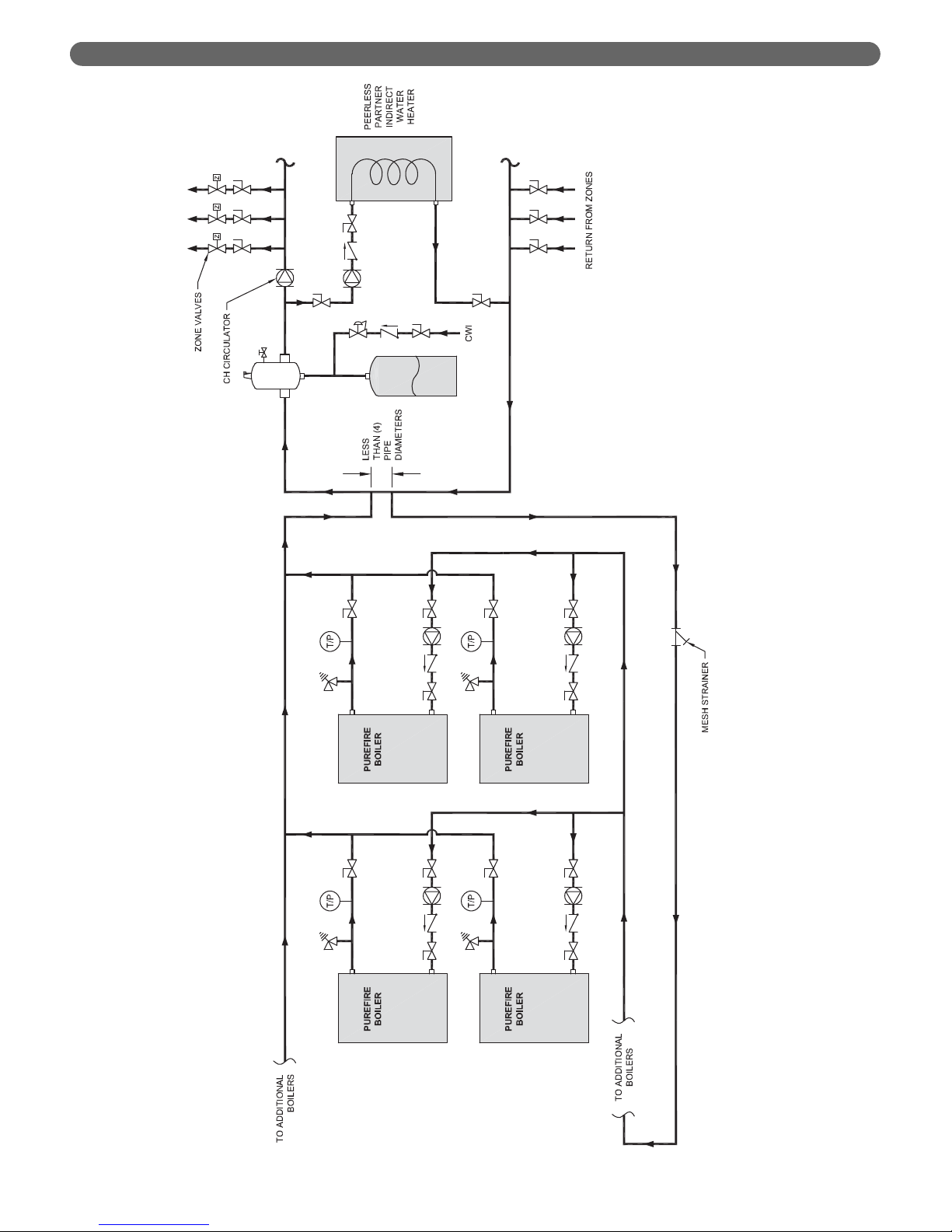
4. Figure 4.7 shows a multiple boiler configuration which
uses zone valves instead of zone circulators. Systems
which combine both zone valves and zone circulators
can help to minimize electrical loads if there are small
zones in the system. Contact your PB Heat, LLC
representative for assistance with larger systems.
E. FREEZE PROTECTION
1. Glycol for hydronic applications is specially formulated
for heating systems. It includes inhibitors which prevent
the glycol from attacking metallic system components.
Make sure that the system fluid is checked for correct
glycol concentration and inhibitor level.
2. Use only inhibited polypropylene glycol solutions of
up to 50% by volume. Ethylene glycol is toxic and
can chemically attack gaskets and seals used in
hydronic system.
3. The anti-freeze solution should be tested at least once
per year and as recommended by the manufacturer of
the product.
4. Anti-freeze solutions expand more than water. For
example, a 50% by volume solution expands 4.8%
with a 148°F temperature rise while water expands
about 3% for the same temperature increase.
Allowance for this expansion must be considered in
sizing expansion tanks and related components. Table
4.2 provides the water capacity of the heat exchanger
to help in system volume calculations.
5. The flow rate in systems utilizing glycol solutions
should be higher than in a water system to
compensate for decreased heating capacity of the fluid.
6. Due to increased flow rate and fluid viscosity, the
circulator head requirement will increase. Contact the
pump manufacturer to correctly size the circulator for
a particular application based on the glycol
concentration and heating requirements.
7. A strainer, sediment trap, or some other means for
cleaning the piping system must be provided. It
should be located in the return line upstream of the
boiler and must be cleaned frequently during the
initial operation of the system. Glycol is likely to
remove mill scale from new pipe in new installations.
8. Glycol solution is expensive and leaks should be
avoided. Weld or solder joints should be used where
possible and threaded joints should be avoided.
Make-up water should not be added to the system
automatically when glycol solution is used. Adding
make-up water will dilute the system and reduce the
ability of the solution to protect from freezing.
9. Check local regulations to see if systems containing
glycol solutions must include a back-flow preventer or
require that the glycol system be isolated from the
water supply.
10. Do not use galvanized pipe in glycol systems.
11. Use water that is low in mineral content and make
sure that there are no petroleum products in the
solution.
a. Less than 50 ppm of calcium
b. Less than 50 ppm of magnesium
c. Less than 100 ppm (5 grains/gallon) of total
hardness
d. Less than 25 ppm of chloride
e. Less than 25 ppm of sulfate
12. Check with the local water supplier for chemical
properties of the water.
13. The following test will determine if the water is of the
appropriate hardness. Collect a sample of 50% water
to 50% propylene glycol. Let the solution stand for 812 hours shaking it occasionally. If white sediment
forms, the water is too hard and should not be used
to dilute the glycol.
14. Mix the solution at room temperature.
15. Do not use a chromate treatment.
16. Refer to Technical Topics #2a published by the
Hydronics Institute for further glycol system
considerations.
WATER PIPING & CONTROLS
19
Page 22
20
WATER PIPING & CONTROLS
Figure 4.4: Recommended Piping – One Boiler with Multiple CH Zones & One DHW Tank
Page 23
21
WATER PIPING & CONTROLS
Figure 4.5: Alternate Piping – One Boiler with Multiple CH Zones & One DHW Tank
Page 24
22
WATER PIPING & CONTROLS
Figure 4.6: Recommended Piping – Multiple Boilers with Multiple CH Zones & One DHW Tank
Page 25
23
WATER PIPING & CONTROLS
Figure 4.7: Alternate Piping – Multiple Boilers with Multiple CH Zones (Zone Valves) & One DHW Tank
Page 26
24
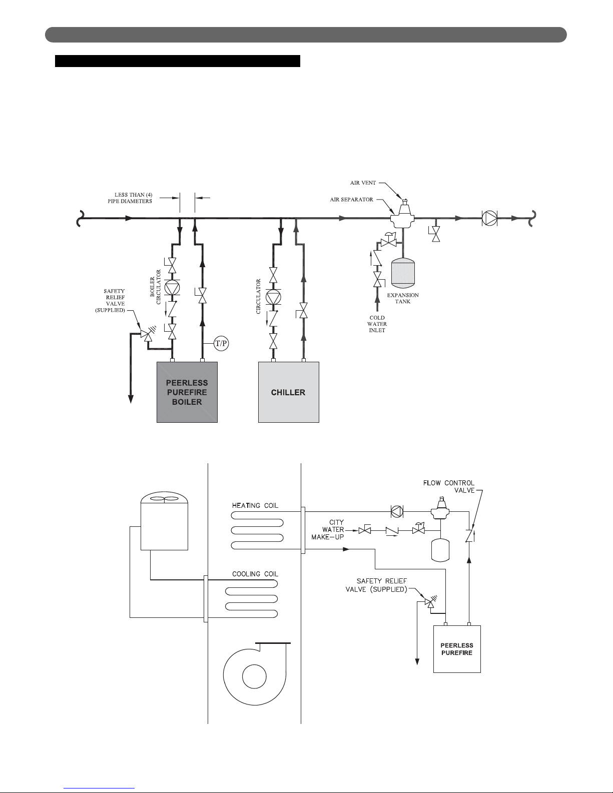
F. SPECIAL APPLICATIONS
1. If the PUREFIRE®boiler is used in conjunction with a
chilled medium system, pipe the chiller in a separate
secondary loop.
a. Assure that the boiler circulator is disabled during
chiller operation so that chilled water does not
enter the boiler.
b. Install a flow control valve (spring check valve) to
prevent gravity flow through the boiler.
c. See Figure 4.8 for recommended system piping for
chiller operation.
2. For boilers connected to heating coils in a forced air
system where they may be exposed to chilled air
circulation, install flow control valves or other
automatic means to prevent gravity circulation of the
boiler water during cooling cycles. See Figure 4.9 for
an illustration.
WATER PIPING & CONTROLS
Figure 4.8: Boiler in conjunction with a Chilled Water System
Figure 4.9: Boiler Connected to a Heating Coil in a Forced Air System
Page 27

25
A. GENERAL
1. All fuel piping to the PUREFIRE®boiler is to be in
accordance with local codes. In the absence of local
regulations refer to the National Fuel Gas Code, ANSI
Z223.1/NFPA 54.
2. Size and install fuel piping to provide a supply of gas
sufficient to meet the maximum demand of all
appliances supplied by the piping.
B. FUEL LINE SIZING
1. The required flow rate of fuel gas to the boiler can be
determined by the following:
2. As an alternative, use Table 5.1 to determine the
required gas flow rate. This table uses typical heating
values for natural gas and liquefied petroleum (LP) gas.
3. Table 5.2 shows the maximum flow capacity of
several pipe sizes based on 0.3" w.c. pressure drop.
The values shown are based on a natural gas specific
gravity of 0.60.
4. Table 5.3 shows the maximum capacity of pipe sizes
for LP gas with a specific gravity of 1.50.
5. Size the fuel gas supply piping for no more than 0.5
in. w.c. pressure drop between the gas pressure
regulator and the boiler.
C. GAS SUPPLY PIPING - INSTALLATION
1. Do not install any piping directly in front of the boiler
or along either side. Always provide clearance for
removal of the front cover or side panels for
inspection and maintenance.
Boiler Input Rate
Gas Heating Value
Input Rate
(
ft
³
/
hr
)
=
(
Btu
/
hr
)
(
Btu
/
ft
³
)
FUEL PIPING
5. FUEL PIPING
PUREFIRE
®
Model
Required Input Rate
Natural Gas
(@1000 Btu/cu.ft)
LP Gas
(@ 2,500 Btu/cu.ft)
ft3/hr m3/hr ft3/hr m3/hr
PF-850 850 24.1 340 9.6
PF-1000 1000 28.3 400 11.3
Table 5.1: Required Fuel Input
Pipe
Length
1-1/4"
Pipe
1-1/2"
Pipe
2" Pipe
2-1/2"
Pipe
3" Pipe 4" Pipe 6" Pipe
ft (m)
10
(3.0)
1,050
(30)
1,600
(45)
3,050
(86)
4,800
(136)
8,500
(241)
17,500
(496)
44,000
(1246)
20
(6.1)
730
(21)
1,100
(31)
2,100
(59)
3,300
(93)
5,900
(167)
12,000
(340)
31,000
(878)
30
(9.1)
590
(17)
890
(25)
1,650
(47)
2,700
(76)
4,700
(133)
9,700
(275)
25,000
(708)
40
(12.2)
500
(14)
760
(22)
1,450
(41)
2,300
(65)
4,100
(116)
8,300
(235)
22,000
(623)
50
(15.2)
440
(12)
670
(19)
1,270
(36)
2,000
(57)
3,600
(102)
7,400
(210)
20,000
(566)
60
(18.3)
400
(11)
610
(17)
1,150
(33)
1,850
(52)
3,250
(92)
6,800
(193)
18,000
(510)
70
(21.3)
370
(10)
560
(16)
1,050
(30)
1,700
(48)
3,000
(85)
6,200
(176)
17,000
(481)
80
(24.4)
350
(10)
530
(15)
930
(26)
1,500
(42)
2,600
(74)
5,400
(153)
15,000
(425)
90
(27.4)
320
(9)
490
(14)
870
(25)
1,400
(40)
2,500
(71)
5,100
(144)
14,000
(396)
100
(30.5)
305
(9)
460
(13)
710
(20)
1,130
(32)
2,000
(57)
4,100
(116)
11,500
(326)
Table 5.2: Pipe Capacity – Natural Gas
Maximum Capacity of pipe in cubic feet per hour (cubic meters
per hour) with a pressure drop of 0.3" of water (75 Pa).
Pipe
Length
1-1/4"
Pipe
1-1/2"
Pipe
2" Pipe
2-1/2"
Pipe
3" Pipe 4" Pipe 6" Pipe
ft (m)
10
(3.0)
662
(18.7)
1,008
(28.5)
1,922
(54.4)
3,024
(85.6)
5,355
(151.6)
11,025
(312.2)
27,720
(784.9)
20
(6.1)
460
(13.0)
693
(19.6)
1,323
(37.5)
2,079
(58.9)
3,717
(105.3)
7,560
(214.1)
19,530
(553.0)
30
(9.1)
372
(10.5)
561
(15.9)
1,040
(29.4)
1,701
(48.2)
2,961
(83.8)
6,111
(173.0)
15,750
(446.0)
40
(12.2)
315
(8.9)
479
(13.6)
914
(25.9)
1,449
(41.0)
2,583
(73.1)
5,229
(148.1)
13,860
(392.5)
50
(15.2)
277
(7.8)
422
(12.0)
800
(22.7)
1,260
(35.7)
2,268
(64.2)
4,662
(132.0)
12,600
(356.8)
60
(18.3)
252
(7.1)
384
(10.9)
725
(20.5)
1,166
(33.0)
2,048
(58.0)
4,284
(121.3)
11,340
(321.1)
70
(21.3)
233
(6.6)
353
(10.0)
662
(18.7)
1,071
(30.3)
1,890
(53.5)
3,906
(110.6)
10,710
(303.3)
80
(24.4)
221
(6.2)
334
(9.5)
586
(16.6)
945
(26.8)
1,638
(46.4)
3,402
(96.3)
9,450
(267.6)
90
(27.4)
202
(5.7)
309
(8.7)
548
(15.5)
882
(25.0)
1,575
(44.6)
3,213
(91.0)
8,820
(249.8)
100
(30.5)
192
(5.4)
290
(8.2)
447
(12.7)
712
(20.2)
1,260
(35.7)
2,583
(73.1)
7,245
(205.2)
Table 5.3: Pipe Capacity – LP Gas
(1.50 Specific Gravity)
Maximum Capacity of pipe in cubic feet per hour (cubic meters
per hour) with a pressure drop of 0.3" of water (75 Pa).
Use a pipe joint sealing compound that is resistant to
liquefied petroleum gas. A non-resistant compound
may lose sealing ability in the presence of this gas,
resulting in a gas leak. Gas leaks may potentially
cause an explosion or fire.
WARNING
Page 28
26
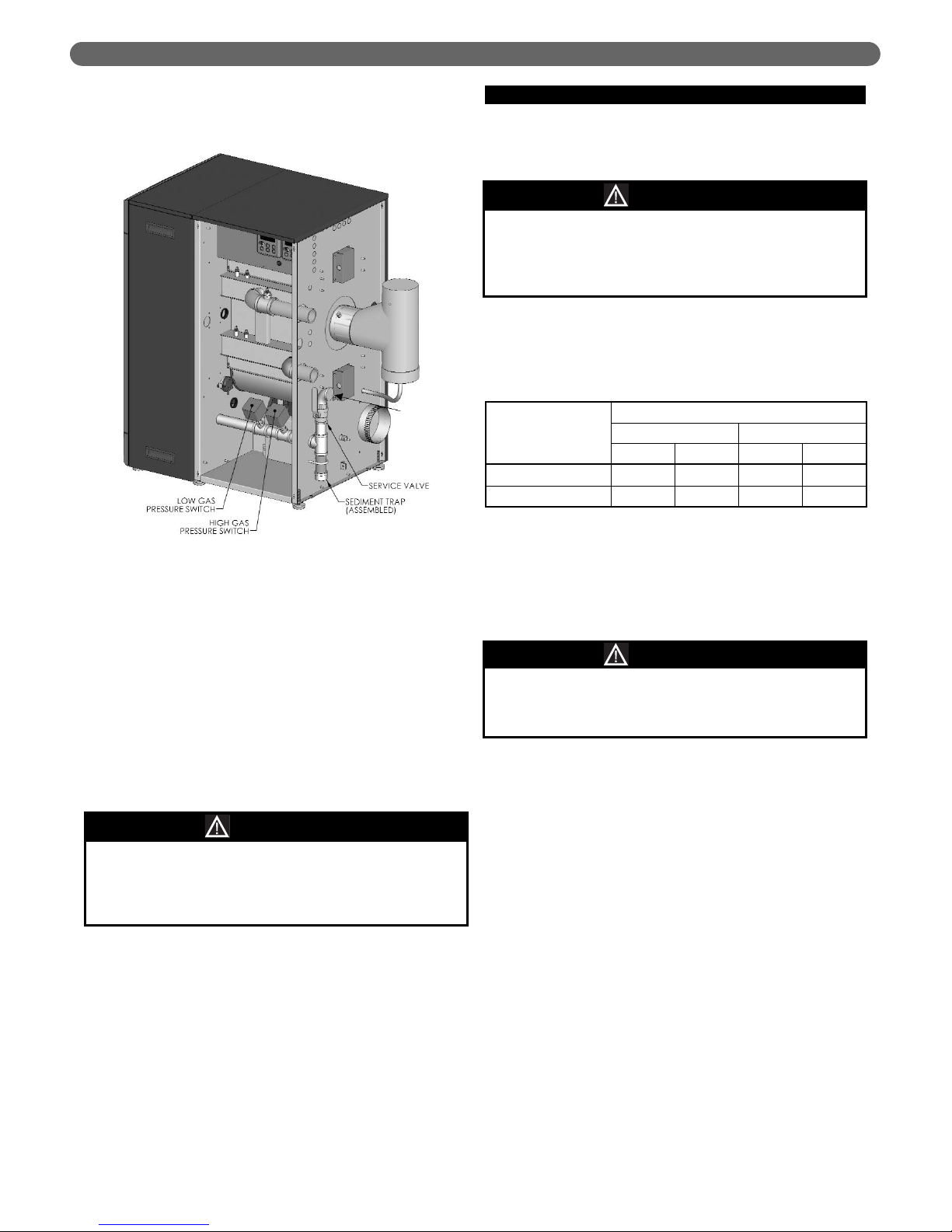
2. A sediment trap is included from the factory into the
supply piping at the boiler. Figure 5.1 shows the
sediment trap at the rear of the boiler near the base.
3. High and low gas pressure switches are provided on
the gas supply header inside the boiler cabinet. Figure
5.1 shows the pressure switch location.
4. Install the service valve, supplied by the factory, as
shown in Figure 5.1 on the inlet to the boiler gas
piping.
5. Install a ground joint union upstream of the service
valve to allow service to the appliance.
6. Maintain a minimum distance of 5 feet between the
supply gas pressure regulator and the appliance.
7. Check all gas piping for leaks prior to placing the
boiler in service. Use an approved gas detector, noncorrosive leak detection fluid, or other leak detection
method to determine if there are leaks in the system.
If leaks are found, turn off the gas flow at the service
valve and repair as necessary.
8. Gas shutoff valves, located in the blower vestibule
cabinet area, are provided for each individual burner.
These valves are to be used in addition to the gas
service valve to interrupt gas flow to the individual
burners.
D. GAS SUPPLY PIPING - OPERATION
1. The gas line must be properly purged of air to allow
the boiler to operate properly. Failure to do so may
result in burner ignition problems.
2. Table 5.4 shows the maximum and minimum fuel gas
supply pressure to the boiler.
a. Gas pressures below 3.5 in. w.c. may result in
burner ignition failures and hard ignitions. A low
gas pressure switch has been provided with the
boiler to prevent low pressure conditions.
b. Gas pressures above 26 in. w.c. may result in
damage to the automatic gas valve.
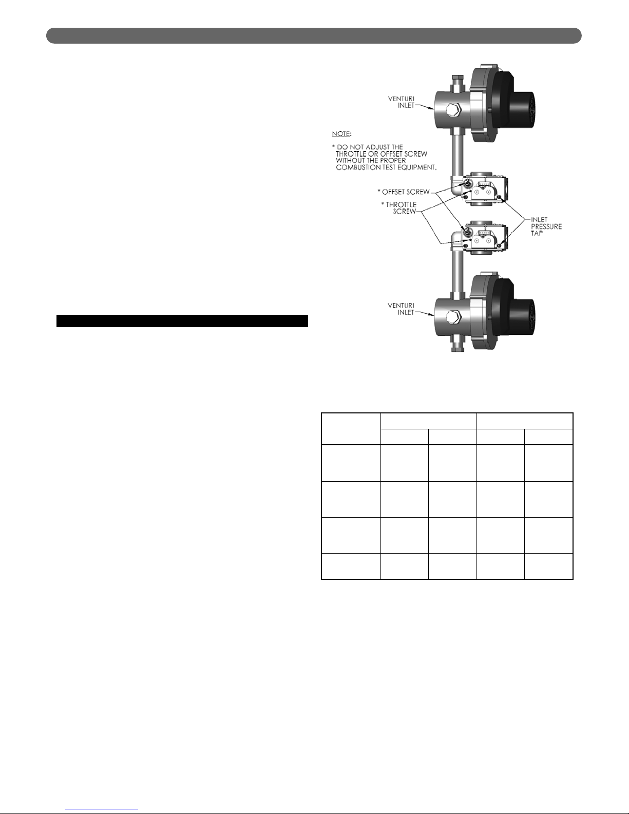
3. To check the gas supply pressure to the gas valve:
a. Turn off the power at the service switch.
b. Close the gas shutoff valve for the automatic valve
being checked.
c. Using a flat screwdriver, turn the screw inside the
inlet pressure tap fitting (see Figure 5.2) one turn
counterclockwise.
d. Attach the tube from the manometer to the inlet
pressure tap fitting.
e. Turn on the burner service switch.
f. Open the manual gas valve and start the boiler.
g. Read and record the gas pressure while the boiler
is firing.
h. Remove the call for heat and allow the burner to
shutdown normally with a full postpurge.
i. Turn off the burner service switch and close the
gas shutoff valve.
j. Remove the manometer tube from the inlet
pressure tap fitting.
FUEL PIPING
When checking for leaks, do not use matches,
candles, open flames or other methods that provide
an ignition source. This may ignite a gas leak
resulting in a fire or explosion.
WARNING
Do not subject the gas valve to more than 26 in. w.c.
(65 mbar) of gas pressure. Doing so may damage the
gas valve.
CAUTION
Fuel Type
Fuel Inlet Pressure (Main Gas Shutoff)
Minimum Maximum
in. w.c. mbar in. w.c. mbar
Natural Gas 3.5 8.5 26 65
LP Gas 3.5 8.5 26 65
Table 5.4: Maximum and Minimum Fuel Supply
Pressure
Figure 5.1: Gas Supply Pipe and Shutoff
Liquefied Petroleum (LP) Gas or Propane is heavier
than air and, in the event of a leak, may collect in low
areas such as basements or floor drains. The gas
may then ignite resulting in a fire or explosion.
WARNING
Page 29
27
k. Turn the internal screw clockwise to close the
valve.
l. Turn on the gas shutoff valve and the boiler
service switch.
m. Start the boiler and check for fuel gas odor
around the gas valve. If an odor is evident, check
to make sure that the pressure tap fitting is closed.
n. Repeat this procedure on the second gas valve.
4. All gas piping must be leak tested prior to placing the
boiler in operation.
a. If the required leak test pressure is higher than 26
in. w.c., the boiler must be isolated from the gas
supply piping by closing the service valve.
b. If the gas valve is exposed to pressure exceeding
26 in. w.c., the gas valve must be replaced.
5. Install the boiler such that the gas ignition system
components are protected from water (dropping,
spraying, rain, etc.) during operation and service
(circulator replacement, condensate collector and
neutralizer clean out, control replacement, etc.).
E. MAIN GAS VALVES - OPERATION
1. Figure 5.2 is an illustration of the main gas valve,
venturi and blower assembly for the P
UREFIRE
®
boiler.
2. Do not make adjustments to the gas valve without
instrumentation to measure carbon dioxide (CO
2
) and
carbon monoxide (CO) emissions in the exhaust vent
pipe.
3. Turning the throttle screw clockwise will decrease the
gas flow (decreasing CO
2
) and turning it
counterclockwise will increase the gas flow rate
(increasing CO
2
). Markings adjacent to the throttle
screw show + and – indicating this operation.
a. Throttle adjustments should be made only at full
input rate with the other burner off.
b. The exhaust emissions should be checked with
both burners in operation to assure correct
operation.
c. See Section 9, Start-Up Procedure for specific
information about commissioning and adjusting
the boiler.
4. The recommended CO
2
settings are given in Table
5.5. In no case should the boiler be allowed to
operate with CO emissions higher than 150 ppm.
5. Refer to Section 3, Venting and Air Inlet Piping for
information on obtaining exhaust vent samples from
this boiler.
FUEL PIPING
Figure 5.2: Gas Valve, Venturi and Blower Assembly
Natural Gas Propane (LP)
Low Fire High Fire Low Fire High Fire
Carbon
Monoxide
(CO)
< 50 ppm < 100 ppm < 50 ppm < 100 ppm
Carbon
Dioxide
(CO
2
)
8.8% to
10.0%
8.5% to
9.5%
9.8% to
11.0%
9.5% to
10.5%
Excess
Oxygen
(O
2
)
3.4% to
5.4%
4.2% to
6.0%
4.2% to
6.0%
4.9% to
6.5%
Excess Air
17.3% to
31.0%
22.4% to
35.8%
22.4% to
35.8%
27.3% to
40.1%
Table 5.5: Recommended CO2Settings
Page 30
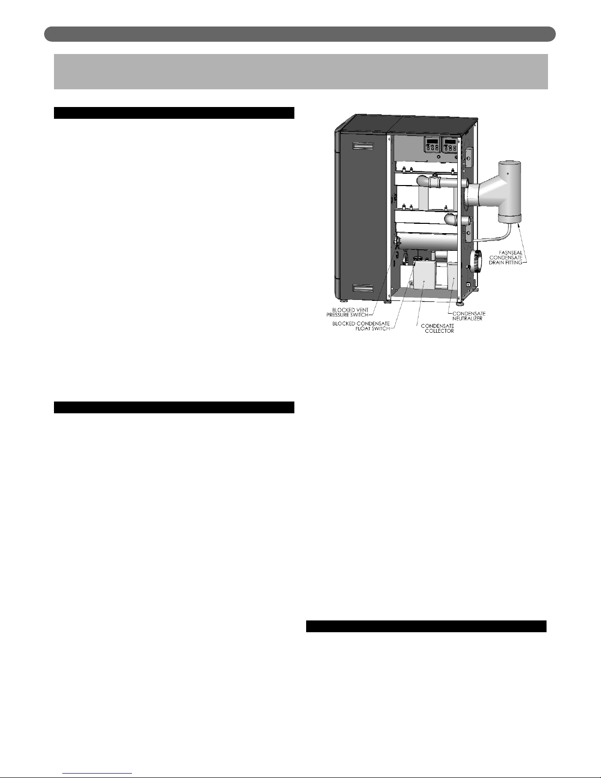
28
A. GENERAL
1. The disposal of all condensate into public sewage
systems is to be in accordance with local codes and
regulations. In the absence of such codes, follow these
instructions.
L'élimination de tout condensat dans les systèmes
d’évacuation publics des eaux usées doit s’effectuer
conformément aux codes et règlements en vigueur.
Si ces codes font défaut, suivre alors ces instructions.
2. Proper piping and removal of condensation from
combustion is critical to the operation of a condensing
appliance. Follow these instructions carefully to assure
that your P
UREFIRE
®
boiler operates correctly.
Pour le bon fonctionnement d’un appareil à
condensation, l'installation d'une tuyauterie adéquate
et la bonne évacuation de la condensation de la
combustion sont indispensables au fonctionnement
d’un appareil à condensation. Suivre attentivement
ces instructions pour assurer le fonctionnement
optimal de la chaudière P
UREFIRE
®
.
3. Depending on several factors, the condensate from
gas fired condensing appliances may have a pH value
as low as 2.5 (similar to cola soft drinks). Some local
codes require the use of neutralization equipment to
treat acidic condensate.
B. CONDENSATE SYSTEM
1. The condensate system for the PUREFIRE®PF-850 and
PF-1000 is designed to:
a. Prevent condensate from backing up into the heat
exchanger
b. Trap the condensate to prevent combustion gases
from escaping
c. Neutralize acidic condensate
2. Figure 6.1 shows the components of the condensate
system.
a. Condensate Collector Container: This vessel is a
transparent plastic container designed to catch the
condensate separately from the heat exchanger
and from the exhaust venting system. This vessel
also acts as part of the trap to prevent combustion
gases from escaping. The container is fitted with a
blocked condensate float switch.
b. Blocked Condensate Float Switch: This switch will
cause a blocking error on the boiler control and
prevent the boiler from operating if the level of
condensate in the vessel becomes too high. High
condensate levels can occur as a result of a
blocked condensate drain or similar problem.
c. Condensate Neutralizer Container: This
transparent vessel completes the trap system. It is
also designed to hold the condensate neutralizing
media that is supplied with the boilers. Open the
screw cap and put neutralizing media into the
container. The amount of media consumed
depends on the acidity and amount of condensate
produced. This vessel should be checked
occasionally to determine if additional media is
required. Neutralizing media is available from your
PB Heat Distributor in 1 lb packages (#54159).
d. Blocked Vent Switch: A blocked vent switch is
connected to the condensate system to shut the
burner down in case of a vent blockage. The
switch will trip if the pressure in the combustion
chamber exceeds 4.5" w.c. (11 mbar) and will
prevent the boiler from continuing to operate with
the condensate trap emptied due to high pressure.
e. FasNSeal Condensate Drain Tee: The condensate
drain tee, included in a separate box inside the
crate, drains condensate to the trap and
neutralization system separately from the heat
exchanger. This prevents dirt and debris from the
venting system from entering the heat exchanger.
C. CONDENSATE DRAIN PIPING
1. Material: The condensate drain is to be piped using
PVC, polypropylene, or other material resistant to
acidic condensate. Do not use steel, brass, or
galvanized pipe for this purpose. The acidic condensate
will attack most metals and cause corrosion.
CONDENSATE TRAP & DRAIN SYSTEM
6. CONDENSATE TRAP & DRAIN SYSTEM
Figure 6.1: Condensate Trap System
Page 31

29
2. Tubing Size: The connection at the rear of the heat
exchanger is designed for connection to 3/4" ID PVC
or similar tubing. Do not reduce the size of the
condensate drain tubing.
3. Tubing Pitch: Be sure that the pipe or tubing is pitched
away from the boiler with a slope of no less than 1/4"
per foot.
4. Multiple Boilers: Condensate drain tubes from
multiple boilers should be run separately to prevent a
nuisance lockout of multiple boilers due to a single
clogged drain tube.
5. Condensate Pumps: If the boiler drain is above the
level of a gravity drain, a condensate pump should be
used. Table 6.1 lists several available brands. Contact
your PB Heat, LLC Distributor for availability.
CONDENSATE TRAP & DRAIN SYSTEM
Brand Name Model Number
ITT Bell & Gossett LS
Little Giant VCMA-15UL
Beckett CB151LSUL
Hartell KT-15-1UL
Table 6.1: Recommended Condensate Pumps
Page 32

30
A. GENERAL
This appliance is to be wired in accordance with local
codes and regulations as defined by the Authority having
jurisdiction. In the absence of such local codes, the
P
UREFIRE
®
boiler is to be wired in accordance with the latest
edition of the National Electrical Code, ANSI/NFPA 70.
The boiler must be electrically bonded to ground in
accordance with the requirements of the authority having
jurisdiction or, in the absence of such requirements, with the
National Electrical Code, ANSI/NFPA 70, and/or the
Canadian Electrical Code Part I, CSA C22.1, Electrical Code.
B. CUSTOMER CONNECTIONS
1. Electrical knockouts are provided on the rear panel of
the PF-850 and PF-1000 boiler to connect supply
wiring, circulator wiring, external controls, and/or
external sensors. Figure 7.1 shows these knockouts.
a. There are (5) 7/8" diameter knockouts for line
voltage connections such as supply wiring, circulator
wiring and low water cutoff (LWCO) wiring.
b. There are (4) 7/8" diameter knockouts for low
voltage connections such as outdoor sensors,
domestic hot water (DHW) tank sensors and
system sensors.
2. Electrical terminals are located behind the control
cabinet cover plate where the Burner LCD Displays
are mounted (See Figure 7.1).
a. The cover plate can be removed by removing the
single sheet metal screw on the lower center of the
panel. The top of the panels is supported by tabs
into the top of the cabinet enclosure.
b. The terminal strips can be removed by gently
pulling them away from the wired blocks. This
allows the installer to attach wires to the connector
before plugging the terminal strip into the
mounted block.
3. Figure 7.2 shows the customer connections for the
PF-850 and PF-1000 boilers. Table 7.1 lists the
terminal numbers with nominal voltage and detailed
descriptions of the connections.
ELECTRICAL CONNECTIONS & INTERNAL WIRING
7. ELECTRICAL CONNECTIONS &
INTERNAL WIRING
Figure 7.1: Electrical Terminal Access
Table 7.1: Terminal Description
Termi na l
Input/
Output
Voltage Description
1
Output 24 VAC
CH Thermostat, Boiler Output from Zone
Control Panel, or Zone Valve End
Switches.
2
3
Output 5 VDC
Outdoor Sensor (12 kW NTC Thermister) –
To be located outside the building (north
side in the shade).
4
5
Output 5 VDC
DHW Sensor (12 kW NTC Thermister) or
DHW Tank Thermostat.
6
7
Input/
Output
24
VDC
Master Communication Link – Wire to
terminals 9 & 10 on each Dependent
Boiler.
8
9
Input/
Output
24
VDC
Dependent Communication Link – Wire to
terminals 7 & 8 on Master Boiler and 9 &
10 on more Dependent Burners.
10
11
Output
24
VAC
Remove jumper to wire to external limit
controls such as Low Water Cutoff,
Damper or Power Vent Interlocks.
12
13
Output
5
VDC
System Sensor (12 kW NTC Thermister) –
To be located on the system supply header.
14
15 (-)
Input
0-10
VDC
External analog input for boiler target
setpoint temperature from Building
Management System (BMS).
16 (+)
17
Output
120
VAC
DHW Circulating Pump – Use this output
to power the domestic hot water (DHW)
circulator (Limited Priority).
18
19
Output
120
VAC
CH Circulating Pump – Use this output to
power the central heating (CH) circulator.
20
21
Output
120
VAC
GEN Circulating Pump – Use this output
to power the GEN (Boiler) circulator.
22
23
Input
120
VAC
120 VAC, 60 Hertz, 1 Phase supply from a
fused disconnect switch to power the boiler
controls and blowers.
24
25
Output
120
VAC
Line voltage output for probe-type low
water cutoff (LWCO) power.
26
27
Input
120
VAC
120 VAC, 60 Hertz, 1 Phase supply from a
fused disconnect switch to power the boiler
circulators.
28
29
N/A Ground Earth ground.
30
31
Dry Contacts
Alarm contacts (Operation may be
changed from the Installer Menu to allow
common venting of multiple boilers).
32
Page 33

31
C. ZONE CIRCULATOR WIRING
1. Wiring for a typical circulator zone panel is shown in
figure 7.3.
2. Note that the jumper between the hot leg of the
supply (H) and the zone circulator power input (ZC)
must be removed. Then a wire from terminal 19 of
the main panel will power all of the zone circulators.
3. If the total current rating of all of the zone pumps
exceeds 10 amps, an isolation relay must be used.
D. INTERNAL WIRING
Figure 7.4 shows the complete boiler wiring schematic for
PF-850 and PF-1000 boilers. The following is a list of
internal wiring components and a short description of each:
1. User Interface Pixel Display: A single user interface
display is located on the front of the boiler behind the
smoked lens on the jacket front panel. This interface
provides information on the boiler system and allows
the user to set the boiler address for cascade systems.
2. Installer Interface Displays: The installer interface
display allow the installer or service contractor to
display status information for many different values.
These displays also allow the installer/contractor to
change settings to optimize system efficiency and
operation. A detailed description of the status and
settings available is provided in Section 8 of this
manual.
3. Interface Module: This component provides the
following functions:
a. Alarm Contacts
: These dry contacts can be used
to connect to an alarm bell, auto-dialer or other
device to alert personnel in the event of a blocking
or lockout error.
b. Analog Input
: This allows a 0-10 VDC input for
external control of the system setpoint.
c. Modbus Communication
: This provides two way
communication using Modbus interface for
external control of the setpoint and feedback of
system temperatures, error codes and other
values.
ELECTRICAL CONNECTIONS & INTERNAL WIRING
Figure 7.3: Typical Zone Circulator Relay Wiring
Figure 7.2: Customer Connection – PF-850 & PF-1000
Page 34

32
ELECTRICAL CONNECTIONS & INTERNAL WIRING
Figure 7.4: Internal Wiring Schematic for PF-850 & PF-1000
Page 35

33
ELECTRICAL CONNECTIONS & INTERNAL WIRING
4. Relay Module: This fused module provides isolation
for the pump contacts on the main control board. The
maximum rating for each pump attached is 10 amps.
Since only two pumps will operate at any one time,
this limits the incoming power required for this
module to 20 amps. This separate power supply is to
be connected to terminals 27 and 28 on the right
terminal strip.
5. Integrated Primary Controls: There are two primary
ignition controls on the P
UREFIRE
®
PF-850 and
PF-1000 boiler. They are integrated controls that
supervise all of the ignition timing as well as the
burner modulation. The “managing burner” control is
located in the blower vestibule area and is mounted
adjacent to the top, “managing burner”. The
“dependent burner” control is located adjacent to the
lower “dependent burner.
6. Supply Temperature Sensors: The supply temperature
sensors provide input to their respective control which
use them to determine the input rate of each burner.
These sensors are 12kW NTC thermistors.
7. Return Temperature Sensor: The return temperature
sensors provide information on the boiler return water
temperature to prevent unsafe operation of the boiler.
These sensors are 12kW NTC thermistors.
8. Header Temperature Sensor: The header temperature
sensor provides the outlet supply temperature of the
boiler to the managing control to control the overall
boiler system operation. These sensors are 12kW NTC
thermistors.
9. Flue Temperature Sensor: The 12kW flue temperature
sensor provides the exhaust vent temperature to the
managing control to prevent unsafe operation of the
boiler.
10. Supply Limit Switches: The supply limit switches are
UL353 certified temperature switches that prevent the
boiler from exceeding 210°F (99°C) which is the
maximum operating temperature allowed by ASME
Boiler and Pressure Vessel Code, Section IV. These
switches along with the manual reset circuitry of the
primary controls meet the high limit requirements of
ASME CSDAFB (CSD-1).
11. Thermal Fuses: The thermal fuses located at the rear
of each combustion chamber prevent unsafe
operation of the boilers in the event of ceramic
deterioration in the combustion chamber target wall.
12. Condensate Drain Float Switch: This switch is
connected to the managing primary control and
prevents the boiler from operating if the condensate in
the condensate collector vessel exceeds its maximum
level.
13. Blocked Vent Pressure Switch: This switch is
connected to the managing primary control and
prevents the boiler from operating if the pressure in
the combustion chamber exceeds 4.5 in. w.c. (11
mbar). This will prevent the boiler from operating with
the condensate displaced from the trap due to
pressure.
14. Flapper Proof-of-closure Switches: These switches
transmit the position of the flapper to their respective
primary control. If the switch indicates that the flapper
is not closed on the inactive burner while the other
burner is operating, it will start the blower for the
inactive burner. This will assure a positive combustion
chamber pressure and prevent combustion gases from
back-feeding through the inactive burner in the event
of a flapper failure.
Page 36

34
BOILER CONTROL: OPERATION
8. BOILER CONTROL: OPERATION
A. IGNITION SEQUENCE
Figure 8.1 shows the ignition sequence for the PUREFIRE
®
boiler control. Table 8.1 describes each step in the
sequence in detail. The P
UREFIRE
®
boiler control provides
dual sensing of the flame to maximize the reliability. The
control senses the burner flame with both the flame
sensor and the ignition electrode.
Figure 8.1: Ignition Cycle – Graphical Representation
Table 8.1: Ignition Sequence
Period Demand Status Burner LCD Display
Standby
No demand is present
If the power is on to the PUREFIRE®boiler and there is no heat demand, the burner LCD will display “Standby” and show the
boiler supply temperature in the lower right corner. The time, in 24 hour format, is shown in the upper right. When a heat demand
(either CH or DHW) is present, the boiler begins the ignition cycle.
Pre Purge
A CH or DWH demand must be present to initiate ignition.
Once initiated the boiler will light.
When a demand is present, the PUREFIRE®control starts the combustion air fan. The fan speed then increases to ignition speed
and the burner LCD displays the source of the call for heat along with “Trial for ignition.” This screen is displayed until the
burner is lit and stable or until a fault occurs. Once the ignition sequence begins it will continue through ignition even if the
demand has ended.
Igntion Cycle
Safety On/Off
Standby
Pre-Purge
Pre-Ignition
Ignition
Burner On
Demand
Fan
Pump
Gas Valve
Ignitor
Flame Signal
Maximum 24 hours
2 seconds
4 seconds
5 seconds
2 seconds
320 milliseconds
Purge
Post Purge 1
maximum
10 seconds
Post Purge 2
minimum
30 seconds
Circulator Post
Depends on
boiler settings
State
On
Off
High
Ignition
Low
Off
On
Off
On
Off
On
Off
On
Off
Page 37

35
BOILER CONTROL: OPERATION
Table 8.1: Ignition Sequence (cont’d)
Period Demand Status Burner LCD Display
Safety
On/Off
A heat demand has no influence in the Safety On/Off period.
The Safety On/Off step will continue even if the demand
has ended.
This step very quickly opens and closes the gas valve relays and determines if the control is operating correctly. The CH pump is
turned off during this test.
Pre-
Ignition
A heat demand has no influence in the Pre-Ignition period.
Once the internal check is complete, the control begins a Pre-Ignition sequence. The igniter is energized while the gas valve
remains off. If a flame is detected at the end of the pre-ignition period a lockout will occur.
Ignition
A heat demand has no influence in the Ignition period.
The following displays occur on ignition failure only.
The igniter remains energized for the first 4 seconds of the Ignition period. For the final 2 seconds of the Ignition period, the igniter
is turned off and the control checks for a flame signal through both the ignition electrode and the flame sensor. If no flame signal is
present at the end of the Ignition period, the control initiates a post-purge and then begins the ignition cycle again. If the number of
ignition failures exceeds the allowable number in one call for heat, the control will post purge and lock out. If the “One Hour Retry”
parameter is set to, “ON”, the control will retry ignition one hour after an ignition failure. The control records 4 flame signal values
during the last two seconds of this period that can be accessed from the “Installer Menu” under “Status”.
Burner On
A heat demand must be present for the control to stay in
this period.
Once a flame signal is established, the burner will run until a demand is satisfied, the setpoint is exceeded, or a blocking/lockout
error occurs. The maximum run period for the burner is 24 hours. If the boiler runs continuously for 24 hours, the control will
override the demand and turn off the burner. After this a restart will occur and the burner will continue to run.
Post
Purge 1
After the Post Purge period begins, a heat demand will be
ignored until after this period.
The following screen is displayed when the demand has ended.
During post purge 1, the control monitors the flame signal to be sure that the flame has extinguished. If a flame is detected after
the maximum 10 second time period, a control lockout will occur.
Post
Purge 2
During this period a heat demand has no effect on operation.
The following screen will be displayed if the supply temperature
exceeds the target setpoint.
During this period, the combustion air fan runs at high speed to purge combustion gases from the heat exchanger. The default fan
post purge period is 30 seconds. It is adjustable up to 120 seconds.
Pump
Purge
No heat demand is present.
The operation of the circulators and the boiler depend on the pump mode and the heat demand status.
Page 38

36
B. STATUS DISPLAY
The PUREFIRE®boiler display screens are designed to
provide the user and installer with useful information
about the boiler function. The PF-850 and PF-1000
boilers have three different display screens available.
1. Master Pixel Display: This display is located behind
the smoked lens at the top of the boiler front panel.
Removing the lens allows access to the display.
2. Managing Burner LCD Display: This display is located
on the right side of the boiler behind the heat
exchanger side panel. The managing burner display is
located toward the front of the boiler and controls the
upper burner assembly.
3. Dependent Burner LCD Display: This display is
located on the right side of the boiler behind the heat
exchanger side panel. The dependent display is
toward the rear of the boiler and controls the lower
burner assembly.
BOILER CONTROL: OPERATION
Table 8.2: Initialization Screens
Figure 8.2: Pixel Display Illustration
Initialization
Screens
Pixel Displays LCD Displays
The software version indicated by [ x x x x ] indicates the
version of the program for the display interface.
Initialization screens are displayed for the first few seconds after power is applied to the front Pixel display and both burner
LCD displays.
Page 39

37
BOILER CONTROL: OPERATION
Table 8.3: Display Screens Under Various Conditions
Pixel Displays LCD Displays
Standby
Managing (Boiler—Pressing the up or down key
displays the boiler system information)
Dependent
Central Heating
(CH) Demand
Managing (Boiler)
Dependent
Domestic Hot
Water (DHW)
Demand
Managing
Dependent
Supply at
Setpoint
Special Demand
Functions
Page 40

38
BOILER CONTROL: OPERATION
Pixel Displays LCD Displays
Service
Notification
Pixel Displays Dependent LCD Displays
Error Handling
Managing LCD Display
Table 8.3: Display Screens Under Various Conditions (cont’d)
Pixel Displays LCD Displays
Ignition
Failure Error
Handling
Flame
Failure Error
Handling
Ignition Retry
Page 41

39
BOILER CONTROL: OPERATION
C. USER MENU
To access the user menu for each burner, simply press the
“Menu” key on the corresponding managing or
dependent LCD display located on the right side of the
boiler behind the heat exchanger access panel. The
managing display is on the left and corresponds to the
upper burner. The dependent display is on the right and
corresponds to the lower burner. Use the “L” and “
M”
keys on the display to move the cursor to the desired
selection. Pressing “Select” will access the submenu for
the selection. The submenus are described in detail below.
1. LCD Status Menu
Status Menu
: The user status menu gives the user or
installer access to basic information about the boiler
system. The first screen shows the Current Supply
Setpoint. If the boiler is in CH Mode 0, 2 or 6, this is
the temperature that the boiler targets. As the boiler
approaches this target, the burners will modulate their
input.
The next screens show temperature values read by the
temperature sensors in the control system. The supply
and return temperatures are measured at the header
on the outlet side of the heat exchanger. There is a
supply and return sensor for each burner. In addition
to the supply and return sensors, there is a header
(system) sensor on the boiler supply (outlet) pipe.
Typical Values for Water Sensors:
(Supply/Return/System/DHW): 70°F (21°C) to 200°F
(93°C).
A value of 14°F (-10°C) indicates an open sensor and
a value of 244°F(118°C) indicates a short for these
sensors.
Typical Values for the Vent Sensor are: 70°F (21°C) to
200°F (93°C).
A value of 50°F (-10°C) indicates an open sensor and
a value of 244°F(118°C) indicates a short. Since
boilers installed in low temperature environments such
as a garage may experience vent temperatures below
50°F, the control works as follows:
a. If the Vent Temperature Sensor reads less than
50°F, the boiler will continue to operate normally,
unless,
b. If the return temperature exceeds 80°F (27°C) or
the supply temperature exceeds 120°F (49°C) the
burners will operate at their minimum modulation
until the call for heat ends or the vent temperature
exceeds 50°F.
The outdoor sensor temperature should correspond to
the current outdoor temperature. If the sensor is
mounted in direct sunlight or near an appliance
exhaust vent, erratic operation can result due to large
changes in the apparent outdoor temperature.
A value of -40°F (-40°C) indicates an open sensor and
a value of 244°F(118°C) indicates a short for this
sensor.
The final screen of the status menu provides
information on the status of each of the circulators.
Since these circulators on the PF-850 and PF-1000
boilers are connected to the managing burner, only
the statuses of these circulators are of interest.
2. LCD Settings Menu
The user settings menu provides access to basic
settings on the P
UREFIRE
®
control. After choosing the
“Settings Menu” the Central Heating Setpoint menu
appears. To access the other menus, press the
M key.
Some of the menus shown below will not appear
depending on the CH or DHW mode chosen.
a. Central Heating Setpoint
: Depending on the CH
Mode chosen (in the Installer Menu), the user may
be able to adjust the boiler water temperature that
is targeted by the control on a central heat
demand. If the CH Mode is 1 or 2 (Outdoor
Reset), this screen will show “OD RESET” along
with the target temperature calculated by the
control algorithm. The user is not allowed to
override the calculated temperature. If CH Mode 0
or 6 is chosen, the target temperature can be
changed by pressing the “Select” key and using
the “L” and “
M” keys to increase or decrease the
value. The following shows the range and default
values for the Central Heating Setpoint.
Figure 8.3: User Menu
Figure 8.4: Status – Supply Setpoint
Figure 8.5: Status – Temperature
Figure 8.6: Status – Circulators
Figure 8.7: Settings – CH Setpoint
Page 42

40
BOILER CONTROL: OPERATION
b. DHW Boiler Setpoint: This value determines the
target temperature for the boiler supply to an
indirect domestic hot water (DHW) storage tank.
This should not be confused with the DHW Tank
temperature. If the DHW Mode is set to Mode 0
(No DHW) this screen will not be visible.
c. DHW Tank Setpoint
: This screen allows the user
to select the target temperature for the indirect
DHW storage tank. This screen is only visible if
the DHW Mode is set to Mode 1 (DHW Tank with
Sensor) and an optional 12 kW DHW Tank sensor
is purchased (PB Stock Code 54157).
d. Time & Date
: This screen allows the user to set
the current date & time for the burner. Setting the
current date and time allows the installer to set up
alert messages for routine inspection and
maintenance.
•
Press the “Select” key. The third line will
alternately flash the day of the week and “---”.
•
Use the “” and “” keys to change the day.
Press the “Select” key to select the correct day.
•
The date value will flash. Use the “” and
“” keys to change the date. Press the
“Select” Key.
•
The month value will flash. Use the “” and
“” keys to change the month. Press the
“Select” Key.
•
The year value will flash. Use the “” and
“” keys to change the year. Press the
“Select” Key.
•
The hour value will flash. Use the “” and
“” keys to change the hour. Press the
“Select” Key. (Note that the hour is displayed
in the 24 hour format so that 3:00 pm =
15:00.)
•
The minute value will flash. Use the “” and
“” keys to change the minutes. Press the
“Select” Key.
The date and time will be stored in non-volatile
memory so the date will not require resetting if the
power is disconnected.
e. Temperature Units
: This screen allows the user to
change the temperature unit display. The default
units are Fahrenheit °F. To change the unit display,
press the “Select” key. The current unit system will
flash. Use the “” and “” keys to change the
value to Celsius °C. Press the “Select” key again
to choose the units.
3. LCD Message Menu
The messages menu allows the user to view the last
blocking error or last lockout error. The display will
also show the interval between the last blocking or
lockout error and the error before the last. To
determine the interval between the current time and
the error displayed, create an error by disconnecting
the supply sensor wire.
WARNING
DANGER
Water temperatures over 125°F can instantly cause
severe burns or death from scalding. Children, elderly
and disabled individuals are at the highest risk of
scalding. See instruction manual for the indirect tank
before setting the water heater temperature. Instruct
users to feel the water temperature before bathing or
showering. Anti-scald valves are recommended.
Figure 8.8: Settings – DHW Boiler Setpoint
Figure 8.9: Settings – DHW Tank Setpoint
Figure 8.10: Settings – Date & Time
Figure 8.11: Settings – Temperature Units
Table 8.4: CH Setpoint Range & Defaults
Central
Heating
Setpoint
Minimum Maximum Default
50°F 195°F 160°F
10°C 91°C 71°C
Table 8.5: DHW Boiler Setpoint Range & Defaults
DHW Boiler
Setpoint
Minimum Maximum Default
122°F 195°F 180°F
50°C 91°C 82°C
Table 8.6: DHW Tank Setpoint Range & Default
DHW Tank
Setpoint
Minimum Maximum Default
50°F 158°F 120°F
10°C 70°C 49°C
Be sure to only use the 12 kW tank sensor indicated.
Other sensors will not provide accurate tank
temperatures and may cause severe personal injury
due to scalding.
DHW Boiler Setpoint Setting is only available in DHW
Mode 1 & 2.
NOTICE
DHW Tank Setpoint Setting is only available in DHW
Mode 1.
NOTICE
Page 43

41
BOILER CONTROL: OPERATION
a. Last Lockout Error: The last lock menu allows the
user to view the reason for the last lockout. See
Table 10.2 for a list of locking errors and the
associated codes. Note that a value of #255
indicates that there are no lockout errors in the
control history. Also, note that the errors displayed
may have occurred during the factory fire test or
field commissioning of the equipment.
b. Last Blocking Error
: The last block screen allows the
user to view the reason for the last blocking error.
See Table 10.1 for a list of blocking errors and the
associated “E” codes. Note that a value of #255
indicates that there are no blocking errors in the
control history. Also, note that the errors displayed
may have occurred during the factory fire test or
during field commissioning of the equipment.
D. INSTALLER MENU
1. Menu Overview
The installer menu allows installing or service
contractors to view and/or make adjustments to the
permanent boiler settings based on the installation
configuration, desired operation and local codes. The
menu structure is shown in Figure 8.13.
To access the installer menu, press and hold the
“Menu” and “Select” key on the LCD display
corresponding to the burner on which the parameter
change is to be made.
a. Managing Burner (Burner M)
: The top burner on
each PF-850 or PF-1000 boiler is designated as
“Burner M” or “managing burner”. This burner
control is connected to the GEN (Boiler) circulator,
the CH and/or DHW circulator* and all external
sensors*. In the following section, all parameters
which affect only the managing burner will be
designated with “(M)”.
*Stand-Alone configuration or Master Boiler
in multiple boiler configuration.
b. Dependent Burner (Burner D)
: The bottom burner
on each boiler is designated as the “Burner D” or
“dependent” burner. This burner control is started
and stopped by the managing burner only. Its
operation is not affected by external inputs.
2. Status
The status menu is designed to monitor key
parameters and aids the installer or service contractor
in determining if there are problems with boiler
operation.
a. Current Supply Setpoint
: The setpoint value will
change for DHW demands or CH demands
depending on the setpoint chosen for these modes
of operation. When outdoor reset modes are
selected, this value is the calculated target for the
system.
b. Fan Speeds
: Screens #2 & #3 display fan speed
information. The current fan speed will vary
during operation between the low power and high
power values. The Low Power, Ignition, and Hi
Power values are preset at the factory for a specific
model size. Table 12.3, in Section 12 of this
manual, shows the fan speed presets for each
model size. Note that these values may vary
slightly due to air setting changes.
c. Flame Measurements
: Screens #4, #5 & #6
display flame signal information. The first value,
Flame Signal, is the current flame rectification signal
in micro amps (µA). The minimum value for this
signal that will allow the burner to continue running
is 2.8 µA the maximum value for this is 10 µA.
Figure 8.12: Messages – Last Errors
Figure 8.13: Installer Menu
Figure 8.14: Status – Supply Setpoint
Figure 8.15: Status – Fan Speeds
Figure 8.16: Status – Flame Signal
Page 44

42
BOILER CONTROL: OPERATION
The next value, Flame Failures, is the number of
times the burner has dropped out due to flame
failure. Several flame failures may have occurred
during the factory firetests and installation. If there
are a large number of flame failures showing on
this screen, contact your Peerless
®
Representative.
On Screens #5 and #6, the Flame Measurement
values 1-4 are logged in the last two seconds of
the most recent ignition sequence in 1/2 second
intervals. This helps service contractors to
diagnose ignition issues.
d. Ignition Attempts
: Screen #7 provides information
about ignition attempts. Obviously, the total
ignition attempts are the sum of the successful and
failed attempts. Several ignition failures may occur
during factory firetest and equipment
commissioning. However, if there are a large
number of failed ignition attempt showing on this
screen, contact your Peerless
®
Representative. If
there is an unusually large number of total ignition
attempts, there may be a problem with the boiler
short cycling.
e. Burner Run Time
: Screen #8 provides
information about the total run time of each
burner. The total burner run time is the sum of the
central heating (CH) and domestic hot water
(DHW) hours. The total boiler run time is the sum
of both burner run times.
f. Blocking Errors:
Screen #9 provides error history
about the last 16 blocking errors. Blocking errors
are errors that prevent the burner from operating
until the condition causing the error is corrected.
Sensor errors, low water, and blocked vent are
examples of this type of error. To review previous
errors, press the select key. The number in the
upper right changes from the status screen “9” to
a blinking “0” indicating that this is the most
recent error. Use the arrow keys to scroll through
previous errors from 0 to 15. If the screen shows
“#255” in the error number location, this
indicates that there is no error stored in this
location. All errors on screens higher than one
showing “#255” should also indicate no error.
Table 10.1 (in Section 10) provides a list of
blocking errors.
g. Lockout Errors:
Screen #10 provides error history
about the last 15 locking errors. Locking errors are
errors that require a manual reset on the control
board (pushing the “Reset” key on the display) to
reset the burner once the condition causing the
error has been corrected. Ignition Failure, Flame
Failure and High Limit Temperature are examples
of this type of error. To review previous errors,
press the “Select” key. The number in the upper
right changes from the status screen number “10”
to a blinking “0” indicating that the screen is
showing the most recent lockout error. If the
burner is not in lockout, this position should show
“#255” in the error number location. Use the
arrow keys to scroll through previous errors from 1
to 15. As with blocking errors, “#255” always
indicates that no error is stored in this location.
Table 10.2 provides a list of lock out errors.
3. Burner Settings
The burner settings menu allows the installation or
service contractor to change settings which effect the
burner operation. The following are descriptions of
the available settings.
a. Burner Mode
: The burner modes are set by
default from the factory. The upper burner, which
corresponds to the display closest to the front of
the boiler, is always the “managing burner”. The
lower burner, with its display toward the rear, is
always the “dependent burner”. These values are
not intended to be changed in the field.
b. Boiler Address
: The PUREFIRE®PF-850 & PF-1000
can be operated with as many as 15 identical
boilers as a cascade boiler system by adding 2
wire communication links between the boilers.
The following chart shows the role of the boiler
depending on the boiler address. Multiple boiler
operation is covered in-depth at the end of this
section of the manual. This screen is available
only on the managing burner.
Figure 8.17: Status – Ignition
Figure 8.18: Status – Burner Run Time
Figure 8.19: Status – Blocking Errors
Figure 8.20: Status – Locking Errors
Figure 8.21: Burner Settings – Burner Mode &
Boiler Address
Table 8.7: Boiler Address
Boiler Address
Value
Description
0 Stand-Alone Boiler
1 Master Boiler in a Cascade System
2-16 Dependent Boilers in a Cascade System
Managing Burner Only
Page 45

43
BOILER CONTROL: OPERATION
c. Installation Location & Vent Material: Due to
differing national codes in the United States and
Canada, there are different material requirements
for exhaust vent pipe. Therefore, the maximum
vent limit temperature is different depending on
the material used.
Screens #3 and #4 allow the installer to select the
installation location and vent material. Based on
the information given, Table 8.8 shows the
exhaust temperature that the control will allow
before reducing the burner input rate. If the
temperature of the exhaust gas approaches these
values, the control will reduce the input rate on
both burners until the temperature begins to drop.
If the flue temperature continues to rise, the
control will shut down both burners.
Note: Although stainless steel can withstand a
temperature higher than 230°F (110°C) the
temperature limit is set to this temperature since
the vent temperature should not exceed this
temperature unless there is a problem with the
heat exchanger.
d. Freeze Protection
: Freeze protection is intended to
prevent freezing the central heating system.
•
First, the control activates pumps to distribute
heat uniformly through the system.
– If the boiler supply (header) temperature
drops below the value selected for “Freeze
Protection starts at:”, the General (boiler)
circulator is activated.
– If either of the boiler return sensors reports a
value below this temperature, the CH
circulator is started.
•
Next, if Burner M return temperature drops more
than 9°F (5°C) below the “Freeze Protection
starts at:” value, the control activates Burner M
(managing burner) at it minimum rate.
– If a central heat demand is detected while the
burner is operating for Freeze Protection, the
burner will run normally to satisfy the demand.
– Finally, once the return temperature
increases to 9°F (5°C) above the chosen
value, the burner is switched off and the
pumps are deactivated.
e. Blower Postpurge Time
: The blower postpurge time
can be increased to address problems under extreme
conditions (long exhaust vent runs, high winds, etc.)
where the products of combustion are not fully
expelled from the venting system. This feature
should be used sparingly as it may lead to decreased
efficiency and higher fuel bills in certain situations.
f. Additional Safety Functions
: This feature allows
the installer to choose between using a low water
cut-off or a flow switch to assure proper water
circulation and operation of the boiler. Either of
these devices should be wired to the terminals 11
& 12 (Safety Interlocks) of the P
UREFIRE
®
PF-850
or PF-1000 boilers. Note that these terminals are
connected internally to the high & low gas
pressure switches so that a “Safety Interlock Open”
error may occur due to high or low gas pressure in
addition to anything connected to these terminals.
Figure 8.25: Burner Settings – Additional Safety
Functions
Figure 8.24: Burner Settings – Blower Post Purge
Table 8.10: Freeze Protection Range & Default
Table 8.11: Blower Post Purge Range & Default
Table 8.8: Vent Temperature Limits
Vent Material
Location
U.S.A. Canada
PVC
190°F
(80°C)
149°F
(65°C)
CPVC
230°F
(110°C)
190°F
(80°C)
Polypropylene
(PPs)
230°F
(110°C)
230°F
(110°C)
Stainless Steel
230°F
(110°C)
230°F
(110°C)
Freeze Protection
Starts at
Default Minimum Maximum
50°F (10°C) 45°F (7°C) 56°F (13°C)
Blower Post
Purge Time
Default Minimum Maximum
30 sec 30 sec 120 sec
Table 8.9: Location & Vent Material Default
Figure 8.23: Burner Settings – Freeze Protection
Parameter Default
Location U.S.A.
Vent Material PVC
Figure 8.22: Burner Settings – Location & Vent
Material
Managing Burner Only
Page 46

44
BOILER CONTROL: OPERATION
•
LowWaterCO: This is the default selection on the
control. However, no low water cut-off (LWCO)
device is supplied with the boiler. A probe-type
LWCO, such as the Hydrolevel Model 1150 or
McDonnell & Miller RB-120 should be used with
P
UREFIRE
®
boilers. Figure 8.27 shows the
recommended wiring of these devices.
•
FlowSwitch: A flow switch, such as the
McDonnell & Miller FS250, is designed to
trigger a blocking error immediately on a loss
of flow in the system. To protect from a false
flow reading on this type of device, the control
assures that the flow switch is open (indicating
no flow) before activating the General and the
CH or DHW circulator. After these pumps are
activated, it will not proceed into a trial for
ignition until the switch closes.
g. Ignition Attempts
: The control is configured from
the factory to not allow the burner to recycle after
a failed ignition attempt. At installation, the control
can be configured to allow up to 3 ignition
attempts before locking out and requiring a
manual reset. In addition, the control may be
configured to retry for ignition, one hour after
lockout without a manual reset. Check applicable
codes before changing these parameters.
h. Flame Failures
: The control is configured from the
factory to not allow the burner to recycle after a
flame failure. At installation, the control can be
configured to allow up to 2 retries after a flame
failure before locking out and requiring a manual
control reset. In addition, the control may be
configured to retry for ignition one hour after a
lockout without a manual reset. Check applicable
codes before changing these parameters.
i. Air Adjustment
: Screens #12 and #13 allow the
fan speed to be increased if required. The
following is an explanation of the conditions under
which these adjustments should be made.
j. Minimum Fan Speed
: The minimum fan speed
adjustment is intended to respond to potential
issues with the loss of flame due to pressure
fluctuations in the venting system. These concerns
may be due to wind gusts on sidewall vented
boilers or other sources of exhaust vent pressure
spikes. The minimum fan speed may be adjusted
in 30 RPM increments up to the minimum fan
speed + 540 RPM. This feature should only be
used to address nuisance flame failure or flapper
valve failure lockout errors.
Figure 8.27: Low Water Cut-off (LWCO) Wiring
Figure 8.28: Burner Settings – Flame Failures
Allowed
Figure 8.26: Burner Settings – Ignition Attempts
Allowed
Table 8.12: Ignition Attempts Ranges & Defaults
Table 8.13: Flame Failures Allowed Ranges &
Defaults
Parameter Default Minimum Maximum
Ignition Attempts
Allowed
1 1 3
Ignition Attempts
1 Hr Retry
OFF OFF ON
Parameter Default Minimum Maximum
Flame Failure
Retries Allowed
0 0 2
Flame Failure
1 Hr Retry
OFF OFF ON
Figure 8.29: Burner Settings – Air Adjustment
Page 47

45
k. Maximum Fan Speed: The maximum fan speed
adjustment is intended to compensate for long
exhaust vent runs if the boiler fails to keep up with
the required load. Since the input rate may drop
off slightly under increased resistance due to long
exhaust vent installations, the boiler input may be
incrementally increased to compensate. This
adjustment should only be made if both of the
following conditions are met:
•
The boiler is not keeping up with the required
load.
•
The input rate has been determined to be below
the rated input by timing the gas supply meter.
If these conditions are not met, contact your
Peerless
®
Representative for assistance.
l. Alarm Mode
: The alarm mode allows the installing
contractor to set the menu to the mode
appropriate for the installation. The default setting
is “Stand Alone” in which the alarm contacts
(Terminals #31 & #32) simply close if an alarm
condition exists. Figure 8.31 shows the proper
wiring arrangement for the “Common Vent” alarm
mode. In this configuration, the alarm will sound if
a boiler loses power.
4. Central Heating (CH) Settings
CH settings manage the boiler temperature and
circulators for the central heating load. Although the
menu items that follow are factory set, by default, to
values that can operate in any installation, they can
be adjusted to maximize the efficiency of this product.
The boiler can be configured to operate with a fixed
setpoint or using outdoor reset to vary the boiler
target temperature according to the load implied by
the outdoor temperature.
a. Setpoint Operation
: When using a setpoint
strategy, the boiler targets a fixed setpoint which is
set in the User Menu on the P
UREFIRE
®
control. As
the boiler supply (outlet) temperature approaches
this target, the burner begins to modulate the fuel
input, reducing the output rate of the boiler. If the
boiler reaches a temperature of 9°F (5°C) above
the setpoint before the heat demand ends, the
burner will shut down. If the heat demand
continues and the boiler temperature drops 9°F
(5°C) below the setpoint, the burner will restart.
b. Outdoor Reset Operation
: Outdoor reset strategies
are ideal for condensing boilers for two reasons:
•
Heat distribution units, such as radiators,
radiant floors and copper baseboard are sized
to deliver the heat required on the coldest day
at a set temperature. For the remainder of the
heating season, the maximum output is not
required, so the distribution can be set to a
cooler temperature.
•
Condensing boilers, like the PUREFIRE®, are
designed to withstand acidic condensate and
therefore can be operated at as low a
temperature that is reasonable. At lower
temperatures [below 120°F (49°C) return
temperature], these boilers condense more
and are more efficient.
c. CH Modes
: The CH modes allow the operator to
change the way the boiler operates to satisfy
central heating demands.
BOILER CONTROL: OPERATION
Table 8.14: Air Adjustment Ranges & Defaults
Parameter Default Minimum Maximum
Air Adjustment
Min Fan Speed
0 rpm 0 rpm 540 rpm
Air Adjustment
Max Fan Speed
0 rpm 0 rpm 540 rpm
Figure 8.31
Figure 8.30: Burner Settings – Alarm Mode
Managing Burner Only
Page 48

46
•
Mode 0, Indoor Thermostat: This is the default
mode in which the boiler responds to a
demand from an indoor thermostat or zone
control panel at terminals #1 and #2 in the
P
UREFIRE
®
control panel. The control targets a
fixed setpoint and as the boiler water
temperature approaches the target, the control
begins to reduce the fuel input. This mode
doesn’t require an outdoor sensor.
•
Mode 1, Indoor Thermostat with Outdoor
Reset: When operating in this mode, the
control uses the outdoor temperature and
installer selected data to calculate a target
boiler water temperature. A detailed
description of outdoor reset is presented later
in this section.
•
Mode 2, Permanent Demand and Outdoor
Reset: In this mode, the boiler operates to
maintain a supply (header) temperature
calculated by the outdoor reset algorithm.
The boiler operates independently of any
room thermostats. This is useful in buildings
with many zones which operate on
independent thermostats to prevent the boost
function (described later in this text) from
increasing the target temperature due to a long
sustained call for central heat resulting from
overlapping individual calls.
•
Mode 3, Permanent Demand: This mode is
similar to Full Outdoor Reset except that the
control targets a fixed setpoint instead of a
calculated setpoint based on the outdoor
temperature. Again, the boiler control operates
independently of input from room thermostats.
If a switch between terminals #1 and #2 is
closed, the target temperature will be set back
by 18°F (10°C).
•
Mode 4, 0 -10V Input to Modulate Setpoint:
This allows the boiler supply target to be set
by an external analog 0-10 volt signal. The
input for this signal is at terminals #15 & #16.
A call for heat will be generated by a signal of
1.5 VDC or higher. The setpoint for an input
voltage between 1.5 and 2.0 VDC will result in
a boiler setpoint of 68°F (20°C). An input
voltage of 10 VDC will result in a setpoint of
195°F (91°F).
•
Setback: If a switch is closed across terminals
#1 & #2, a setback of 18°F (10°C) is applied
to the calculated target temperature. This
feature is useful in a building (such as an office
building) that is unoccupied during certain
times. A switch or timer can be used to set
back the boiler target temperature during
unoccupied periods.
d. Pump Purge Time: The installer can define the
length of time that the circulators operate after the
end of call for heat. The CH and General
circulator post purge time can be set
independently. The following chart shows the
range and default values for both of these pumps.
e. Outdoor Reset
: Since heating loads are typically
lower when the outdoor temperature rises,
outdoor reset lets the installer reduce the boiler
target temperature as the outdoor temperature
increases. As mentioned above, this increases the
efficiency of the boiler. This is especially true with
condensing boilers because it helps to recover the
heat from the water vapor which, in conventional
boilers, carries valuable energy out with the
exhaust.
f. System Type Presets
: For convenience, the
P
UREFIRE
®
boiler control provides preset values for
the outdoor reset parameters based on the system
type. Table 8.17 shows the values that are applied
when different system preset types are selected. If
the system type, “User Defined” is chosen the
outdoor reset definition values may be adjusted. If
changes are made to the boiler design or mild
weather boiler temperatures, the system type is
automatically switched to, “User Defined”.
BOILER CONTROL: OPERATION
Table 8.16: Pump Purge Time Ranges & Defaults
Figure 8.33: CH Settings – Pump Purge Time
Table 8.15: CH Modes
Mode Display
Target
Temperature
Action when
Terminals #1 &
#2 Closed
0
Indoor
Thermostat
Fixed Setpoint
Call for Central
Heating
1
Indoor
Thermostat
with OD Reset
Outdoor Reset
Calculation
Call for Central
Heating
2
Permanent
Demand & OD
Reset
Outdoor Reset
Calculation
18°F (10°C)
Target Setback
3
Permanent
Demand
Fixed Setpoint
18°F (10°C)
Target Setback
4
0-10 V Input
to Modulate
Setpoint
External Analog
(0-10 VDC) Input
of Setpoint
No Effect
Circulating Pump Minimum Default Maximum
Central Heating (CH) 0 1 minute 60 minutes
General 0 1 minute 60 minutes
Managing Burner Only
Figure 8.32: CH Settings – CH Modes
Managing Burner Only
Page 49

47
BOILER CONTROL: OPERATION
g. Warm Weather Shutdown: If the boiler is set to
operate in CH Mode 1 or 2, the P
UREFIRE
®
control
is set by default to prevent the boiler from operating
to satisfy a central heat demand if the outdoor
temperature is above 70°F (21°C). This value can
be adjusted using the values shown below.
If the installer prefers to use custom values for the
outdoor reset parameters, the following provides
guidance.
h. Design Point
: The design point is defined by the
outdoor design temperature and the boiler
design temperature.
i. Boiler Design Temperature
: The boiler design
temperature is the temperature at which the boiler
is designed to operate in order to meet the load.
Copper finned tube radiators are typically rated at
180°F (82°C). The Table 8.19 shows typical boiler
design temperatures for different types of head
distribution units.
j. Outdoor Design Temperature
: The heat loss for the
structure is determined by considering the coldest
sustained outdoor temperature that is expected at
the site location. For a detailed list of outdoor
design temperatures by state, refer to the H-22
heat loss calculation guide published by AHRI.
Figure 8.35: Outdoor Reset Operation
Table 8.17: System Type Presets
System Type
Temperatures
Boiler
Design
Mild Weather
Boiler
1. Finned Tube Baseboard 180 140
2. Hydro Air Unit 190 140
3. Cast Iron Radiator 160 120
4. Cast Iron Baseboard 150 110
5. Low Mass Radiant 140 70
6. High Mass Radiant 120 70
7. user Defined (Default) 180 70
Table 8.18: Warm Weather Shutdown Range &
Default
Parameter Minimum Default Maximum
Warm Weather Shutdown 35°F (-18°C) 70°F (21°C) 100°F (38°C)
Figure 8.36: CH Settings – Reset Curve Design
Table 8.19: Reset Curve Design Ranges & Defaults
Parameter Minimum Default Maximum
Boiler Design Temp. 61°F (16°C) 180°F (82°C) 195°F (91°C)
Outdoor Design Temp. -40°F (-40°C) 0°F (-18°C) 70°F (21°C)
Managing Burner Only
Figure 8.34: CH Settings – Warm Weather Shutdown
Managing Burner Only
Page 50

48
BOILER CONTROL: OPERATION
k. Mild Weather Point: The mild weather point is
defined by the mild weather outdoor temperature
and the mild weather boiler temperature.
l. Mild Weather Boiler Temperature
: This is the
minimum temperature that the boiler will target to
satisfy a CH demand. In radiant floor design, this
temperature can be set very low. However, avoid
setting the temperature too low in systems with
limited radiator surface and in lower floors with
open stairways that can allow heat to migrate up
to higher floors.
m. Mild Weather Outdoor Temperature
: This
temperature is the highest outdoor temperature at
which the boiler is expected to run. The default
value for this is 70 which equals the default warm
weather shutdown value.
The example in Figure 8.35 shows an outdoor
temperature of 0°F (-18°C) which corresponds to
the value for Springfield, Massachusetts. The
boiler temperature is shown at 160°F (71°C) to
meet the load as determined by the system
designers. The mild weather point is at an outdoor
temperature of 70°F (21°C) and a boiler
temperature of about 85°F (29°C). When the
outdoor temperature is 32°F (0°C), the boiler will
target 130°F (54°C).
n. Boiler Limits
: The boiler limits are available to limit
the minimum and maximum temperature that the
boiler can target. Note that these limits will
override the values set in the outdoor reset design
and mild weather outdoor reset parameters.
o. Boiler Min
: The boiler will not target a temperature
lower than what is chosen in this menu screen. The
default for this is, “Off” since low temperatures will
not affect the boiler. However, it may be useful in
installations that require a minimum temperature to
operate (like a fan coil unit that will not allow a fan
to operate below a certain temperature).
p. Boiler Max
: The boiler will not target a
temperature higher than that chosen in this menu.
This can be useful to prevent damage due to high
temperatures in temperature sensitive situations
such as radiant floors.
q. Boost
: The boost function is designed to compensate
for a system that is not meeting the required load. If
there is a constant call for central heat for the length
of time specified, the target temperature will be
increased by the temperature value selected. The
boiler will never target a temperature higher than
that specified by the boiler max. parameter.
There are several reasons why the boost function
may or may not be implemented.
•
In buildings which have many zones, there may
seldom be a period when none of the zones is
calling for heat. In this case, the boiler will very
often be operating at the temperature selected
by the “boiler max.” parameter, and much of
the advantage of a condensing boiler may be
lost. Therefore, it may be better to use CH
Mode 2, “Permanent Demand and Outdoor
Reset” in these situations. In this mode, the
boost function is not applied therefore the
boiler will continue to run at the temperature
calculated by the outdoor reset algorithm.
•
Programmable thermostats can give a building
owner the ability to set back the thermostat
significantly during unoccupied periods. After
an aggressive setback, it may take the boiler a
significant amount of time to recover. However,
this may lead to the boiler frequently operating
at higher temperatures, where it is less efficient.
Before using setback thermostats, the building
owner should be made aware that aggressive
setback s of 10°F (6°C) or more may not have
the desired effect.
•
If the outdoor reset parameters are set for
design conditions at a certain outdoor design
temperature, and the outdoor temperature
drops below that temperature for a significant
amount of time causing cold indoor
temperatures, the boost function can allow the
boiler to target temperatures up to the boiler
maximum to satisfy the load.
Table 8.21: Reset Curve Min/Max Ranges & Defaults
Figure 8.39: CH Settings – Temperature Boost
Table 8.22: Temperature Boost Ranges & Defaults
Parameter Minimum Default Maximum
Boost Temperature 0°F (0°C) 18°F (10°C) 36°F (20°C)
Boost Time 1 minute 20 minutes 60 minutes
Figure 8.37: CH Settings – Reset Curve Mild
Weather
Figure 8.38: CH Settings – Reset Curve Min/Max
Table 8.20 Reset Curve Mild Weather Ranges &
Defaults
Parameter Minimum Default Maximum
Mild Weather
Boiler Temp.
36°F (2°C) 70°F (21°C) 160°F (71°C)
Mild Weather
Outdoor Temp.
36°F (2°C) 70°F (21°C) 85°F (29°C)
Parameter Minimum Default Maximum
Boiler Minimum “Off” or 40°F (4°C) OFF 180°F (82°C)
Boiler Maximum 81°F (27°C) 195°F (91°C) 195°F (91°C)
Managing Burner Only
Managing Burner Only
Managing Burner Only
Page 51

49
BOILER CONTROL: OPERATION
r. Anti-Cycling Time: This function allows the
installer to set the minimum amount of time that
the boiler can be off on setpoint before recycling.
If the supply temperature drops by a value higher
than Tdiff, the boiler will ignore the minimum off
time and resume operation. If excessive cycling
occurs due to cycling of the thermostat or zone
relay, then the operation of these items should be
examined.
s. System Response Time
: To modify the reaction
time of the system for a CH demand, the I-value
parameter can be changed. The following chart
shows the range of values with descriptions of the
corresponding response speed.
Increase this value to reduce cycling in systems
with smaller zones. Decrease this value for a more
aggressive reaction to CH loads. This parameter
effects only the CH response time, a similar
parameter is available in the DHW Settings menu.
t. Maximum Allowable CH Rate
: If the boiler is sized
primarily for a DHW load that is significantly
higher than the CH load, this value can be
decreased to limit the input rate of the boiler for
central heating. The following chart shows the
effective input values for various modulation
percentages. As an example, if the DHW load is
1000 MBH and the CH load is 680 MBH, set the
“Max Allowable CH Rate” to 60%.
5. Domestic Hot Water (DHW) Settings
DHW settings manage the boiler temperature and
circulators for the domestic water heating load. The
boiler can be configured to operate without a domestic
hot water load, with an indirect-fired hot water tank
which incorporates a conventional thermostat, or with
an indirect-fired hot water tank equipped with a water
tank temperature sensor (PB#54157). The configuration
using the optional tank temperature sensor allows the
control to maximize the efficiency of the system by
limiting the input rate to recover from standby losses.
a. Domestic Hot Water Modes
: This menu is used to
change the control response to calls for DHW.
•
Mode 0, No DHW: Mode 0 indicates that there
is no DHW load. The DHW pump outputs will
be deactivated and the control will not
respond to any signals at terminals #5 & #6.
•
Mode 1, DHW Tank with Sensor: Mode 1 is
used with a temperature sensor input from the
DHW tank. The optional sensor (PB #54157)
transmits the tank temperature to the control
which allows the control to determine the most
efficient boiler operation to address the heat
demand.
Figure 8.43: DHW Settings – DHW Modes
Table 8.26: DHW Modes
Mode Display
Input to Terminals
#5 & #6
0 No DHW None Required
1
DHW Tank
with Sensor
NTC Thermistor
Temperature Input
2
DHW Tank
with Thermostat
Dry Contacts from
DHW Thermostat
Table 8.24: System Response Range & Default
I-Value Response Time Description
15-20 Very Fast
25-40 Fas t
45-80 (Default=60) Medium
85-110 Slow
115-120 Very Slow
Figure 8.42: CH Settings – Maximum CH Rate
Table 8.25: Maximum CH Rate Range & Default
% Modulation PF-850 PF-1000
50% 255 MBH per Burner 300 MBH per Burner
60% 289 MBH per Burner 340 MBH per Burner
70% 323 MBH per Burner 380 MBH per Burner
80% 357 MBH per Burner 420 MBH per Burner
90% 391 MBH per Burner 460 MBH per Burner
100%
(Default)
424 MBH per Burner 500 MBH per Burner
Table 8.23: Anti-Cycling Ranges & Defaults
Figure 8.41: CH Settings – System Response
Figure 8.40: CH Settings – Anti-Cycling
Parameter Minimum Default Maximum
Anti-Cycling Time 0 minutes 3 minutes 15 minutes
Anti-Cycling Tdiff 20°F (11°C) 30°F (17°C) 40°F (22°C)
Managing Burner Only
Page 52

50
BOILER CONTROL: OPERATION
When this mode is chosen, the DHW Boiler
Temperature and the DHW Tank Temperature
setpoint values are available on the User Menu.
The control will modulate the burner input
based on feedback from the boiler supply
temperature sensor. Therefore, if the tank
temperature meets its setpoint before the boiler
supply is close to its setpoint, the boiler may
shut down while still in high fire. If this occurs
often, lowering the DHW boiler supply setpoint
will help to initiate modulation sooner.
Mode 1 can also decrease operating costs by
assuring that the boiler operates at its
minimum firing rate to address loads due only
to standby losses.
•
Mode 2, DHW Tank with Thermostat: This is
the default DHW mode and it operates with a
contact closure from a typical indirect tank
thermostat. In this mode, the control targets
the DHW boiler setpoint in the User Menu.
b. DHW Switch Time
: When the PUREFIRE®boiler
control is supervising the CH and DHW circulating
pumps, it operates with a limited DHW priority
strategy.
•
If there is a CH demand from the thermostat
when the DHW tank calls for heat, the control
will immediately switch from CH to satisfy the
DHW demand.
–
The control will continue to attempt to
satisfy the DHW load until the selected
switch time is reached.
–
Once the switch time is reached, the boiler
will switch back to the CH demand.
– If either the CH or DHW demand is satisfied,
the boiler will then focus on satisfying the
remaining load.
•
If there is a CH demand during a call for
DHW, the boiler will continue satisfying the
tank load until the switch time is reached.
– After that it will alternate loads at the end of
each switch time until one of the loads is
satisfied.
– Then again, it will focus on the remaining
call for heat.
c. DHW Heat Dump
: Scientists at Brookhaven
National Laboratories have performed
experiments which suggest that diverting heat
from the boiler into an indirect storage tank at the
end of each cycle improves the overall efficiency
of the heating system. The heat dump function is
designed to take advantage of this principal.
•
At the end of a heating cycle, when the CH
demand is satisfied, the control switches off
the CH circulating pump and turns on the
DHW pump for the Max Time period.
•
If the temperature difference between the
supply and return of the boiler drops lower than
the Min Diff value, the pumps shut down.
d. System Response Time
: The system response time
works identically for DHW demands as it does for
CH demands. These values are designed to allow
independent modification of the response time for
CH and DHW loads. For small DHW loads, the IValue can be increased. For large DHW loads, this
value can be decreased. If the burner doesn’t
modulate when it satisfies a DHW load, this value
should be increased.
e. Maximum Allowable DHW Rate
: If the boiler is
sized primarily for a CH load that is significantly
higher than the DHW load, this value can be
decreased to limit the input rate of the boiler for
domestic hot water.
6. Service Notification
The P
UREFIRE
®
boiler control gives installers several
options to notify building owners when boiler service
should be performed. The first screen that appears, after
choosing Service Notification, is Reset Notifications.
Pressing select resets the hours and cycles to “0”.
The default for this optional feature is, “OFF”.
However, if it is enabled, the installer can choose the
number of hours, the number of cycles or the date
when, “SERVICE” appears on the LCD menu screens.
The following chart shows the range and default
values for the Service Notification feature.
Table 8.28: DHW Heat Dump Ranges & Defaults
Table 8.27: DHW Priority Swtich Time Range &
Default
Figure 8.44: CH Settings – DHW Priority Swtich Time
Figure 8.45: DHW Settings – Heat Dump
Figure 8.46: DHW Settings – Response Time
Figure 8.47: DHW Settings – Maximum DHW Rate
Parameter Minimum Default Maximum
DHW Heat Dump OFF OFF ON
Maximum Time 0 minutes 1 minute 60 minutes
Minimum Difference 0°F (0°C) 5°F (3°C) 10°F (6°C)
Parameter Minimum Default Maximum
CH/DHW Switch Time 5 minutes 30 minutes 60 minutes
Page 53

51
If desired, the installer can select a specific date for the
Service Notification. Simply press the “Select” key
when viewing the “Notification on:” date screen. Use
the “” and “” keys to set the value. Pressing
“Select” activates the next date parameter.
7. System Test
System Test settings allow the installer or service
person to operate each burner manually at it
maximum, minimum and ignition rates. The following
outlines the system test operation.
a. Managing Burner Only
:
•
Eliminate all heat demands to the boiler by
disconnecting the CH thermostat from terminals
#1 & #2 and disconnecting the DHW sensor
or thermostat from terminals #5 & #6.
•
Use the “” and “” keys to position the
arrow at the desired power setting.
•
Press select to activate System Test. The
burner will ignite and then operate at the
selected input rate until “Off” is selected from
the System Test menu or for 1 hour. The
burner may cycle off on limit if the input rate
exceeds the heating load.
b. Dependent Burner Only
:
•
Eliminate all heat demands to the boiler by
disconnecting the CH thermostat from terminals
#1 & #2 and disconnecting the DHW sensor
or thermostat from terminals #5 & #6.
•
Use the “” and “” keys to position the
arrow at the desired power setting.
•
Press select to activate System Test. The
burner will ignite and then operate at the
selected input rate until “Off” is selected from
the System Test menu or for 1 hour. The
burner may cycle off on limit if the input rate
exceeds the heating load.
c. Both Burners
:
•
Eliminate all heat demands to the boiler by
disconnecting the CH thermostat from terminals
#1 & #2 and disconnecting the DHW sensor
or thermostat from terminals #5 & #6.
•
Start the managing burner, setting it to Ignition
Power in the Service menu.
•
Start the dependent burner, setting it to
Ignition Power in the Service menu.
•
Change the individual burner Power to the
required input rate. Avoid setting a burner to
minimum power and one to high power. (This
may cause a flame failure or flapper valve
error.)
d. Pump For CH/DHW
:
•
This function can be used to check the
function of the CH and DHW circulating pump
outputs.
•
While in “Standby” on both burners, choose
the desired pump output from the Installer
Menu, System Test screen on the managing
burner display.
•
The pump terminals should be activated. If the
pumps don’t appear to be operating, check the
voltage on the pump output terminals.
e. Multiple Boiler Systems
:
•
These selections may also be used in a
multiple boiler, cascade system when testing a
dependent burner.
•
In multiple boiler systems, these pumps are to
be connected to the master boiler in the
cascade. Therefore, when a dependent boiler
is being tested, there will not likely be sufficient
heating load to run the boiler for very long.
•
In this case, choose “Pump For CH” or “Pump
for DHW” from the System Test menu on the
managing burner display of the master boiler
in the system before running the dependent
boilers.
Figure 8.49: System Test Menu
BOILER CONTROL: OPERATION
Figure 8.48: Service Notification
Table 8.29: Service Notification Ranges & Defaults
Notification On
Minimum Default Maximum
OFF OFF ON
Hours 0 4,000 8,000
Cycles 0 50,000 20,000
Page 54

52
Table 8.30: Sequence Menu, Ranges & Defaults
BOILER CONTROL: OPERATION
Menu Screen
Ranges & Defaults
Minimum Default Maximum
1 Minute 2 Minutes 15 Minutes
1 Minute 2 Minutes 15 Minutes
1°F
(0.6°C)
9°F
(5°C)
23°F
(13°C)
1°F
(0.6°C)
18°F
(10°C)
45°F
(25°C)
0°F
(0°C)
18°F
(10°C)
36°F
(20°C)
0°F
(0°C)
9°F
(5°C)
36°F
(20°C)
40% 50% 95%
5% 9% 40%
0 Days
(No Rotation)
5 Days 30 Days
Page 55

53
8. Sequence (Managing Burner Display Only)
Adjustments in the sequence menu affect the
sequence of burner operation. The first six parameters
will stop and start burners as follows:
a. On a call for heat (either CH or DHW) the 1st
burner will start. The 1st burner can be either the
managing or dependent burner based on the
Rotation Interval
chosen.
b. After the 1st burner is activated, the 2nd burner will
come on if all three of the following conditions are
met:
i. Supply Temperature < Target Temperature –
Start Burner Differential
ii. 1st Burner Input Rate > Next Burner Start
Rate
iii. Start Delay Time has elapsed (Time from
when both prior parameters are met)
c. The 2nd burner will be deactivated if the following
conditions are met:
i. Supply Temperature > Target Temperature +
Stop Burner Differential
ii. Both Burner Input Rates < Next Burner
Stop Rate
iii. Stop Delay Time has elapsed (Time from
when both prior parameters are met)
d. Calculated Setpoint Max Offset Up/Down
: The
target supply temperature of both burners are
adjusted if the system supply temperature is above
or below the targeted value. For example, if the
system supply target temperature is 150°F, each
burner will target this temperature. However, if
they approach their individual target temperature
before the system supply approaches its target, a
temperature offset is applied. This offset is
calculated based on the Calculated Setpoint
Max offset up. Similarly, if the system target is
above its target a calculated negative offset based
on the Calculated Setpoint Max offset down
is applied. The maximum increased setpoint
temperature is 195°F (91°C).
E. DEFAULTS
1. Factory Defaults – Restore: By pressing the
“Select” key while in the “Factory Defaults” screen.
All factory settings will be restored on the control.
2. Site Defaults – Save: To save the current settings as
“Site Defaults,” press the “Select” key while in the
following menu.
3. Site Defaults – Reset: To restore the “Site Defaults,”
press the “Select” key while in the following menu.F:
MULTIPLE BOILERS
F. MULTIPLE BOILERS
1. Multiple Boiler Wiring: Two methods for
connecting the master boiler to the dependent boilers
are allowed.
a. Figure 8.53 shows a daisy chain configuration.
This method is convenient but can lead to more
than one boiler shutting down in the case of an
open circuit.
b. Figure 8.54 shows the master boiler connected to
each dependent boiler. This method creates
independent connections to each dependent
boiler.
c. Each boiler controls its own “General” pump that
operates any time that boiler is operating. It is
extremely important to have water flow through
the boiler during burner operation.
d. All external inputs (Outdoor Temperature Sensor,
DHW Tank Temperature Sensor and System
Sensor must be connected to the master boiler.
e. The domestic hot water (DHW) circulating pump
should be connected to the master boiler.
f. The central heating (CH) circulating pump(s)
should be connected to the master boiler if they
are intended to be controlled by the boiler system.
2. Multiple Boiler Address & Menu Options: In
order to operate multiple boilers in cascade, a unique
address must be assigned to each of the dependent
boilers.
a. To access the cascade menu:
i. Remove the grey plastic front panel of the
boiler to get full access to the Pixel display
module.
ii. Open the lower cover on the display to expose
the extended menu keys.
iii. Press and hold the “ ” key for 5 seconds and
release: The boiler address selection will be
displayed. This is the only menu option unless
the boiler is configured as the master boiler
with a boiler address of “1”.
iv. Use the “
M” and “L” key to scroll through
the option list. The bullet “●” will appear to
the left of the option.
v. Pressing the “OK” key selects the parameter to
change. The bullet “●” on the screen will
appear between the option name and its
value.
vi. Use the “
M” and “L” key to change the value
and press “OK” to update.
vii. Pressing the “MENU” key on the pixel display
will return to the standard display screen.
BOILER CONTROL: OPERATION
Figure 8.50: Restore Factory Defaults Screen
Figure 8.51: Save Site Defaults Screen
Figure 8.52: Restore Site Defaults Screen
Page 56

54
Figure 8.53: Mutiple Boiler Wiring – Daisy Chain Configuration
Figure 8.54: Multiple Boiler Wiring – Independent Connection to each Dependent Boiler
BOILER CONTROL: OPERATION
Page 57

55
BOILER CONTROL: OPERATION
Table 8.31: Multiple Boiler Menu Options (Pixel Display on the front of the boiler)
Boiler
Address
Min 0
This value determines the status of the boiler in a cascade system. The default, “0”, indicates it is a
stand-alone boiler. “1” is to be assigned to the master boiler in the system and “2” up to “16” are
assigned to dependent boilers. In a cascade system, be sure that no boiler address is duplicated.
Max 16
Default 0
Start Delay
Time
Min 1 min
The master control waits for this delay period before bringing on the next boiler. The system
temperature must be less than the target temperature by the “Start Boiler Differential” temperature
for this period of time before operation of another boiler is initiated.
Max 15 min
Default 2 min
Stop Delay
Time
Min 1 min
The master control waits for this delay period before shedding a boiler from the system. The system
temperature must be more than the target temperature by the “Stop Boiler Differential” temperature
for this period of time before operation of a dependent boiler is terminated.
Max 15 min
Default 2 min
Start Boiler
Diff.
Min 1°F (0.5°C)
The master control compares the system temperature to the target value to determine whether to add
a dependent boiler.
for longer than the Start Delay Time, then the next dependent boiler will be initiated.
Max 23°F (13°C)
Default 9°F (5°C)
Stop Boiler
Diff.
Min 1°F (0.5°C)
The master control compares the system temperature to the target value to determine whether to
shed a dependent boiler.
for longer than the Stop Delay Time, then operation of a dependent boiler will be terminated.
Max 45°F (25°C)
Default 9°F (5°C)
Stop All
Boiler Diff.
Min 1°F (0.5°C)
The master control compares the system temperature to the target value to determine whether to
stop all boilers in the cascade system.
for longer than the Stop Delay Time, then operation of all boilers will be terminated.
Max 45°F (25°C)
Default 18°F (10°C)
Max Offset
Up
Min 0°F (0°C)
The master control uses a PID function to scale a target temperature offset for boilers in order to
approach the system target temperature. Increased values are scaled between the “Max Offset Up”
and the system target.
Max 36°F (20°C)
Default 9°F (5°C)
Max Offset
Down
Min 0°F (0°C)
The master control uses a PID function to scale a target temperature offset for boilers in order to
approach the system target temperature. Decreased values are scaled between the “Max Offset
Down” and the system target.
Max 36°F (20°C)
Default 36°F (20°C)
Rotation
Interval
Min 0 (off)
The master boiler determines which boiler starts first based on the “Rotation Interval”. After that it
initiates the next boiler in the address sequence in accordance with the cascade parameters. Boilers
are shed in an order reverse of the initiation.
Max 30 days
Default 5 days
P Value
Min 0
The P- Value is the temperature range where the PID function operates in degrees Celsius and is
symmetrical across the target temperature. The default value of “20” corresponds to 36°F above and
below the target temperature. For example, if the target temperature is 140°F, the temperature range
will be from 104°F to 176°F.
Max 255
Default 20
I Value
Min 0
The “I-term” determines the speed at which the control allows the temperature offset for the
dependent boilers to change. A lower value makes changes to the target more aggressively than a
larger value. This value can be increased for systems which have excess capacity and decreased if
the system does not respond quickly enough.
Max 120
Default 40
D Value
Min 0
The “D-Term” should be set to “0” to most effectively utilize the P-Band of the function. Do not
change this value without specific direction from the factory.
Max 255
Default 0
Slew Rate
Min 1
The slew rate limits the rate of change for target temperatures on dependent boilers. A larger value
allows faster corrections to the dependent boiler offset temperatures.
Max 255
Default 1
If
Target
Temp.
–
System
Temp.
>
Start Boiler
Differential
If
System
Temp.
–
Target
Temp.
>
Stop Boiler
Differential
If
System
Temp.
–
Target
Temp.
>
Stop All
Boiler
Diff.
Page 58

56
b. The default address for each boiler is “0”
c. Selecting a boiler address of “1” assigns the boiler
as the master. Be sure that this is the boiler that is
connected to the system pumps and external
sensors.
d. Once a boiler is configured as the master boiler, a
menu containing all cascade options listed in Table
8.31 will be displayed. The remaining options are
intended to operate well with most boiler systems
using the default parameters. However, the
descriptions below allow the experienced installer
or service person to modify the operation of the
cascade system if improvements are warranted
e) Figures 8.55 and 8.56 show how the P-Value, Max
Offset Up and Max Offset Down values affect the
dependent boiler setpoints.
i) The graphs illustrate the default values for the
control with a target temperature of 140°F.
ii) The control scales the actual supply
temperature to a 1-255 scale in the range
defined by the target temperature and the PValue. From Figure 8.55 we can see that if the
supply temperature is above 176°F the output
from the P-Value will be 1.
iii) Conversely, if the supply temperature is below
104°F the output from the P-Value will be 255.
At any point within the range, the P-Value will
be scaled. As an example, if the supply
temperature is at the 140°F setpoint the scaled
value will be 128.
f) Figure 8.56 illustrates the range defined by the Max
Offset Down and Max Offset Up parameters.
i) If the output from the P-Value is 1, the
dependent setpoint will be set to the minimum
value (104°F in this case).
ii) If the output from the P-Value is 255, the
dependent setpoint will be set to the maximum
value (149°F).
iii) From the previous example, the output value
from a supply temperature of 140°F yields a
value of 128. Transferring this value to the
dependent setpoint scale indicates that the
dependent boiler setpoints will be
approximately 127°F.
g) The I-Value determines how quickly the setpoint
changes. Larger values result in a slower response
time and smaller values decrease the response
time.
h) The Slew Rate limits the rate of change in
dependent boiler setpoint. In this case, a larger
value allows a faster change in setpoint while a
lower value limits the rate of change.
3) Cascade Display: When the master boiler has no
heat demand, there is no heat demand to the system.
Therefore, each boiler in the cascade will read
“CASCADE BOILER #” followed by its boiler address.
a) The master boiler will display, “CASCADE
BOILER #1”.
b) Pressing the down arrow will display the cascade
system information including the master supply
sensor temperature and the status of all boilers
with which it is communicating. See Figure 8.57
for the cascade status screen illustration.
Figure 8.55: P-Value Output
Figure 8.56: Dependent Setpoint
BOILER CONTROL: OPERATION
Figure 8:57: Cascade Status Screen
Page 59

57
9. START-UP PROCEDURE
START-UP PROCEDURE
A. GENERAL
1. Confirm all water, gas and electricity supplies to the
boiler are off.
2. Verify that the water piping, venting & air intake
piping, gas piping and electrical wiring are installed in
accordance with this manual and good engineering
practice.
B. CHECK WATER PIPING
1. Be sure that the expansion tank is sized, installed and
charged in accordance with the manufacturer’s
instructions and system requirements.
2. Fill the boiler and system with water, making certain
to purge all air from the system.
3. Check joints and fittings throughout the system for
leaks and repair as required. Do not allow water to
drip on the boiler to prevent damage from corrosion.
C. CHECK ELECTRIC POWER
1. Turn off both burner switches (Managing & Dependent)
on the cover of the electrical enclosure located on the
right side of the boiler under the heat exchanger jacket
panel. “0” indicates that the switch is off while “1”
indicates on. Note that these switches do not
disconnect power from the circulation pump outputs.
2. Turn on the main power, then turn on the individual
burner switches. Verify that both displays on the
electrical enclosure panel are lit. Also, be sure that the
“Pixel” display on the front of the boiler is on.
3. Check to be sure that the incoming power is within
specification. The incoming power should be phaseneutral (Voltage between Neutral & Ground
approximately 0 volts) with minimal electrical noise.
4. The voltage reading between the hot (L1) and neutral
should approximately equal the voltage between hot
(L1) and earth ground (GND). The voltage reading
between neutral (L2) and earth ground (GND) should
be approximately 0 volts. If the readings are
significantly different than this, assure that an
appropriate earth ground is connected to the system.
The P
UREFIRE
®
main control is not designed to operate
in a phase-phase power supply configuration.
D. CHECK GAS PIPING
1. Turn off the gas shut-off valve to each burner. These
valves are located in the vestibule area at the front of
the boiler.
2. Open the gas shut-off valve on the rear of the boiler
and allow the gas header to be pressurized. Press the
reset buttons on both gas pressure switches to be sure
that they are reset and operational. The burner LCD
displays on the control cabinet will read
“INTERLOCKS OPEN” if the gas pressure switches
are not reset or if any of the interlocks connected to
terminals #11 & #12 are open.
3. Connect a manometer to the incoming gas line and
be sure that the pressure is regulated to between 3.5"
and 21.0" of water at the inlet to the boiler. Contact
the gas supplier if the pressure to the boiler is too high
or too low.
4. Perform gas line pressurization test while the manual
shut-off valves to the burners are in the “off” position.
This will prevent damage to the gas safety valves
during the test due to over-pressurization.
5. Check the incoming gas pressure while the boiler is
running to be sure that the pressure doesn’t drop to an
unacceptable level during operation.
E. CHECK OPERATION
The installation is not complete until the following systems
are tested and the control is set up:
1. Test combustion emissions on each burner
individually and with both burners firing.
2. Test the operating control on each burner
3. Test the high limit for each burner
4. Test the interlock circuit (LWCO, etc.)
The following paragraphs (F-I) describe this testing.
F. COMBUSTION TEST
1. Disconnect the CH thermostat and DHW tank
thermostat/sensor input or set these inputs to assure
no call for heat is present.
2. Turn on the electrical power and all manual gas valves
to the burners. Be sure that both LCD Screens on the
control cabinet cover are lit and that the main display
on the front of the boiler is lit. The LCD screens
should show “Standby” and the Pixel display should
show “No Demand”.
Minimum Maximum
Supply Voltage 102 volts 132 volts
Supply Frequency 40 hertz 70 hertz
Page 60

58
3. Managing burner combustion test at high fire (100%
Modulation):
a. ON THE MANAGING BURNER, enter the
“Installer Menu” by pressing and holding the
“Select” & “Menu” keys simultaneously for 3
seconds.
b. Use the “” key to scroll down until the cursor
(➞) is at “System Test”. Press “Select”.
c. Use the “” key to scroll down to “High Power”.
Pressing select will initiate the burner operation.
d. The burner will ignite and, after a short
stabilization period, run at 100% of modulation.
If the supply temperature exceeds the setpoint (or
the boiler design temperature if an outdoor reset
CH mode is chosen) the burners will shut down.
e. Using a suitable combustion analyzer (Testo 330-2
or equivalent) determine the exhaust emissions of
the boiler.
f. Using Table 9.1, determine the appropriate
emissions levels.
g.
If
the
emissions are incorrect, adjust the throttle screw to
correct the combustion. Note that increasing the
throttle adjustment (counterclockwise) will
decrease the O
2
and increase the CO2. Decreasing
the throttle will have the opposite effect.
4. Managing burner combustion test at low fire (1%
modulation):
a. Enter the “Installer Menu” and choose “System
Test”. Press “Select”.
b. Use the “” key to scroll down to “Low Power”.
Pressing select will initiate the burner operation.
c. The burner will ignite and, after a short
stabilization period, run at 1%.
d. Using a suitable combustion analyzer (Testo 330-2
or equivalent) determine the exhaust emissions of
the boiler and compare them with Table 9.1.
e. Do not make throttle adjustments in Low Power
system test. If the low fire values are out of
specification, contact your PB Heat representative.
5. Dependent burner combustion test at high fire (100%
modulation).
a. ON THE DEPENDENT BURNER enter the
“Installer Menu” and choose “System Test”.
b. Press select and use the “” key to scroll down to
“High Power”.
c. The burner will ignite and, after a short
stabilization period, run at 100%.
d. Using a suitable combustion analyzer determine
the exhaust emissions of the boiler and compare
them with Table 9.1.
e. Adjust the throttle screw if necessary to correct the
combustion.
6. Dependent burner combustion test at low fire (1%
modulation).
a. ON THE DEPENDENT BURNER, enter the
“Installer Menu” and choose, “System Test”.
b. Press select and use the “” key to scroll down to
“Low Power”.
c. The burner will ignite and, after a short
stabilization period, run at 1%.
d. Using a suitable combustion analyzer (Testo 330-2
or equivalent) determine the exhaust emissions of
the boiler and compare them with Table 9.1.
e. Do not make throttle adjustments in Low Power
system test. If the low fire values are out of
specification, contact your PB Heat representative.
7. Turn “System Test” to “Off” on both burner displays.
G. TEST OPERATING LIMIT
Check that each burner will shut down when the supply
water temperature reaches the control setpoint + 9°F (5°C).
1. On the LCD display for each burner, note the boiler
setpoint by accessing the User Menu, Status Display.
a. Press the “Menu” key on the keypad.
b. Choose “Status” by pressing the “Select Key”.
c. Use the “” and “” key to scroll through the CH
and DHW setpoints (Refer to Appendix B for an
overview of the User Menu).
2. Enter the “Installer Menu” by pressing and holding the
“Select” & “Menu” keys simultaneously for 3 seconds.
a. Use the “” key to scroll down until the cursor
(➞) is at “System Test”.
Be sure that the dependent burner is not running
when performing the combustion test on the
managing burner. If the other blower is running, the
test results will not be valid.
NOTICE
Table 9.1: Recommended Combustion Settings
Natural Gas Propane (LP)
Low Fire High Fire Low Fire High Fire
Carbon
Monoxide (CO)
< 50 ppm < 100 ppm < 50 ppm < 100 ppm
Carbon
Dioxide (CO2)
8.8% to
10.0%
8.5% to
9.5%
9.8% to
11.0%
9.5% to
10.5%
Excess
Oxygen (O
2
)
3.4% to
5.4%
4.2% to
6.0%
4.2% to
6.0%
4.9% to
6.5%
Excess Air
17.3% to
31.0%
22.4% to
35.8%
22.4% to
35.8%
27.3% to
40.1%
Be sure that the managing burner is not running
when performing the combustion test on the
dependent burner. If the other blower is running, the
test results will not be valid.
NOTICE
START-UP PROCEDURE
Page 61

59
b. Press select and use the “” key to scroll down to
“High Power”.
c. The burner will ignite and, after a short
stabilization period, run at 100%.
3. Monitor the boiler temperature on the temperature
gauge (factory supplied for field mounting) and on the
Status display.
a. The boiler should shut down at the boiler setpoint
plus 9°F (5°C).
b. If it does not shut down turn off the boiler and
contact your PB Heat representative.
H. TEST HIGH LIMIT
Check that each burner will shut down when the high
limit circuit is open.
1. On the LCD display for the Dependent burner enter
the “Installer Menu” by pressing and holding the
“Select” & “Menu” keys simultaneously for 3 seconds.
a. Use the “” key to scroll down until the cursor
(➞) is at “System Test”.
b. Press select and use the “” key to scroll down to
“Low Power”.
c. The burner will ignite and, after a short
stabilization period, run at 1% modulation.
2. Disconnect the wire connection to the high limit (in the
lower right side header with red connector).
a. The burner should shut down immediately and
enter a lockout condition.
b. Press the reset button on the control to enable
normal operation.
c. If it does not shut down turn off the boiler and
contact your PB Heat representative.
3. Enter the Installer menu on the managing burner and
select, “System Test”.
a. Press select and use the “” key to scroll down to
“Low Power”.
b. The burner will ignite and, after a short
stabilization period, run at 1% modulation.
4. Disconnect the wire connection to the high limit (in
the upper right side header with red connector).
a. The burner should shut down immediately and
enter a lockout condition.
b. Press the reset button on the control to enable
normal operation.
c. If it does not shut down turn off the boiler and
contact your PB Heat representative.
5. Turn “System Test” to “Off” on both burner displays.
I. MULTIPLE BOILER SYSTEMS
1. Since all heat distribution circulating pumps
(CH/DHW) are connected to the master boiler, it may
be necessary to run one of these pumps to get
sufficient run time on the boiler for any of the
commissioning tests indicated in this section. To do
this, choose “System Test” from the “Installer Menu”
on the master boiler, managing burner display.
a. Use the “” and “” keys to select “Pump for
CH” or “Pump for DHW” from the “System Test”
menu.
b. Note that it is not necessary to operate these
pumps manually when running commissioning
tests on the master boiler. In fact, the master boiler
will automatically activate the CH pump terminals
when operating under system test.
2. If using common venting on multiple boiler systems,
be sure that the Alarm Mode (INSTALLER MENU ➞
Burner Settings ➞ Alarm Mode) is set to “Common
Venting” to prevent operation of any of the boilers
without monitoring the flapper valve closure switches.
Turn the power off to one of the boilers (in Standby)
in the system to be sure that the alarm sounds.
START-UP PROCEDURE
Page 62

60
START-UP PROCEDURE
J. LIGHTING & OPERATING INSTRUCTIONS
Figure 9.1: Lighting & Operating Instructions
Page 63

61
TROUBLESHOOTING
A. ERRORS
1. When an error occurs, the pixel display on the front of
the boiler will display a wrench instead of one of the
blowers and a message will appear indicating what
the error is.
2. These error messages indicate on which burner the
error occurred: (M) for managing or (D) for
Dependent.
3. There are three kinds of errors that can occur:
a. Blocking Errors
– These are errors which will
prevent the boiler from operating until the
condition which caused the error is corrected.
Then the boiler will restart without intervention.
b. Locking Errors
– These errors will prevent the
boiler from operating and require a manual reset
to allow the boiler to return to operation. The
reset buttons for each burner are on the LCD
display screens located behind the right rear jacket
panel.
c. Warning Errors
– These errors are typically
associated with temperature sensors (Outdoor,
DHW or Flue) with circuits that are either open or
shorted. These errors will cause the LCD screens
on the control cabinet cover to blink. These LCD
screens are located behind the right rear jacket
panel.
4. The pixel display on the front of the boiler is primarily
for status display.
B. BLOCKING ERRORS
1. When a blocking error occurs, the LCD display that
corresponds to the burner with the error will show a
message in English and an “E” code (E31 Interlocks
Open).
2. Table 10.1 provides a list of blocking error codes,
descriptions and corrective actions for these errors.
3. Certain blocking errors will, if uncorrected, become
locking errors as described in the next paragraph.
C. LOCKING ERRORS
1. When a locking error occurs, the LCD display that
corresponds to the burner with the error will show a
message in English and an “A” code (A01 Ignition
Error).
2. Table 10.2 provides a list of locking error codes,
descriptions and corrective actions for these errors.
3. These errors require a manual reset of the display for
the burner with the error. These displays are located
behind the right rear jacket panel and are designated
“Managing” and “Dependent”.
D. WARNING ERRORS
The individual LCD burner displays will display a blinking
screen under several conditions. Several of these
conditions provide the error information directly on the
screen. Table 10.3 shows sensor errors and corresponding
corrective actions.
1. Outdoor Sensor Error:
a. If the boiler control is set to a CH mode in which
an outdoor sensor is required and the sensor is
shorted, the screen will blink. Pressing the “Reset”
key will display the following error screen.
b. The boiler will not operate until this problem is
corrected.
c. If the Outdoor Sensor is open, the status screen
will read -40°F and the boiler will run at the boiler
design temperature as set up in the installer menu.
2. DHW Sensor Error:
a. If the boiler control is set to operate on DHW
Mode 1 (DHW Sensor), and there is no sensor
connected the boiler will not satisfy a DHW call
for heat.
b. The display will blink and the DHW temperature
will read 14°F if there is an open circuit at the
sensor terminals. Pressing the “Reset” key will
display the following error screen.
10. TROUBLESHOOTING
Figure 10.1: Blocking Error Display
Figure 10.2: Locking Error Display
Figure 10.3: Warning – Outdoor Sensor Shorted
Figure 10.4: User Menu – Temperature Status Screen
Page 64

62
TROUBLESHOOTING
c. This will also occur if the wires are not properly
connected.
d. If there is a short at the DHW sensor terminals
and the DHW mode is set to Mode 1, the DHW
system will not operate. The display will blink to
indicate a warning error. Pressing the “Reset” key
will display the following error screen.
3. Flue Sensor Error:
a. If the control senses that the flue temperature does
not rise to above 50°F after ignition, and either the
supply water temperature rises above 120°F or the
return water temperature rises above 80°F, the control
will display “Flue Sensor Hold” and run at 1% Input.
b. If “Flue Sensor Hold” continues for an extended
period of time, the display will blink. Pressing the
“Reset” key will display the following error screen.
4. Cascade – System Sensor Error:
a. The system (header) sensor is mounted in the
supply (outlet) header on the PF-850 and PF-1000
boiler. If no system (header) sensor is connected
or if there is an open circuit, the display will blink
and the supply temperature on the front pixel
display will read 14°F.
b. If there is a short circuit in the system sensor
wiring, the display screen will blink and the supply
temperature on the front pixel display will read
244°F.
c. Under either of these conditions, the managing
burner will set the supply setpoints of both burners
to match the system setpoint. It will continue to
bring on and shut off boilers based on the
thermostat demand (terminals #1 and #2) and
the Boiler Start/Stop Delay Time.
5. No Comm. Error:
a. If the dependent burner is not communicating
with the managing burner and it is set as
“dependent burner” in the Installer Menu, the
screen will blink and the following message will be
displayed on the dependent burner LCD screen.
b. The burner will stay off until the condition is
corrected. The managing burner will operate
normally. However, if there is a NO COMM
CASCADE error, check the Installer Menu, under
Burner Options, on the managing burner to be
sure that it is set to “managing burner.
E. SPECIAL IGNITION/FLAME FAILURE
1. Depending on local codes the allowable number of
ignition attempts or flame failures may be different.
The “Installer Menu” may allow up to three ignition
attempts and three recycle attempts on flame failure.
In addition, it allows the installer to choose a “One
Hour Retry” option that can restart the boiler after
one hour of a lockout due to ignition or flame failure.
These values are set to the most restrictive from the
factory but can be changed at the boiler installation.
2. As a diagnostic tool, the P
UREFIRE
®
control logs the
flame signal four times during the last 2 seconds of
each ignition period. Each successive ignition will
overwrite the values from the previous ignition. This is
to aid in troubleshooting ignition errors. A flame
signal below 3.0 µA at the end of this period will result
in a failed ignition.
a. If the recorded flame signal values are low, 1.0 to
3.0 µA:
•
assure that the flame at ignition is visible
through the observation window
•
check that the position of the flame rod is
within 5/16" (9 mm) of the burner. Figure
10.10 shows the correct position of the flame
rod and ignition electrode
•
clean the flame rod with abrasive cloth
b. If the recorded flame signal values are below 1.0
µA:
•
check for an appropriate spark gap
•
check the flame rod for cracks in the ceramic
or corrosion bridging to metal
F. INTERLOCKS OPEN
1. An error message displaying, “E31 Interlocks Open”
may indicate several conditions:
a. Any interlock connected to terminals #11 & #12
on the boiler terminal blocks is open
b. The low or high gas pressure switch is tripped
Figure 10.7: Warning – Flue Sensor Hold
Figure 10.8: Warning – Flue Sensor Open
Figure 10.9: Warning – No Communication Cascade
Figure 10.5: Warning – DHW Sensor Open
Figure 10.6: Warning – DHW Sensor Shorted
Page 65

63
TROUBLESHOOTING
2. If a temporary jumper between terminals #11 & #12
allows the boiler to proceed to “Trial for Ignition” then
one of the external interlocks (LWCO, etc.) may be
open. Do not leave a jumper installed if there are
interlocks attached to these terminals.
3. Pressing the reset buttons on both high and low gas
pressure switches may reset the error. However, if this
doesn't reset the error, check the incoming gas
pressure. If it is between 3.5" and 21" of water then
the switches should reset. If the error is occurring at or
after ignition, check the gas pressure when the boiler
lights off. It may be that the gas pressure drops
significantly when the gas valve opens. In this case,
contact the gas supplier to increase the available gas
pressure.
Do not leave a jumper between terminals #11 & #12 if
interlocks are attached to these terminals. Failure to
comply may lead to severe personal injury, death or
major property damage.
CAUTION
Figure 10.10: Correct Flame Rod and Ignition Electrode Position
Page 66

64
Table 10.1: Blocking Error Codes (automatic reset):
“E”
CODE
Error Display Error Description Corrective Actions
E01
SUPPLY SENSOR
NOT CONNECTED
Supply sensor circuit is open.
1. Be sure sensor is plugged in.
2. Check continuity in both harness leads.
3. Temporarily connect the harness to another sensor to determine
if the error is cleared. If so, this indicates a defective sensor.
4. Read the sensor temperature values in the “User Menu” under
“Status”. 14°F indicates an open circuit.
Note: The component with the red connector is the high limit switch
not a sensor.
E02
RETURN SENSOR
NOT CONNECTED
Return sensor circuit is open.
E04
DHW SENSOR
NOT CONNECTED
DHW sensor circuit is open.
E05 STACK SENSOR OPEN Stack sensor circuit is open.
Check the sensor as above, the value in the “User Menu” under
“Status” is 50°F.
E11 SUPPLY SENSOR SHORT Supply sensor is short circuited.
1. Check wires for signs of damage.
2. Temporarily connect the harness to another sensor.
3. The value for a shorted sensor in the “User Menu” under
“Status” is 244°F.
E12 RETURN SENSOR SHORT Return sensor is short circuited.
E13 STACK SENSOR SHORT Stack sensor is short circuited.
E14 DHW SENSOR SHORT DHW sensor is short circuited.
E19
COMMUNICATION ERROR
E2PROM ERROR
Software Error with boiler
control.
1. Disconnect all external wires except for the 120 VAC control
power.
2. If problem ceases, systematically replace wires to determine the
location of the problem.
3. If problem persists, replace control.
E20 FALSE FLAME DETECTED Unexpected flame detected.
1. Verify that no flame is present.
2. Check and clean flame sensor.
3. Check boiler ground.
E21 HOT/NEUTRAL REVERSED
Polarity of power supply wires is
reversed.
1. Reverse polarity of power supply wires.
2. Check boiler ground.
E22 POOR GROUND
No earth ground connected or
internal hardware error.
1. Check boiler ground.
2. Check incoming frequency (If power supply is from a generator,
check incoming frequency.)
E23 NET FREQUENCY ERROR
Frequency of incoming power is
below 40 hertz or above 70
hertz.
1. If power supply is from a generator, check that the system is
Phase/Neutral and check frequency. If frequency is out of range
adjust the generator motor speed to correct it.
2. Check boiler ground.
E24 POOR GROUND
No earth ground connected or
internal hardware error.
1. Check boiler ground.
2. Check incoming frequency (If power supply is from a generator,
check incoming frequency.)
TROUBLESHOOTING
Page 67

65
“E”
CODE
Error Display Error Description Corrective Actions
E25 BLOCKED VENT
Pressure switch attached to
condensate line is open.
1. Check for blocked exhaust outlet.
2. Check combustion chamber pressure. (Measure the difference in
height between the condensate vessels.)
E26
BLOCKED CONDENSATE
DRAIN
Float switch in condensate
collector has tripped.
1. Check for blockage in condensate system.
2. Clean condensate system.
3. Check for broken wires or bad connections.
E30
HIGH STACK
TEMPERATURE
Flue gas sensor temperature is
above the maximum.
1. Check stack temperature in “User Menu” under “Status”.
2. Feel flue pipe for high temperature. If temp is high, clean and
inspect heat exchanger.
3. Check flue sensor and harness.
E31 INTERLOCKS OPEN
Open circuit in interlocks or high
or low gas pressure.
1. Is gas pressure within range?
2. Press gas pressure switch reset buttons.
3. Check connected interlocks.
E32 HIGH RETURN TEMP
Return temperature is above
195°F (90°C).
1. Is GEN pump operating correctly?
2. Is pump reversed?
3. Are supply (outlet) and return (inlet) piped correctly?
E42
INTERNAL HDWRE ERROR Internal error in boiler controls.
Systematically disconnect all wires except the incoming control
power that were not supplied by the factory. If the error code discontinues determine which wires may be the source of electrical
noise or feedback.
E45
E46
E47
E48
E51
RESET BUTTON ERROR
PLEASE WAIT
Reset button pressed more than
7 times in one minute.
1. Wait five minutes for the control to recycle.
2. Exercise patience when resetting errors.
Table 10.1 (cont’d): Blocking Error Codes (automatic reset):
TROUBLESHOOTING
Page 68

66
TROUBLESHOOTING
Table 10.2: Locking Error Codes (manual reset):
“A”
CODE
Error Display Error Description Corrective Actions
A01 IGNITION ERROR
Maximum number of ignition
attempts have been reached.
1. Watch the igniter through the observation window.
2. If no spark is present, check the spark electrode for the proper
gap.
3. Remove any corrosion form the spark electrode.
4. IF spark is present but no flame, check the gas supply to the
boiler. Check high and low gas pressure switches.
5. If a flame is present, check the flame signal ignition log in the
“Installer Menu” under “Status”. If values for the flame signal are
less than 3.1µA, check wiring connections and clean the harness
connector at the control.
6. Determine if gas valve is opening by monitoring incoming gas
pressure.
A02 FLAME FAILURE
Flame failures have exceeded
the maximum allowed.
1. Check the burner flame signal at high and low fire. If it is less
than 5.0 µA, clean the flame sensor. If the problem persists,
change the sensor.
2. If the flame signal is above 5.0 µA, check for possible wind gusts
while the boiler is on low fire. If there is indication of this issue,
increase the minimum fan speed to prevent further occurances.
A03 OVERHEAT LIMIT OPEN
High temperature limit switch is
open (set temperature 210°F).
1. Check CH, DHW and GEN pump operation.
2. Assure adequate flow through the boiler by checking supply &
return temperatures in the status menu. The difference should be
less than 40°F (22°C).
3. Compare temperature readings on the supply sensor against the
temperature gauge. If the gauge is significantly higher check the
sensor and replace if necessary.
A04
INTERNAL ERROR GAS
VALVE RELAY
Gas valve relay is not reacting
correctly to software commands.
1. If persistent locking errors, A04 – A18, occur, systematically
disconnect all wires not supplied by the factory with the
exception of the power supply (CH T’Stat, DHW T’Stat, LWCO,
Pumps, etc.). If the error code goes away, determine which circuit
may be introducing electrical noise or feedback.
2. If the error persists after all these wires are disconnected, contact
your PB Heat representative.
3. If this error occurs after replacing a control, contact your PB Heat
representative.
A05
INTERNAL ERROR SAFETY
RELAY
Safety relay is not reacting
correctly to software commands.
A09
INTERNAL SOFTWARE ERR
RAM ERROR
The software is not operating
correctly.
A10
COMMUNICATION ERROR
E2PROM ERROR
No communication with the
nonvolatile memory in the
control board.
A12
SOFTWARE OUT OF DATE
E2PROM OUT OF DATE
Possible version mismatch
between control and other
components.
Page 69

67
TROUBLESHOOTING
“A”
CODE
Error Display Error Description Corrective Actions
A13
INTERNAL ERROR
Internal error with the control
software.
1. If persistent locking errors, A04 – A18, occur, systematically
disconnect all wires not supplied by the factory with the exception
of the power supply (CH T’Stat, DHW T’Stat, LWCO, Pumps,
etc.). If the error code goes away, determine which circuit may be
introducing electrical noise or feedback.
2. If the error persists after all these wires are disconnected, contact
your PB Heat representative.
3. Check for the presence of flame in the combustion chamber.
4. Check igniter for a short to ground.
5. Check flame sensor for a short to ground.
A14
A15
A16
A18
A19
FALSE FLAME DETECTED
AFTER SHUTDOWN
Unexpected flame signal detected
more than 10 seconds after
closing the gas valve.
A20
FALSE FLAME DETECTED
BEFORE IGNITION
Unexpected flame signal detected
before opening the gas valve.
1. Check for the presence of flame in the combustion chamber.
2. Check igniter for a short to ground.
3. Check flame sensor for a short to ground.
4. If a flow switch is not connected to terminals #11 & #12, change
to LWCO in User Menu under burner settings (managing burner).
5. If a flow switch is connected, check for continuity across terminals
#11 & #12 with the pumps off. Possible blocking of flow paddle
due to dirt or debris in the system.
6. If a flow switch is not connected to terminals #11 & #12, change
to LWCO in User Menu under burner settings (managing burner).
7. If a flow switch is connected, check for continuity across terminals
#11 & #12 with the pumps on. Possible blocking of flow paddle
due to dirt or debris in the system.
A23 FLOW SW NOT OPEN
Boiler flow switch is not open
with pump turned off.
A24 FLOW SW NOT CLOSED
Boiler flow switch is not closed
with pump turned on.
A32 FAN NOT RUNNING No hall pulse signal from blower.
Is the fan running?
• Yes – Check 4-wire blower harness & connectors for loose
connections.
• Yes – Check current fan speed under “Status” in “Installer
Menu”.
• No – Check 3-wire blower harness & connectors for loose
connections.
A33 FAN SPEED ERROR
Fan speed detected differs from
targeted value by more than 300
rpm for more than 60 seconds.
Is the fan running?
• Yes – Check 4-wire blower harness & connectors for loose
connections.
• Yes – Check current fan speed under “Status” in “Installer
Menu”.
• No – Check 3-wire blower harness & connectors for loose
connections.
A50
RETURN HIGHER THAN
SUPPLY
Return sensor reads higher
temperature than supply for more
than 5 ignition attempts.
1. Check system piping. Assure that the water is entering the return
connection and exiting the supply connection.
2. Compare temperature readings on the supply sensor against the
temperature gauge. If the gauge is significantly higher check the
sensor and replace if necessary.
Table 10.2 (cont’d): Locking Error Codes (manual reset):
Page 70

68
Table 10.3: Control Board Warning Error Codes
“W”
CODE
Error Display
Error
Description
Corrective Action
#W01
Blinking Screen – Press “Reset” key to view this message
Outdoor Sensor
Shorted
1) Check wiring connection to Outdoor Sensor.
2) Remove the wires from terminals #3 and
#4 on the boiler and check the resistance
between them.
• If this reading is below 3000 W check the
reading at the sensor.
• If the reading is the same at the sensor,
replace the sensor.
• If the reading is higher at the sensor, replace
the wiring.
#W02
Blinking Screen – Press “Reset” key to view this message
DHW Sensor
Open
1) Be sure the optional DHW Sensor (54157)
is connected.
2) Remove the wires from terminals #5 and
#6 on the boiler and check the resistance
between them.
a. If the resistance is above 10 k W, check the
resistance at the sensor.
b. If the reading at the sensor is the same,
replace the sensor.
c. If the reading at the sensor is lower, replace
the wiring.
#W03
Blinking Screen – Press “Reset” key to view this message
DHW Sensor
Shorted
1) Check wiring connection to DHW Sensor.
2) Remove the wires from terminals #5 and
#6 on the boiler and check the resistance
between them.
a. If this reading is below 1000 W, check the
reading at the sensor
b. If the reading is the same at the sensor,
replace the sensor.
c. If the reading is higher at the sensor, replace
the wiring.
#W04
Flue Sensor
Open
1) Check wiring connection to flue sensor.
2) Compare sensor resistance to Figure 8.7.
If resistance value is incorrect, replace sensor.
TROUBLESHOOTING
Page 71

69
MAINTENANCE
11. MAINTENANCE
WARNING
Product Safety Information
Refractory Ceramic Fiber Product
This appliance contains materials made from refractory ceramic fibers (RCF). Airborne RCF
fibers, when inhaled, have been classified by the International Agency for Research on Cancer
(IARC), as a possible carcinogen to humans. After the RCF materials have been exposed to
temperatures above 1800°F, they can change into crystalline silica, which has been classified
by the IARC as carcinogenic to humans. If particles become airborne during service or repair
(apr(s l’entietien’), inhalation of these particles may be hazardous to your health.
Avoid Breathing Fiber Particulates and Dust
Suppliers of RCF recommend the following precautions be taken when handling these
materials:
Precautionary Measures:
Provide adequate ventilation.
Wear a NIOSH/MSHA approved respirator.
Wear long sleeved, loose fitting clothing and gloves to prevent skin contact.
Wear eye goggles.
Minimize airborne dust prior to handling and removal by water misting the material and
avoiding unnecessary disturbance of materials.
Wash work clothes separately from others. Rinse washer thoroughly after use.
Discard RCF materials by sealing in an airtight plastic bag.
First Aid Procedures:
Inhalation: If breathing difficulty or irritation occurs, move to a location with fresh clean air.
Seek immediate medical attention if symptoms persist.
Skin Contact: Wash affected area gently with a mild soap and warm water. Seek immediate
medical attention if irritation persists.
Eye Contact: Flush eyes with water for 15 minutes while holding eyelids apart. Do not rub
eyes. Seek immediate medical attention if irritation persists.
Ingestion: Drink 1 to 2 glasses of water. Do not induce vomiting. Seek immediate medical
attention.
Page 72

70
MAINTENANCE
A. GENERAL (WITH BOILER IN USE)
General boiler observation can be performed by the
owner. If any potential problems are found, a qualified
installer or service technician/agency must be notified.
1. Remove any combustible materials, gasoline and
other flammable liquids and substances that generate
flammable vapors from the area where the boiler is
contained.
2. Observe general boiler conditions (unusual noises,
vibrations, etc.)
3. Observe operating temperature and pressure on the
combination gauge located in the supply piping on the
left side of the boiler. Boiler pressure should never be
higher than 5 psi below the rating shown on the safety
relief valve (25 psig maximum for a 30 psig rating).
Boiler temperature should never be higher than 240° F.
4. Check for water leaks in boiler and system piping.
5. Smell around the appliance area for gas. If you smell
gas, follow the procedure listed in the Lighting
Operating Instructions to shut down appliance in
Section 9, Start-Up Procedure Part B.
B. WEEKLY (WITH BOILER IN USE)
Flush float-type low-water cut-off (if used) to remove
sediment from the float bowl as stated in the
manufacturer’s instructions.
C. ANNUALLY (BEFORE THE START OF
HEATING SEASON)
1. Check boiler room floor drains to assure proper
drainage.
2. Check the function of the safety relief valve by
performing the following test:
a. Check the relief valve piping to determine that it
is properly installed:
i. No manual valves are to be between the
relief valve and the boiler.
ii. No manual valves on the outlet side of the
relief valve.
iii. No reduction in pipe size on the outlet side of
the relief valve.
iv. The outlet to the valve should be piped to
within 12 inches of the floor away from
people and pets to prevent personal injury in
the event of valve discharge.
b. Check the boiler operating temperature and
pressure.
c. Lift the try lever on the relief valve to the fully
open position and hold it for at least 5 seconds.
d. Release the try lever and allow the relief valve to
close. If the valve leaks, operate the lever two or
three times to clear the valve seat of foreign
matter. It may take some time to determine if the
valve has closed completely.
e. If the valve continues to leak, it must be replaced
before the boiler is returned to operation.
f. Check that operating pressure and temperature
have returned to their normal condition.
g. Check again to confirm that the valve has closed
completely and is not leaking.
3. Test the low water cutoff (LWCO) as described by
the manufacturer of the device.
4. Test the limit operation as described in Section 9.
5. Remove the left rear jacket panel and open the air
plenum cover by removing (6) sheet metal screws.
Inspect the inside of the plenum for any foreign
debris that may have entered through the air intake
opening. Also, check the screen for blockage.
6. Inspect the burners, by removing (6) hex nuts on
each burner mounting plate and opening the
combustion chambers. Replace the burners if
necessary.
7. With the boiler in operation, check that condensate
is dripping from the condensate tubing. Check for
any blockage or restriction in the condensate drain
lines.
D. CONDENSATE SYSTEM CLEANING
INSTRUCTIONS
1. Removal of Condensate Containers:
a. Close the manual gas shutoff valve at the rear of
the boiler and turn off both burner service
switches.
b. Remove the right rear jacket panel.
c. Remove the wing nuts from both the condensate
collector and condensate neutralizer container.
The following annual inspection must be performed
by a qualified service technician.
CAUTION
When servicing or replacing components, be absolutely
sure that the following conditions are met:
• Water, gas and electricity are off.
• The boiler is at room temperature.
• There is no pressure in the boiler.
DANGER
Opening the relief valve will result in the discharge
of hot water and/or steam. Be sure that there is no
one near the outlet of the relief valve piping during
this test. Failure to do so may result in severe
personal injury or death.
WARNING
Page 73

71
MAINTENANCE
d. Disconnect both condensate hoses from the top
of the condensate collector.
e. Disconnect the float switch wires from the wiring
harness.
f. Lift the front (condensate collector) container
above the level of the other container to empty
some condensate from the system.
g. Disconnect the condensate drain connection
from the rear of the boiler and remove the
containers from the boiler.
2. Cleaning the Containers:
a. Dump the contents of the containers and flush
them with water.
b. Be sure that there is free movement of liquid
between the containers through the bottom port.
c. Check for leaks at all of the hose clamps.
3. Re-installing the Containers:
a. Place the tanks in position and attach both wing
nuts.
b. Connect the hoses to the top of the condensate
collector.
c. Attach the drain hose to the outlet of the system.
d. Connect the wires to the blocked condensate
float switch in the lid of the condensate collector.
e. Fill the condensate neutralizer container with 1-2
inches of neutralizing media.
4. Restarting the Boiler:
a. Open the manual gas valve at the rear of the
boiler.
b. Turn both burner service switches on.
c. Observe the boiler function to make sure you see
condensate flow.
d. If no flow of condensate is evident, repeat this
procedure.
5. If the problem persists it is possible that there is a
problem with material deposits in the heat
exchanger. Follow the Combustion Chamber Coil
Cleaning Instructions in this section.
E. COMBUSTION CHAMBER COIL
CLEANING INSTRUCTIONS
Before beginning this procedure, you must have on
hand the following items:
– a nylon or brass brush (not steel)
– “Rydlyme” (recommended for best results)
(available online www.rydlyme.com) or “CLR”
(available at most hardware stores)
1. Shut the boiler down and access the heat exchanger
using the following steps:
a. Close the manual gas shutoff valve and wait for
the unit to be cool to the touch.
b. Disconnect the condensate piping from the outside
connections (not from the P
UREFIRE
®
side) so the
flow can be observed.
c. Disconnect compression nut on gas valve inlet
and disconnect the gas valve electrical connector.
d. Remove the six 10 mm nuts from the burner
plate assembly. Disconnect wire leads to the
spark igniter and flame sensor. Disconnect two
Molex plugs from blower motor.
e. Pull the entire burner plate towards you to access
the heat exchanger coils.
2. Using a spray bottle filled with the recommended
product “Rydlyme” or “CLR”, spray liberally on the
coils, making sure the solution penetrates and
funnels down through the condensate hose. If the
condensate hose is blocked, let the chemical
penetrate for at least 15 minutes or until it drains.
3. Use the nylon or brass brush (do not use steel) and
scrub coils to remove any buildup, then vacuum the
debris from the coils.
4. Spray coils with clear water, making sure to confine
the spray to the area being cleaned (try to avoid
wetting the back ceramic wall of the unit). Flush the
combustion chamber with fresh water. At this point,
the P
UREFIRE
®
should be ready to power back up.
5. Reinstall the burner plate assembly using the
following steps:
a. Inspect the inside of the heat exchanger for dirt
and debris.
b. Install the burner plate assembly and replace the
six 10 mm nuts.
c. Reconnect the wire leads to the spark igniter,
flame sensor and gas valve. (Be sure that the
spark igniter is connected to the lead with the
large insulated connection boot.) Reconnect two
Molex plugs on blower motor.
d. Connect the compression nut on the gas valve
inlet and reattach the gas valve electrical
connector.
e. Reset thermostats. (IMPORTANT: BE SURE
THAT THE VENT CONNECTION IS NOT
BLOCKED.)
f. Turn the power to the P
UREFIRE
®
on. Observe the
display module to assure proper operation.
g. Initiate a call for heat** and observe the
condensate flow.
It is extremely important to check for leaks when
reconnecting the gas valve. Failure to do so may
result in severe personal injury, death or major
property damage.
WARNING
Page 74

72
h. Reconnect the condensate piping to the drain
connection.
**NOTE: When firing the boiler the first few
times you may experience some fluttering of
the gas burner that may result in a flame
lockout. This is normal and will require you
to recycle the unit until this clears up. This
is caused by water still present in the
combustion chamber.
6. Inspect exhaust vent and air intake vents for proper
support and joint integrity. Repair as necessary. Refer
to Section 5, VENTING.
7. Inspect exhaust vent and air intake vent terminations
for obstructions or corrosion. Corrosion is an
indication of exhaust gas recirculation.
Leaks in the vent system will cause products of
combustion to enter structure (vent system operates
under positive pressure).
WARNING
MAINTENANCE
Page 75

73
BOILER DIMENSIONS & RATINGS
12. BOILER DIMENSIONS & RATINGS
Table 12.1: Boiler Dimensions
SERIES PEERLESS®PUREFIRE®DIMENSIONS
Boiler
Model
“A” “B” “C”
PF-850 36-1/4" (920 mm) 46" (1170 mm) 26-1/2" (675 mm)
PF-1000 39-1/8" (994 mm) 46" (1170 mm) 26-1/2" (675 mm)
Figure 12.1: Dimensional Drawing – PF-850 & PF-1000
Table 12.2: Boiler Ratings
SERIES PEERLESS®PUREFIRE®BOILER RATINGS
Boiler
Model
Input
Heating
Capacity
Net
Thermal
Efficiency
Combustion
Efficiency
Minimum Maximum
MBH kW MBH kW MBH kW MBH kW % %
PF-850 85 24.9 850 249.1 818 239.7 711 208.4 96.2%
92.5%
PF-1000 100 29.3 1,000 293.1 966 283.1 840 246.2 96.6%
95.6%
Table 12.3: Combustion Air Fan Speeds
SERIES PEERLESS®PUREFIRE®COMBUSTION AIR FAN SPEEDS
Boiler
Model
Maximum Input Fan Speed*
MBH kW Low Power Ignition High Power
PF-850 850 249.1 1860 4530 5790
PF-1000 1,000 293.1 1920 4800 6180
*Fan Speed values may vary depending on menu changes made to compensate for increased exhaust vent length and wind conditions.
Page 76

74
Table 12.4: PUREFIRE®Main Control Specifications
SERIES PEERLESS®PUREFIRE®MAIN CONTROL SPECIFICATIONS
Power Supply
Voltage 120 VAC Nominal (102-132 VAC)
Frequency 60 Hz Nominal (40 Hz to 70 Hz)
Fuses
Primary Control 3.15 Amp, 250 VAC
Pump Relay (3) 10 Amp, 250 VAC
Blower Voltage 120 VAC
Gas Valve Voltage 120 VAC
Thermostat Contacts Voltage 24 VAC
DHW Contacts Voltage 24 VAC
Flame Current Limits Current
Minimum (running): 2.8 µA
Minimum (ignition): 3.1 µA
Maximum: 10.0 µA
Temperature
Sensors
NTC Thermistors
12kW at 77°F (25°C)
Supply 14°F (-10°C) to 244°F (118°C)
Return 14°F (-10°C) to 244°F (118°C)
Flue 50°F (10°C) to 280°F (138°C)
Header 14°F (-10°C) to 244°F (118°C)
Outdoor -40°F (-40°C) to 185°F (85°C)
Optional Sensors
DHW 14°F (-10°C) to 244°F (118°C)
System 14°F (-10°C) to 244°F (118°C)
Standards
North America ANSI Z21.20 / CSA C22.2
Europe CE EN298
BOILER DIMENSIONS & RATINGS
Page 77

75
This page intentionally left blank.
Page 78

76
REPA IR PARTS
Repair parts are available from your local PB Heat, LLC distributor or from Parts To Your
Door at 1 (610) 916-5380 (www.partstoyourdoor.com).
Note: Remember to include the boiler model number and serial number when ordering parts.
13. REPAIR PARTS
Figure 13.1: Heat Exchanger
Page 79

77
REPA IR PARTS
Table 13.1: Heat Exchanger
Description
Quantity
Required
Stock
Code
1
Heat Exchanger – PF-850 1 5651
Heat Exchanger – PF-1000 1 5652
2 Burner Mounting Plate 2 54430
3 Flame Sensor Electrode w/Gaskets 2 54432
4 Ignition Electrode w/Gaskets 2 54431
5 Burner Element 2 54433
6 Flapper Assembly 2 54434
7
Supply/Return Sensor – 1/8" NPT 12 KW
4 54438
8 High Limit Switch – 1/4" NPT 2 54419
9
Header Supply Sensor – 1/4" NPT 12 KW
1 54418
10 Hex. Flange Nut M6 Fine Thread 12 –
11 Screw M5-0.80 x 16 mm Zinc Plated 10 –
12 Burner Gasket 2 54467
13 Screw M4 x 8 mm Zinc Plated 4 –
14 Flue Temperature Sensor 1 54111
15 Thermal Fuse 2 54466
Page 80

78
REPA IR PARTS
Figure 13.2: Blower/Gas Train Assembly
Page 81

79
REPA IR PARTS
Table 13.2: Blower/Gas Train Assembly
Description
Quantity
Required
Stock
Code
1 Blower 2 54428
2 3/4" NPT Flanged Elbow 2 5543
3 Gas Valve GB-057 2 54429
4 1" NPT x 18" Flexible Gas Hose 2 54439
5 1" NPT Gas Shutoff Valve 2 51703
6 Low Gas Pressure Switch 1 50700
7 High Gas Pressure Switch 1 50701
8 3" Flexible Air Inlet Hose 7.5 Ft 54444
9 4" Hose Clamp 4 54443
10 Socket Head Cap Screw M5-0.80 x 12 mm 6 5415
11 Hex Head Cap Screw M5-0.80 x 12 mm 2 5688
12 1/8" ID Reference Tube 5 ft 1052
13 1/8" Hose Tee 1 6159
Page 82

80
REPA IR PARTS
Figure 13.3: Jacket Assembly
Page 83

81
REPA IR PARTS
Table 13.3: Jacket Assembly
Description
Quantity
Required
Stock
Code
1 Heat Exchanger Support Panel – Front 1 PF2016
2 Heat Exchanger Support Panel – Rear 1 PF2017
3
Heat Exchanger Support Rails – PF-850 4 PF2018
Heat Exchanger Support Rails – PF-1000 4 PF-2018-1
4 Blower Cabinet Frame Assembly 1 PF2027
5 Blower Cabinet Support Rails 2 PF2026
6
Electrical Terminal Enclosure – PF-850 1 PF2029
Electrical Terminal Enclosure – PF-1000 1 PF2029-1
7
Terminal Enclosure Cover – PF-850 1 PF2030
Terminal Enclosure Cover – PF-1000 1 PF2030-1
8 Thermal Fuse Cover 2 PF2031
9 Blower Cabinet Floor Pan 1 PF2033
10
Condensate System Tray – PF-850 1 PF5027
Condensate System Tray – PF-1000 1 PF5027-1
11 Air Inlet Plenum Assembly 1 PF5044
12 Blower Cabinet Top Panel 1 PF6067
13
Side Heat Exchanger Access Panel – PF-850 2 PF6064
Side Heat Exchanger Access Panel – PF-1000 2 PF6064-1
14
Top Heat Exchanger Access Panel – PF-850 1 PF6066
Top Heat Exchanger Access Panel – PF-1000 1 PF6066-1
15 Blower Cabinet Right Side Panel 1 PF-6067
16 Blower Cabinet Left side Panel 1 PF-6067-1
17 Air Inlet Screen 1 54447
18 Ball Studs 30 5433
19 Front Cover Panel 1 54292
20 Control Lens 1 54127
21 Leveling Legs 6 5659
22 Tubing Connector 1 50770
23 1/4" Rubber Grommet 1 6158
Page 84

82
Figure 13.4: Control System
REPA IR PARTS
Page 85

83
REPA IR PARTS
Table 13.4: Control System
Description
Quantity
Required
Stock
Code
1 Integrated Primary Controls 2 54440
2 User Interface Pixel Display 1 54441
3 Installer Interface LED Display 2 54445
4 Interface Module 1 54442
5 Pump Relay Module 1 54437
6 Terminal Block – 10 Pole 2 5450
7 Terminal Block – 6 Pole 2 5547
8 Ignition Cable 2 54115
9 Harness J5M Managing Control Sensors (not shown) 1 54448
10 Harness J5D Dependent Control Sensor (not shown) 1 54449
11 Harness J15M Managing Flapper/Limits (not shown) 1 54450
12 Harness J15D Dependent Flapper/Limits (not shown) 1 54451
13 Harness J2M Managing Control/Blower Power (not shown) 1 54452
14 Harness J2D Dependent Control/Blower Power (not shown) 1 54453
15 Harness J13M Managing Gas Valve/Flame Sensor/High Limit (not shown) 1 54454
16 Harness J13D Dependent Gas Valve/Flame Sensor/High Limit (not shown) 1 54455
17 Harness J7M Managing Gen Circulator (not shown) 1 54456
18 Harness J6M Managing CH/DHW Circulator (not shown) 1 54457
19 Harness Line Voltage Terminal Strip/Power Switch/Relay Module (not shown) 1 54458
20 Harness J9 Blower Control (not shown) 2 54459
21 Harness Managing Thermal Fuse w/ Conduit (not shown) 1 54460
22 Harness Dependent Thermal Fuse w/ Conduit (not shown) 1 54461
23 Harness Ground 2 PF7009
24 Rocker Switch 2 6049
Page 86

84
Figure 13.5: Condensate System
REPA IR PARTS
Page 87

85
REPA IR PARTS
Table 13.5: Condensate System
Description
Quantity
Required
Stock
Code
1 Condensate Receiver Container 1 54120
2 Condensate Neutralizer Container 1 54121
3 Condensate Blocked Drain Switch 1 54137
4 1" OD x 3/4" ID PVC Condensate Hose 3 in 5417
5 5/8" OD x 1/2" ID PVC Condensate Hose 4 ft 5416
6 5/8" x 5/8" x 1/4" Hose Barb Tee 1 5665
7 Blocked Vent Pressure Switch 1 54208
8 1/4" ID PVC Tubing 2 ft 5563
9
Condensate Neutralizer Container Cap
1 5430
Table 13.6: Miscellaneous Components (Shipped Loose or Optional)
Description
Quantity
Required
Stock
Code
1
Relief Valve – PF-850
1
51300
Relief Valve – PF-1000 51301
2 Temperature/Pressure Gauge 1 51324
3 Stainless Steel Boot Tee w/Test Port 1 5680
4 Stainless Steel Drain Fitting 1 5681
5 Stainless Steel – PVC Adapter 1 5682
6 6" Diameter Exhaust/Air Intake Screen 3 54446
7 Stacking Spacer 6 1457
8 Outdoor Sensor 1 54112
9 DHW Tank Sensor (Optional) 54157
10 Condensate Neutralizing Media (1 lb bag) 2 54159
Page 88

86
A. STAND ALONE PIXEL DISPLAY
Figure A.1 below is a map of the boiler pixel display
screen for a multiple boiler. When operating as a “standalone” boiler, the keys on the pixel display are not
active. Section 8 provides information about status
messages for this display.
B. MULTIPLE BOILER (CASCADE) PIXEL
DISPLAY
To operate 2 or more boilers in cascade, the boilers must
be connected by 2-wire link connections as described is
Section 8.
APPENDIX A. PIXEL DISPLAY SCREEN
APPENDIX A. PIXEL DISPLAY SCREEN
Figure A.1: Pixel Display Screen – Stand Alone Boilers
Figure A.2: Pixel Display Module
Page 89

87
Table A.1 shows the cascade menu screen which is
accessed by pressing the button labeled ▲ for 5 seconds
and releasing it.
Figure A.3 shows the System Display Screen. As shown
in Figure A.2, this is accessed by toggling the “ ”
keys.
APPENDIX A. PIXEL DISPLAY SCREEN
Figure A.3: Cascade Status Display
Table A.1: Cascade Menu
Cascade Menu
•
Boiler Address:
0
Start Delay Time: 4 min
Stop Delay Time: 4 min
Start Boiler Diff: 9 °F
Stop Boiler Diff: 9 °F
Stop All Boiler Diff: 18 °F
Max Offset Up: 36 °F
Max Offset Down: 9 °F
Rotation Interval: 5 days
P-Value 20
I-Value 40
D-Value 0
Stew Rate 1
Page 90

88
APPENDIX B. BURNER LCD STATUS SCREENS
APPENDIX B. BURNER LCD STATUS
SCREENS
Initialization Screen Status Screens Boiler Screens
Failure Screens Error Handling – Blocking Errors Error Handling – Locking Errors
Warning Screen
Page 91

89
APPENDIX B. BURNER LCD STATUS SCREENS
CH Burn Cycle DHW Burn Cycle Special Functions
DHW Tank Warm Hold
Page 92

90
APPENDIX C. USER MENU
APPENDIX C. USER MENU
Figure C.1: User Menu – Managing Burner
Page 93

91
APPENDIX C. USER MENU
Figure C.1: User Menu – Dependent Burner
Page 94

92
APPENDIX D. INSTALLER MENU STRUCTURE
APPENDIX D. INSTALLER MENU STRUCTURE
Page 95

93
APPENDIX D. INSTALLER MENU STRUCTURE
Page 96

94
APPENDIX E. COMBUSTION TEST RECORD
APPENDIX E. COMBUSTION TEST RECORD
Installation Information
Contact: Phone Number:
Service Contractor: Fax Number:
Contractor Address: Email Address:
Job Name: Jobsite Address:
Boiler Model: Boiler Serial No.:
Manufacture Date: Conversion Date:
Pressure Readings
Inlet Gas Pressure – Static
(in. w.c.):
Inlet Gas Pressure Drop
at Startup (in. w.c.):
High Fire Inlet Gas
Pressure (in. w.c.):
Low Fire Inlet Gas
Pressure (in. w.c.):
Combustion Readings – Burner #1
Flame Signal High Fire (µA): Flame Signal Low Fire (µA):
CO2High Fire (%): CO2Low Fire (%):
CO High Fire (ppm): CO Low Fire (ppm):
Fan Speed High Fire (RPM): Fan Speed Low Fire (RPM):
Combustion Readings – Burner #2
Flame Signal High Fire (µA): Flame Signal Low Fire (µA):
CO2High Fire (%): CO2Low Fire (%):
CO High Fire (ppm): CO Low Fire (ppm):
Fan Speed High Fire (RPM): Fan Speed Low Fire (RPM):
Combustion Readings – Both Burners
Flame Signal High Fire (µA): Flame Signal Low Fire (µA):
CO2High Fire (%): CO2Low Fire (%):
CO High Fire (ppm): CO Low Fire (ppm):
Fan Speed High Fire (RPM): Fan Speed Low Fire (RPM):
Exhaust Temperatures
Exhaust Temp High Fire (ºF): Exhaust Temp Low Fire (ºF):
Page 97

95
SERVICE LOG
SERVICE LOG
Date Serviced By Description of Service
Serial Number
Page 98

96
NOTES
Page 99

Page 100

®
BoilersGas
Installation,
Operation &
Maintenance
Manual
TO THE INSTALLER:
This manual is the property of the owner and must
be affixed near the boiler for future reference.
TO THE OWNER:
This boiler should be inspected annually by a
Qualified Service Agency.
PF8146 R0 (10/11-1M)
Printed in U.S.A.©2011 PB Heat, LLC. All rights reserved.
PB HEAT, LLC
131 S. CHURCH STREET • BALLY, PA 19503
PF-850 PF-1000
PUREFIRE
®
ASME
CONTROLS
 Loading...