

Page 1

Installation and Assembly:
iPad™ Stand
Models: PTS510I, PTS510I-S, PTS510I-W
1 of 6
ISSUED: 01-29-13 SHEET #:125-9353-1 02-23-13
Page 2
REVISIONS
REV.
DESCRIPTION
BY / DATE
ECN #
ENG. PROJ. NO.
PRT./DWG. NO.
SHEET
REV.
XXXX
XXX
14559 - Main Assy - Tex Black
1 OF 1
PRE-PRODUCTION FOR REFERENCE ONLY
P
XXX
CHAMFER.
X/XX/XX
PRE-PRODUCTION PRINT - FOR REFERENCE ONLY
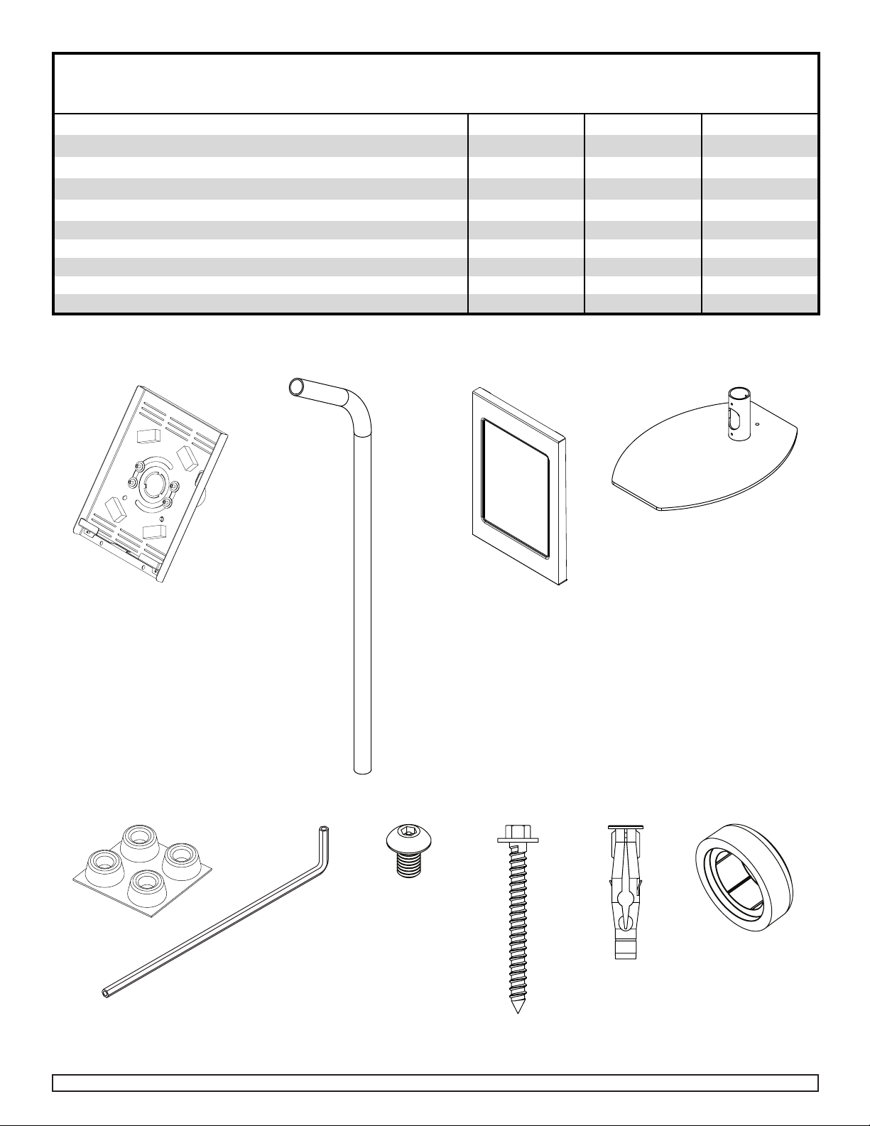
PARTS LIST
Description Qty. PTS510I PTS510I-W
rotation plate 1 145-T1750 145-2750 145-4750
A
stand tube 1 145-T1738 145-2738 145-4738
B
cover plate 1 145-T1748 145-2748 145-4748
C
base weldment 1 145-T1735 145-2735 145-4735
D
rubber feet 1 570-1036 570-1036 570-1036
E
5/32'' (4mm) allen wrench 1
F
M5 x 10mm socket pin screw 6
G
floor screw 1
H
concrete anchor 1
I
screw cover 1 560-1029 560-2029
J
A
B
C
560-9646 560-9646 560-9646
520-1164 520-2031 520-2031
5S1-015-C03 5S1-015-C04 5S1-015-C04
590-0320 590-0320 590-0320
D
PTS510I-S
560-2029
E
F G
2 of 6
H
I
ISSUED: 01-29-13 SHEET #:125-9353-1 02-23-13
J
Page 3

Attach rubber feet (E) to base plate (D) as shown.
1
D
E
E
APPROXIMATE SPACING
Place stand tube (B) on base plate (D).
2 3
B
D
Secure assembly using
two M5 x 8 mm socket pin
screws (G).
B
G
3 of 6
ISSUED: 01-29-13 SHEET #:125-9353-1 02-23-13
Page 4

Place rotation plate (A) onto stand tube (B) and secure using two M5 x 8mm socket pin screws (G).
4
A
Insert iPad™ into rotation plate (A) and
5
run the USB cable through the stand
tube (B) and out the cable management
position.
B
A
G
CABLE
MANAGEMENT
B
4 of 6
ISSUED: 01-29-13 SHEET #:125-9353-1 02-23-13
Page 5

90
Hook cover plate (C) into adapter plate (A) and secure using two M5 x 8mm socket pin screws (G).
6
C
G
A
Alternate between landscape and portrait
7
view by pulling out the release pin and
simultaneously turning the display.
A
PULL PIN TO ROTATE IPAD 90°
5 of 6
ISSUED: 01-29-13 SHEET #:125-9353-1 02-23-13
Page 6

WARNING
• Do not drill into mortar joints! Be sure to mount in a solid part of the cement or tile ooring. Material must meet
ASTM C-90 specications. It is suggested that a standard electric drill on slow setting is used to drill the hole
instead of a hammer drill.
• Concrete must be 2000 psi density minimum. Lighter density concrete may not hold concrete anchor.
Position mount assembly in desired
8
location. Use base plate (D) as a
template to mark holes. Drill one hole
using 5/16’’ (8 mm) drill bit to a minimum
depth of 2.5" (64mm). Concrete must be
at least 2000 psi density. Insert anchor
(I) in hole ush with the oor as shown
in gure 1a. Place mount assembly over
anchor and secure with one #14 wood
screw (H) as shown in gure 2a. Tighten
fastener. Place one plastic hex screw
cover (J) over #14 screw (H).
2.5”
432
H
D
I
concrete
surface
WARNING
•
attached, but do not overtighten. Overtightening
can damage screws, greatly reducing their holding
power.
• Never tighten in excess of 80 in • lb (9 N.M.).
WARNING
• Always attach concrete expansion anchors directly
to load-bearing concrete.
• Never attach concrete expansion anchors to
concrete covered with tile, carpeting, hardwood
thicker than 5/8", custom fasteners must be
supplied by installer (not UL evaluated).
6 of 6
J
H
ISSUED: 01-29-13 SHEET #:125-9353-1 02-23-13
 Loading...