How it Works
Log In / Sign Up
Buy Points
How it Works
FAQ
Contact Us
Questions and Suggestions
Users
Peerless Industries
Loading...
P
PRS45
3
PRS-EXA-S-W
PRS-EXA-W
2
PRS-EXB
2
PRS-EXB-S
2
PRS-EXB-S-W
PRS-EXB-W
2
PRS-EXC
3
PRS-EXC-S
4
PRS-EXC-S-W
PRS-EXC-W
6
PRS-KIT0811
2
PRS-KIT1420
2
PRS-KIT2026
2
PRSS-455
4
PRSS-ALU0811
PRSS-UNV-W
2
PRS-UNV
PRS-UNVP
2
PRS-UNVP-S
2
PRS-UNVP-W
2
PRS-UNV-S
4
PRS-UNV-W
2
PS-1
PS-2
2
PS200
2
PSC-03
PSC-04
PSC-05
PSC-06
PSC II Series
PSM-UNV-W
2
PSMU-PRS
2
PSMU-PRS-S
3
PSMU-PRSS-S
2
PSP2-W
PSP5
PSP5-W
2
PSTA-028-W
PSTA-600
2
PSTK-028
PSTK-028-W
3
PSTK-2955-W
2
PSTK-600
2
PT-120
PT-30
PT-40
PT-50
PT-60
PT630
5
PT632
PT640
6
PT650
4
PT660
5
PT-80
PTL635
PTL650
PTLP650
PTM200
PTM200-S
2
PTM400
PTM400-W
PTS510I
2
PTS510I-W
3
PTT188763
PTT188763-LHD
PTT188773
PTT188773-LHD
PTT188780 Series
PTT188790 Series
PUREFIRE PF-1000
PureFire PF-110
PureFire PF-140
PureFirePF-1500
PureFire PF-210
PureFire PF-399
PureFire PF-50
PureFire PF-80
PUREFIRE PF-850
PUREFIRE PFC-1000
PUREFIRE PFC-1500
PUREFIRE PFC-850
PUREFIRE PFW-200
PUREFIRE PFW-399
PWA-14W
2
PWMT300
PWS211
PWS320-BK
PWS421
PWV210-BK
PWV240-BK
PWV250-BK
Q
Q-21-20
Q-ACC-FS14
Q-ACC-QF2-2
Q-ACC-QF2-4
Q-ACC-QFD2-3
R
RMI1
RMI2C
2
RMI2W
2
Loading...
Loading...
Nothing found
PT630
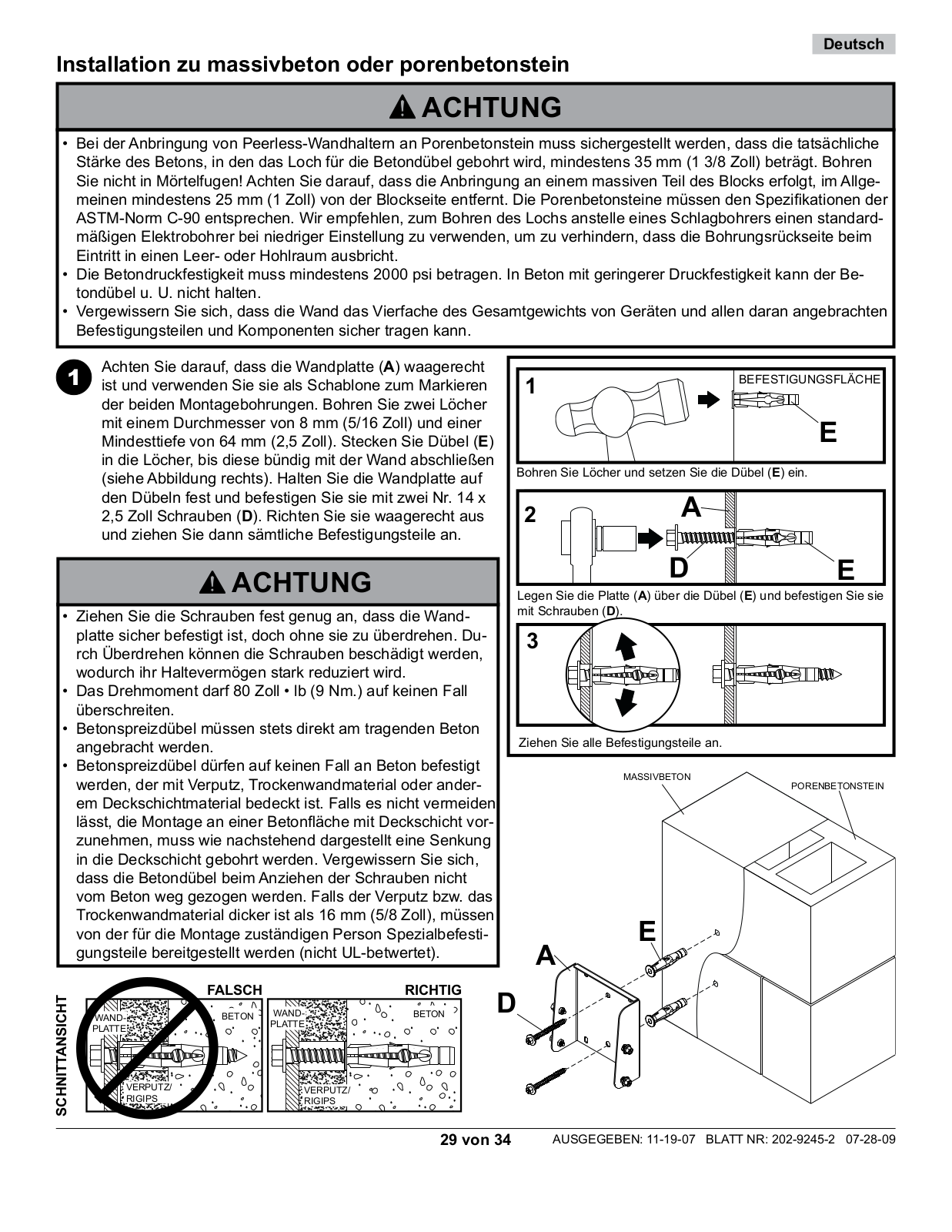
Installation
8 pgs
307.25 Kb
0
Sell Sheet
2 pgs
218.59 Kb
0
Specsheet
2 pgs
282.53 Kb
0
User Manual
34 pgs
5.69 Mb
0
User Manual
20 pgs
743.82 Kb
0
Table of contents
Loading...
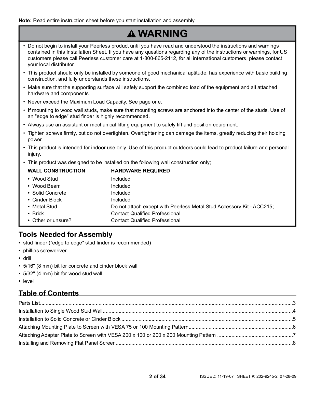
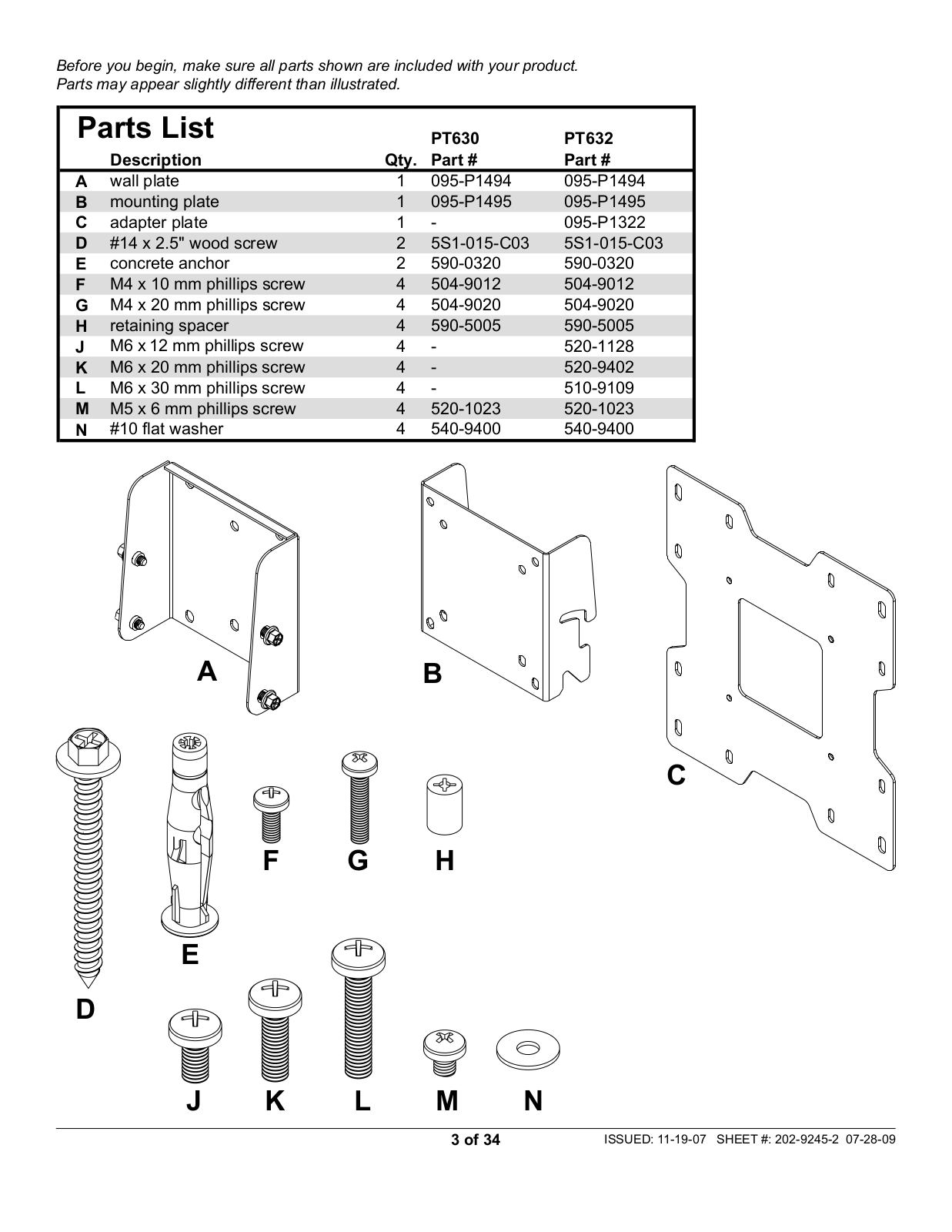
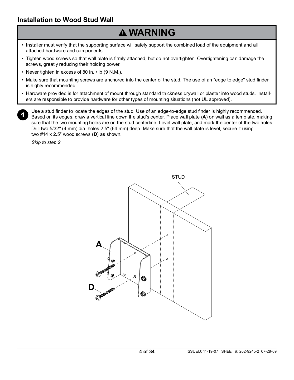
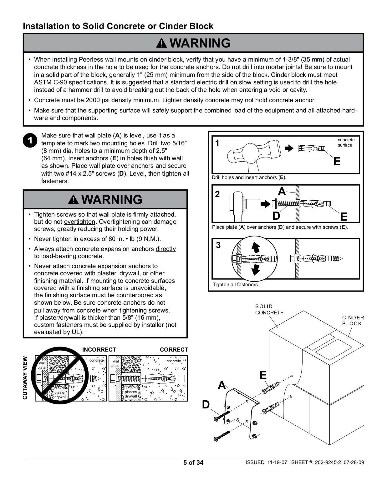
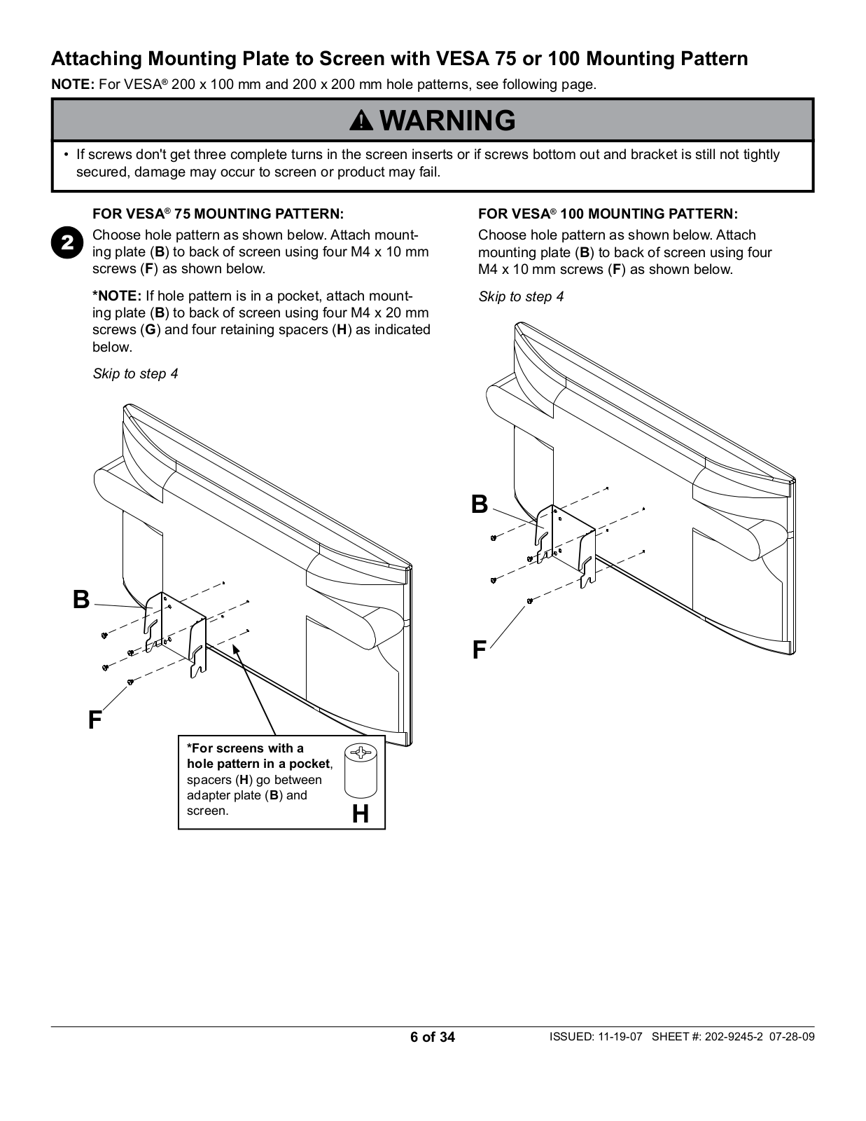
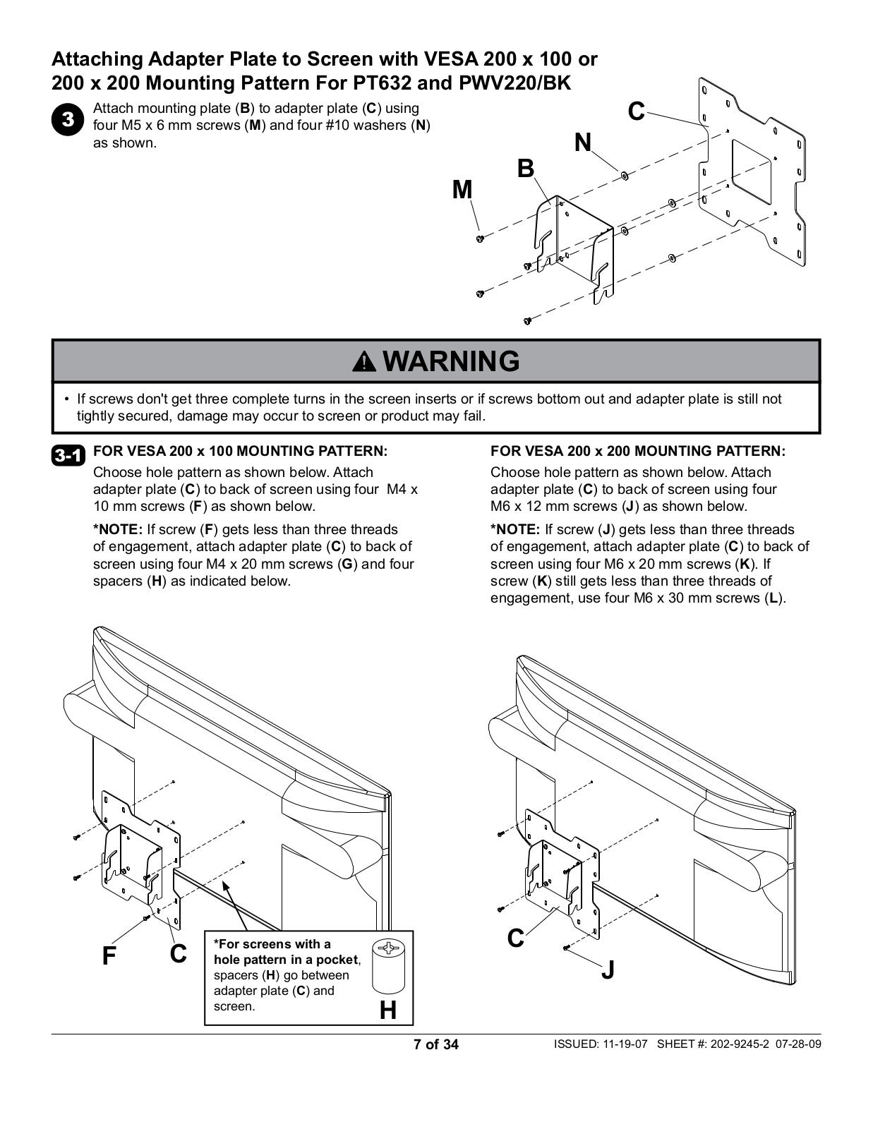
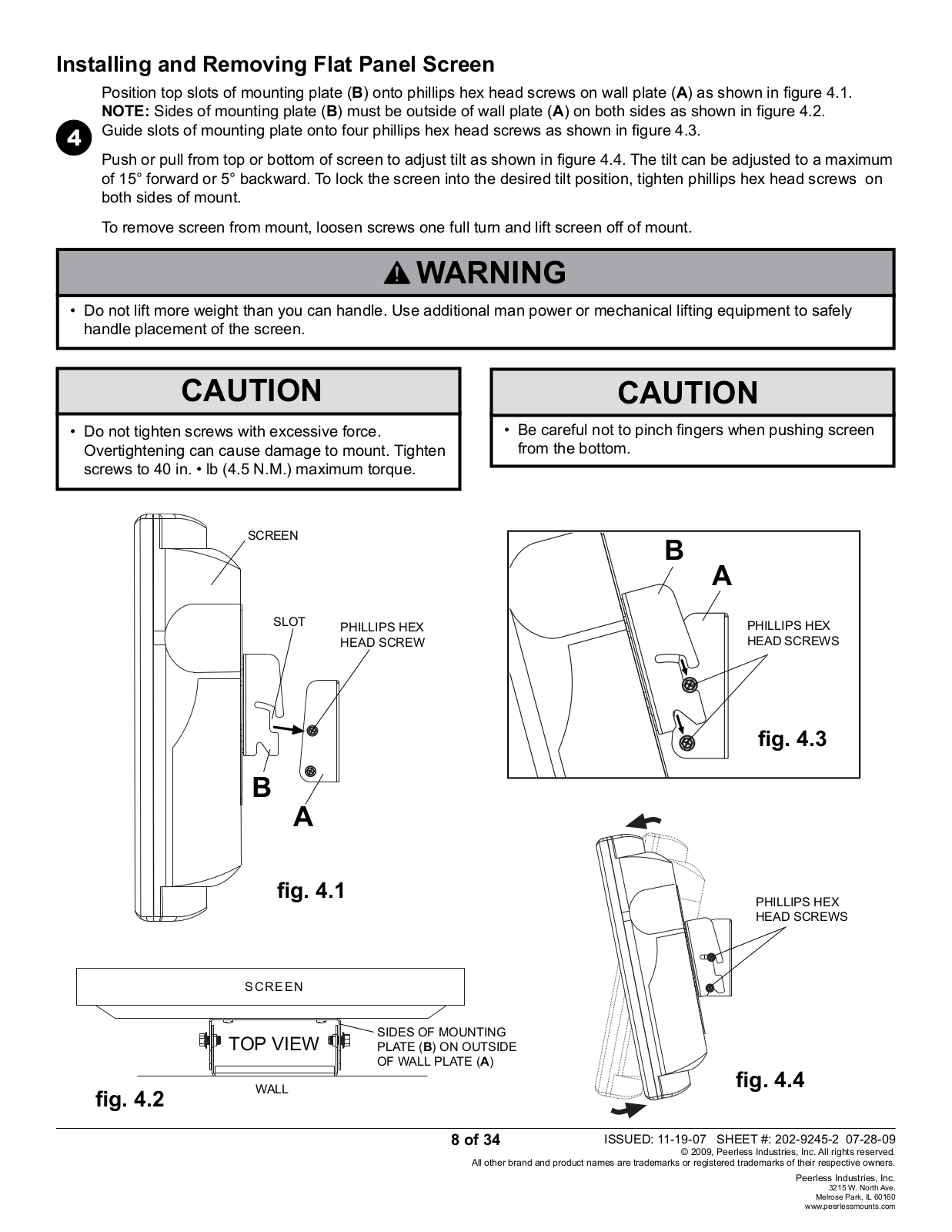
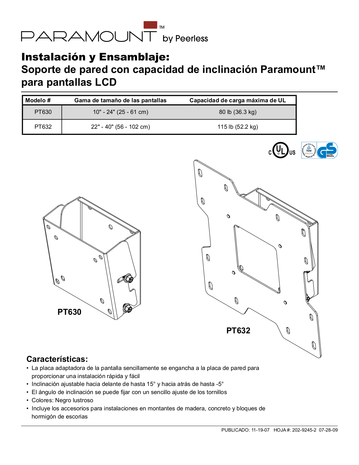
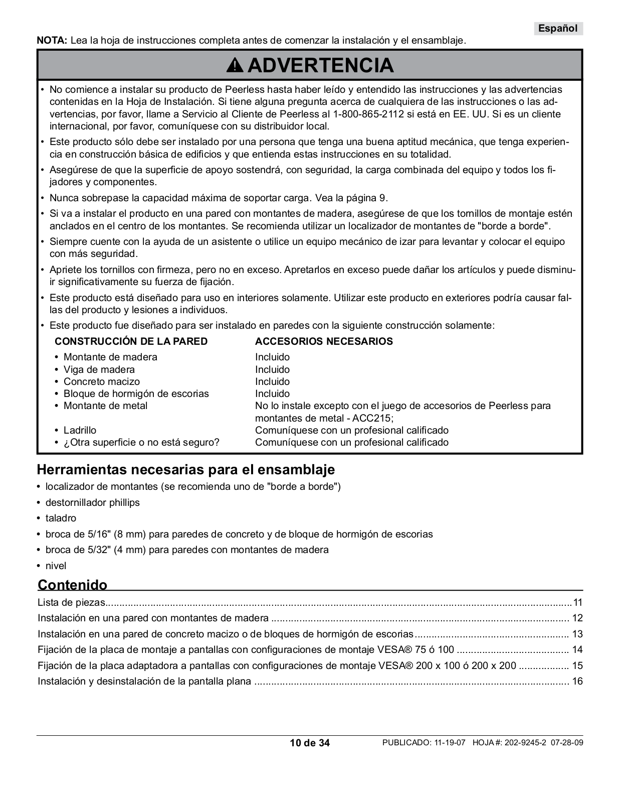
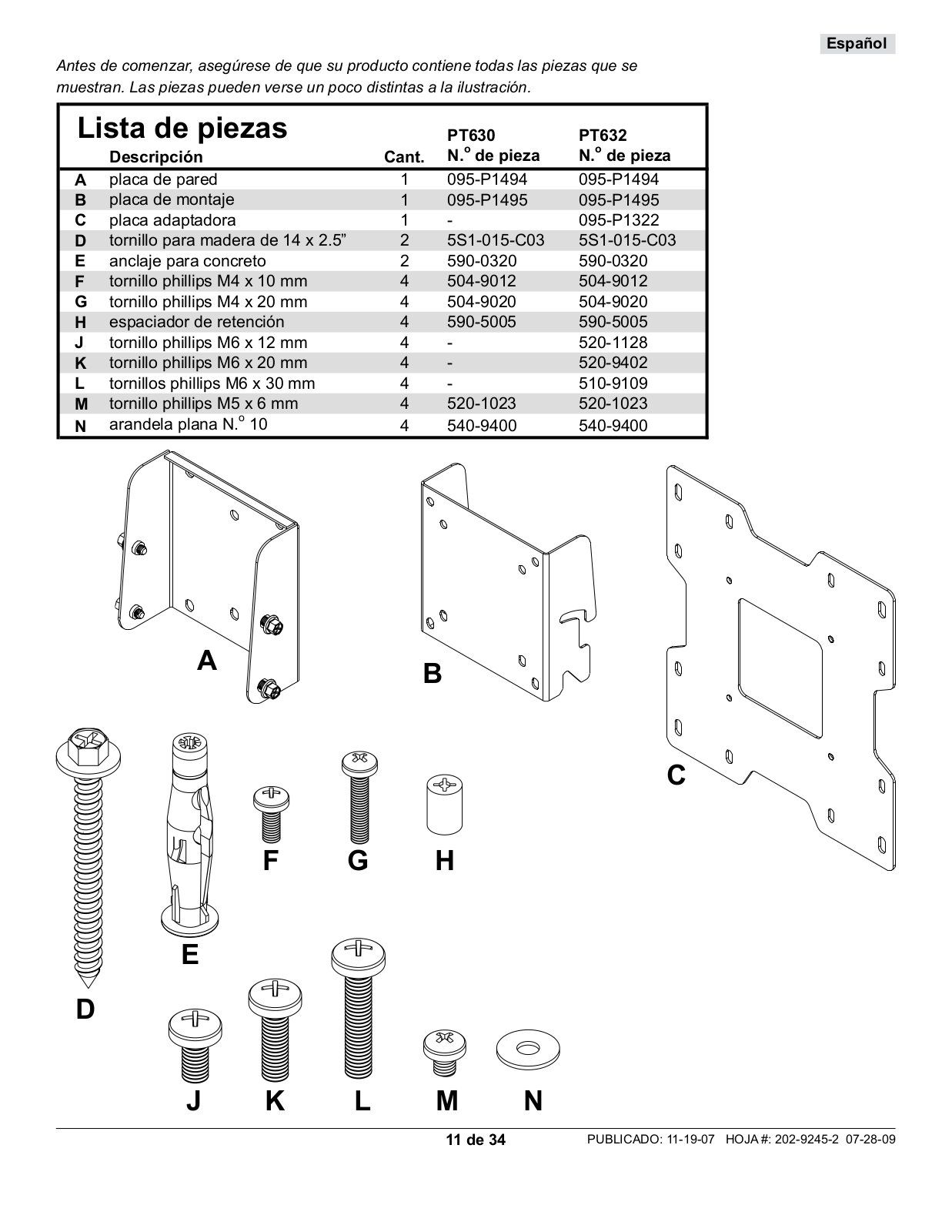
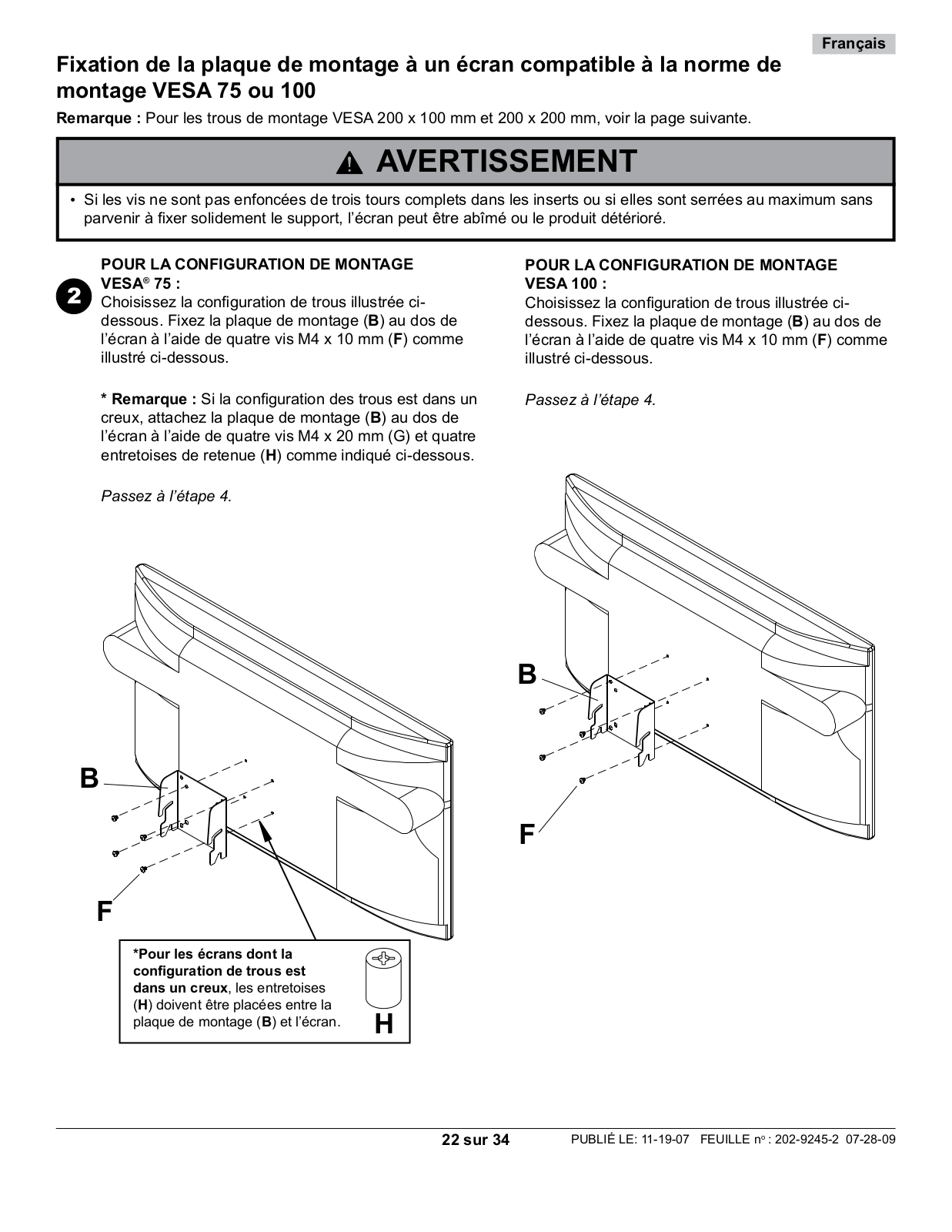
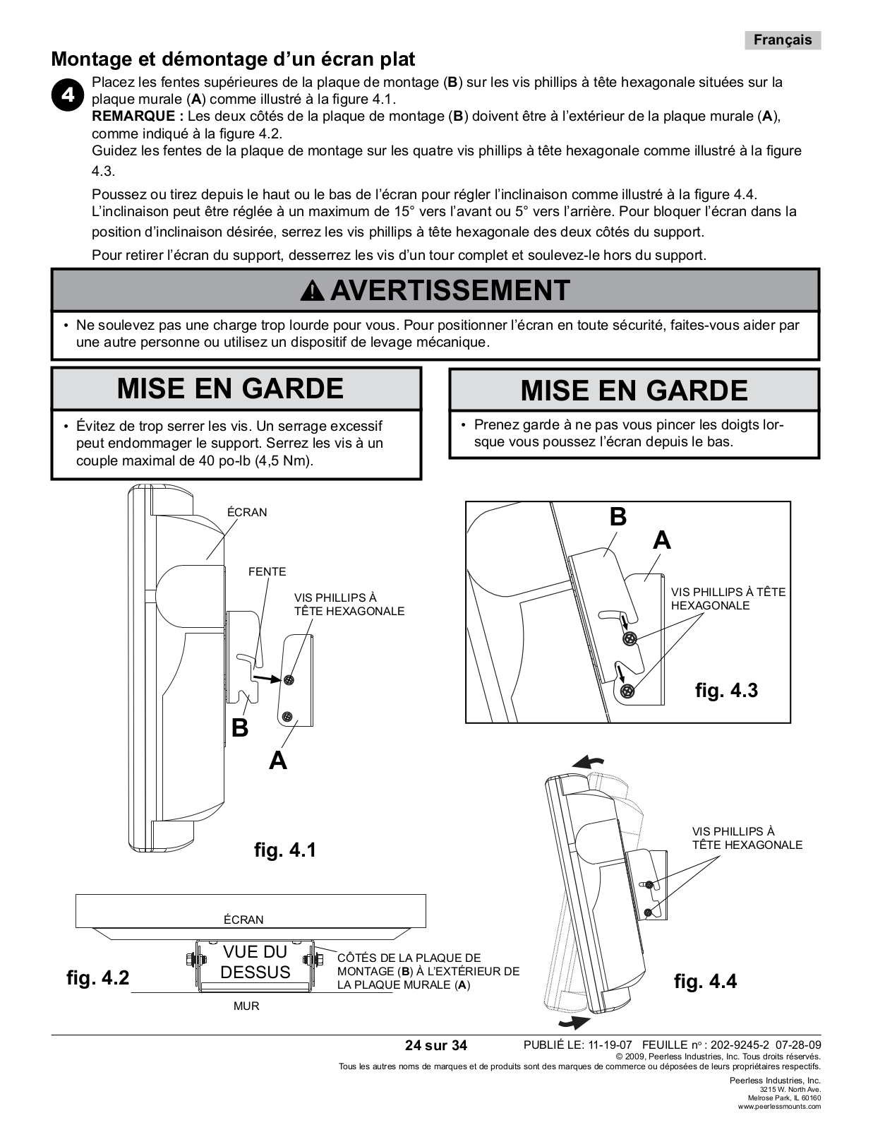
Peerless Industries PT632, PT630 User Manual
...
Peerless Industries User Manual
Download
Specifications and Main Features
Frequently Asked Questions
User Manual
Download
Loading...
+
hidden pages
Unhide
You need points to download manuals.
1 point = 1 manual.
You can buy points or you can get point for every manual you upload.
Buy points
Upload your manuals