

PEERLESS PT-30, PT-40, PT-60, PT-80, PT-50 Installation, Operation & Maintenance Manual
...Page 1
Partner
®
Water Heater
PT-30 PT-40 PT-50 PT-60 PT-80 PT-120
Peerless
®
Indirect-Fired
Installation,
Operation &
Maintenance
Manual
Page 2

USING THIS MANUAL 1
A. INSTALLATION SEQUENCE . . . . . . . . . . . . . .1
B. SPECIAL ATTENTION BOXES . . . . . . . . . . . . .1
PRODUCT & SAFETY INFORMATION 2
1. PREINSTALLATION 3
A. CODES COMPLIANCE . . . . . . . . . . . . . . . . . . .3
B. CODES RESTRICTIONS . . . . . . . . . . . . . . . . . .3
C. OPERATING RESTRICTIONS . . . . . . . . . . . . . .3
D. LOCATING WATER HEATER . . . . . . . . . . . . . .3
E. PRODUCT SELECTION . . . . . . . . . . . . . . . . . .4
F. RECOMMENDED CLEARANCES . . . . . . . . . . .5
2. INSTALLATION - PIPING 6
A. TEMPERATURE & PRESSURE (T&P)
RELIEF VALVE . . . . . . . . . . . . . . . . . . . . . . . . .6
B. DRAIN VALVE . . . . . . . . . . . . . . . . . . . . . . . . . .6
C. AUTOMATIC AIR VENT . . . . . . . . . . . . . . . . . .7
D. THERMAL EXPANSION . . . . . . . . . . . . . . . . .7
E. WATER HAMMER . . . . . . . . . . . . . . . . . . . . . .7
F. VACUUM BREAKER . . . . . . . . . . . . . . . . . . . . .7
G. GENERAL PIPING . . . . . . . . . . . . . . . . . . . . . . .7
H. DOMESTIC PIPING . . . . . . . . . . . . . . . . . . . . . .7
I. THERMOSTATIC MIXING VALVE . . . . . . . . . .8
J. RECIRCULATION PIPING . . . . . . . . . . . . . . . . .8
K. MULTIPLE WATER HEATER SYSTEMS . . . . .8
L. BOILER PIPING . . . . . . . . . . . . . . . . . . . . . . . . .8
3. INSTALLATION - PIPING DRAWINGS 9
4. INSTALLATION - WIRING 16
A. WIRING REQUIREMENTS . . . . . . . . . . . . . . .16
B. CIRCULATORS . . . . . . . . . . . . . . . . . . . . . . . .16
C. ZONE VALVES . . . . . . . . . . . . . . . . . . . . . . . .16
D. SNAPSET CONNECTION . . . . . . . . . . . . . . . .16
5. INSTALLATION - WIRING DRAWINGS 17
6. WATER HEATER START-UP 22
A. FILLING THE INNER (DOMESTIC WATER)
TANK . . . . . . . . . . . . . . . . . . . . . . . . . . . . . . .22
B. FILLING THE OUTER (BOILER WATER)
TANK . . . . . . . . . . . . . . . . . . . . . . . . . . . . . . .22
C. GENERAL NOTES . . . . . . . . . . . . . . . . . . . . .23
D. ADJUSTING THE WATER HEATER
THERMOSTAT . . . . . . . . . . . . . . . . . . . . . . . .23
7. WATER HEATER MAINTENANCE 24
A. MAINTENANCE SCHEDULE . . . . . . . . . . . . .24
B. FILLING WATER HEATER . . . . . . . . . . . . . . .24
C. DRAINING WATER HEATER . . . . . . . . . . . . .24
D. DRAINING INNER (DOMESTIC WATER)
TANK . . . . . . . . . . . . . . . . . . . . . . . . . . . . . . .25
E. DRAINING OUTER (BOILER WATER)
TANK . . . . . . . . . . . . . . . . . . . . . . . . . . . . . . .25
8. TROUBLESHOOTING 26
9. REPAIR PARTS 27
10. WATER HEATER DIMENSIONS &
RATINGS 29
11. PERFORMANCE RATINGS 30
TABLE OF CONTENTS
TABLE OF CONTENTS
Page 3
A. INSTALLATION SEQUENCE
Follow the installation instructions provided in this manual
in the order shown. The order of these instructions has
been set in order to provide the installer with a logical
sequence of steps that will minimize potential
interferences and maximize safety during boiler
installation.
B. SPECIAL ATTENTION BOXES
Throughout this manual special attention boxes are
provided to supplement the instructions and make special
notice of potential hazards. The definition of each of
these categories, in the judgement of PB Heat, LLC
are as follows:
USING THIS MANUAL
Indicates special attention is needed, but not directly
related to potential personal injury or property
damage.
NOTICE
Indicates a condition or hazard which will or can
cause minor personal injury or property damage.
CAUTION
DANGER
Indicates a condition or hazard which will cause
severe personal injury, death or major property
damage.
Indicates a condition or hazard which may cause
severe personal injury, death or major property
damage.
WARNING
1
USING THIS MANUAL
Page 4
2
PRODUCT SAFETY & INFORMATION
PRODUCT SAFETY & INFORMATION
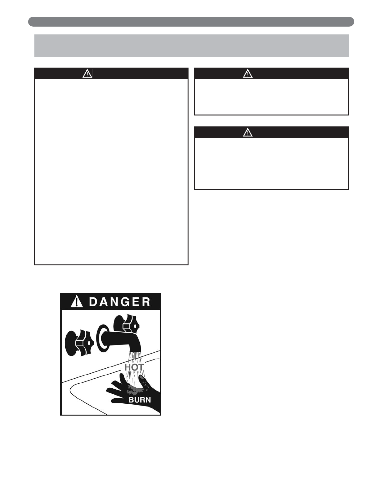
DANGER
HOT WATER CAN SCALD!
• Water temperatures over 125ºF can cause severe
burns instantly or death from scalding.
• Children, disabled and elderly are at highest risk of
being scalded.
• Never leave them unattended in or near shower,
bathtub or sink.
• Never allow small children to use a hot water faucet
or draw their own bath.
• If anyone using hot water in the building fits the
above description or if local codes or state laws
require specific water temperatures at hot water
faucet, it is recommended:
– to install a thermostatic mixing valve at this
appliance or at each water faucet.
or
– to set the thermostat knob for the lowest
temperature which satisfies your hot water
needs.
• Water drained from the system drain valves may be
extremely hot. To avoid injury:
– Make sure all connections are tight.
– Direct water flow away from any person.
Protection must be taken against excessive
temperature and pressure!
• Installation of a Temperature & Pressure (T&P) relief
valve is required.
WARNING
To prevent damage to the inner tank, the installer
must:
• Always fill inner tank prior to outer tank and always
drain outer tank prior to inner tank.
• Relieve primary system pressure below 15 psig
prior to draining inner tank.
CAUTION
Page 5

3
1. PREINSTALLATION
A. CODES COMPLIANCE
Water heater installation must conform with the
instructions in this manual and where applicable:
• local, state, provincial, and national codes, laws,
regulations and ordinances.
• in Canada - CAN / CGA B149.1 or B149.2
Installation Code.
Peerless
®
Partner®water heaters are exempt from ASME
Section VIII, Division 1 Code construction per
Interpretation VIII-86-136. Check with local codes for
applicability.
Where recommendations in this manual differ from local,
or national codes, the local or national codes take
precedence.
B. CODES RESTRICTIONS
1. Single wall heat exchanger in the Peerless®Partner
®
water heater complies with National Standard
Plumbing Code, provided that:
a. boiler water (including additives) is practically
non-toxic, having toxicity rating or class of 1, as
listed in Clinical Toxicology of Commercial
Products, and
b. boiler water pressure is limited to maximum 30
psig by approved relief valve.
2. Single wall heat exchangers are permitted under the
Uniform Plumbing code - Paragraph L3.2. and L3.3 if
they satisfy all of the following requirements.
a. The heat transfer medium is potable water or
contains only substances which are recognized as
safe by the U.S. Food and Drug Administration.
b. The pressure of the heat transfer medium is
maintained less than the normal minimum
operating pressure of the potable water system
Exception: Steam complying with section
#1 above.
c. The equipment is permanently labeled to indicate
that only additives recognized as safe by the FDA
shall be used in the heat transfer medium.
Other heat exchanger designs may be permitted
where approved by the Administrative Authority.
C. OPERATING RESTRICTIONS
1. Maximum domestic hot water temperature is 194ºF
for commercial applications and 140ºF for residential
applications.
2. Maximum boiler water temperature is 210ºF.
3. Maximum working pressure for inner (domestic water)
tank is 150 psig.
4. Maximum working pressure for outer (boiler water)
tank is 45 psig.
5. pH and chloride limits for water heaters are:
a. chloride, less than 150 mg/l (ppm)
b. pH value min. 6 - max. 8
D. LOCATING WATER HEATER
1. This water heater is not intended for outdoor
installations.
2. Keep distance between boiler and water heater to a
minimum to:
a. reduce piping heat loss
b. provide minimal friction loss
3. Locate water heater so that any leakage from the tank
or water connections will not cause damage to the
area adjoining the water heater or to lower floors in
the structure.
When such a location is unavoidable, a suitable
drain pan with adequate drainage, should be
placed under the water heater.
4. The Peerless
®
Partner®water heaters are designed for
vertical installation only.
Peerless®Partner®water heaters will absorb less than
200,000 BTU/hr when domestic water outlet
temperature is 210°F and boiler water supply
temperature is 240°F. Listed outputs are based on
ASME Section VIII Interpretation VIII-1-86-136.
NOTICE
Do not install the water heater on any application if
the boiler piping contains non-oxygen barrier tubing
or if the boiler piping is considered an “open
system”. Exposing the outer tank of the water heater
to oxygen contamination will lead to premature tank
failure and denial of the warranty.
NOTICE
Any water conditioning system must be installed
and maintained in accordance with manufacturer’s
specifications.
NOTICE
PREINSTALLATION
Page 6

4
E. PRODUCT SELECTION
1. The following guidelines apply to residential systems
only. For commercial or institutional installations
contact your local PB Heat, LLC representative.
2. Determine the quantity of domestic hot water
required. Factors to consider:
a. Estimate typical peak hour demand. Determine
the general time of day (morning, noon, evening)
when the most hot water is used. Use chart below
to determine potential maximum usage.
b. Estimate unusual peak draw demand.
Whirlpool baths, hot tubs, and multiple head
showers require large quantities of hot water in a
short period of time. Contact fixture manufacturer
for quantity of water required. Generally speaking,
these circumstances can only be met with larger
storage volumes.
c. Domestic Water Temperature. Most residential
usage will be satisfied with 119°F water, the
temperature setting recommended by the
Consumer Product Safety Commission. Some
applications such as laundry and dishwashers may
require a higher temperature.
Ratings can be improved by increasing Peerless
®
Partner®thermostat setting and using a mixing
valve to temper the hot water to the proper
temperature. When temperatures greater than
119°F are required, use a mixing valve at the
outlet of the water heater or anti-scald fittings at
point of use.
d. Domestic water priority. First hour ratings may
be less than published when boiler output is
shared with space heating. Generally a consumer
will notice a drop in domestic water temperature
before a drop in space heating temperature.
Giving domestic water production priority by
directing entire boiler output to Peerless
®
Partner
®
will maximize domestic water output. However,
prioritization controls could result in an
unacceptable drop in space heating temperature
when large quantities of domestic hot water are
used, and a prioritization control malfunction
could result in loss of space heating.
3. Multiple Water Heaters. Peak domestic water
usage (first hour rating) or unusual peak draw may
not be met with a single water heater. Multiple units
can be installed as either a bank of tanks acting as a
single unit, or as multiple individual units sized and
located for specific draw situations.
PREINSTALLATION
Estimate of Peak Domestic Hot Water Usage
Average Gallons of Times Used During Gallons Used in
Use Hot Water per Usage One Hour One Hour
Shower 20 x _____________ = _____________
Bath 20 x _____________ = _____________
Shaving 2 x _____________ = _____________
Hands and Face Washing 4 x_____________ = _____________
Hair Shampoo 4 x_____________ = _____________
Hand Dish Washing 4 x _____________ = _____________
Automatic Dish Washing 14 x _____________ = _____________
Food Preparation 5 x_____________ = _____________
Wringer Clothes Washer 26 x _____________ = _____________
Automatic Clothes Washer 32 x _____________ =
Total Peak Hour Demand = __________
The Peerless®Partner®indirect-fired water heater is
deemed to be used in a "commercial setting" if at
any time the unit is operated at a temperature over
150°F. Refer to warranty for additional information.
NOTICE
DANGER
Water temperatures over 125°F
can cause severe burns instantly,
or death from scalds.
Children, disabled, and elderly are
at the highest risk of being
scalded.
See instruction manual before
setting temperature at water
heater.
Feel water before bathing or showering.
Temperature limiting valves are available, see
manual.
Page 7
5
PREINSTALLATION
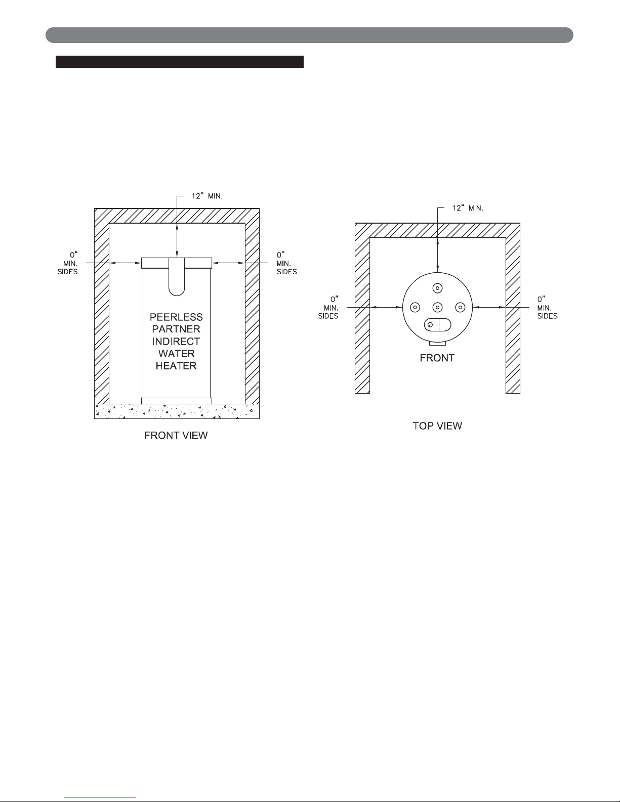
F. RECOMMENDED CLEARANCES
1. Water heater should be installed to allow adequate
clearance for servicing.
2. Zero clearance is permissible to any side of the
Peerless
®
Partner®water heater, but information labels
may be hidden.
3. Recommended top or vertical clearance is 12"
minimum.
4. Refer to boiler manual for boiler clearances.
5. See Figure 1.1 for recommended service clearances.
Figure 1.1: Recommended Clearances
Page 8
6
2. INSTALLATION – PIPING
A. TEMPERATURE & PRESSURE (T&P)
RELIEF VALVE
1 Every Peerless®Partner®water heater must be
protected with a T&P relief valve.
2 Determine T&P relief valve size by the following
specifications, unless they conflict with local codes:
a. Peerless
®
Partner®30/40/50: 3/4" NPT with an
AGA Rating of 100,000 BTU/hr and a maximum
pressure rating of 150 psig. (Watts 100XL-8 or
equivalent).
b. Peerless
®
Partner®60/80/100/120: 3/4" NPT with
an AGA Rating of 200,000 BTU/hr and a
maximum pressure rating of 150 psig. (Watts
40XL-8 or equivalent).
3. Standard Installation:
Install T&P relief valve in the Auxiliary connection
located behind the air vent on the top of the water
heater (Figure 3.1).
or
Install the T&P relief valve in the run (straight through
leg) of a tee located at the domestic hot water outlet
when using the Auxiliary connection for a
recirculation return (Figure 3.2).
4. Commonwealth of Massachusetts Installation:
Follow this procedure for jurisdictions requiring a
vacuum breaker to be installed on the domestic cold
water inlet.
• Install the T&P in the run (straight through leg) of
tee located at the domestic hot water outlet. Use a
long element T&P relief valve (Fig. 3.4).
5. T&P Relief Valve Discharge Piping:
T&P relief valve discharge piping must be:
• made of material serviceable for temperatures of
250ºF or greater.
• directed so that hot water flows away from all
persons.
• directed to a suitable place for disposal.
• installed so as to allow complete draining of the
T&P relief valve and discharge line.
T&P relief valve discharge piping must not be:
• excessively long. Using more than 2 elbows or 15
feet of piping can reduce discharge capacity.
• directly connected to a drain. Terminate the
discharge piping within 6" from a drain and within
6" of the floor. Refer to local codes.
• plugged, reduced or restricted.
• subject to freezing.
B. DRAIN VALVE
Drain valve and fittings are supplied by others.
1. Standard Installation
a. Install a tee connection at the domestic cold water
inlet (Fig. 3.1 and 3.2).
b. Pipe the drain piping with drain valve from the tee
connection to:
i. a suitable place for disposal
or
ii. terminate within 12" of the floor
2. Commonwealth of Massachusetts Installation
a. Use the drain tube assembly supplied in the tank
carton.
b. Thread a 3/4" close nipple onto the Auxiliary
connection and insert an open-end dip tube into
the Auxiliary connection on top of water heater.
As shown in Fig. 3.3.
c. Install a 3/4" NPT elbow to the Auxiliary
connection, see Fig. 3.4.
d. Pipe the drain piping with drain valve from the
elbow connection to:
To reduce risk of excessive pressures and
temperatures in the water heater, install temperature
and pressure protective equipment required by local
codes, but no less than a combination temperature
and pressure relief valve certified by a nationally
recognized testing laboratory that maintains periodic
inspection of production of listed equipment or
materials, as meeting the requirements for Relief
Valves and Automatic Gas Shutoff Devices for Hot
Water Supply Systems, ANSI Z21.22. This valve must
be marked with a maximum working pressure of the
water heater.
CAUTION
For proper operation of the T&P and to prevent the
T&P from activating due to boiler water temperature,
use a T&P relief valve with extended element.
Recommended, an 8" minimum length.
NOTICE
Do not install any valve between T&P relief valve and
tank connection or on T&P relief valve discharge
piping. Do not plug T&P relief valve or discharge
piping. Improper placement and piping of T&P relief
valve can cause severe personal injury, death or
substantial property damage.
WARNING
INSTALLATION - PIPING
Page 9
7
i. a suitable place for disposal
or
ii. terminate within 12" of the floor
C. AUTOMATIC AIR VENT
1. Remove plastic shipping cap from 1/2" NPT pipe
fitting on top center of water heater.
2. Install 1/2" x 1/8" reducer bushing provided with water
heater, using suitable pipe dope or tape.
3. Install automatic air vent provided with water heater,
using suitable pipe dope or tape.
4. Unscrew vent cap on air vent one full turn. Leave cap
unscrewed one turn for normal venting.
D. THERMAL EXPANSION
If a backflow preventer, check valve or pressure reducing
valve is piped on cold water supply piping of water
heater, install an expansion tank on cold water supply line
to prevent normal thermal expansion from repeatedly
forcing open T&P relief valve.
E. WATER HAMMER
Dishwashers, clothes washers and fast-closing positive
shut-off valves incorporated in the system all contribute to
creating water shock. Install a water hammer arrester to
prevent damage to pipes and appliances. See device
manufacturer’s instructions for application and
installation.
F. VACUUM BREAKER
Installing a vacuum breaker Watts N36-M1 or equivalent
on the domestic cold water inlet will prevent damage to
the inner tank if a negative pressure is developed in the
domestic supply line. See manufacturer’s instructions for
application and installation of the vacuum breaker.
G. GENERAL PIPING
1. For domestic water piping diagrams, see Figures 3.1
through 3.4.
2. See Figures 3.5 through 3.9 for boiler water piping
3. See Figures 3.10 and 3.11 for multiple water heater
domestic piping.
4. See Figure 3.12 for multiple water heater boiler
piping.
5. See Table 1.1 for domestic and boiler piping
connection sizes.
6. All plumbing must meet or exceed all local, state and
national plumbing codes.
7. Use pipe dope or tape suitable for potable water
systems.
8. Use isolation valves to isolate system components.
H. DOMESTIC PIPING
1. Union on domestic hot water outlet should be piped
at a higher elevation than domestic water drain valve.
This will make draining the water heater easier.
2. Install unions for easy removal of water heater. Use
dielectric unions or couplings to protect hot and cold
water fittings from corrosion when connecting
dissimilar materials such as copper and galvanized
iron pipe.
3. If copper pipe is used for domestic water connections,
first solder pipe to a threaded adapter and then screw
adapter into cold water inlet on top of water heater.
Inlet contains an internal plastic dip tube which can
be damaged by heat from soldering.
Water hammering within the domestic piping system
can cause premature failure of the inner tank of the
water heater. This type of failure is NOT covered
under warranty.
NOTICE
T&P relief valve is not intended for constant duty,
such as relief of pressure due to repeated normal
system expansion. Correct this condition by installing
a properly sized expansion tank in domestic water
system. Refer to expansion tank manufacturer’s
installation instructions for proper sizing.
CAUTION
Table 1.1:
Water
Heater
Model
Number
Connections - NPT Recirculation Dip Tube Draining Dip Tube
Recommended
Minimum
Boiler Piping
Domestic
Water
Inlet/Outlet
Boiler Water
Supply/
Return
Auxiliary
Connection
Length
(inches)
Diameter
(inches)
Length
(inches)
Diameter
(inches)
Diameter
(inches)
PT-30 3/4 1 3/4 34 3/4 34 3/4 1
PT-40 3/4 1 3/4 43 3/4 43 3/4 1
PT-50 3/4 1-1/4 3/4 25 3/4 52 3/4 1-1/4
PT-60 3/4 1-1/4 3/4 34 3/4 62 3/4 1-1/4
PT-80 1-1/2 1-1/2 1-1/2 25 1-1/2 48 1-1/2 1-1/2
PP-120 1-1/2 2 1-1/2 32 1-1/2 61 1-1/2 2
INSTALLATION - PIPING
Page 10
8
4. When the water supply pressure is higher than 70
psig, it is recommended to install a pressure reducing
valve on cold water supply line to prevent water loss
through T&P relief valve.
5. If water heater will replace tankless coil in boiler,
disconnect piping to coil. Allow water to drain from
coil. Do not plug tankless coil.
I. THERMOSTATIC MIXING VALVE
1. It is recommended to install an optional mixing valve
on the domestic hot water outlet.
2. Mixing valve should comply with ASSE 1017.
J. RECIRCULATION PIPING
1. T&P relief valve must be installed in run (straight
through leg) of tee located at domestic hot water
outlet of water heater.
2. It is recommended that the recirculation dip tube be
installed in auxiliary connection using a close nipple
assembly as shown Fig. 3.3, page 9. See Table 1.1
page 6 for diameter and length of dip tube.
3. A stainless steel or bronze circulator is recommended.
4. Install automatic mixing valve either at the hot water
outlet of water heater or each hot water faucet.
K. MULTIPLE WATER HEATER SYSTEMS
1. Parallel Pipe Recirculation Systems - Manifold
recirculation return to all water heaters.
2. Series Piped Systems - Piped return to the leading
(cold water inlet) water heater.
3. Install automatic mixing valve either at the hot water
outlet of water heater or each hot water faucet.
L. BOILER PIPING
1. If plastic pipe is used for boiler water piping, it must
have a maximum oxygen diffusion rate of 0.1
mg/liter-day for boiler and water heater protection.
2. Boiler water (including additives) must be practically
non-toxic, having toxicity rating or class of 1, as listed
in Clinical Toxicology of Commercial Products.
If antifreeze is used in boiler system, local codes may
require a backflow preventer on cold water supply
line. Use antifreeze specifically intended for hydronic
heating systems. Inhibited propylene glycol is
recommended at a maximum 50/50 mixture.
WARNING
Do not use automotive, ethylene glycol or petroleumbased antifreeze. Do not use any undiluted
antifreeze. This can cause severe personal injury,
death or substantial property damage.
DANGER
Plugging tankless coil inlet and outlet will result in
severe personal injury, death, or substantial property
damage.
Do not apply heat to the cold water inlet when
making sweat connections to water heater. Sweat
tubing to adapter before fitting adapter to cold water
inlet of heater. It is imperative that no heat be applied
to the cold water inlet, as it contains a non metallic
dip tube.
NOTICE
The Peerless®Partner®IDWH must be installed on a
closed type hydronic system. Failure to provide such
a system will result in premature failure of the outer
tank and annulment of warranty.
NOTICE
DANGER
Failure to install automatic mixing valve where
recommended will result in severe personal injury or
death.
INSTALLATION - PIPING
Page 11
9
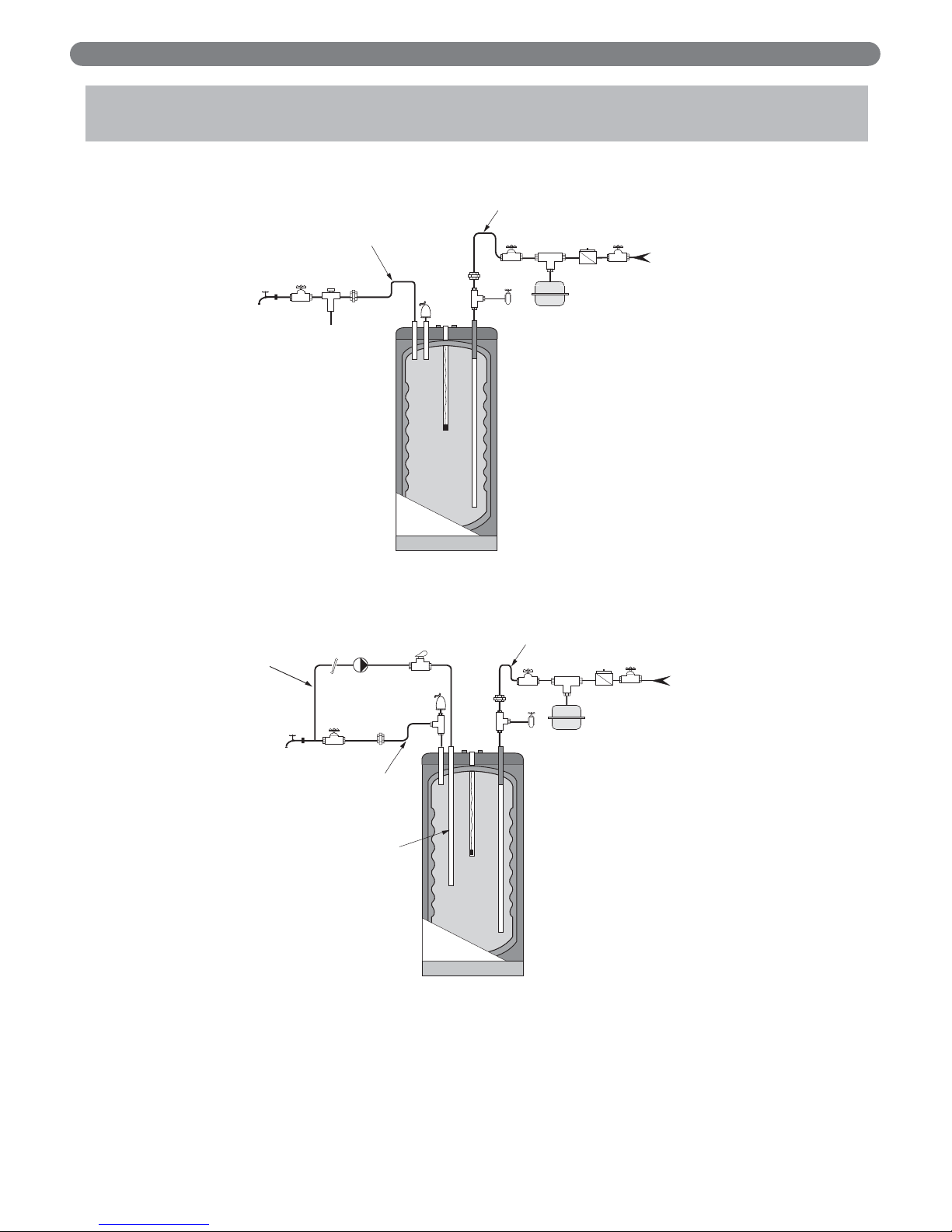
Figure 3.1: Peerless®Partner®Recommended Installation: Domestic Water Piping
Figure 3.2: Peerless®Partner®Recommended Installation: Domestic Water Piping with Recirculation
3. INSTALLATION – PIPING DRAWINGS
1. Shut-off valve
2. Recirculation Circulator
3. Flow Check Valve
4. T&P relief valve
5. Unions
6. Backflow preventer or pressure reducing valve(*)
9. Drain valve
10. Thermal expansion tank (potable)
11. Recirculation dip tube
13. Thermostatic mixing valve (*)
(*) Optional devices may be required by local codes.
INSTALLATION - PIPING DRAWINGS
5
12" min.
Heat Trap
Loop
(Optional)
1
9
Heat Trap
(Optional)
1
5
12" min.
Loop
9
10
6
10
Cold Water
1
1
6
12" min.
Heat Trap
Loop
(Optional)
13
H
M
1
Recirculating
Loop
C
1
Heat Trap
(Optional)
5
2
12" min.
Loop
4
3
4
5
11
Inlet
Cold Water
Inlet
Page 12

10
Figure 3.3: Domestic Water Drain Tube Assembly: Commonwealth of Massachusetts Requirements
Figure 3.4: Peerless®Partner®Domestic Water Piping: Commonwealth of Massachusetts Requirements
1. Shut-off valves
4. T&P relief valve
5. Unions
6. Backflow preventer or pressure reducing valve (*)
8. Vacuum breaker
9. Drain valve
10. Thermal expansion tank (potable)
11. Dip tube - Draining per Table 1.1
13. Mixing valve (*)
(*) Optional devices may be required by local codes.
INSTALLATION - PIPING DRAWINGS
12" min.
12" min.
Heat Trap
Loop
Heat Trap
Loop
(Optional)
(Optional)
Cold Water
13
H
M
1
5
C
4
5
8
9
10
1
6
Inlet
11
Page 13

11
Figure 3.5: Peerless®Partner®Boiler Piping with 3-Way Valve (Domestic Priority)
INSTALLATION - PIPING DRAWINGS
PIPING LEGEND
Page 14

12
Figure 3.7: Peerless®Partner®Boiler Piping with Zone Circulators
INSTALLATION - PIPING DRAWINGS
Figure 3.6: Peerless®Partner®Boiler Piping with Zone Valves
Page 15

13
INSTALLATION - PIPING DRAWINGS
Figure 3.9: Peerless®Partner®Boiler Piping for Peerless®PUREFIRE®Condensing Boilers
Note: Contact PB Heat for optional heat exchanger kit for "Double Wall" applications.
Figure 3.8: Peerless®Partner®Boiler Piping with Plate Heat Exchanger for “Double Wall” Applications
(Refer to the PureFire
®
Installation, Maintenance, and Operations Manual for alternate piping configurations).
Page 16

14
INSTALLATION - PIPING DRAWINGS
Figure 3.11: Multiple Peerless®Partner®Water Heater System Domestic Piping - Series
• Recommended for applications in which there is a
large water consumption in short period of time.
• A maximum of 3 water heaters may be piped in series.
• Utilize the lead (hot water outlet) Peerless
®
Partner
®
tank thermostat to control system temperature.
• Install automatic mixing valve at either the hot water
outlet of the water heater system or at each hot water
fixture.
• Each tank should be piped with a drain as shown in
Figure 3.1
Figure 3.10: Multiple Peerless®Partner®Water Heater System Domestic Piping - Parallel
• Recommended for most applications.
• Any one water heater tank thermostat may be
utilized to control system temperature.
• Install automatic mixing valve at either the hot
water outlet of the water heater system or at
each hot water fixture.
• Each tank should be piped with a drain as
shown in Figure 3.1.
Circulator
Recirculated
Water
Automatic
Mixing Valve
Hot Water
Outlet
Cold Water
Inlet
T&P
Relief
Valve
Cold Water
Inlet
Isolation
Valve
Cold Water
Inlet
Circulator
Isolation
Recirculated
Valve
Water
T&P
Relief
Valve
Automatic
Mixing Valve
Hot Water
Outlet
Cold Water
Inlet
Page 17

15
Figure 3.12: Recommended Multiple Peerless®Partner®Boiler Piping (Reverse Return)
INSTALLATION - PIPING DRAWINGS
Page 18

16
A. WIRING REQUIREMENTS
1. All wiring must be a minimum of 18 gauge and
installed in accordance with:
a. U.S.A. - National Electrical Code and any other
national, state or local code requirements having
jurisdiction.
b. Canada - C.S.A. C22.1 Canadian Electrical Code
Part 1 and any other national, provincial and local
code requirements having jurisdiction.
2. If original wire supplied with appliance must be
replaced, Type 90ºC or its equivalent must be used.
3. Refer to control component instructions packed with
boiler for application information.
4. An optional service switch may be installed in water
heater electrical circuit. This switch would only shut
off the water heater, not the home heating system. Do
not shut off water heater if there is a chance of
freezing.
5. All electrical contacts shown do not have power
applied - off the shelf condition. See Figures 5.1
through 5.9.
B. CIRCULATORS
Priority relay must be sized for total amp draw of all
circulators.
C. ZONE VALVES
Transformer must be sized for maximum load of all zone
valves.
D. SNAP SET CONNECTION
1. For easy wiring between water heater thermostat and
boiler controls see Installation Wiring section Figures
5.1 through 5.9.
2. Make sure snap set is firmly snapped together after
wiring.
Electrical shock hazard can cause severe personal
injury, death or substantial property damage.
Disconnect power before installing and/or servicing.
WARNING
4. INSTALLATION – WIRING
INSTALLATION - WIRING
Page 19

17
5. INSTALLATION – WIRING DRAWINGS
INSTALLATION – WIRING DRAWINGS
Figure 5.2: Typical 3-Wire Zone Valve Zoning, With
Domestic Priority
Figure 5.1: Typical 4-Wire Zone Valve Zoning, With
Domestic Priority
Page 20

18
INSTALLATION – WIRING DRAWINGS
Figure 5.4: Typical 3-Wire Zone Valve Zoning,
Without Domestic Priority
Figure 5.3: Typical 4-Wire Zone Valve Zoning,
Without Domestic Priority
24
V.A.C.
Page 21

19
2
INSTALLATION – WIRING DRAWINGS
Figure 5.5: Typical Circulator Zoning With
Domestic Priority
Figure 5.6: Typical Circulator Zoning Without
Domestic Priority
Page 22

20
INSTALLATION – WIRING DRAWINGS
Figure 5.7: Circulator Zoning Without Domestic Priority, Series MI
Figure 5.8: Circulator Zoning Without Domestic Priority, Series WBV/WV, WV-DV, EC, SC
Page 23

21
INSTALLATION – WIRING DRAWINGS
Figure 5.9: Priority Zoning Circulator Wiring
Note: Maximum of 4 total circulator zone
when wiring 1 zone for priority.
Page 24

22
6. WATER HEATER START-UP
A. FILLING THE INNER (DOMESTIC WATER)
TANK
1. Close domestic water drain valve.
2. Open domestic water isolation valves for water heater.
3. Vent air from inner (domestic water) tank by opening
nearest hot water faucet. Fill domestic water tank
completely by allowing water to run until there is a
constant flow of water.
4. Close hot water faucet.
B. FILLING THE OUTER (BOILER WATER)
TANK
1. Close boiler water drain valve at boiler water outlet of
water heater.
2. Open water heater’s boiler water isolation valves.
3. Allow air to escape from outer (boiler water) tank by
opening vent cap A on automatic air vent, located on
top of water heater. See Figure 6.1.
4. Follow instructions furnished with boiler to fill with
water.
5. When tank is full, air will stop escaping, and the
automatic air vent will close. If air vent does not seat
properly (water leaks out), remove cap A. Briefly push
in valve B and release it to clean valve seat. Screw
cap A on completely, then unscrew one turn. See
Figure 6.1.
6. If antifreeze is used in boiler water, check
concentration. Boiler water (including additives) must
be practically non-toxic, having toxicity rating or class
of 1, as listed in Clinical Toxicology of Commercial
Products.
– Install an automatic mixing valve at water
Never use water heater unless inner and outer tanks
are completely filled with water. Inner tank must be
completely filled and pressurized before pressurizing
outer tank.
CAUTION
Never use water heater unless inner and outer tanks
are completely filled with water. Inner tank must be
completely filled and pressurized before pressurizing
outer tank.
CAUTION
For proper operation of the water heater, be sure the
top cap is tightened at all times.
NOTICE
Do not use automotive, ethylene glycol or petroleumbased antifreeze. Do not use any undiluted
antifreeze. This can cause severe personal injury,
death or substantial property damage.
WARNING
Figure 6.1: Automatic Air Vent
WATER HEATER START-UP
DANGER
HOT WATER CAN SCALD!
• Water temperatures over 125°F can cause severe
burns instantly, or death from scalds.
• Feel water before bathing or showering.
• Consumer Product Safety Commission and some
states recommend temperatures settings of 130ºF
or less. Setting thermostat higher than 130ºF will
increase risk of scald injury and cause severe
personal injury or death.
• Water heated to a temperature suitable for clothes
washing, dish washing and other sanitizing needs
will scald and cause permanent injury.
• Children and elderly, infirm, or physically
handicapped persons are more likely to be injured
by hot water. Never leave them unattended in or
near a bathtub. If anyone using hot water in the
building fits this description, or if state laws or
local codes require certain water temperatures at
hot water faucets, take special precautions.
Page 25

23
C. GENERAL NOTES
• Household water usage patterns will affect water
temperature at any faucet or shower. Occasionally
check temperature at each point of use, then adjust
thermostat accordingly. Always recheck temperature
after adjusting thermostat.
• When hot water is used in repeated small quantities, a
“stacking” effect can develop in the water heater. The
upper layer of water in tank can be hotter than lower
layer.
• Lowering the thermostat setting or installing automatic
mixing valves as indicated in these instructions will
reduce water temperature levels. Consult your installer
or service technician.
D. ADJUSTING THE WATER HEATER
THERMOSTAT
Water heater thermostat is factory set to its lowest
temperature.This may or may not be suitable for your
needs.
Turn thermostat knob clockwise to increase water
temperature.
Turn thermostat knob counter-clockwise to
decrease water temperature.
• Measure water temperature at a hot water faucet
immediately after first heating cycle. Further
temperature adjustment may be necessary as water
heating system is used. Recheck water temperature at
faucet after adjustment.
• When adjusting thermostat, be sure boiler limit control
is set a minimum of 20ºF higher.
WATER HEATER START-UP
At no time should boiler limit control be set above
210°F. This can cause severe personal injury, death or
substantial property damage if ignored.
WARNING
Studies have indicated that dangerous bacteria,
including legionella, pneumophila, can form in the
potable water distribution system if certain minimum
water temperatures are not maintained. Contact your
local health department for more information.
WARNING
Figure 6.2: Peerless®Partner®Knob
DANGER
HOT WATER CAN SCALD!
– Install an automatic mixing valve at water heater or
at each hot water faucet, bath and shower outlet.
Selection and installation must comply with valve
manufacturer’s recommendation and instructions.
– Use the lowest practical temperature setting.
– Measure water temperature at hot water faucet after
any adjustment. You must follow “Adjusting the
Water Heater Thermostat” procedures.
Page 26

24
7. WATER HEATER MAINTENANCE
WATER HEATER MAINTENANCE
A. MAINTENANCE SCHEDULE
Annual service by qualified service technician should include
the following:
1. Any procedure required by local codes.
2. Check air vent operation.
3. Verify system pressure. Air venting procedure may
require adding water to bring system up to pressure,
typically 12 psig.
4. Manually operate T&P relief valve at least once a
year. This will release some hot water.
5. Move operating lever to open position for a few
seconds and then move it back, allowing it to snap
closed. After T&P relief valve is operated, if it
continues to release water, close cold water inlet to
water heater immediately. Follow draining instructions,
and replace T&P relief valve. If T&P relief valve
weeps periodically, it may be due to thermal
expansion see Thermal Expansion, page 5. Do not
plug T&P relief valve or discharge piping.
6. Follow instructions on circulator to oil it, if required.
7. Check mixing valve, valves, pipes and fittings for
leaks.
8. Check function of field-installed controls and valves.
See component manufacturer’s instructions.
9. Review homeowner’s maintenance responsibilities and
their frequencies, including any not listed in the
following section.
Homeowner monthly maintenance to include:
• Check air vent operation.
Automatic air vent - remove cap. Briefly push in
valve and release it to clean valve seat. Screw cap
on completely, then unscrew one full turn. If air
vent does not operate, call qualified service
technician.
• Visually check valves, pipes and fittings for leaks. Call
qualified service technician to repair leaks.
B. FILLING WATER HEATER
See “Filling the Inner (Domestic Water) Tank and “Filling the
Outer (Boiler Water) Tank” on in Section 6.A and 6.B.
C. DRAINING WATER HEATER
Drain water heater if it will be shut off and exposed to freezing
temperatures. Freezing water will expand and damage water
heater.
• If boiler water contains sufficient antifreeze, then only
the domestic water needs to be drained.
• If boiler water does not contain sufficient antifreeze,
then the boiler water and domestic water must be
drained.
If antifreeze is used in boiler water, check concentration.
Boiler water (including additives) must be practically nontoxic, having toxicity rating or class of 1, as listed in
Clinical Toxicology of Commercial Products. A maximum
50/50 mixture of inhibited propylene glycol is
recommended. Follow antifreeze manufacturer’s
instruction.
Before operating T&P relief valve, make sure no one
is in front of or around T&P relief valve discharge piping. Hot discharge water can cause severe personal
injury or substantial property damage.
WARNING
DANGER
Plugging T&P relief valve or discharge piping can
cause excessive pressure in water heater, resulting
in severe personal injury, death, or substantial
property damage.
Close boiler water isolation valves and relieve
system pressure to below 15 psig in outer tank
before draining inner tank to prevent damage to
inner tank.
WARNING
Do not use automotive, ethylene glycol or petroleumbased antifreeze. Do not use any undiluted
antifreeze. This can cause severe personal injury,
death or substantial property damage.
WARNING
Water from opened drain valves, unions and other
connections may be extremely hot. To avoid severe
personal injury, death or substantial property
damage:
- Tighten all drain hose connections.
- Direct hot water away from all persons.
WARNING
Page 27

25
D. DRAINING INNER (DOMESTIC WATER)
TANK
(See Domestic Piping Fig. 3.1)
1. Disconnect snap set wiring connection at water heater.
a. If outer (boiler water) tank pressure is greater than
15 psig, relieve boiler pressure and close isolation
valves before proceeding.
2. Close system supply isolation valve.
3. Connect a hose to domestic water drain valve at cold
water inlet. Hose should extend to drain at floor level
to allow siphoning of domestic water tank.
4. Open hot water faucet at highest point above heater.
5. Open domestic water drain valve to start siphoning.
6. When draining is complete, close hot water faucet and
domestic water drain valve.
E. DRAINING OUTER (BOILER WATER) TANK
1. Disconnect snap set wiring connection at water.
2. Close boiler water isolation valves between boiler and
water heater.
3. Connect hose to boiler water drain valve at water
heater. Open and drain water to a safe place.
4. To speed draining procedure, loosen air vent on top
of tank.
5. When draining is complete, close drain valve and
retighten air vent.
WATER HEATER MAINTENANCE
Page 28

26
8. TROUBLESHOOTING
TROUBLESHOOTING
Table 8.1: Troubleshooting
Problem Cause Solution
No hot water at faucet.
Boiler does not operate
Refer to boiler installation instructions
Check main service switch
Check fused disconnect
Circulator does not operate
Check power supply
Check circulator switching relay
Improper tank thermostats setting or calibration Turn tank thermostat to higher setting
Zone valve does not open (if used) Check power supply
Electrical problem (relay, wiring, fuse, etc.)
Check fuse and replace
Check circuit breaker and reset (if applicable)
Check power supply
Air trapped in boiler supply to tank Purge piping
Insufficient hot water.
Tank thermostat Adjust thermostat to higher setting
Undersized boiler with no priority to domestic
hot water
Rewire for priority
Peak use of hot water is greater than tank
storage capacity
Determine peak usage and compare to tank volume
Undersized circulator Check recommended circulator size in Table 11.1 and 11.2
Faulty tank thermostat Replace thermostat
Water at faucet too hot.
Tank thermostat set too high Lower thermostat setting
Improper system plumbing Compare plumbing to Section 3
Improper system wiring Compare wiring to Section 4
Tank thermostat faulty Replace thermostat
Excessive boiler cycling
per day during summer.
Large demand Reduce demand or consider larger tank
Faulty tank thermostat Replace thermostat
Boiler high limit set too low Increase boiler high limit setting
Page 29

27
9. REPAIR PARTS
REPA IR PART S
Table 9.1: Repair Parts
Description Models
Stock
Code
1 Air Vent, Automatic All 51329
2
Thermostat - 160°F Residential All 51330
Thermostat - 194°F Commercial All 51331
3 Bottom Cap
PT-30, 40, 50, 60 51332
PT-80 51333
PT-120 51334
4 To p
PT-30, 40, 50, 60 51335
PT-80 51336
PT-120 51337
5 Thermostat Drywell
PT-30 51338
PT-40
51339
PT-50
51340
PT-60, PT-80
51341
PT-120
51342
6
Dip Tube
PT-30
51343
PT-40 51344
PT-50 51345
PT-60 51346
PT-80 51347
PT-120 51348
Page 30

28
REPA IR PART S
Figure 9.1: Peerless®Partner® Tank Components
Figure 9.2: Thermostat Cover Plate Assembly
Page 31

29
10.
WATER HEATER DIMENSIONS & RATINGS
WATER HEATER DIMENSIONS & RATINGS
Figure 10.1: Top View
Figure 10.2: Rear View
Table 10.1
PEERLESS®PARTNER®DIMENSIONS & RATINGS
Water
Heater
Model
Number
Capacity
(gallons)
Heating
Surface
(sq. ft.)
Boiler
Head
Loss at
Min.
Flow
(Ft. of
Water)
Piping Connections
(NPT)
Dimensions (inches)
Thermo-
stat
Drywell
Length
(inches)
Empty
Wei gh t
(lbs.)
Domes-
tic Boiler
Domes-
tic Boiler Aux. A B C D E F
PT-30 28 5 13 .75
³⁄₄
1
³⁄₄
38 9 30 22 14 6 25 115
PT-40 39 6 16 1.0
³⁄₄
1
³⁄₄
46 9 38 22 14 6 29 135
PT-50 46 8 20 1.25
³⁄₄
1¹⁄₄
³⁄₄
57 9 49 22 14 6 37 165
PT-60 56 8 24 1.50
³⁄₄
1¹⁄₄
³⁄₄
66 9 58 22 14 6 47 190
PT-80 70 14 29 2.0
1¹⁄₂ 1¹⁄₂ 1¹⁄₂
61 10
50¹⁄₂
26
10¹⁄₂ 10¹⁄₂
47 271
PT-120 119 43 42 2.50
1¹⁄₂
2
1¹⁄₂
72 10 64 32
10¹⁄₂
5 51 479
C
Page 32

30
Table 11.2
Table 11.1
11. PERFORMANCE RATINGS
Water Heater
Model Number
Boiler Heating
Capacity MBH
Peak Flow
Gallon/10 Minute
1st Hour Flow
Gallon/Hour
Continuous Flow
Gallon/Hour
Circulator
Minimum GPM
PT-30
PT-40
PT-50
PT-60
PT-80
PT-120
102
131
164
316
351
492
54
69
87
142
164
246
210
271
339
628
704
1003
188
242
302
583
648
907
10
13
16
32
35
49
Conditions: 50°F Domestic Cold Water Inlet Temperature
115°F Domestic Hot Water Outlet Temperature
200°F Boiler Water Supply Temperature
Water Heater
Model Number
Boiler Heating
Capacity MBH
Peak Flow
Gallon/10 Minute
1st Hour Flow
Gallon/Hour
Continuous Flow
Gallon/Hour
Circulator
Minimum GPM
PT-30
PT-40
PT-50
PT-60
PT-80
PT-120
87
112
140
270
300
420
42
54
68
105
123
189
138
178
224
405
456
655
116
149
187
360
400
560
9
11
14
27
30
42
Conditions: 50°F Domestic Cold Water Inlet Temperature
140°F Domestic Hot Water Outlet Temperature
200°F Boiler Water Supply Temperature
Table 11.3
Water Heater
Model Number
Boiler Heating
Capacity MBH
Peak Flow
Gallon/10 Minute
1st Hour Flow
Gallon/Hour
Continuous Flow
Gallon/Hour
Circulator
Minimum GPM
PT-30
PT-40
PT-50
PT-60
PT-80
PT-120
67
86
107
206
229
321
37
48
61
91
107
167
111
143
180
320
362
523
89
114
143
275
306
428
7
9
11
21
23
32
Conditions: 50°F Domestic Cold Water Inlet Temperature
140°F Domestic Hot Water Outlet Temperature
180°F Boiler Water Supply Temperature
Table 11.4
Water Heater
Model Number
Boiler Heating
Capacity MBH
Peak Flow
Gallon/10 Minute
1st Hour Flow
Gallon/Hour
Continuous Flow
Gallon/Hour
Circulator
Minimum GPM
PT-30
PT-40
PT-50
PT-60
PT-80
PT-120
82
106
132
255
284
397
48
61
78
123
143
217
174
224
281
516
579
828
152
195
244
471
523
733
8
11
13
26
28
40
Conditions: 50°F Domestic Cold Water Inlet Temperature
115°F Domestic Hot Water Outlet Temperature
180°F Boiler Water Supply Temperature
PERFORMANCE RATINGS
Page 33

31
PERFORMANCE RATINGS
Table 11.5 First Hour Ratings for Reduced Boiler Output (Gallons)
Boiler
Output
(MBH)
PT-30 PT-40 PT-50 PT-60 PT-80 PT-120
140°F 115°F 140°F 115°F 140°F 115°F 140°F 115°F 140°F 115°F 140°F 115°F
40 76 96 82 103 90 111 98 119 109 130 149 169
50 89 115 95 121 103 129 111 137 123 148 162 188
60 102 133 109 140 117 148 125 156 136 167 175 206
70 116 152 122 158 130 166 138 174 149 185 189 224
80 129 170 135 176 143 184 151 192 163 204 202 243
90 --- 189 149 195 157 203 165 211 176 222 215 261
100 --- 207 162 213 170 221 178 229 189 241 229 280
120 --- --- --- 250 197 258 205 266 216 278 255 317
140 --- --- --- --- 223 295 231 303 243 314 282 354
160 --- --- --- --- --- 332 258 340 269 351 309 391
180 --- --- --- --- --- --- 285 377 296 388 335 428
200 --- --- --- --- --- --- 311 414 323 425 362 464
220 --- --- --- --- --- --- 338 451 349 462 389 501
240 --- --- --- --- --- --- 365 488 376 499 415 538
260 --- --- --- --- --- --- 391 525 403 536 442 575
280 --- --- --- --- --- --- --- 562 429 573 469 612
300 --- --- --- --- --- --- --- 599 456 610 495 649
340 --- --- --- --- --- --- --- --- --- 684 549 723
380 --- --- --- --- --- --- --- --- --- --- 602 797
420 --- --- --- --- --- --- --- --- --- --- 655 871
460 --- --- --- --- --- --- --- --- --- --- --- 944
Note: shaded values are recommended only for PureFire®and Pinnacle®boilers due to potential for condensation.
Page 34

32
NOTES
Page 35

Partner
®
Water Heater
Peerless
®
Indirect-Fired
Installation,
Operation &
Maintenance
Manual
TO THE INSTALLER:
This manual is the property of the owner and
must be affixed near the water heater for
future reference.
TO THE OWNER:
This water heater should be inspected annually
by a Qualified Service Agency.
PB HEAT, LLC
131 S. CHURCH STREET • BALLY, PA 19503
PT-30 PT-40 PT-50
PT-60 PT-80 PT-120
X8167 R0 (12/11-2M)
Printed in U.S.A.©2011 PB Heat, LLC. All rights reserved.
 Loading...