

Peerless-AV KIP655-S-EUK, KIP655-RAL9007, KIP655-NR, KIP655, KIP655-EUK Installation Instructions
...
ENG
1
2015-04-28 #:150-9052-3 (2017-07-12)
WARNING
ENG - Do not begin to install product until you have read and understood the instructions and warnings
contained in this user guide. This product is designed to be installed on wood stud, solid concrete or cinder
block walls. Hardware is included for wood stud, solid concrete and cinder block installation. Before installing
make sure the supporting surface will support the combined load of the equipment and hardware. Screws must
be tightly secured. Do not overtighten screws or damage can occur and product may fail. Never exceed the
Maximum Load Capacity. Always use an assistant or mechanical lifting equipment to safely lift and position
equipment. This product is intended for indoor use only. Use of this product outdoors could lead to product
failure or personal injury. To reduce the risk of electric shock or re, do not expose product to water or moisture.
Be sure power cord is routed so that it will not be tripped on, stepped on, or pinched by heavy items. Avoid
overloading electrical outlets or extension cords. Always disconnect the power cord from the power outlet
when installing, servicing, or not using the product for an extended period of time. Do not block ventilation
slots or fan exhaust on product. Blocking airow could damage product. Arrange product to allow air to ow
freely around product. Keep product away from direct sunlight or any source of heat. For support please call
800-4-SIGNAGE.
ENG
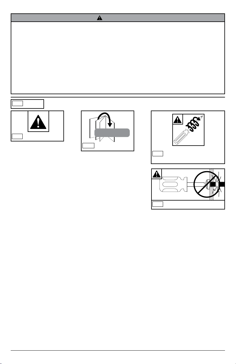
Symbols
ENG
WARNING
ENG
#
Skip to step.
x3
Screws must get at least three
ENG
full turns and t snug.
ENG
Do not overtighten screws.
2
2015-04-28 #:150-9052-3 (2017-07-12)
ENG
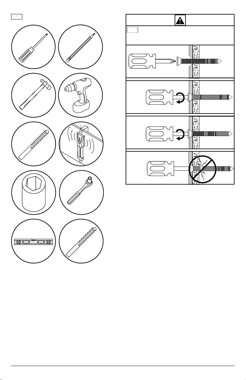
Tools Needed for Assembly.
To properly tighten screws: Tighten until screw
ENG
head makes contact, then tighten another 1/2
turn. Do not overtighten screws.
1
2
5/32"
(4mm)
3
+1/2
4
3/8"
(10mm)
5/16"
(8mm)
3
2015-04-28 #:150-9052-3 (2017-07-12)
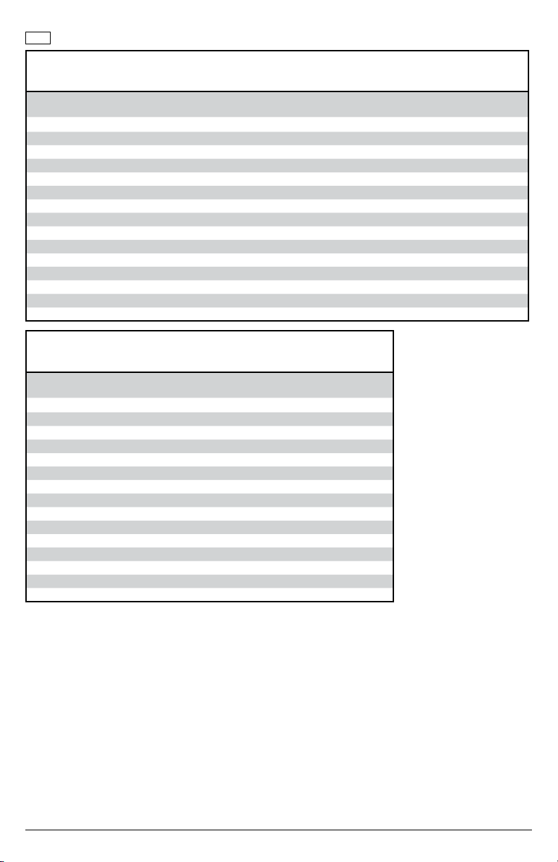
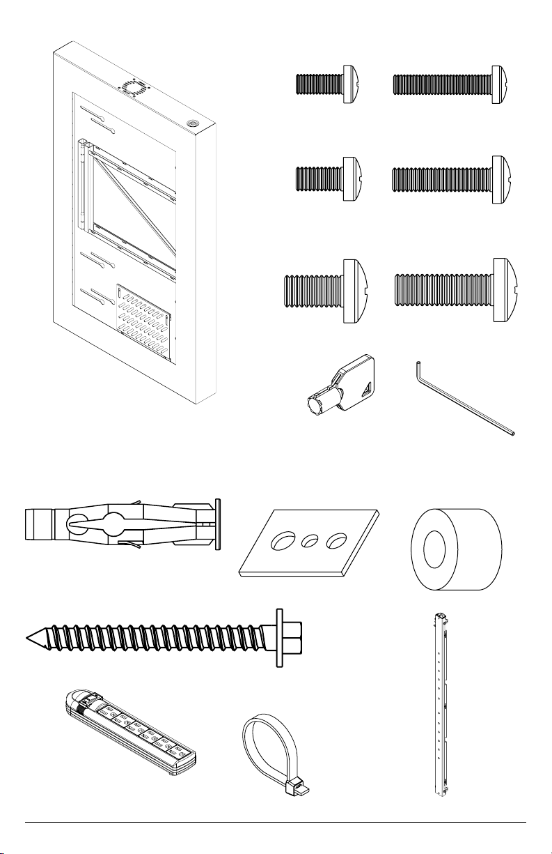
Parts (Before beginning, make sure you have all parts shown below).
ENG
Parts List
A kiosk BLK
kiosk SLV
B M5 x 12mm pan phl screw 4 520-1027 520-1027 520-1027 520-1027 520-1027
C M5 X 25mm pan phl screw 4 520-9543 520-9543 520-9543 520-9543 520-9543
D M6 x 12mm pan phl screw 4 520-1128 520-1128 520-1128 520-1128 520-1128
E M6 x 25mm pan phl screw 4 520-1208 520-1208 520-1208 520-1208 520-1208
F M8 x 12mm pan phl screw 4 520-9571 520-9571 520-9571 520-9571 520-9571
G M8 x 25mm pan phl screw 4 520-1031 520-1031 520-1031 520-1031 520-1031
H M5/M4/M6 multi washer 4 580-1398 580-1398 580-1398 580-1398 580-1398
I 1/4"spacer 4 540-1059 540-1059 540-1059 540-1059 540-1059
J key 2 565-0049A 565-0049A 565-0049A 565-0049A 565-0049A
K 4mm allen wrench 1 560-9646 560-9646 560-9646 560-9646 560-9646
L 8mm concrete anchor 4 590-0320 590-0320 590-0320 590-0320 590-0320
M #14 x 2.5" wood screw 4 5S1-015-C03 5S1-015-C03 5S1-015-C03 5S1-015-C03 5S1-015-C03
N adaptor bracket 2 150-T1689 150-T1689 150-T1689 150-T1689 150-T1689
O power strip 1 600-0370 600-0370 600-0370 600-0370 600-0370
P cable tie 6 560-1756 560-1756 560-1756 560-1756 560-1756
KIP640
KIP640-S
Part #
1 150-P1706
150-4706
KIP642
KIP642-S
Part #
150-P1707
150-4707
KIP643
KIP643-S
Part#
150-P1658
150-4658
KIP646
KIP646-S
Part #
150-P1702
150-4702
KIP647
KIP647-S
Part #Description Qty
150-P1703
150-4703
Parts List
A kiosk BLK
kiosk SLV
B M5 x 12mm pan phl screw 4 520-1027 520-1027 520-1027
C M5 X 25mm pan phl screw 4 520-9543 520-9543 520-9543
D M6 x 12mm pan phl screw 4 520-1128 520-1128 520-1128
E M6 x 25mm pan phl screw 4 520-1208 520-1208 520-1208
F M8 x 12mm pan phl screw 4 520-9571 520-9571 520-9571
G M8 x 25mm pan phl screw 4 520-1031 520-1031 520-1031
H M5/M4/M6 multi washer 4 580-1398 580-1398 580-1398
I 1/4"spacer 4 540-1059 540-1059 540-1059
J key 2 565-0049A 565-0049A 565-0049A
K 4mm allen wrench 1 560-9646 560-9646 560-9646
L 8mm concrete anchor 4 590-0320 590-0320 590-0320
M #14 x 2.5" wood screw 4 5S1-015-C03 5S1-015-C03 5S1-015-C03
N adaptor bracket 2 150-T1689 150-T1689 150-T1689
O power strip 1 600-0370 600-0370 600-0370
P cable tie 6 560-1756 560-1756 560-1756
KIP648
KIP648-S
Part #
1 150-P1704
150-4704
KIP649
KIP649-S
Part #
150-P1815
150-4815
KIP655
KIP655-S
Part#Description Qty
150-P1705
150-4705
4
2015-04-28 #:150-9052-3 (2017-07-12)
A
(1)
kiosk
B (4)
M5 x 12 mm
C (4)
M5 x 25 mm
(4)
L
8mm concrete anchor
D (4)
M6 x 12 mm
F (4)
M8 x 12 mm
(2)
J
key
H (4)
M5/M4/M6 washer
E (4)
M6 x 25 mm
G (4)
M8 x 25 mm
(1)
K
allen
wrench
I (4)
spacer
(4)
M
#14 x 2-1/2" wood screw
(1)
O
power strip
P (6)
cable tie
5
(2)
N
adaptor bracket
2015-04-28 #:150-9052-3 (2017-07-12)

ENG
This page intentionally left blank.
6
2015-04-28 #:150-9052-3 (2017-07-12)

1
A
J
(2)
2
A
7
2015-04-28 #:150-9052-3 (2017-07-12)

3
ENG
Wood stud wall.
ENG
Concrete/Cinder block.
3a
3b
3a
WARNING
ENG - When installing Peerless wall mounts on a wood stud wall covered with gypsum board (drywall), verify that
the wood studs are a minimum of 2" x 4" nominal size. Do not install over gypsum board thicker than 5/8".
ENG
3a-1
3a-2
ENG
Level wallplate. Mark mounting holes on stud
center lines.
A
Use stud nder to locate and
mark stud center lines.
8
2015-04-28 #:150-9052-3 (2017-07-12)

3a-3
2.5"
(64mm)
5/32"
(4mm)
ENG
Drill mounting holes into supporting surface
(2.5" (64 mm) minimum depth required).
3a-4
ENG
Level wallplate. Install using wood screws
provided.
ENG
Maximum 80 in. • lb (9 N.M.).
5/32"
(4mm)
ENG
Mounting hole must center on stud.
3/8"
(10mm)
A
M (4)
4
9
2015-04-28 #:150-9052-3 (2017-07-12)

3b
WARNING
ENG - When installing Peerless wall mounts on a concrete wall, the wall must be at least 8" thick with a minimum
compressive strength of 2000 psi. When installing Peerless wall mounts on a cinder block wall, the cinder blocks
must meet ASTM C-90 specications and have a minimum nominal width of 8". Do not drill into mortar joints!
Be sure to mount in a solid part of the block, generally 1" (25 mm) minimum from the side of the block. It is
suggested that a standard electric drill on slow setting is used to drill the hole instead of a hammer drill to avoid
breaking out the back of the hole when entering a void or cavity. Never attach concrete expansion anchors to
concrete or cinder block covered with plaster, drywall or other nishing material.
3b-1
ENG
Level wallplate. Mark mounting holes.
A
3b-2
5/16"
(8mm)
ENG
Drill mounting holes into supporting surface
(2.5" (64 mm) minimum depth required).
10
ENG
Do not drill into mortar joints.
2015-04-28 #:150-9052-3 (2017-07-12)
5/16"
(8mm)
2.5"
(64mm)

3b-3
L (4)
3b-4
3/8"
(10mm)
L
Insert anchor ush to concrete.
ENG
ENG
Maximum 80 in. • lb (9 N.M.).
ENG
Level wallplate. Install using concrete
anchors and wood screws provided.
A
11
M (4)
2015-04-28 #:150-9052-3 (2017-07-12)

4
ENG
Center adaptor brackets vertically on back of screen.
5
x3
ENG
Use of spacers is optional.
X
N (2)
X
C (4)
H (4)
G (4)
I (4)
I (4)
D (4)
E (4)
H (4)
H (4)
I (4)
B (4)
H (4)
F (4)
12
2015-04-28 #:150-9052-3 (2017-07-12)

6
7
ENG
Note: Mounting Arm swings out to access
adapter brackets and behind display
13
2015-04-28 #:150-9052-3 (2017-07-12)

8
K
14
2015-04-28 #:150-9052-3 (2017-07-12)

9
10
J
(2)
A
KIP640, KIP640-S, KIP642, KIP642-S, KIP643, KIP643-S, KIP646, KIP646-S, KIP647, KIP647-S, KIP648,
KIP648-S, KIP649, KIP649-S, KIP655, KIP655-S
15
2015-04-28 #:150-9052-3 (2017-07-12)

Peerless Industries, Inc. (“Peerless”) warrants to original end-users of Peerless® products will be free from defects in material and
LIMITED FIVE-YEAR WARRANTY
workmanship, under normal use, for a period of ve years from the date of purchase by the original end-user (but in no case longer than
six years after the date of the product's manufacture). At its option, Peerless will repair or replace, or refund the purchase price of, any
product which fails to conform with this warranty.
In no event shall the duration of any implied warranty of merchantability or tness for a particular purpose be longer than the
period of the applicable express warranty set forth above. Some states do not allow limitations on how long a implied warranty lasts,
so the above limitation may not apply to you.
This warranty does not cover damage caused by (a) service or repairs by the customer or a person who is not authorized for such service
or repairs by Peerless, (b) the failure to utilize proper packing when returning the product, (c) incorrect installation or the failure to follow
Peerless' instructions or warnings when installing, using or storing the product, or (d) misuse or accident, in transit or otherwise, including
in cases of third party actions and force majeure.
In no event shall Peerless be liable for incidental or consequential damages or damages arising from the theft of any product,
whether or not secured by a security device which may be included with the Peerless
exclusion or limitation of incidental or consequential damages, so the above limitation or exclusion may not apply to you.
This warranty is in lieu of all other warranties, expressed or implied, and is the sole remedy with respect to product defects. No dealer,
distributor, installer or other person is authorized to modify or extend this Limited Warranty or impose any obligation on Peerless in
connection with the sale of any Peerless
This warranty gives specic legal rights, and you may also have other rights which vary from state to state.
®
product.
Patent Pending
®
product. Some states do not allow the
Peerless-AV
2300 White Oak Circle
Aurora, IL 60502
Email: tech@peerlessmounts.com
Ph: (800) 865-2112
Fax: (800) 359-6500
www.peerless-av.com
© 2017, Peerless Industries, Inc.
Peerless-AV Europe
Unit 3 Watford Interchange,
Colonial Way, Watford, Herts,
WD24 4WP, United Kingdom
Customer Care
44 (0) 1923 200 100
www.peerless-av.com
© 2017, Peerless Industries, Inc.
Peerless-AV de Mexico
Ave de las Industrias 413
Parque Industrial Escobedo
Escobedo N.L Mexico 66062
Servicio al Cliente
01-800-849-65-77
www.peerless-av.com
© 2017, Peerless Industries, Inc.
 Loading...