

Page 1
Installation and Assembly - Flat Panel Desktop Swivel
Mount
IMPORTANT! Read entire instruction sheet before you start installation and assembly.
Model: FDS-3250
FDS-3250-S
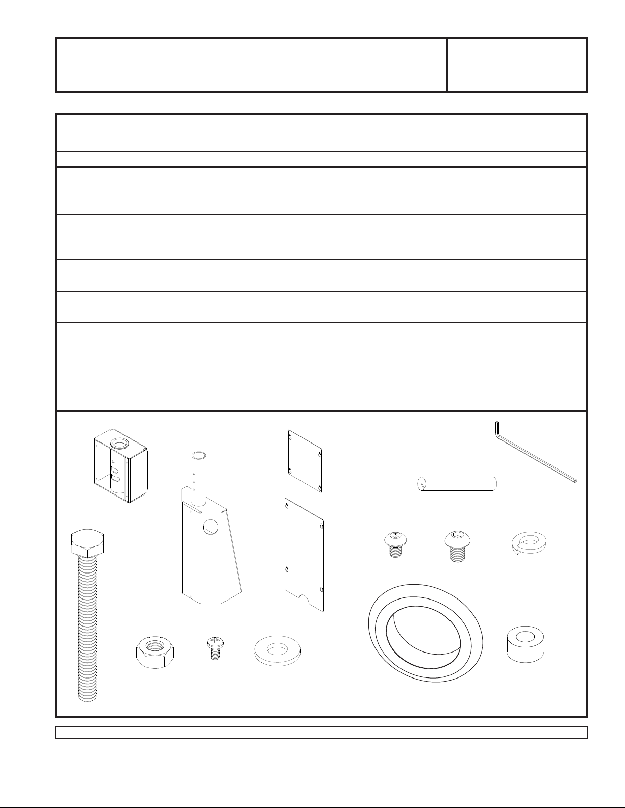
Parts List
Note: Some parts may appear slightly different than illustrated.
DESCRIPTION QTY. Part No. Part No.
A rotation box 1 090-1312 090-4312
B base 1 090-1303 090-4303
C rotation box cover 1 090-1304 090-4304
D base cover 1 090-1305 090-4305
E M5 x 10 mm socket pin screw 8 520-1164 520-2031
F M10 x 15 mm screw bolt 4 520-9262 520-9262
G 4 mm security allen wrench 1 560-9646 560-9646
H 1/4 x 2.5” screw bolt 4 520-1322 520-1322
I 1/4 hex nut 4 530-9302 530-9302
J 1/4-20 x 1/2” screw bolt 1 510-9108 510-9108
K 1/4” flat washer 8 540-9440 540-9440
L rubber grommet 2 560-1168 560-1168
M 1/2” spacer 1 590-1050 590-1050
N split washer 4 540-9402 540-9402
O rubber edge trim 1 560-1169 560-1169
FDS-3250
FDS-3250-S
A
H
C
B
O
D
E
I
Before you start make sure all parts listed are included with your product.
J
K L
F
G
N
M
1 of 4
Visit the Peerless Web Site at www.peerlessmounts.com For customer service call 1-800-729-0307 or 708-865-8870.
ISSUED: 03-07-06 SHEET #: 090-9110-5 11-20-08
Page 2
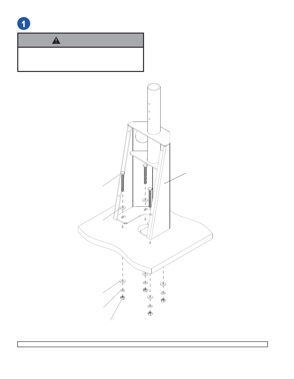
Attach base (B) to desktop using four 1/4 x 2.5” screw bolts (H), eight 1/4” flat washers (K), four split washers
(N), and four 1/4 hex nuts (I) as shown below.
WARNING
• Installer must verify that the mounting surface is a
minimum of 3/4” (19 mm) thick.
H
K
K
N
B
I
2 of 4
Visit the Peerless Web Site at www.peerlessmounts.com For customer service call 1-800-729-0307 or 708-865-8870.
ISSUED: 03-07-06 SHEET #: 090-9110-5 11-20-09
Page 3

Insert rubber grommets (L) into cord management holes in base (B) as shown below.
L
B
Attach adapter plate (not included) to rotation box (A) by using four M10
x 15 mm screw bolts (F). Att ach rot ation box (A) to base (B) as shown
below.
Note: See adapter plate instructions on how
to attach adapter plate to screen.
Note: Plastic bushing may come loose
during shipment. Bushing may need to be
re-inserted for proper function of the
product.
F
A
B
3 of 4
Visit the Peerless Web Site at www.peerlessmounts.com For customer service call 1-800-729-0307 or 708-865-8870.
ISSUED: 03-07-06 SHEET #: 090-9110-5 11-20-08
Page 4

T o restrict swivel insert one 1/4-20 x 1/2” screw
bolt (J) and one 1/2” spacer (M) into appropriate
slot as shown below in detail 1.
0°
40°
60°
DETAIL 1
M
J
Run cords from screen through cord management holes
in base (B) as shown below.
Note: In order to run cords through cord management hole, there
must be a hole cut into the desktop to allow the cords to exit the
mount.
A
cord management holes
B
Pre-install eight M5 x 10 mm socket pin screws (E) in
rotation box (A) and base (B) leaving 1/8” thread
exposed as shown in detail 2. Hook keyhole slots of
rotation box cover (C) and base cover (D) over exposed
thread of screws. Tighten all eight M5 x 10 mm socket
pin screws (E) with security allen wrench (G). Attach
rubber edge trim (O) to base cover (D).
B
1/8”
DETAIL 2
E
A
C
B
D
O
4 of 4
Visit the Peerless Web Site at www.peerlessmounts.com For customer service call 1-800-729-0307 or 708-865-8870.
© 2006 Peerless Industries, Inc. All rights reserved.
Peerless is a registered trademark of Peerless Industries, Inc.
All other brand and product names are trademarks or registered trademarks of their respective owners.
ISSUED: 03-07-06 SHEET #: 090-9110-5 11-20-09
 Loading...