

Page 1
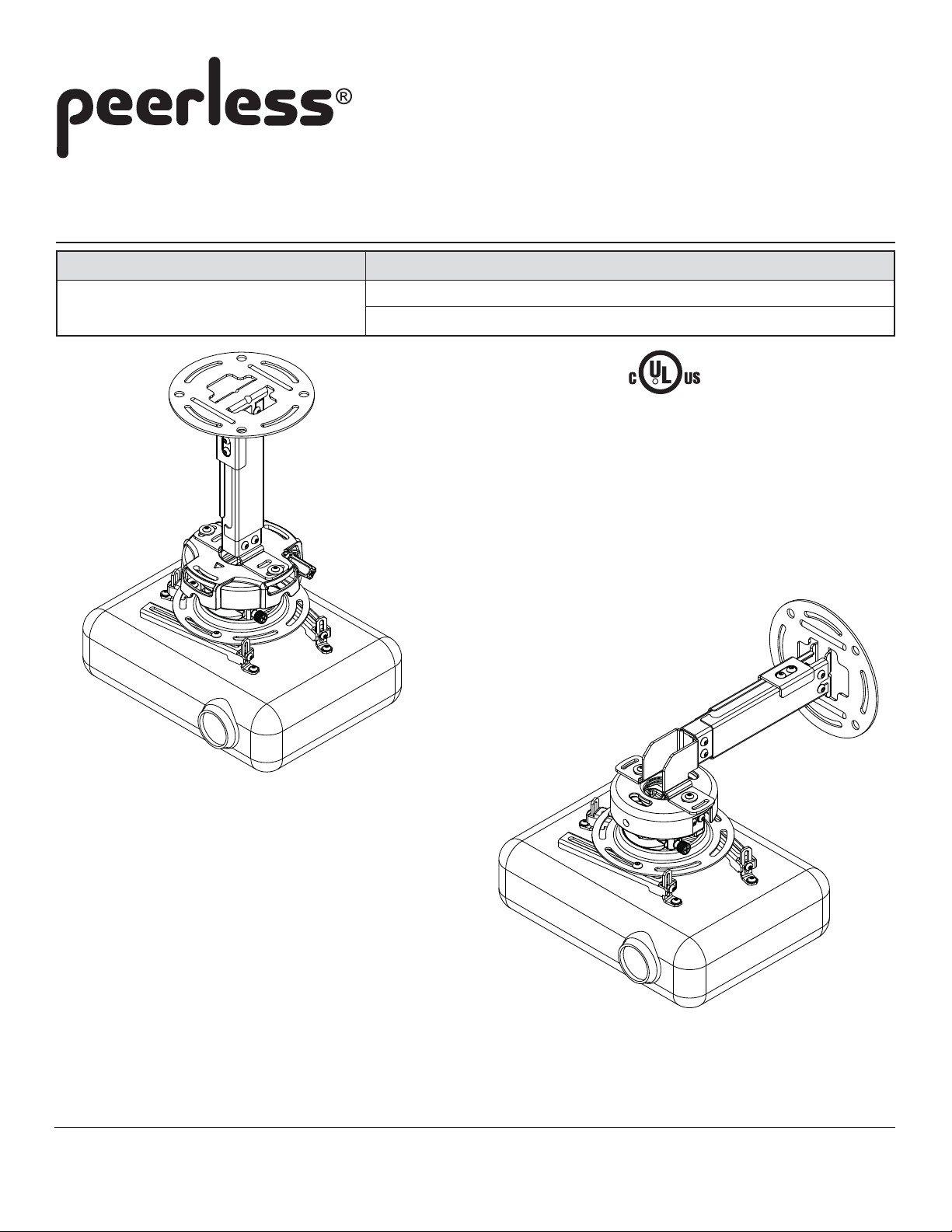
Installation and Assembly:
Projector Ceiling/Wall Mount
Model# Max UL Load Capacity
EXA, EXA-S, EXA-W, EXB, EXB-S, used with PRS projector mount 25 lb (11.3 kg)
EXB-W, EXC, EXC-S, EXC-W used with PRG projector mount 50 lb (22.7 kg)
This product is intended for use with UL
R
Installed to
Ceiling
Listed products and must be installed by a
qualified professional installer.
Shown with PRG
projector mount and
projector (not included)
Features:
• For use with PRG-UNV and PRS-UNV Projector Mounts
• EXA and EXB series for ceiling or wall mounting
• EXC models for ceiling mounting
• Integrated cable management
• V arious height adjustments for ideal viewing positions
Installed to Wall
(EXC models are not wall mountable
due to its extensive reach)
Shown with PRS
projector mount and
projector (not included)
1 of 11
Visit the Peerless Web Site at www.peerlessmounts.com
3215 W. North Ave. • Melrose Park, IL 60160 • (800) 865-2112 or (708) 865-8870 • Fax: (708) 865-2941 • www.peerlessmounts.com
ISSUED: 1-11-08 SHEET #: 055-9495-2 10-16-08
For customer care call 1-800-865-2112 or 708-865-8870.
Page 2
Note: Read entire instruction sheet before you start installation and assembly .
WARNING
• Do not begin to install your Peerless product until you have read and understood the instructions and warnings
contained in this Installation Sheet. If you have any questions regarding any of the instructions or warnings, please
call Peerless customer care at 1-800-865-21 12.
• This product should only be installed by someone of good mechanical aptitude, has experience with basic building
construction, and fully understands these instructions.
• Make sure that the supporting surface will safely support the combined load of the equipment and all attached hardware and components.
• Never exceed the Maximum UL Load Capacity . See page 1.
• If mounting to wood ceiling/wall studs, make sure that mounting screws are anchored into the center of the studs. Use
of an "edge to edge" stud finder is highly recommended.
• Always use an assistant or mechanical lifting equipment to safely lift and position equipment.
• Tighten screws firmly , but do not overtighten. Overtightening can damage the items, greatly reducing their holding
power.
• This product is intended for indoor use only. Use of this product out doors could lead to product failure and personal injury.
• This product was designed and intended to be mounted to the following supporting surfaces checked below with the
hardware included in this product as specified in the installation sheet. To mount this product to an alternative supporting surface, contact Peerless customer care at 1 800 865-21 12.
• This product was designed to be installed on the following ceiling/wall construction only;
CEILING/WALL CONSTRUCTION ADDITIONAL HARDWARE REQUIRED
x Wood Stud None
x Wood Joist None
x Solid Concrete None
x Cinder Block None
Metal Stud Do not attach except with Peerless accessory kit for metal studs;
Contact Customer Service for Peerless accessory kit for metal studs.
Brick Contact Customer Service
Other or unsure? Contact Customer Service
Tools Needed for Assembly
• stud finder ("edge to edge" stud finder is recommended)
• drill
• 1/4" bit for concrete and cinder block wall
• 5/32" bit for wood stud or joist
• level
• 8 mm open end wrench
Table of Contents
Parts List..........................................................................................................................................................................3, 4
Install Outer Channel to Ceiling Plate....................................................................................................................................4
Installation to Wood Joist Ceiling or Wood Stud Wall ...........................................................................................................5
Installation to Solid Concrete Ceiling or Concrete/Cinder Block Walls ..................................................................................6
Installing Inner Channel and Routing Cables .........................................................................................................................7
Installing Projector Mount ..................................................................................................................................................8-9
Installing Projector ................................................................................................................................................................9
Adjusting Mount Extension.................................................................................................................................................10
Install Cable Covers ............................................................................................................................................................10
Projector Alignment ............................................................................................................................................................11
2 of 11
Visit the Peerless Web Site at www.peerlessmounts.com
ISSUED: 1-11-08 SHEET #: 055-9495-2 10-16-08
For customer care call 1-800-865-2112 or 708-865-8870.
Page 3
Before you begin, make sure all parts shown are included with your product.
Parts List
Description Qty.
A ceiling plate 1 055-1773 055-4773 055-2773 055-1773 055-4773 055-2773
B outer channel 1 SEE CHART SEE CHART SEE CHART SEE CHART SEE CHART SEE CHART
C inner channel 1 SEE CHART SEE CHART SEE CHART SEE CHART SEE CHART SEE CHART
D clamp plate 1 055-1771 055-4771 055-2771 055-1771 055-4771 055-2771
E vertical mounting plate 1 055-1876 055-4876 055-2876 055-1876 055-4876 055-2876
F horizontal mounting plate 1 055-1787 055-4787 055-2787 N/A N/A N/A
G M5 x 16 mm socket pin screw 2 520-1161 520-2161 520-2161 520-1161 520-2161 520-2161
H #14 x 2.5 wood screw 2 5S1-015-C03 5S1-015-C04 5S1-015-C04 5S1-015-C03 5S1-015-C04 5S1-015-C04
J Alligator® concrete anchor 2 590-0097 590-0097 590-0097 590-0097 590-0097 590-0097
K M6 x 12 mm socket pin screw 2 520-1050 520-2050 520-2050 520-1050 520-2050 520-2050
L M6 x 10 mm socket pin screw 4 520-1066 520-2066 520-2066 520-1066 520-2066 520-2066
M M5 x 10 mm socket pin screw 4 520-1063 520-2063 520-2063 520-1063 520-2063 520-2063
N serrated locknut 2 530-1027 530-2042 530-2042 530-1027 530-2042 530-2042
O flat washer 6 540-1078 540-2078 540-2078 540-1078 540-2078 540-2078
P 4 mm security allen wrench 1 560-9646 560-9646 560-9646 560-9646 560-9646 560-9646
Q cable cover 2 SEE CHART SEE CHART SEE CHART SEE CHART SEE CHART SEE CHART
EXA,
EXB
Part #
EXA-S,
EXB-S
Part #
EXA-W,
EXB-W
Part #
EXC
Part #
EXC-S
Part #
EXC-W
Part #
OUTER CHANNEL, INNER CHANNEL AND CABLE COVER
PART NUMBER CHART
extendable outer channel (B) inner channel (C) cable cover (Q)
Model# length part# part# part#
EXA 8.69" - 12.79" 055-1779 055-1778 055-1809-2
EXA-S 8.69" - 12.79" 055-4779 055-4778 055-4809-2
EXA-W 8.69" - 12.79" 055-2779 055-2778 055-2809-2
EXB 12.69" - 20.69" 055-1776 055-1775 055-1809-1
EXB-S 12.69" - 20.69" 055-4776 055-4775 055-4809-1
EXB-W 12.69" - 20.69" 055-2776 055-2775 055-2809-1
EXC 19.14" - 32.9" 055-1770 055-1769 055-1809
EXC-S 19.14" - 32.9" 055-4770 055-4769 055-4809
EXC-W 19.14" - 32.9" 055-2770 055-2769 055-2809
Visit the Peerless Web Site at www.peerlessmounts.com
3 of 11
ISSUED: 1-11-08 SHEET #: 055-9495-2 10-16-08
For customer care call 1-800-865-2112 or 708-865-8870.
Page 4
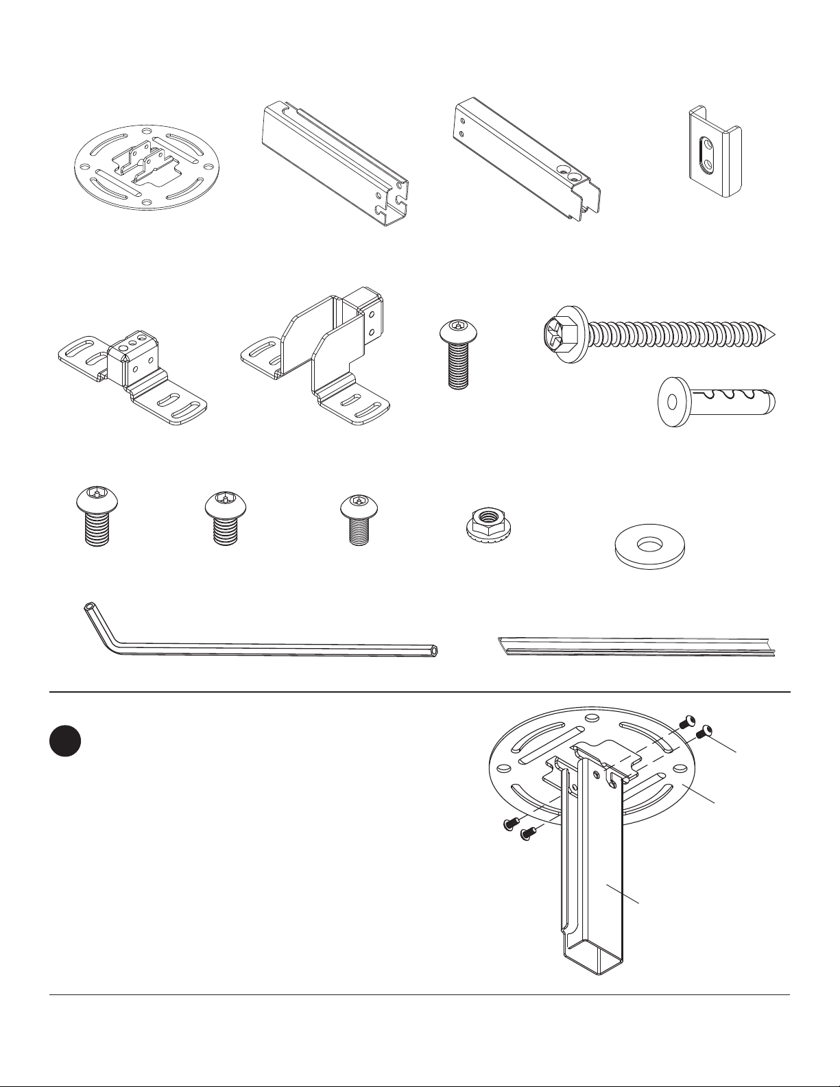
Part List Continued
Parts may appear slightly different than illustrated.
A
B
C
H
E
F
G
KL MN
D
J
O
P
Install Outer Channel to Ceiling Plate
Attach outer channel (B) to ceiling plate (A) using
1
four M6 x 10 mm socket pin screws (L) as shown.
Tighten screws with security wrench (P).
Visit the Peerless Web Site at www.peerlessmounts.com
4 of 11
Q
L
A
B
ISSUED: 1-11-08 SHEET #: 055-9495-2 10-16-08
For customer care call 1-800-865-2112 or 708-865-8870.
Page 5

Installation to Wood Joist Ceilings or Wood Stud Walls
WARNING
• Installer must verify that the supporting surface will safely support the combined load of the equipment and all attached
hardware and components.
• Tighten wood screws so that ceiling/wall plate is firmly attached, but do not overtighten. Overtightening can damage
the screws, greatly reducing their holding power.
• Never tighten in excess of 80 in. • lb (9 N.M.).
• Make sure that mounting screws are anchored into the center of the stud or joist. The use of an "edge to edge" stud
finder is highly recommended.
• Hardware provided is for attachment of mount through standard thickness drywall or plaster into wood studs or joists.
Installers are responsible to provide hardware for other types of mounting situations (not UL approved).
NOTE: Wall installation with models EXC, EXC-S and EXC-W is not available.
2
Use a stud finder to locate the edges of the stud or joist. Use of an edge-to-edge stud finder is highly
recommended. Based on its edges, draw a vertical line down the stud's or joist’s center . Place ceiling/wall plate (A)
on wall or ceiling as a template, making sure that the two mounting slots are on the centerline.
For ceiling installation: Opening on outer channel (B) indicates front of mount. Use the correct mounting slots on
the ceiling/wall plate depending on ceiling joist orientation as shown in figure 2.1 and figure 2.2. Mounting slots on
ceiling plate allow for 45° (±22.5) of rotation before securing to joist.
For wall installation: Opening on outer channel (B) indicates top of mount.
Mark the center of the two mounting holes. Drill two 5/32" (4 mm) dia. holes 2-1/2" (65 mm) deep. Secure
ceiling/wall plate (A) to wood stud or joist using two #14 x 2-1/2" wood screws (H) and two flat washers (O)
as shown.
Skip to step 3
fig. 2.1
A
B
O
H
CEILING INST ALLATION
WOOD
JOIST
A
MOUNTING
SLOTS ALLOW
FOR ROT ATION
BEFORE
SECURING TO
JOIST
OPENING ON OUTER CHANNEL (B)
INDICA TES FRONT OF MOUNT
O
H
fig. 2.2
B
WALL INST ALLA TION
(EXCEPT FOR EXC MODELS)
fig. 2.3
OPENING ON OUTER
CHANNEL (B) INDICA TES
TOP OF MOUNT
B
H
WOOD
STUD
A
O
Visit the Peerless Web Site at www.peerlessmounts.com
5 of 11
ISSUED: 1-11-08 SHEET #: 055-9495-2 10-16-08
For customer care call 1-800-865-2112 or 708-865-8870.
Page 6

Installation to Concrete Ceilings or Concrete/Cinder Block Walls
WARNING
• When installing Peerless wall mounts on cinder block, verify that you have a minimum of 1-3/8" of actual concrete
thickness in the hole to be used for the concrete anchors. Do not drill into mortar joints! Be sure to mount in a solid
part of the block, generally 1" minimum from the side of the block. Cinder block must meet ASTM C-90 specifications.
It is suggested that a standard electric drill on slow setting is used to drill the hole instead of a hammer drill to avoid
breaking out the back of the hole when entering a void or cavity .
• Concrete must be 2000 psi density minimum. Lighter density concrete may not hold concrete anchor .
• Installer must verify that the supporting surface will safely support the combined load of the equipment and all attached
hardware and components.
NOTE: Wall installation with models EXC, EXC-S
2
and EXC-W is not available.
Place ceiling/wall plate (A) on ceiling or wall as a
template. Note: Place ceiling/wall plate according
to position of opening in outer channel (B) as shown
in figure 2.4. or figure 2.5. Drill two 1/4" (6 mm) dia.
holes to a minimum depth of 2.5" (64 mm). Attach
ceiling/wall plate (A) using two concrete anchors (J),
two #14 x 2.5" wood screws (H) and two washers (O)
as shown in figure 2.6. Tighten wood screws (H) until
ceiling/wall plate (A) is firmly attached.
WARNING
• Tighten wood screws firmly , but do not overtighten.
Overtightening can damage the screws, greatly
reducing their holding power.
• Never tighten in excess of 80 in • lb (9 N.M.).
WARNING
• Always attach concrete expansion anchors directly to
load-bearing concrete.
• Never attach concrete expansion anchors to concrete
covered with plaster, drywall, or other finishing material. If mounting to concrete surfaces covered with a
finishing surface is unavoidable, the finishing surface
must be counterbored as shown below. Be sure
concrete anchors do not pull away from concrete
when tightening screws. If plaster/drywall is thicker
than 5/8" (16 mm), custom fasteners must be supplied by installer (not UL approved).
INCORRECT
CORRECT
CEILING
INST ALLATION
fig. 2.4
CONCRETE
CEILING
OPENING ON OUTER
CHANNEL (B) INDICA TES
FRONT OF MOUNT
WALL INST ALLA TION
(EXCEPT FOR
EXC MODELS)
CONCRETE
WALL
fig. 2.5
OPENING ON OUTER
CHANNEL (B)
INDICATES T OP OF
MOUNT
fig.
1
2.6
Drill holes and insert anchors (J).
2
Place plate (A) over anchors (J) and secure with washers (O)
and screws (H).
H
H
O
O
J
A
O
H
B
CINDER
BLOCK
WALL
JBA
concrete
surface
J
A
J
A
plaster/
CUT AW A Y VIEW
Visit the Peerless Web Site at www.peerlessmounts.com
dry wall
concrete
A
plaster/
dry wall
concrete
6 of 11
3
Tighten all fasteners.
ISSUED: 1-11-08 SHEET #: 055-9495-2 10-16-08
For customer care call 1-800-865-2112 or 708-865-8870.
Page 7

Installing Inner Channel and Routing Cables
Note: Be certain holes on inner channel (C) face in the same direction of opening on outer channel (B).
3
Note: Cables must be removed from projector before routing through channels. If cables are not removable from
projector, routing through channels is not an option.
Guide projector cables into openings in channels then insert inner channel (C) into outer channel (B) as shown in
figure 3.1 or 3.3.
Position inner channel (C) to the desired extended position and secure using two M6 x 12 mm socket pin
screws (K) through clamp plate (D) and into inner channel (C) as shown in figure 3.2 or 3.4.
CEILING INST ALLA TION
fig. 3.1
OPENING
HOLES
GUIDE
CABLES IN
CHANNELS
C
B
K
D
fig. 3.2
B
C
WALL INST ALLA TION
(EXCEPT FOR EXC MODELS)
fig. 3.3
HOLES
OPENING
C
B
C
fig. 3.4
B
K
D
Visit the Peerless Web Site at www.peerlessmounts.com
7 of 11
ISSUED: 1-11-08 SHEET #: 055-9495-2 10-16-08
For customer care call 1-800-865-2112 or 708-865-8870.
Page 8

Installing Projector Mount
Installing PRG projector mount with ceiling installation: Attach vertical mounting plate (E) to PRG projector
4
mount (not included) using two M5 x 16 mm socket pin screws (G), four flat washers (O) and two locknuts (N) as
shown in figure 4.1.
Installing PRG projector mount with wall installation: Position PRG projector mount (not included) to the
orientation shown in figure 4.2 and attach to horizontal mounting plate (F) using two M5 x 16 mm socket pin
screws (G), four flat washers (O) and two locknuts (N).
CEILING INST ALLATION
fig. 4.1
PRG PROJECTOR
MOUNT (NOT
INCLUDED)
ARROW
INDICATES
FRONT OF
MOUNT
E
G
O
O
WALL INST ALLA TION
(EXCEPT FOR EXC MODELS)
F
fig. 4.2
PRG PROJECTOR
MOUNT (NOT
INCLUDED)
ARROW
INDICATES
FRONT OF
MOUNT
N
Installing PRS projector mount with wall installation: Position PRS projector mount (not included) to the
orientation shown in figure 4.3 and attach to horizontal mounting plate (F) using two M5 x 16 mm socket pin
screws (G), four flat washers (O) and two locknuts (N).
Installing PRS projector mount with ceiling installation: Attach vertical mounting plate (E) to PRS projector
mount (not included) using two M5 x 16 mm socket pin screws (G), four flat washers (O) and two locknuts (N) as
shown in figure 4.4.
G
O
O
N
Note: Placing washer (O) and nut (N) combination on inside of PRG or PRS projector mount (not included) first while
attaching mounting bracket (E or F) can make installation easier as shown in figure 4.5.
WALL INST ALLA TION
(EXCEPT FOR EXC MODELS)
fig. 4.3
PRS PROJECTOR MOUNT
(NOT INCLUDED)
HOLE INDICATES
FRONT OF MOUNT
G
O
O
fig. 4.5
PRS PROJECTOR MOUNT
(NOT INCLUDED)
Visit the Peerless Web Site at www.peerlessmounts.com
F
N
CEILING INST ALLA TION
fig. 4.4
PRS PROJECTOR MOUNT
(NOT INCLUDED)
HOLE INDICATES
FRONT OF MOUNT
8 of 11
For customer care call 1-800-865-2112 or 708-865-8870.
G
O
E
O
N
PLACE WASHER (O) AND
NUT (N) COMBINA TION
FIRST
N
O
ISSUED: 1-11-08 SHEET #: 055-9495-2 10-16-08
Page 9
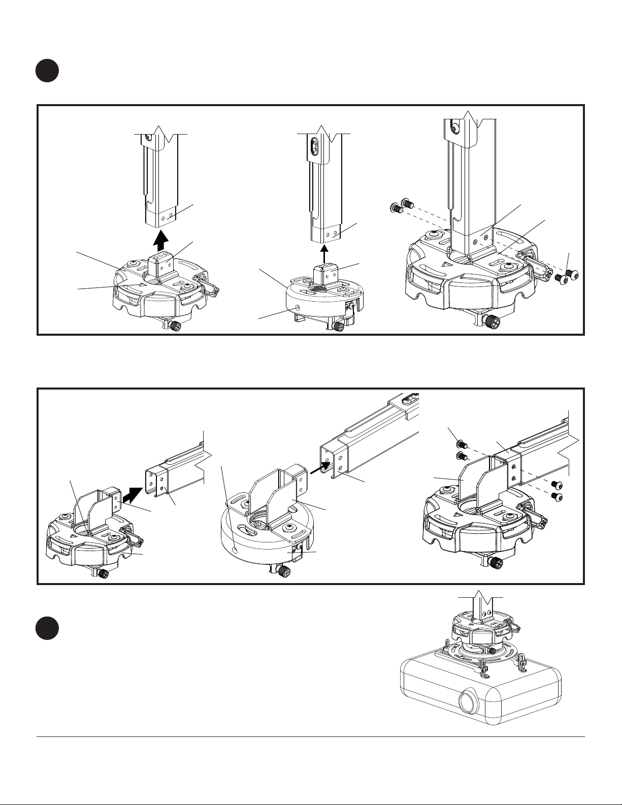
Installing Projector Mount (continued)
Ceiling installation: Insert vertical mounting plate (E) into inner channel (C) with projector mount in the correct
5
orientation shown in figure 5.1 or 5.2. Secure vertical mounting plate to inner channel using four socket pin
screws (M) as shown in figure 5.3.
CEILING INST ALLA TION
fig. 5.1
fig. 5.2
C
PRG PROJECTOR
MOUNT (NOT
INCLUDED)
ARROW
INDICATES
FRONT OF
MOUNT
Wall installation: Insert horizontal mounting plate (F) into inner channel (C) as shown in figure 5.4 or 5.5. Secure
horizontal mounting plate to inner channel using four socket pin screws (M) as shown in figure 5.6.
WALL INST ALLA TION
(EXCEPT FOR EXC MODELS)
E
fig. 5.4
ARROW
INDICATES
FRONT OF
MOUNT
PRS PROJECTOR
MOUNT (NOT
INCLUDED)
HOLE
INDICATES
FRONT OF
MOUNT
fig. 5.5
HOLE INDICATES
FRONT OF MOUNT
C
E
C
fig. 5.3
C
fig. 5.6
M
C
F
E
M
C
F
PRG PROJECTOR
MOUNT (NOT
INCLUDED)
Installing Projector
Refer to instruction manual included with your projector
6
mount for installing projector.
NOTE: Refer to instruction manual included with your
projector mount for max load capacity of your projector
mount.
Visit the Peerless Web Site at www.peerlessmounts.com
F
PRS PROJECTOR
MOUNT (NOT
INCLUDED)
Shown with PRG
projector mount and
projector (not included)
9 of 11
ISSUED: 1-11-08 SHEET #: 055-9495-2 10-16-08
For customer care call 1-800-865-2112 or 708-865-8870.
Page 10
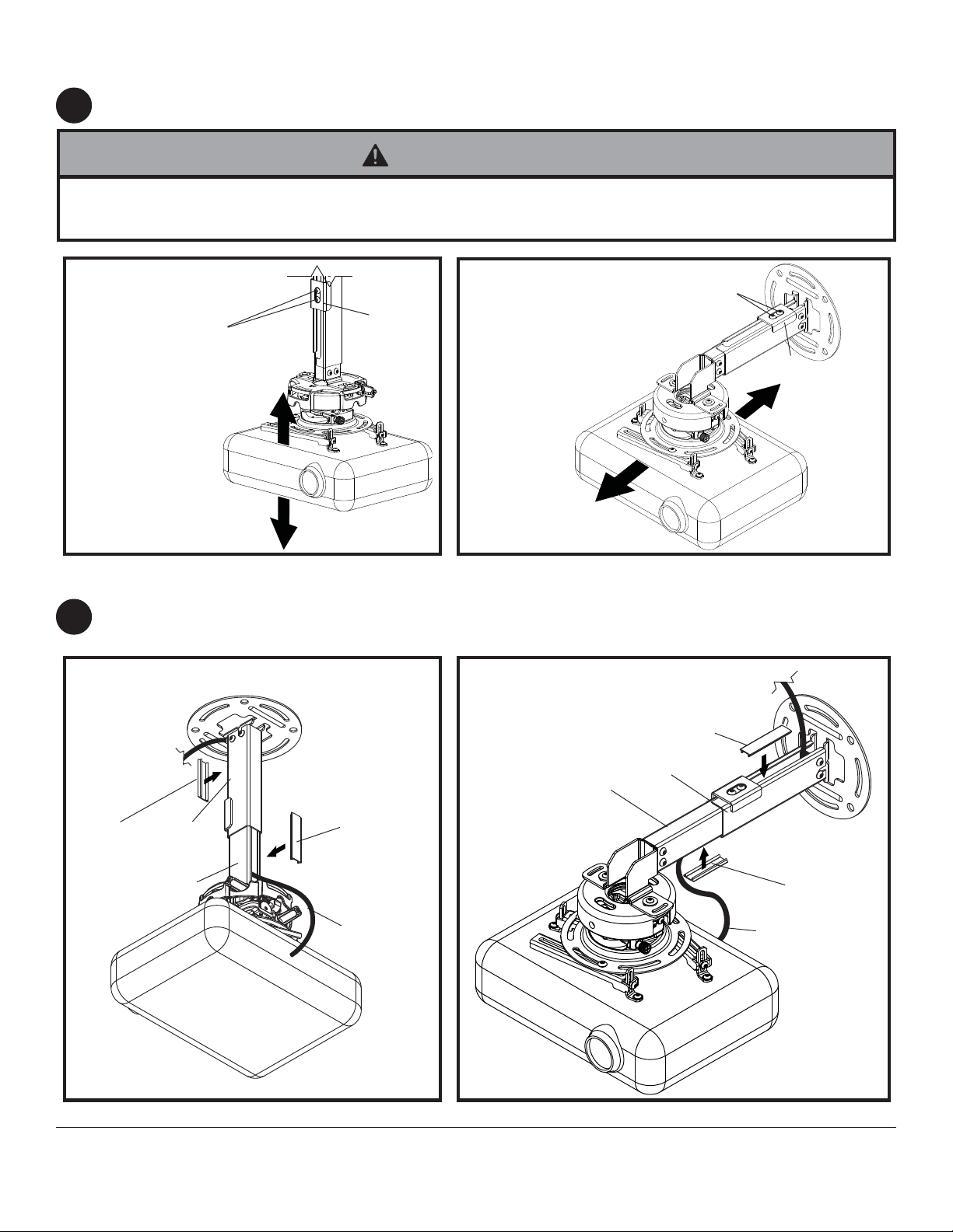
Adjusting Mount Extension
While supporting the weight of the projector, loosen clamp plate screws half a turn and position projector to the
7
desired extended position. Retighten clamp plate screws securely.
WARNING
• On ceiling installations, clamp plate adjustment screws support weight of projector when fully tightened. Weight of the
projector will need to be supported if clamp plate screws are loosened.
CEILING INST ALLA TION
CLAMP PLA TE
SCREWS
D
WALL INST ALLA TION
(EXCEPT FOR EXC MODELS)
CLAMP PLA TE
SCREWS
Install Cable Covers
Cut cable covers (Q) to the length of inner channel (C) and outer channel (B) openings, leaving space for cables if
8
routed through channels. Snap cable covers (Q) into openings as shown.
CEILING INST ALLA TION
WALL INST ALLA TION
(EXCEPT FOR EXC MODELS)
Q
CUT TO
LENGTH OF
OPENING
D
Q
CUT TO
Q
CUT TO
LENGTH OF
OPENING
Visit the Peerless Web Site at www.peerlessmounts.com
B
C
LENGTH OF
OPENING
CABLES
10 of 11
C
B
Q
CUT TO
LENGTH OF
OPENING
CABLES
ISSUED: 1-11-08 SHEET #: 055-9495-2 10-16-08
For customer care call 1-800-865-2112 or 708-865-8870.
Page 11

Projector Alignment
For PRG swivel adjustment: Loosen two screws indicated in figure 9.1 half a turn using allen wrench (P) to allow
9
for adjusting swivel. Align projector to the desired swivel position and fully tighten screws indicated.
For PRS swivel adjustment: Loosen two screws indicated in figure 9.1 half a turn using allen wrench (P) to allow
for adjusting swivel. Align projector to the desired swivel position and fully tighten screws indicated.
T o adjust tilt and roll, refer to instruction included with projector mount.
WARNING
• Do not loosen adjustment screws to the point they become disengaged from the mount. Weight of the projector should
be supported in case of accidental disengagement.
fig. 9.1
SWIVEL ADJUSTMENT WITH PRG
SCREWS FOR SWIVEL
ADJUSTMENT
fig. 9.2
SWIVEL ADJUSTMENT WITH PRS
SCREWS FOR SWIVEL
ADJUSTMENT
Visit the Peerless Web Site at www.peerlessmounts.com
20° (±10°) SWIVEL
SWIVEL ADJUSTMENT
TOP VIEW
11 of 11
All other brand and product names are trademarks or registered trademarks of their respective owners.
ISSUED: 1-11-08 SHEET #: 055-9495-2 10-16-08
For customer care call 1-800-865-2112 or 708-865-8870.
© 2008, Peerless Industries, Inc. All rights reserved.
 Loading...