

Page 1
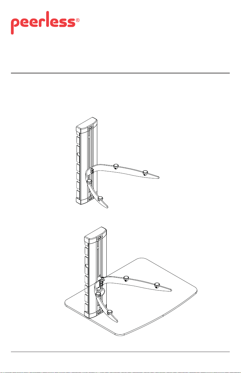
Installation and Assembly:
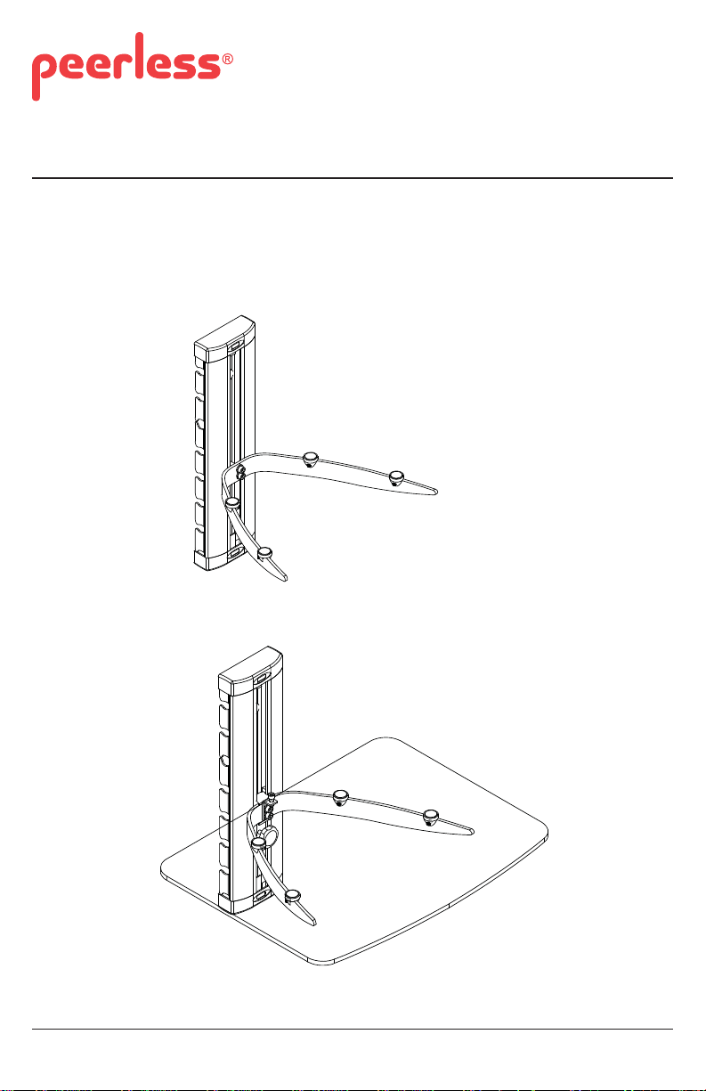
A/V Component Shelf
Models: ACCSH100, ACCSH200, ESHV10, ESHV20
Max Load Capacity: 30 lb (13.6 kg)
ACCSH100, ESHV10
ACCSH200, ESHV20
ISSUED: 01-17-11 SHEET #: 083-9013-1
Page 2
NOTE: Read entire instruction sheet before you start installation and assembly.
WARNING
• Do not begin to install your Peerless product until you have read and understood the instructions
and warnings contained in this Installation Sheet. If you have any questions regarding any of the
instructions or warnings, for US customers please call Peerless customer care at
1-800-865-2112, for all international customers, please contact your local distributor.
• This product should only be installed by someone of good mechanical aptitude, has experience
with basic building construction, and fully understands these instructions.
• Make sure that the supporting surface will safely support the combined load of the equipment and
all attached hardware and components.
• Never exceed the Maximum Load Capacity. See page one.
• If mounting to wood wall studs, make sure that mounting screws are anchored into the center of
the studs. Use of an "edge to edge" stud fi nder is highly recommended.
• Always use an assistant or mechanical lifting equipment to safely lift and position equipment.
• Tighten screws fi rmly, but do not overtighten. Overtightening can damage the items, greatly
reducing their holding power.
• This product is intended for indoor use only. Use of this product outdoors could lead to product
failure and personal injury.
• This product was designed to be installed on the following wall construction only;
WALL CONSTRUCTION HARDWARE REQUIRED
• Wood Stud Included
• Wood Beam Included
• Solid Concrete Included
• Metal Stud Do not attach except with Peerless Metal Stud Accessory
Kit; ACC215. Contact Customer Service for Peerless
metal stud accessory kit.
• Brick Contact Qualifi ed Professional
• Other or unsure? Contact Qualifi ed Professional
Tools Needed for Assembly
• stud fi nder ("edge to edge" stud fi nder is recommended)
• phillips screwdriver
• drill
• 5/16" (8mm) bit for concrete surface
• 1/8" (3mm) bit for wood studs
• level
Table of Contents
Parts List................................................................................................................................................3
Installation to Wood Stud Wall...............................................................................................................4
Installation to Solid Concrete or Cinder Block........................................................................................5
Cable Management................................................................................................................................8
2 of 27
ISSUED: 01-17-11 SHEET #: 083-9013-1
Page 3
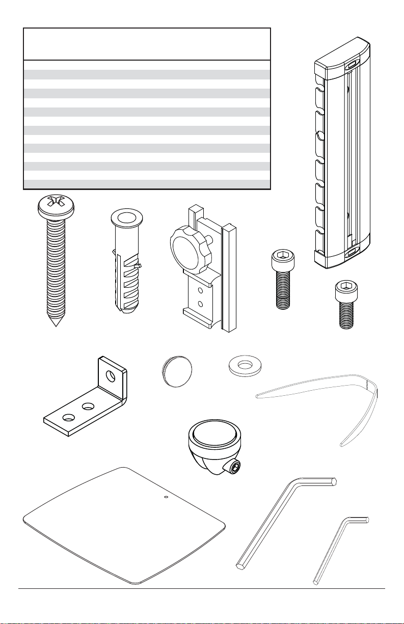
Before you start check the parts list to insure all of the parts shown are included.
0
0
Parts List
Description
A column
B M5 X 44mm wood screw
C wall anchor
D shelf attachment clamp
E M5 X 18mm socket cap screw
F M5 X 12mm socket cap screw
G glass support bracket
H screw cover 2
I M5 washer
J shelf bracket
K glass shelf
L support clip 4 4
M 4mm allen wrench
N 2.5mm allen wrench
ACCSH100/ESHV1
Qty.
11
22
22
11
22
—1
—1
23
11
—1
11
11
ACCSH200/ESHV2
Qty.
A
2
B
C
D
E
F
G
H
I
J
L
K
M
N
3 of 27
ISSUED: 01-17-11 SHEET #: 083-9013-1
Page 4
Installation to Single Wood Stud Wall
WARNING
• Installer must verify that the supporting surface will safely support the combined load of the
equipment and all attached hardware and components.
• Tighten wood screws so that wall plate is fi rmly attached, but do not overtighten. Overtightening
can damage the screws, greatly reducing their holding power.
• Never tighten in excess of 80 in. • lb (9 N.M.).
• Make sure that mounting screws are anchored into the center of the stud. The use of an "edge to
edge" stud fi nder is highly recommended.
• Hardware provided is for attachment of mount through standard thickness drywall or plaster into
wood studs. Installers are responsible to provide hardware for other types of mounting situations.
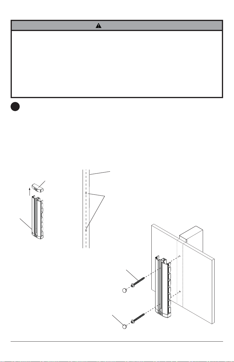
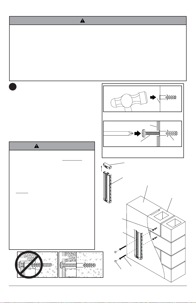
Remove end cap with bubble level from column (A). Column (A) can be mounted to a single
1
stud. Use a stud fi nder to locate the edges of the stud. Use of an edge-to-edge stud fi nder is
highly recommended. Based on their edges, draw a vertical line down the stud’s center. Place
column (A) on wall as a template. Level column and mark the center of the two mounting holes
as shown in fi gure 1.1. Make sure that the center mounting holes are on the stud center lines.
Drill two mounting holes .12" (3mm) dia. by 2" (51mm) deep. Secure column (A) with two
M5 X 44mm wood screws (B) as shown in fi gure 1.2.
Tighten fasteners then cover M5 X 44mm wood screws (B) with screw covers (H).
Skip to step 3
STUD
END CAP
A
fi g. 1.1
DRILL .12" DIA
HOLES
B
H
4 of 27
fi g. 1.2
ISSUED: 01-17-11 SHEET #: 083-9013-1
Page 5
Installation To Solid Concrete or Cinder Block
WARNING
• When installing Peerless wall mounts on cinder block, verify that you have a minimum of 1-3/8"
(35 mm) of actual concrete thickness in the hole to be used for the concrete anchors. Do not drill
into mortar joints! Be sure to mount in a solid part of the block, generally 1" (25 mm) minimum
from the side of the block. Cinder block must meet ASTM C-90 specifi cations. It is suggested
that a standard electric drill on slow setting is used to drill the hole instead of a hammer drill to
avoid breaking out the back of the hole when entering a void or cavity.
• Concrete must be 2000 psi density minimum. Lighter density concrete may not hold concrete
anchor.
• Installer must verify that the supporting surface will safely support the combined load of the
equipment and all attached hardware and components.
Remove end cap with bubble level from
1
column (A) as shown in fi gure 1.1. Make sure
that column (A) is level, use it as a template
to mark two mounting holes. Drill two 5/16" (8
mm) dia. holes to a minimum depth of 2"
(51 mm). Insert anchors (C) in holes fl ush with
wall as shown. Place column (A) over anchors
and secure with two M5 X 44mm wood screws
(B).
Tighten fasteners then cover M5 X 44mm
wood screws (B) with screw covers (H) as
shown in fi gure 1.2.
WARNING
• Tighten screws so that column is
fi rmly attached, but do not overtighten.
Overtightening can damage screws, greatly
reducing their holding power.
• Never tighten in excess of 80 in. • lb (9
N.M.).
• Always attach concrete expansion anchors
directly to load-bearing concrete.
• Never attach concrete expansion anchors
to concrete covered with plaster, drywall,
or other fi nishing material. If mounting to
concrete surfaces covered with a fi nishing
surface is unavoidable, the fi nishing
surface must be counter bored as shown
below. Be sure concrete anchors do not
pull away from concrete when tightening
screws. If plaster/drywall is thicker than
5/8" (16 mm), custom fasteners must be
supplied by installer.
1
Drill holes and insert anchors (C).
2
A
B
Place column (A) over anchors (C) and secure
with screws (B). Tighten all fasteners.
END CAP
A
CONCRETE
fi g. 1.1
C
A
concrete
surface
C
C
CINDER BLOCK
column
plaster/
dry wall
CUTAWAY VIEW
INCORRECT CORRECT
concrete
column
plaster/
dry wall
concrete
5 of 27
B
H
fi g. 1.2
ISSUED: 01-17-11 SHEET #: 083-9013-1
Page 6
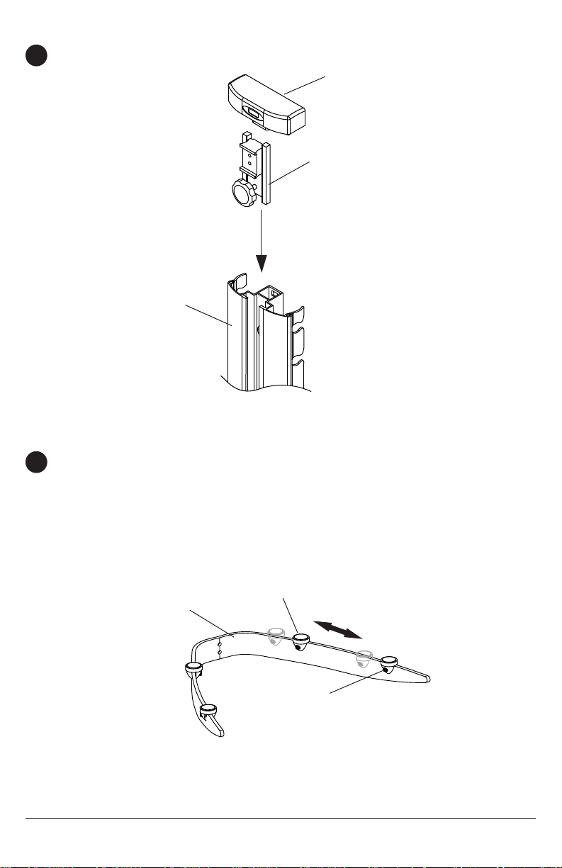
Installing Shelf to Column
Slide shelf attachment clamp (D) into column (A) and reattach end cap onto column (A) as
2
shown in fi gure 3.1.
END CAP
D
A
fi g. 3.1
Attach support clips (L) to shelf bracket (J) and slide to desired position as shown in fi gure 4.1.
3
Securely tighten all set screws using the 2.5 mm allen wrench (N). Do not overtighten screws.
NOTE: Set screws may already be attached to support clips.
For ACCSH100 and ESHV10 models, continue to step 5. For ACCSH200 and ESHV20 models,
skip to step 6.
L
J
SET SCREW
fi g. 4.1
6 of 27
ISSUED: 01-17-11 SHEET #: 083-9013-1
Page 7
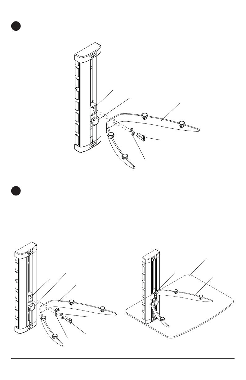
ACCSH100 and ESHV10 Models
Attach shelf bracket (J) to shelf attachment clamp (D) using two M5 x 18mm screws (E) and
4
washers (I) shown in fi gure 5.1 using 4mm allen wrench (M). Adjust the level of the shelf bracket
(J) to desired height then tighten knob to secure.
D
KNOB
J
E
fi g. 5.1
I
ACCSH200 and ESHV20 Models
Attach shelf bracket (J) and glass support bracket (G) to shelf attachment clamp (D) using two
5
M5 x 18mm screws (E) and washers (I) shown in fi gure 6.1 using 4mm allen wrench (M). Adjust
the level of the shelf bracket (J) to desired height then tighten knob to secure.
Place glass shelf (K) onto shelf bracket (J) and secure with M5 x 12mm screw (F) as shown in
fi gure 6.2 using 2.5mm allen wrench (N).
NOTE: Overtightening the screws may cause damage to glass shelf (K).
KNOB
F
D
J
I
E
G
fi g. 6.1
7 of 27
fi g. 6.2
ISSUED: 01-17-11 SHEET #: 083-9013-1
K
J
Page 8
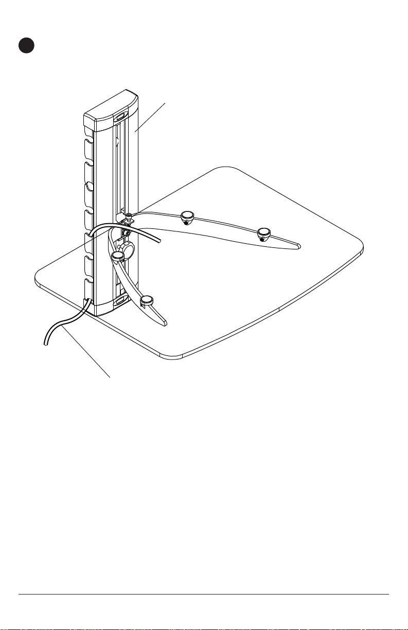
Cable Management
This mount includes a cable management function, where cables can be routed along the side
6
interior of the column (A).
NOTE: For best system performance, route the power cables separately from the signal cables.
A
Peerless Industries, Inc.
2300 White Oak Circle
Aurora, IL 60502
www.peerlessconsumer.com
CABLES
8 of 27
All other brand and product names are trademarks or registered trademarks of their respective owners.
ISSUED: 01-17-11 SHEET #: 083-9013-1
© 2011, Peerless Industries, Inc. All rights reserved.
Page 9
Instrucciones para la instalación y el ensamblaje:
A/V Período de componentes
Modelos: ACCSH100, ACCSH200, ESHV10, ESHV20
Capacidad máxima de soportar carga:
30 lb (13.6 kg)
ACCSH100, ESHV10
ACCSH200, ESHV20
PUBLICADO: 01-17-11 HOJA #: 083-9013-1
Page 10

NOTA: Lea toda la hoja de instrucciones antes de iniciar la instalación y el montaje.
ADVERTENCIA
• No comience a instalar su producto de Peerless hasta haber leído y entendido las instruccio-
nes y las advertencias contenidas en la Hoja de Instalación. Si tiene alguna pregunta acerca
de cualquiera de las instrucciones o las advertencias, por favor, llame a Servicio al Cliente
de Peerless al 1-800-865-2112 si está en EE. UU. Si es un cliente internacional, por favor,
comuníquese con su distribuidor local.
• Este producto sólo debe ser instalado por una persona que tenga una buena aptitud mecánica, que tenga experiencia en construcción básica de edifi cios y que entienda estas instruccio-
nes en su totalidad.
• Asegúrese de que la superfi cie de apoyo sostendrá, con seguridad, la carga combinada del
equipo y todos los fi jadores y componentes.
• Nunca sobrepase la capacidad máxima de soportar carga.
• Si va a instalar el producto en una pared con montantes de madera, asegúrese de que los
tornillos de montaje estén anclados en el centro de los montantes. Se recomienda utilizar un
localizador de montantes de "borde a borde".
• Siempre cuente con la ayuda de un asistente o utilice un equipo mecánico de izar para levantar y colocar el equipo con más seguridad.
• Apriete los tornillos con fi rmeza, pero no en exceso. Apretarlos en exceso puede dañar los
artículos y puede disminuir signifi cativamente su fuerza de fi jación.
• Este producto está diseñado para uso en interiores solamente. Utilizar este producto en exteriores podría causar fallas del producto y lesiones a individuos.
• Este producto fue diseñado para ser instalado en paredes con la siguiente construcción solamente:
CONSTRUCCIÓN DE LA PARED ACCESORIOS NECESARIOS
• Montante de madera Incluido
• Viga de madera Incluido
• Concreto macizo Incluido
• Bloque de hormigón de escorias Incluido
• Montante de metal No lo instale excepto con el juego de
accesorios de Peerless para
montantes de metal; ACC215
• Ladrillo Comuníquese con un profesional califi cado
• ¿Otra superfi cie o no está seguro? Comuníquese con un profesional califi cado
Vea la página 9.
Español
Herramientas necesarias para el ensamblaje
• localizador de montantes (se recomienda uno de "borde a borde")
• destornillador phillips
• taladro
• broca de 5/16" (8 mm) para paredes de concreto y de bloque de hormigón de escorias
• broca de 1/8" (3 mm) para paredes con montantes de madera
• nivel
Tabla de contenido
Lista de piezas.....................................................................................................................................11
Instalación en una pared con montante de madera ............................................................................12
Instalación en una pared de concreto macizo o de bloques de hormigón de escorias........................13
Accesorios ...........................................................................................................................................16
10 de 27 PUBLICADO: 01-17-11 HOJA #: 083-9013-1
Page 11

Antes de comenzar, coteje la lista de piezas para asegurarse de que se han incluido todas las piezas.
0
0
Lista de piezas
Descripción
A columna
B tornillo para madera M5 X 44mm
C anclaje para concreto
D Deslice la abrazadera para fijar la repisa
E M5 X 18mm tornillos de cabeza hueca
F M5 X 12mm tornillos de cabeza hueca
G vidrio soporte
H tornillo de la tapa 2
I M5 lavadora
J soporte de estante
K estante de vidrio
L apoyo clip 4 4
M Llave Allen de 4 mm
N Llave Allen de 2.5 mm
ACCSH100/ESHV1
Cant.
11
22
22
11
22
—1
—1
23
11
—1
11
11
ACCSH200/ESHV2
Cant.
A
2
Español
B
C
D
E
F
G
H
I
J
L
K
M
N
11 de 27 PUBLICADO: 01-17-11 HOJA #: 083-9013-1
Page 12

Español
Instalación en una pared con montantes
ADVERTENCIA
• El instalador debe verifi car que la superfi cie de apoyo sea capaz de soportar fi rmemente la
carga combinada del equipo y todos los herrajes y componentes.
• Apriete los tornillos para madera de tal modo que la placa de apoyo quede fi rmemente sujeta,
pero no apriete en exceso. El apriete excesivo puede dañar los tornillos, reduciendo enormemente su fuerza de fi jación.
• Nunca apriete más de 80 pulg-lb (9 N•m).
• Asegúrese de que los tornillos de montaje queden bien fi jos en el centro del montante. Se reco-
mienda usar un localizador de montantes de "borde a borde".
• Los herrajes suministrados son para fi jar el soporte a través de tabique de yeso-cartón o yeso
de espesor estándar a los montantes de madera. Los instaladores son responsables de suministrar los herrajes para otros tipos de situaciones de montaje.
Retire la tapa de extremo con nivel de burbuja de la columna (A). La columna (A) se puede
1
instalar en un solo montante. Utilice un localizador de montantes para localizar los bordes del
montante. Se recomienda utilizar un localizador de montantes de "borde a borde". Tomando los
bordes como punto de referencia, trace una línea vertical por el centro del montante. Coloque
la columna (A) contra la pared para utilizarla como plantilla. Nivele la columna y marque el
centro de los dos agujeros de montaje, como se muestra en la fi gura 1.1. Asegúrese de que los
agujeros de montaje centrales estén sobre las líneas que trazó por el centro de los montantes.
Taladre dos agujeros de montaje de .12" (3mm) de diámetro por 2" (51mm) de profundidad. Fije
la columna (A) utilizando dos tornillos para madera de
M5 x 44mm (B).
Ajuste todos los sujetadores, cubra los tornillos para madera de M5 x 44mm (C) con las cubierta
de goma (H), como se muestra en la fi gura 1.2.
Pase al paso 3.
CUBIERTA DE LOS
EXTREMOS
MONTANTE
A
HOYOS DE
DIAMETRO .12"
B
fi g. 1.1
H
fi g. 1.2
12 de 27 PUBLICADO: 01-17-11 HOJA #: 083-9013-1
Page 13

Español
Instalación en una pared de concreto macizo o de
bloques de hormigón de escorias
ADVERTENCIA
• Cuando instale soportes de pared Peerless en bloques de hormigón de escorias, verifi que que tengan un
mínimo de 1-3/8" (35 mm) de superfi cie efectiva de concreto en el agujero que va a utilizar para los anclajes
de concreto. ¡No perfore en las juntas de mortero! Asegúrese de instalar el soporte en una parte sólida del
bloque, generalmente a un mínimo de 1" (25 mm) del costado del bloque. El bloque de hormigón de escorias
debe ser de conformidad con las especifi caciones C-90 de ASTM. Se sugiere taladrar el agujero con un
taladro eléctrico normal en velocidad lenta en vez de un taladro percutor para evitar romper la parte trasera
del agujero al entrar en un espacio o cavidad.
• El concreto debe tener una densidad mínima de 2000 psi. Un concreto menos denso podría no ser capaz de
sujetar el anclaje para concreto.
• El instalador debe verifi car que la superfi cie de apoyo sea capaz de soportar fi rmemente la carga combinada
del equipo y todos los herrajes y componentes.
Retire la tapa de extremo con nivel de burbuja
1
de la columna (A). Asegúrese de que la
columna (A) esté nivelada y utilícela como
plantilla para marcar dos agujeros de montaje.
Taladre dos agujeros de 5/16" (8 mm) de
diámetro a una profundidad mínima de 2" (51
mm). Inserte los anclajes (C) en los agujeros
a ras con la pared, como se muestra. Coloque
la columna (A) sobre los anclajes y fíjela con
dos tornillos de M5 x 44mm (B).
Ajuste todos los sujetadores, cubra los
tornillos para madera de M5 x 44mm (B) con
las cubierta de goma (H), como se muestra en
la fi gura 1.2.
ADVERTENCIA
• Apriete los tornillos de tal modo que la placa de
apoyo quede fi rmemente sujeta, pero no los apriete
en exceso. El apriete excesivo puede dañar los tornillos, reduciendo enormemente su fuerza de fi jación.
• Nunca apriete más de 80 pulg-lb (9 N•m).
• Siempre fi je los anclajes de expansión directamente
al concreto que soporta carga.
• Nunca fi je los anclajes de expansión a una pared de
concreto recubierta con yeso, tabiques de yesocartón u otro material de acabado. Si el montaje a
superfi cies de concreto recubiertas con una superfi cie
de acabado es inevitable, será necesario escariar el
acabado, como se muestra más abajo. Asegúrese
de que los anclajes de concreto no se alejen del concreto al apretar los tornillos. Si el grosor de la pared
de yeso/tabique de yeso-cartón es mayor que
5/8" (16 mm), el instalador deberá suministrar fi jacio-
nes especiales.
INCORRECTO CORRECTO
columna
concreto
columna
concreto
1
Perfore los agujeros y después inserte los
anclajes (C).
2
A
B
Coloque la columna (A) sobre los anclajes
(C) y fíjela con los tornillos (B). Apriete todas las
fi jaciones.
fi g. 1.1
CUBIERTA DE
LOS EXTREMOS
A
CONCRETO
MACIZO
C
A
superfi cie de
concreto
C
C
BLOQUE DE
HORMIGÓN
DE ESCORIAS
VISTA EN CORTE
yeso / tabique de yeso-cartón
B
H
fi g. 1.2
13 de 27 PUBLICADO: 01-17-11 HOJA #: 083-9013-1
Page 14

Instalar la Repisa en la Columna
Deslice la abrazadera para fi jar la repisa (D) en la columna (A) y vuelva a colocar la cubierta del
2
extremo de la columna, como se muestra en la fi gura 3.1.
CUBIERTA DE
LOS EXTREMOS
D
A
fi g. 3.1
Español
Fije los clips para sujetar cristal (L) al soporte para repisas (J) y deslícelo hasta la posición
3
deseada como se muestra en la fi gura 4.1. Apriete, con fi rmeza, todos los tornillos de fi jación
utilizando una llave allen de 2.5 mm (N). no apriete demasiado los tornillos
NOTA: Es posible que los tornillos de fi jación ya estén fi jados a los clips para sujetar cristal.
Para los modelos ACCSH100 y ESHV10, continúe con el paso 5. Para los modelos ACCSH200 y
ESHV20, vaya al paso 6.
L
J
EL TORNILLO
DE AJUSTE
fi g. 4.1
14 de 27 PUBLICADO: 01-17-11 HOJA #: 083-9013-1
Page 15

ACCSH100 y modelos ESHV10
Fije el soporte de estante (J) a la abrazadera para fi jar la repisa (D) usando dos tornillos de
4
M5 x 18 mm (E) y las arandelas (I) muestra en la fi gura 5.1 utilizando una llave allen de
4 mm (M). Ajuste el nivel del soporte de estante (J) a la altura deseada y apriete la perilla para
asegurarla.
D
PERILLA
J
E
Español
fi g. 5.1
I
ACCSH200 y modelos ESHV20
Fije el soporte de estante (J) y el vidrio soporte (G) a la abrazadera para fi jar la repisa (D)
5
usando dos tornillos de M5 x 18 mm (E) y las arandelas (I) muestra en la fi gura 6.1 utilizando
una llave allen de 4 mm (M). Ajuste el nivel del soporte de estante (J) a la altura deseada y
apriete la perilla para asegurarla.
Coloque la repisa de cristal (K) sobre el soporte para repisas (J) y fíjelo con un tornillo de
M5 x 12 mm (F) como se muestra en la fi gura 6.2. utilizando llave allen de 2.5 mm (F).
NOTA: Si se aprieta demasiado los tornillos puede causar daño al estante de vidrio (K).
PERILLA
F
D
J
I
E
G
fi g. 6.1
15 de 27 PUBLICADO: 01-17-11 HOJA #: 083-9013-1
fi g. 6.2
K
J
Page 16

Sistema Para Manejo de Cables
Este soporte incluye un sistema para manejo de cables, que permite pasar los cables por el
6
interior de la columna (A).
NOTA: Para un mejor funcionamiento, acomode los cables de electricidad separados de los
cables de interface.
A
Español
Peerless Industries, Inc.
2300 White Oak Circle
Aurora, IL 60502
www.peerlessconsumer.com
CABLES
16 de 27 PUBLICADO: 01-17-11 HOJA #: 083-9013-1
Cualesquiera otras marcas y nombres de productos son marcas comerciales o registradas de sus respectivos dueños.
© 2011 Peerless Industries, Inc. Todos los derechos reservados.
Page 17

Installation et Montage :
A/V Composante du plateau
modèles: ACCSH100, ACCSH200, ESHV10, ESHV20
Capacité de charge maximale: 30 lb (13.6 kg)
ACCSH100, ESHV10
ACCSH200, ESHV20
PUBLIÉ LE: 01-17-11 FEUILLE No: 083-9013-1
Page 18

REMARQUE: Lisez entièrement la fi che d’instructions avant de commencer l’installation et l’assemblage.
Français
AVERTISSEMENT
• Ne commencez pas à installer votre produit Peerless avant d’avoir lu et assimilé les instructions
et les avertissements contenus dans cette fi che d’installation. Pour toute question concernant les
instructions ou les avertissements, veuillez appeler le service à la clientèle de Peerless au 1-800865-2112; tous les clients internationaux sont priés de contacter leur distributeur local.
• Ce produit doit être installé uniquement par quelqu’un possédant une bonne aptitude à la mécanique, une expérience de la construction immobilière et ayant bien compris ces instructions.
• Assurez-vous que la surface de support puisse soutenir sans danger la charge totale de
l’équipement ainsi que des pièces et composants qui y sont attachés.
• Ne dépassez jamais la capacité de charge maximum. Reportez-vous à la page 19.
• Lors d’une installation sur un mur à montants en bois, assurez-vous que les vis de montage sont
ancrées au centre des montants. L’utilisation d’un localisateur de montants " bord à bord " est
fortement recommandée.
• Pour lever et positionner l’équipement en toute sécurité, faites-vous toujours aider par une autre
personne ou utilisez un dispositif de levage mécanique.
• Serrez fermement les vis, mais sans excès. Un serrage excessif peut endommager les composants et en réduire considérablement la capacité de support.
• Ce produit est conçu uniquement pour un usage intérieur. L’utilisation de ce produit à l’extérieur
peut causer une défaillance du produit et des blessures corporelles.
• Ce produit a été conçu uniquement pour une installation sur les types de murs ci-dessous :
TYPE DE MUR PIÈCES DE FIXATION REQUISES
• Montant en bois Incluses
• Poutre en bois Incluses
• Béton plein Incluses
• Bloc de béton de mâchefer Incluses
• Montant métallique Ne pas installer sur ce type de mur sauf à l’aide
de l’ensemble d’accessoires
Peerless pour montants métalliques; ACC215
• Brique Contacter un professionnel qualifi é
• Autre, ou vous n’êtes pas sûr ? Contacter un professionnel qualifi é
Outils nécessaires au montage
• localisateur de montants (un localisateur de montants " bord à bord " est recommandé)
• tournevis phillips
• perceuse
• foret de 5/16 po (8 mm) pour les murs à block de béton
• foret de 1/8 po (3 mm) pour les murs à montants en bois
• niveau
Table des matières
Liste des pièces ...................................................................................................................................19
Installation sur un mur à montant en bois............................................................................................20
Installation sur du béton plein ou un bloc de béton de mâchefer ........................................................21
Gestion des câbles ..............................................................................................................................24
18 sur 27 PUBLIÉ LE: 01-17-11 FEUILLE No: 083-9013-1
Page 19

Avant de commencer, veillez à ce que toutes les pièces énumérées soient incluses.
0
0
Liste des pièces
Description
A colonne
B M5 X 44mm vis à bois
C ancrage mural
D pince de fixation plateau
E M5 x 18mm Vis à tête cylindrique
F M5 x 12mm Vis à tête cylindrique
G support en verre
H vis de couverture 2
I Rondelle M5
J Rondelle M5
K étagère en verre
L clip de soutien 4 4
M Clé Allen de 4 mm
N Clé Allen de 2.5 mm
ACCSH100/ESHV1
Qté
11
22
22
11
22
—1
—1
23
11
—1
11
11
ACCSH200/ESHV2
Qté
2
A
B
C
D
E
F
Français
G
H
I
J
L
K
M
N
19 sur 27 PUBLIÉ LE: 01-17-11 FEUILLE No: 083-9013-1
Page 20

Français
Installation Sur un Mur à Montants en Bois
AVERTISSEMENT
• L’installateur doit s’assurer que la surface de support pourra soutenir sans danger la charge
combinée de l’équipement, de toute sa visserie et de tous ses composants.
• Serrez les vis à bois de manière que la plaque murale soit fermement fi xée, mais sans excès.
Un serrage excessif peut endommager les vis et en réduire considérablement le pouvoir de
maintien.
• Ne serrez jamais à plus de 9 Nm (80 po-lb).
• Assurez-vous que les vis de montage sont ancrées au centre des montants. L’usage d’un localisateur de montants " bord à bord " est fortement conseillé.
• La visserie est fournie pour fi xer la monture à travers une cloison sèche ou du plâtre
d’épaisseur standard et dans des montants en bois. Il appartient aux installateurs de fournir la
visserie nécessaire pour d’autres types de situations.
Retirer embout avec niveau à bulle de la colonne (A) comme le montre la fi gure 1.1. La
1
colonne (A) peut être installée à un seul montant. Repérez les bords du montant à l’aide d’un
localisateur de montants. L’utilisation d’un localisateur de montants " bord à bord " est fortement
recommandée. Après avoir repéré les bords, tracez une ligne verticale le long du centre du
montant. Posez la colonne (A) sur le mur et utilisez-la comme gabarit. Mettez la colonne à niveau
et marquez le centre des deux trous de fi xation, comme illustré à la fi gure 1.1 Veillez à ce que les
trous de fi xation centraux soient sur la ligne médiane du montant. Percez deux trous de fi xation
de .12 po (43mm) de dia. et de 2 po (51 mm) de profondeur. Fixez la colonne (A) à l'aide de deux
vis à bois no M5 x 44mm (B) comme illustré à la fi gure 1.2.
Serrer les vis M5 puis couvrir X 44mm bois (B) avec cache-vis (H) comme le montre la fi gure 1.2.
Passez à l’étape 3.
A
MONTANTE DE
MADERA
EMBOUT
TROUS .12" PO
fi g. 1.1
B
H
fi g. 1.2
20 sur 27 PUBLIÉ LE: 01-17-11 FEUILLE No: 083-9013-1
Page 21

Installation sur du béton plein ou un bloc de béton de mâchefer
WARNING
• Si vous installez des montures murales Peerless sur un bloc de béton de mâchefer, vérifi ez que vous
disposez d’une épaisseur de béton d’au moins 35 mm (1 3/8 po) dans le trou destiné aux ancrages de béton.
Ne percez pas dans les joints de mortier ! Veillez à effectuer le montage dans une partie pleine du bloc,
généralement à au moins 25 mm (1 po) du côté du bloc. Le bloc de béton de mâchefer doit être conforme
aux spécifi cations de l’ASTM C-90. Pour percer le trou, il est conseillé d’utiliser une perceuse électrique
standard sur un réglage bas au lieu d’un marteau perforateur, afi n d’éviter de briser la partie arrière du trou
lorsque vous pénétrez un vide ou une cavité.
• Le béton doit avoir une densité minimum de 2 000 psi. Un béton de densité moindre risquerait de ne pas
retenir un ancrage de béton.
• Assurez-vous que la surface de support pourra soutenir sans danger la charge combinée de l’équipement,
de toute sa visserie et de tous ses composants.
Retirer embout avec niveau à bulle de la colonne (A)
1
comme le montre la fi gure 1.1. Assurez-vous que
la colonne (A) est de niveau et utilisez-la comme
gabarit pour marquer l’emplacement des deux trous
de fi xation. Percez deux trous de 5/16 po (8 mm) de
dia. à une profondeur minimale de 2 po (51 mm).
Insérez les chevilles d’ancrage (C) dans les trous au
ras du mur comme illustré. Posez la colonne (A) sur
les chevilles d’ancrage et attachez-la à l’aide de deux
vis M5 X 44 mm (B).
Serrer les vis puis couvrir M5 X 44 mm bois (B) avec
cache-vis (H) comme le montre la fi gure 1.2.
1
Percez des trous et insérez les ancrages (C).
2
A
surface en
béton
C
Français
WARNING
• Serrez les vis de manière que la plaque murale
soit fermement fi xée, mais sans excès. Un
serrage excessif peut endommager les vis
et en réduire considérablement le pouvoir de
maintien.
• Ne serrez jamais à plus de 9 Nm (80 po-lb).
• Fixez toujours des ancrages de béton
directement sur du béton porteur.
• Ne fi xez jamais d’ancrages sur du béton
recouvert de plâtre, une cloison sèche ou
autre matériau de fi nition. Si vous ne pouvez
pas éviter d’effectuer le montage sur du béton
recouvert d’une surface de fi nition, celle-ci doit
être chambrée, comme indiqué cidessous.
Assurez-vous que les ancrages de béton ne
se séparent pas du béton lorsque vous serrez
les vis. Si l’épaisseur du plâtre / de la cloison
sèche dépasse 16 mm (5/8 po), des fi xations
adaptées devront être fournies par l’installateur.
INCORRECT CORRECT
colonne
VUE EN COUPE
béton
plâtre /
cloison sèche
colonne
B
Placez la plaque (A) sur les ancrages (C) et fi xez
avec des vis (B).
EMBOUT
C
A
BÉTON
PLEIN
fi g. 1.1
BLOC DE
BÉTON DE
MÂCHEFER
C
A
béton
B
H
fi g. 1.2
21 sur 27 PUBLIÉ LE: 01-17-11 FEUILLE No: 083-9013-1
Page 22

Installation de L'étagère à la Colonne
Glisser le collier de fi xation plateau (D) dans la colonne (A) et de rattacher embout sur la
2
colonne (A) comme le montre la fi gure 3.1.
EMBOUT
D
A
fi g. 3.1
Français
Fixez les attaches de support (L) sur le support de conservation (J) et faites glisser à la position
3
désirée, comme illustré à la fi gure 4.1. Serrez fermement toutes les vis de fi xation en utilisant la
clé Allen de 2,5 mm (N). Ne pas trop serrer les vis.
NOTE: Vis peut-être déjà attachée à l'appui des clips.
Pour les modèles ACCSH100 et ESHV10, passez à l'étape 5. Pour les modèles ACCSH200 et
ESHV20, passez à l'étape 6.
L
J
VIS DE RÉGLAGE
fi g. 4.1
22 sur 27 PUBLIÉ LE: 01-17-11 FEUILLE No: 083-9013-1
Page 23

ACCSH100 et ESHV10 Modèles
Fixez le support de plateau (J) à pince de fi xation plateau (D) en utilisant deux vis M5 x 18mm
4
(E) et les rondelles (I) le montre la fi gure 5.1 en utilisant une clé hexagonale de 4 mm (M).
Réglez le niveau du support de plateau (J) à la hauteur désirée, puis serrez le bouton pour le
fi xer.
D
BOUTON
J
E
Français
fi g. 5.1
I
ACCSH200 et ESHV20 Modèles
Fixez le support de plateau (J) et le support de verre (G) à pince de fi xation plateau (D) en
5
utilisant deux vis M5 x 18mm (E) et les rondelles (I) le montre la fi gure 6.1 en utilisant une clé
hexagonale de 4 mm (M). Réglez le niveau du support de plateau (J) à la hauteur désirée, puis
serrez le bouton pour le fi xer.
Place étagère en verre (K) sur le support de conservation (J) et fi xer avec la vis M5 x 12mm (F)
comme le montre la fi gure 6.2 en utilisant une clé hexagonale de 2,5 mm (N).
NOTE: Le serrage excessif des vis peut causer des dommages à plateau en verre (K).
BOUTON
F
D
J
I
E
G
fi g. 6.1
23 sur 27 PUBLIÉ LE: 01-17-11 FEUILLE No: 083-9013-1
fi g. 6.2
K
J
Page 24

Gestion des câbles
Ce support inclut une fonction de gestion des câbles, où les câbles peuvent être acheminés le
6
long de l'intérieur côté de la colonne (A).
NOTE: Pour de meilleures performances système, route séparément les câbles d'alimentation
et les câbles de signal.
A
Français
Peerless Industries, Inc.
2300 White Oak Circle
Aurora, IL 60502
www.peerlessconsumer.com
CÂBLES
24 sur 27 PUBLIÉ LE: 01-17-11 FEUILLE No: 083-9013-1
Tous les autres noms de marques et de produits sont des marques de commerce ou déposées de leurs propriétaires respectifs.
© 2011, Peerless Industries, Inc. Tous droits réservés.
Page 25

This warranty gives specifi c legal rights, and you may also have other rights provided by the national legislation of the country in which you purchased such
www.peerlessmounts.com
product.
Industries, Inc., (b) the failure to utilize proper packing when returning the product, (c) incorrect installation or the failure to follow Peerless’ instructions or warnings
distributor, installer or other person is authorized to modify or extend this warranty or impose any obligation on Peerless in connection with the sale of any product
manufactured or supplied by Peerless.
In no event shall Peerless be liable for incidental or consequential damages or damages arising from the theft of any product, whether or not secured by a security
This Limited Five-Year Warranty is in lieu of all other warranties, expressed or implied, and is the sole remedy with respect to product defects. No retailer, dealer,
device which may be included with the product.
This warranty does not cover damage caused by (a) service or repairs by the customer or a person who is not authorized for such service or repairs by Peerless
when installing, using or storing the product, or (d) misuse or accident, in transit or otherwise, including in cases of third party actions and force majeure.
Any other warranties prescribed by the law which may apply with respect to such products also are limited in duration to the warranty period specifi ed in this
such product which fails to conform with this warranty.
Limited Five-Year Warranty.
sale of the product to the original consumer, but will in no case last for more than six years after the date of the product’s manufacture. During the warranty period
Peerless Industries, Inc. establishes a warranty period of fi ve years for products manufactured or supplied by Peerless. This period commences from the date of
Peerless Industries, Inc. Subject to applicable legal requirements, during the warranty period Peerless will repair or replace, or refund the purchase price of, any
such products will be free from defects in material and workmanship, provided they are installed and used in compliance with the instructions established by
LIMITED FIVE-YEAR WARRANTY
© 2008 Peerless Industries, Inc.
25 of 27
ISSUED: 01-17-11 SHEET #: 083-9013-1
Page 26

no seguir las instrucciones o advertencias de Peerless al instalar, usar o almacenar el producto, o (d) uso indebido o accidente, en tránsito o de otro modo, incluso
La presente garantía otorga derechos legales específi cos, y usted también podría tener otros derechos en virtud de la legislación nacional del país donde usted
producto. Ningún comerciante minorista, agente, distribuidor, instalador u otra persona, está autorizado para modifi car o prolongar la presente garantía ni para
Peerless en ningún caso será responsable de daños incidentales o indirectos o daños que surjan del robo de un producto, esté o no protegido por un dispositivo
autorizada por Peerless Industries, Inc. para realizar esos trabajos, (b) no utilizar un embalaje apropiado al devolver el producto, (c) una instalación incorrecta o
La presente Garantía Limitada de Cinco Años reemplaza cualquier otra garantía expresa o implícita, y es la única reparación con respecto a defectos en el
La presente garantía no abarca los daños causados por (a) trabajos de servicio, mantenimiento o reparación hechos por el cliente o una persona que no está
con las instrucciones establecidas por Peerless Industries, Inc. Sujeto a los requisitos legales pertinentes, durante la vigencia de la garantía Peerless reparará o
la fecha de venta del producto al consumidor original, pero en ningún caso durará más de seis años después de la fecha de fabricación del producto. Durante
Cualquier otra garantía exigida por ley que podría ser aplicable con respecto a dichos productos también tendrá una vigencia limitada al período de garantía
la vigencia de la garantía, dichos productos se encontrarán libres de defectos en sus materiales y fabricación, siempre que se instalen y usen de conformidad
GARANTÍA LIMITADA DE CINCO AÑOS
Peerless Industries, Inc. establece un período de garantía de cinco años para los productos fabricados o suministrados por Peerless. Este período empieza en
www.peerlessmounts.com
compró el producto.
imponer una obligación a Peerless en relación con la venta de un producto fabricado o suministrado por Peerless.
si se trata de acciones atribuibles a terceros o de casos de fuerza mayor.
de seguridad incluido con el producto.
reemplazará un producto que no cumpla con la presente garantía o reembolsará el precio de compra del mismo.
especifi cado en la presente Garantía Limitada de Cinco Años.
© 2008 Peerless Industries, Inc.
26 of 27
Español
ISSUED: 01-17-11 SHEET #: 083-9013-1
Page 27

des produits. Aucun détaillant, revendeur, distributeur, installateur ou autre n’est autorisé à modifi er ou à prolonger cette garantie, ou à imposer une obligation
Cette garantie confère certains droits spécifi ques, mais d’autres droits peuvent vous être conférés par la législation du pays où vous avez acheté le produit.
Peerless ne saura en aucun cas être tenue pour responsable de tout préjudice accidentel ou induit, ou de tout préjudice dû au vol d’un produit, qu’il soit ou non
Cette garantie de cinq ans remplace et annule toute autre garantie, expresse ou implicite, et constitue le seul recours valable en cas de dysfonctionnement
Peerless Industries, Inc., (b) la non-utilisation de l’emballage approprié lors du renvoi du produit, (c) une installation incorrecte ou le non-respect des instructions
ou des avertissements de Peerless lors de l’installation, de l’utilisation ou du rangement du produit, ou (d) une mauvaise utilisation ou un accident pendant le
Cette garantie ne couvre pas les dommages causés par (a) les interventions ou les réparations effectuées par le client ou par une personne non agréée par
Toute autre garantie obligatoire applicable à ces produits est également limitée à la durée spécifi ée dans la présente Garantie de cinq ans.
produit au client d’origine, mais ne peut en aucun cas dépasser de plus de six ans la date de fabrication. Pendant la période de garantie, les produits couverts
seront exempts de tout défaut matériel et de main d’œuvre, dès lors qu’ils sont installés et utilisés dans le respect des instructions de Peerless Industries, Inc.
Conformément aux dispositions légales applicables, Peerless réparera ou remplacera, ou remboursera le prix d’achat de tout produit non conforme à cette
Peerless Industries, Inc., offre une garantie de cinq ans sur les produits fabriqués ou fournis par ses soins. Cette période commence à la date de vente du
GARANTIE DE CINQ ANS
transport ou en toute autre circonstance, y compris du fait de tiers et en cas de force majeure.
quelconque à Peerless lors de la vente de produits fabriqués ou fournis par Peerless.
protégé par un dispositif de sécurité éventuellement fourni avec le produit.
www.peerlessmounts.com
© 2008 Peerless Industries, Inc.
garantie pendant cette période.
Français
27 of 27
ISSUED: 01-17-11 SHEET #: 083-9013-1
 Loading...