

Page 1
Installation and Assembly:
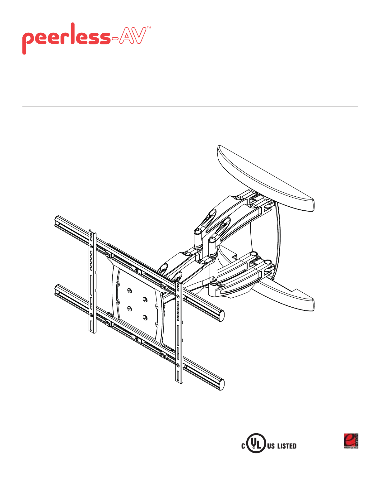
Corrosion Resistant Articulating Mount for Indoor or Outdoor
37" - 63" Flat Panel Displays
Models: ESA763PU
Max UL Load Capacity: 200 lb (90.7 kg)
2300 White Oak Circle • Aurora, Il 60502 • (800) 865-2112 • Fax: (800) 359-6500 • www.peerless-av.com
ISSUED: 01-05-11 SHEET #: 061-9062-7 03-22-12
Page 2
Note: Read entire instruction sheet before you start installation and assembly.
WARNING
• Do not begin to install your Peerless product until you have read and understood the instructions and warnings
contained in this Installation Sheet. If you have any questions regarding any of the instructions or warnings, for US
customers please call Peerless customer care at 1-800-865-2112, for all international customers, please contact
your local distributor.
• This product should only be installed by someone of good mechanical aptitude, has experience with basic building
construction, and fully understands these instructions.
• Due to outdoor environmental conditions such as heavy snow, hail, rain, etc. the environmental mount and
hardware must be inspected at least once a year. This product should not be exposed to high winds. A qualifi ed
installer or inspector must check for signs of rust, loose fasteners, bent metal, etc. If evidence of excessive wear,
deterioration or any unsafe condition is observed, this product must be taken out of service immediately. Direct all
inquiries to customer care if you have any questions.
• Make sure that the supporting surface will safely support the combined load of the equipment and all attached
hardware and components.
• Never exceed the Maximum UL Load Capacity. See page one.
• If mounting to wood wall studs, make sure that mounting screws are anchored into the center of the studs. Use of
an "edge to edge" stud fi nder is highly recommended.
• Always use an assistant or mechanical lifting equipment to safely lift and position equipment.
• Tighten screws fi rmly, but do not overtighten. Overtightening can damage the items, greatly reducing their holding
power.
• This product was designed to be installed on the following wall construction only;
WALL CONSTRUCTION HARDWARE REQUIRED
• Wood Stud Included
• Wood Beam Included
• Solid Concrete Included
• Cinder Block Included
• Metal Stud Contact Qualifi ed Professional (not evaluated by UL)
• Brick Contact Qualifi ed Professional (not evaluated by UL)
• Other or unsure? Contact Qualifi ed Professional
Tools Needed for Assembly
• stud fi nder ("edge to edge" stud fi nder is recommended)
• phillips screwdriver
• drill
• 3/16" (5mm) drill bits for wood studs, 13/32" (10mm) drill bits for concrete
• level
Table of Contents
Parts List.............................................................................................................................................................................3, 4
Wall installation ...................................................................................................................................................................6, 7
Installing Adapter Brackets to Display ...............................................................................................................................8-13
Mounting Flat Panel Display .................................................................................................................................................14
Cable Management ..............................................................................................................................................................16
2 of 50
ISSUED: 01-05-11 SHEET #: 061-9062-7 03-22-12
Page 3
A
K
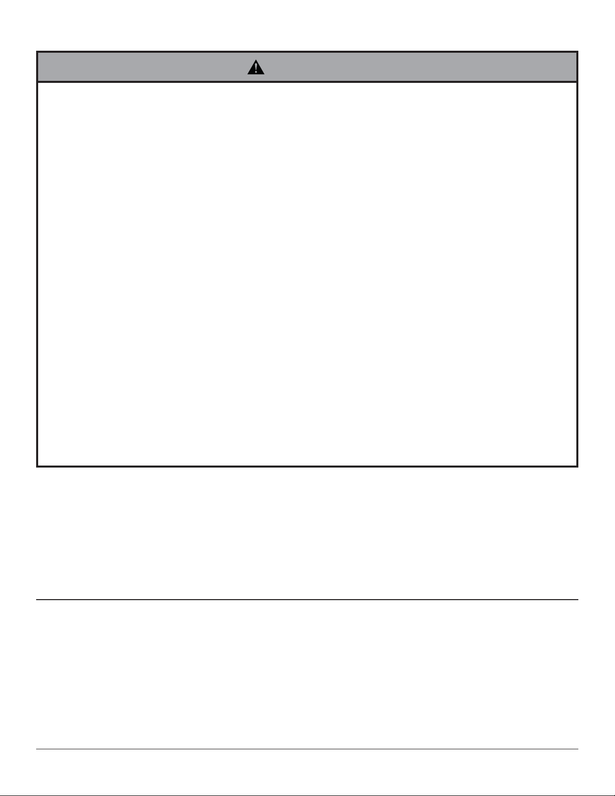
Before you begin, make sure all parts shown are included with your product.
A
Parts List
ESA763PU
Description Qty. Part #
wall arm assembly 1 095-T1994
B universal adapter bracket 1 095-T1635-2
C 3" wood screw 3 520-D1243
D 10mm concrete anchor 4 590-0321
M10 x 15mm socket head screw
E
wall plate cover
F
cable ties
G
H 6mm allen wrench 1 560-9716
I 5mm allen wrench 1 560-9640
J rear cable cover 4 590-P1326
front cable cover 4 590-P1327
L 5/32" allen wrench 1 560-9646
M 2.5" security wood screw 1 520-D1668
Parts may appear slightly different than illustrated.
2
2
16
520-D1262
590-1325
590-1168
B
C
D
H
I
L
J
E
K
F
G
M
3 of 50
ISSUED: 01-05-11 SHEET #: 061-9062-7 03-22-12
Page 4
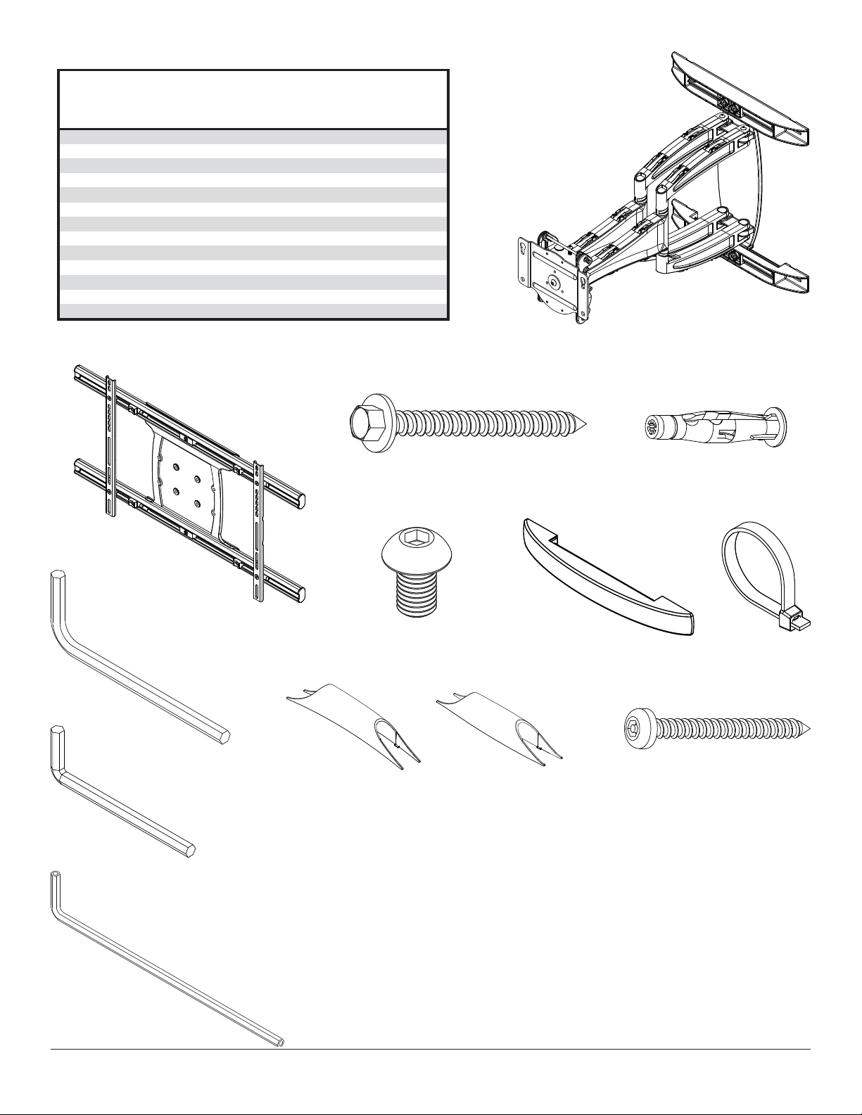
Adapter Bracket Fasteners
M4 x 12 mm (6)
(510-D1079)
M6 x 30 mm (4)
(520-D1067)
M4 x 25 mm (4)
(510-D1082)
M8 x 12 mm (6)
(520-D1068)
M5 x 12 mm (4)
(520-D1064)
M8 x 25 mm (4)
(520-D1101)
M5 x 25 mm (4)
(520-D1122)
M8 x 40 mm (4)
(520-D1152)
M6 x 12 mm (4)
(520-D1050)
I.D. .22" (4)
(540-1057)
I.D. .34" (4)
(540-1059)
M6 x 20 mm (4)
(520-D1554)
M6 x 25 mm (4)
(520-D1211)
multi-washer (6)
(580-D1036)
4 of 50
ISSUED: 01-05-11 SHEET #: 061-9062-7 03-22-12
Page 5
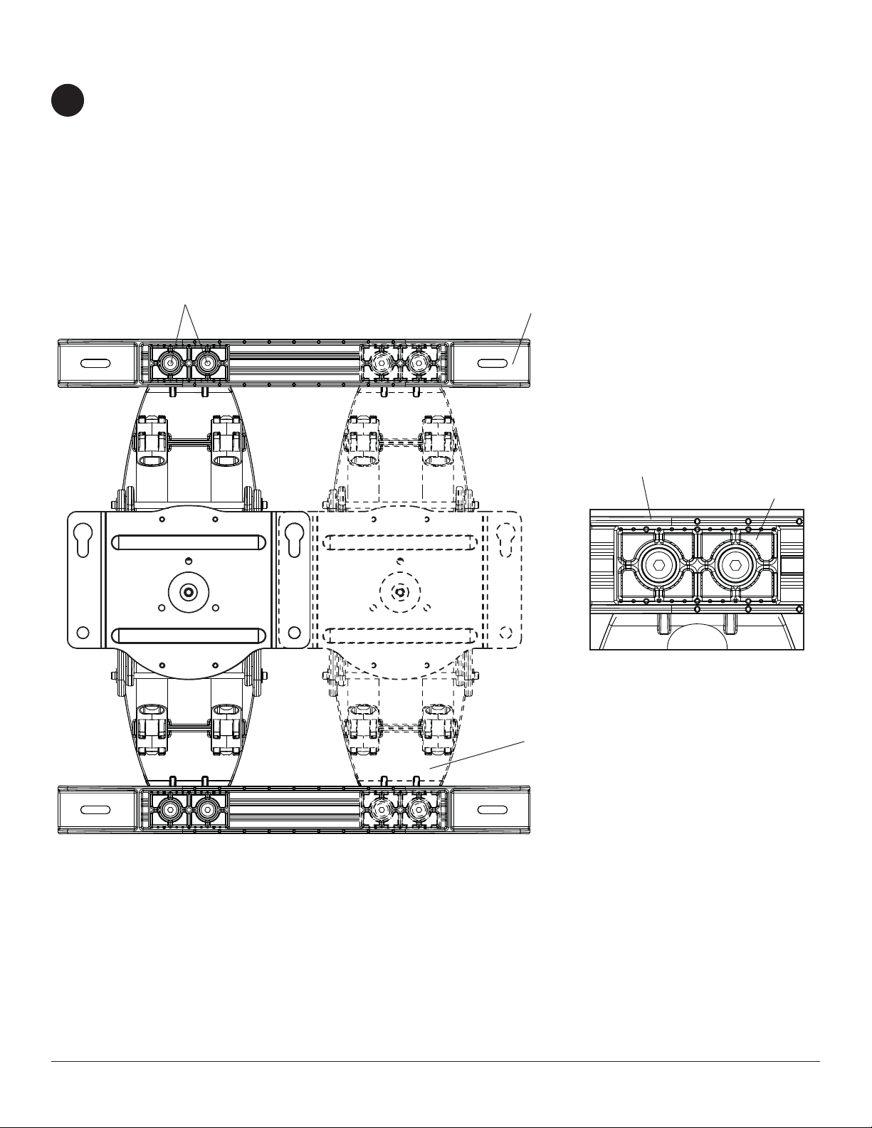
Optional Horizontal Adjustment of Wall Arm on Wall Plate
NOTE: If mounting wall arm (A) to wood stud walls, slots on wall plate must align to wood studs.
1
Determine desired location of display center detailed in step 2.
Measure the distance from the center of wall arm (A) to desired display center. Loosen four 1/4-20 x 17mm screws
using 5mm allen wrench (I). Slide wall arm assembly 4-1/2" to the left or right as shown in fi gure 1.1. NOTE: Align
bevels (dots) of slide plate with bevels (dots) of wall plate rails as shown in detail 1 then retighten 1/4-20 x 17mm
screws.
Do not adjust arm while display is attached.
Skip to page 6 for Wood Stud Installation.
Skip to page 7 for Concrete and Cinder Block Installation.
1/4-20 X 17 MM SCREWS
WALL PLATE
WALL PLATE RAIL
SLIDE PLATE
DETAIL 1
fi g. 1.1
5 of 50
WALL ARM
ISSUED: 01-05-11 SHEET #: 061-9062-7 03-22-12
Page 6
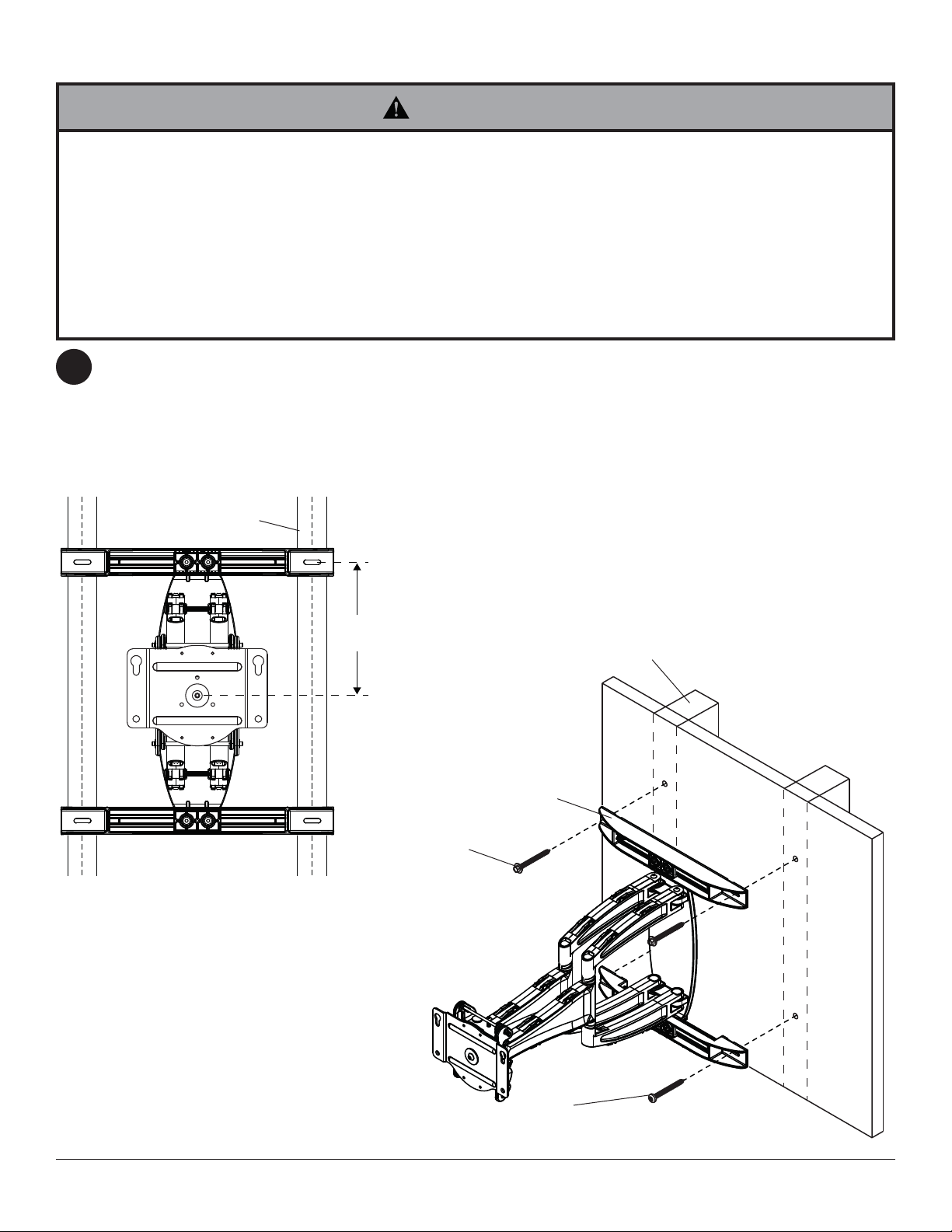
Installation to Double-Stud Wall
WARNING
• Installer must verify that the supporting surface will safely support the combined load of the equipment and all
attached hardware and components.
• Tighten wood screws so that wall plate is fi rmly attached, but do not overtighten. Overtightening can damage the
screws, greatly reducing their holding power.
• Never tighten in excess of 80 in. • lb (9 N.M.).
• Make sure that mounting screws are anchored into the center of the stud. The use of an "edge to edge" stud fi nder
is highly recommended.
• Hardware provided is for attachment of mount through standard thickness drywall or plaster into wood studs.
Installers are responsible to provide hardware for other types of mounting situations (not evaluated by UL).
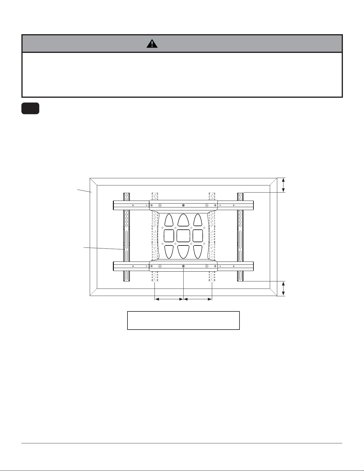
Use a stud fi nder to locate the edges of the studs and draw a vertical line down the center of each stud. Determine
2
and mark the desired display center on the wall. Place wall plate template (wall arm) on wall with top mounting slots
9" (229mm) above desired display center as shown in fi gure 2.1. Level wall plate template (wall arm) on wall and
mark center of four mounting holes making sure that the mounting holes are on the stud centerlines. Drill four 3/16"
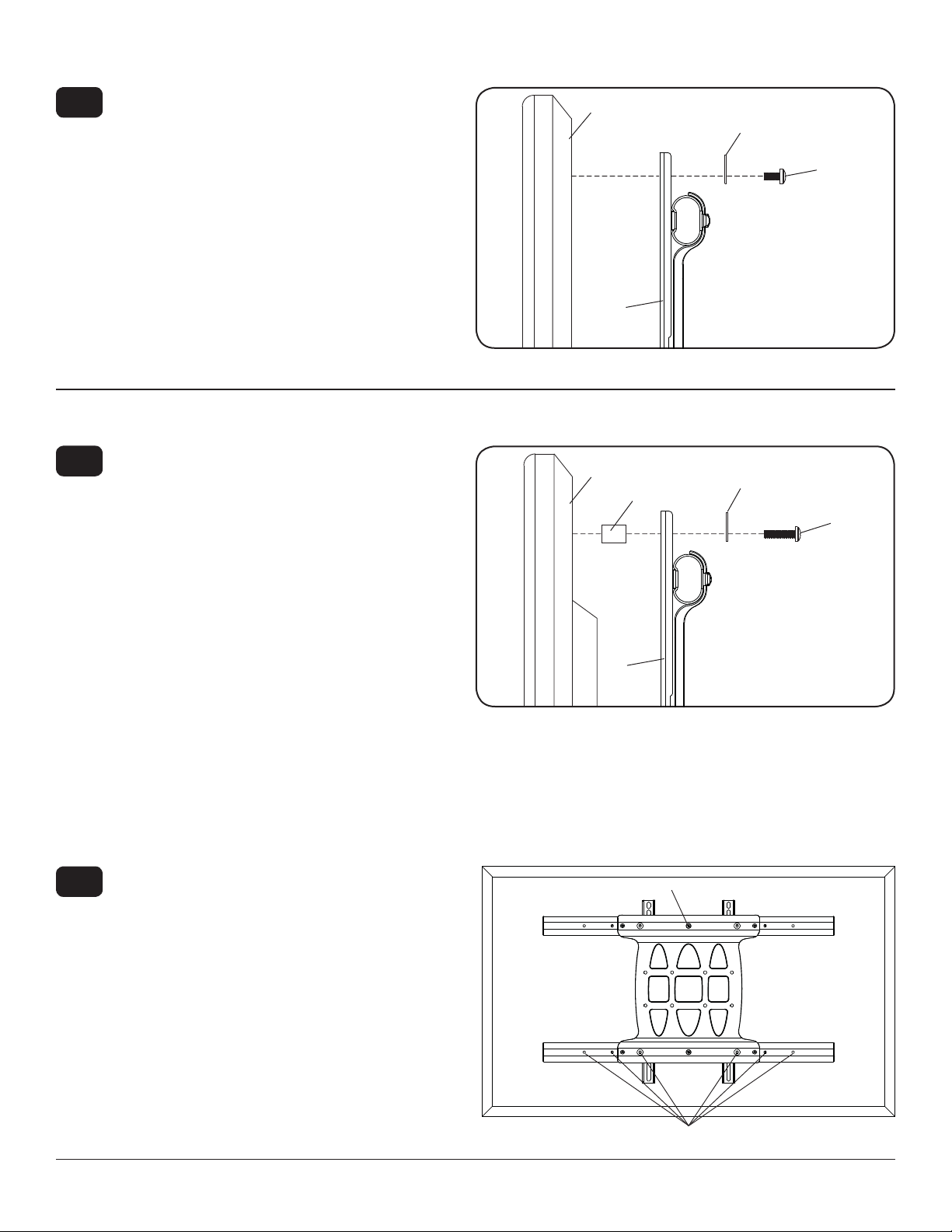
(5mm) dia. pilot holes to a depth of 3" (76mm). Attach wall arm (A) to wall using three wood screws (C) and one
security wood screw (M) as shown in fi g. 2.2.
Level wall plate then tighten all fasteners.
WOOD STUD
CS
CS = CENTER OF DISPLAY
fi g. 2.1
9"
(229 mm)
C
5/16" WOOD
SCREW
WOOD STUD
A
6 of 50
M
#14 SECURITY
SCREW
fi g. 2.2
ISSUED: 01-05-11 SHEET #: 061-9062-7 03-22-12
Page 7
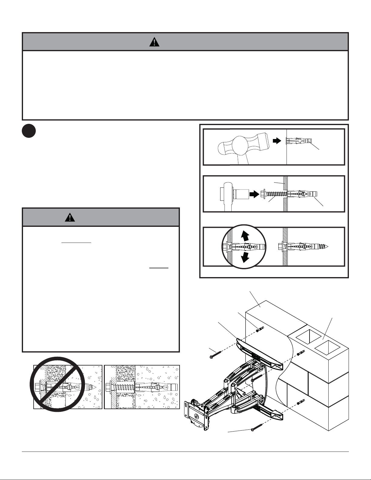
Installation to Solid Concrete or Cinder Block
WARNING
• When installing Peerless wall mounts on cinder block, verify that you have a minimum of 1-3/8" (35mm) of actual
concrete thickness in the hole to be used for the concrete anchors. Do not drill into mortar joints! Be sure to mount
in a solid part of the block, generally 1" (25mm) minimum from the side of the block. Cinder block must meet ASTM
C-90 specifi cations. It is suggested that a standard electric drill on slow setting is used to drill the hole instead of a
hammer drill to avoid breaking out the back of the hole when entering a void or cavity.
• Concrete must be 2000 psi density minimum. Lighter density concrete may not hold concrete anchor.
• Make sure that the supporting surface will safely support the combined load of the equipment and all attached
hardware and components.
Determine and mark the desired display center on the
2
2
wall. Place wall plate template (wall arm) on wall with
top mounting slots 9" (229mm) above desired display
center as shown in fi gure 2.1 on page 6. Level wall
plate template (wall arm) on wall and mark center of
four mounting holes. Drill four 13/32" (10mm) dia. pilot
holes to a depth of 3" (76mm). Insert anchors (D) into
four holes fl ush with wall as shown (right). Place wall
arm (A) over anchors and secure using three wood
screws (C) and one security wood screw (M). Level,
then tighten all fasteners.
WARNING
1
D
Drill holes and insert anchors (D).
2
A
C,M
Place plate (A) over anchors (D) and secure with screws (C,M).
concrete
surface
D
• Tighten screws so that wall plate is fi rmly attached,
but do not overtighten. Overtightening can damage
screws, greatly reducing their holding power.
• Never tighten in excess of 80 in. • lb (9 N.M.).
• Always attach concrete expansion anchors directly
to load-bearing concrete.
• Never attach concrete expansion anchors to
concrete covered with plaster, drywall, or other
fi nishing material. If mounting to concrete surfaces
covered with a fi nishing surface is unavoidable (not
evaluated by UL), the fi nishing surface must be
counterbored as shown below. Be sure concrete
anchors do not pull away from concrete when
tightening screws. If plaster/drywall is thicker than
5/8" (16mm), custom fasteners must be supplied by
installer (not evaluated by UL).
INCORRECT CORRECT
plate
CUTAWAY VIEW
wall
plaster/
dry wall
concrete
wall
plate
plaster/
dry wall
concrete
3
Tighten all fasteners.
A
C
5/16" WOOD
SCREW
SOLID CONCRETE
D
CINDER BLOCK
7 of 50
M
#14 SECURITY
SCREW
ISSUED: 01-05-11 SHEET #: 061-9062-7 03-22-12
fi g. 2.3
Page 8
Installing Adapter Brackets to Display
NOTE: If display has a VESA 400 horizontal
mounting pattern, skip to step 3-3 or 3-4 on page
10.
NOTE: For VESA 200x200 or VESA 200x100
mount hole patterns, skip to step 4 on page 11.
NOTE: For dedicated PLP plate installation skip to
step 5 on page 13.
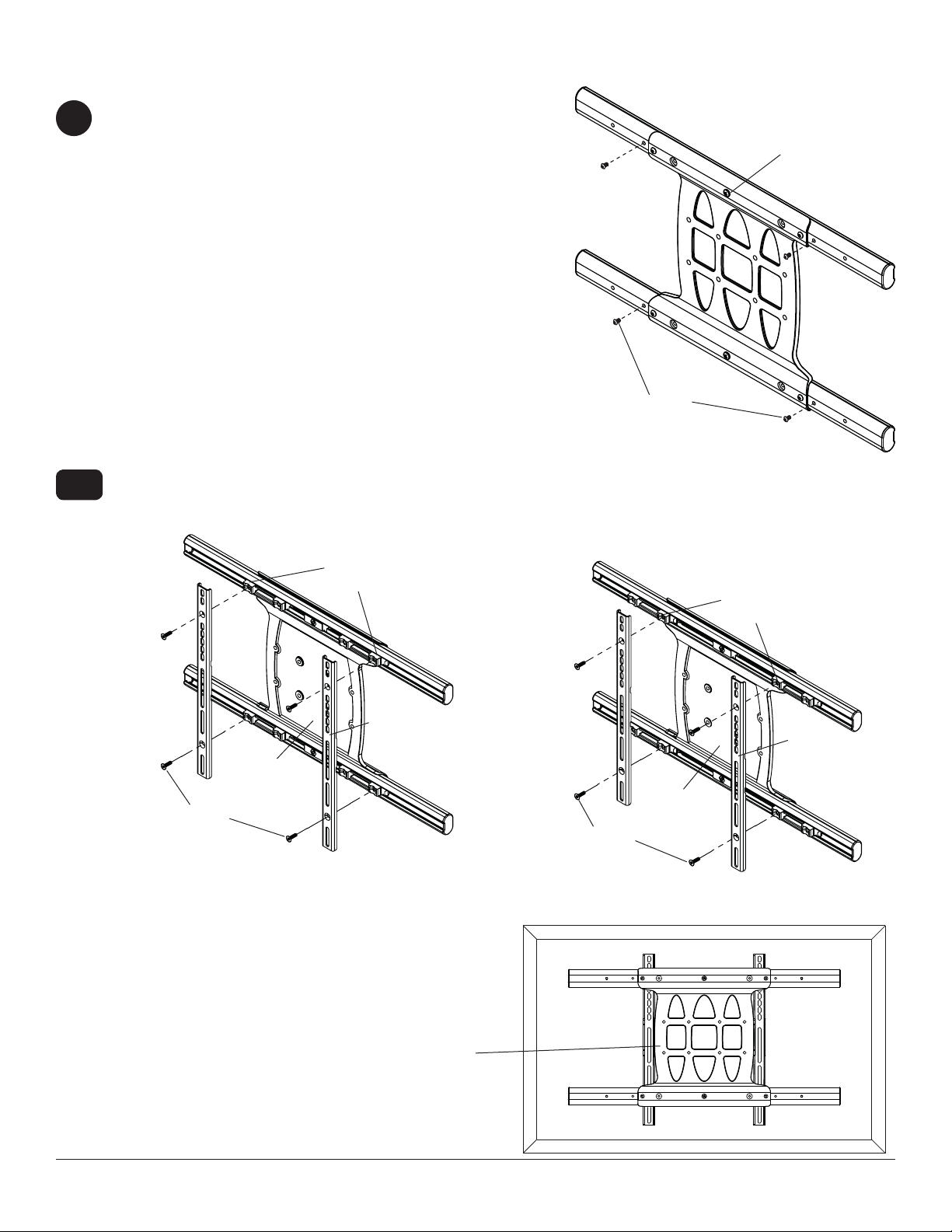
Remove four 1/4-20 x .6" screws using 5 mm allen
3
wrench (I) and loosen two 1/4-20 x 1.25" screws
1/2 turn to allow for display bracket adjustment.
1/4-20 x 1.25" SCREWS
1/4-20 x .6" SCREWS
3-1
To prevent scratching the display, set a cloth on a fl at, level surface that will support the weight of the display.
Place display face side down and refer to display manufacturers instructions for removing obstructions from the
back of the display. Adjust display brackets to align with display mounting holes.
Measure horizontal mounting hole pattern and choose fi xed stop-position from chart below.
horizontal mounting hole pattern fixed stop-position
10-3/4" - 16-1/16" (273 - 408 mm) #1
15-1/16" - 21-9/16" (383 - 548 mm) #2
20-7/16" - 27-9/16" (519 - 700 mm) #3
FIXED STOP-POSTION #3
FIXED STOP-POSTION #2
FIXED STOP-POSTION #1
8 of 50
ISSUED: 01-05-11 SHEET #: 061-9062-7 03-22-12
Page 9
Installing Adapter Brackets to Display
WARNING
• Tighten screws so display brackets are fi rmly attached to display. Do not tighten with excessive force.
Overtightening can cause stress damage to screws, greatly reducing their holding power and possibly causing
screw heads to become detached. Tighten to 40 in. • lb (4.5 N.M.) maximum torque.
• If screws don't get three complete turns in the display inserts or if screws bottom out and bracket is still not tightly
secured, damage may occur to display or product may fail.
3-2
DISPLAY BRACKETS
Select the screws from the baffl ed fastener pack that best fi t your display and secure to display following step 3-3
or 3-4 on page 10.
NOTE: Top and bottom mounting holes must be used for attaching display brackets. Middle holes should also be
used where the fasteners and displays allow.
Verify that all holes are properly aligned, then tighten screws using a phillips screwdriver.
DISPLAY
CENTER DISPLAY BRACKETS VERTICALLY AND
HORIZONTALLY ON BACK OF DISPLAY
X
Y
NOTE: "X" dimensions should be equal.
"Y" dimensions should be equal.
9 of 50
Y
X
ISSUED: 01-05-11 SHEET #: 061-9062-7 03-22-12
Page 10
For Flat Back Display
3-3
Begin with the shortest length screw, hand thread
screw through multi-washer and display brackets
(B) into display as shown below. Screw must make
at least three full turns into the mounting hole and
fi t snug into place. Do not over tighten. If screw
cannot make three full turns into the display, select
a longer length screw from the baffl ed fastener
pack. Repeat for remaining mounting holes, level
display brackets and tighten screws.
NOTE: Spacers may not be used, depending upon
the type of display.
Skip to step 3-5.
For Bump-out or Recessed Back Display
3-4
Begin with the longest length screw, hand thread
screw through multi-washer, display brackets (B)
and spacer in that order into display as shown
below. Screw must make at least three full turns
into the mounting hole and fi t snug into place.
Do not over tighten. If screw cannot make three
full turns into the display, select a shorter length
screw from the baffl ed fastener pack. Repeat for
remaining mounting holes, level display brackets
and tighten screws.
DISPLAY
B
DISPLAY
SPACER
MULTI-WASHER
SCREW
MULTI-WASHER
SCREW
3-5
Center display brackets horizontally and vertically
on back of display. Tighten two 1/4-20 x 1.25"
screws. Reinstall four 1/4-20 x .6" screws using
5 mm allen wrench (I) into appropriate fi xed-stop
position from chart on page 8.
B
1/4-20 x 1.25" SCREWS
10 of 50
1/4-20 x .6" SCREWS
ISSUED: 01-05-11 SHEET #: 061-9062-7 03-22-12
Page 11
VESA 200 x 200 or VESA 200 x 100 Mounting Pattern
Remove four 1/4-20 x .6" screws using 5mm allen wrench
4
(I) and loosen two 1/4-20 x 1.25" screws 1/2 turn to allow for
display bracket adjustment.
1/4-20 x .6" SCREWS
1/4-20 x 1.25" SCREWS
4-1
Remove four 1/4-20 self tapping screws to detach display brackets from outer mount holes of universal adapter
bracket (B) using 5mm allen wrench (I) as shown in fi gure 4.1. Reinstall four 1/4-20 self tapping screws to secure
display brackets to inner set of mounting holes on universal adapter bracket (B) as shown in fi gure 4.2.
1/4-20 SELF
T APPING SCREWS
To prevent scratching the display, set a cloth on a
fl at, level surface that will support the weight of the
display. Place display face side down and place
universal adapter bracket (B) onto display.
B
fi g. 4.1
OUTER
MOUNTING
HOLES
DISPLAY
BRACKETS
INNER
MOUNTING
HOLES
DISPLAY
BRACKETS
B
1/4-20 SELF
T APPING SCREWS
fi g. 4.2
B
11 of 50
ISSUED: 01-05-11 SHEET #: 061-9062-7 03-22-12
Page 12
VESA 200 x 200 or VESA 200 x 100 Mounting Pattern (Continued)
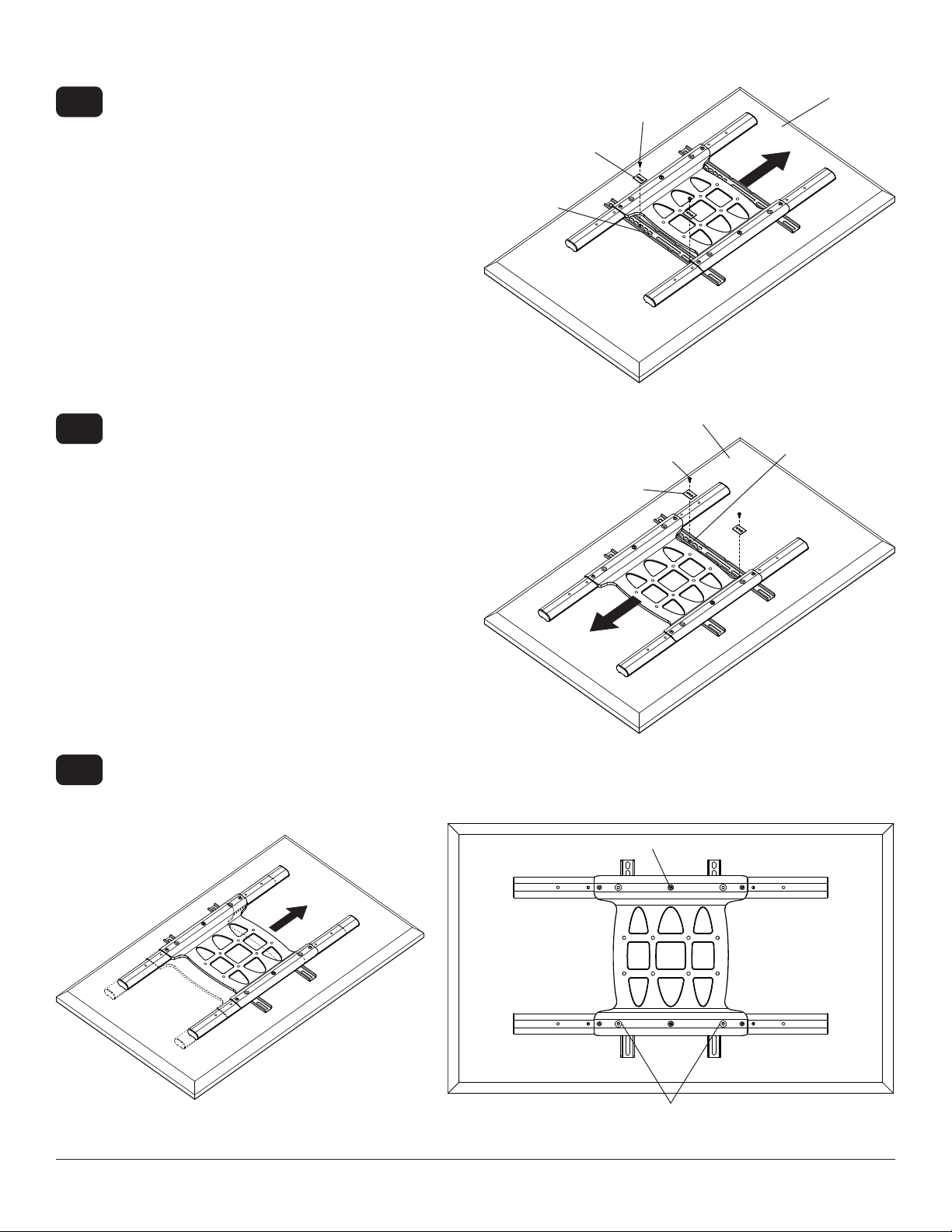
4-2
Align one display bracket with one set of display
mounting holes.
Begin with the shortest length screw, hand thread
screw through multi-washer and display brackets
into display as shown. Screw must make at least
three full turns into the mounting hole and fi t snug
into place. Do not over tighten. If screw cannot
make three full turns into the display, select a longer
length screw from the baffl ed fastener pack. Center
display brackets vertically and tighten screws.
NOTE: For displays with a bump-out or recessed
back, spacer may be used. Spacer goes between
display bracket and display.
SCREW
MULTI-
WASHER
DISPLAY
BRACKET
DISPLAY
4-3
4-4
Slide universal adapter bracket to the opposite side
and align second display bracket with second set of
display mounting holes.
Hand thread screws through multi-washer, display
bracket, and spacer if used, into display as shown.
Tighten all screws.
Center display brackets horizontally on back of display as shown in fi gure 4.3.
Tighten two 1/4-20 x 1.25" screws. Reinstall four 1/4-20 x .6" screws using 5 mm allen wrench (I) into fi xed-stop
position 1 as shown in fi gure 4.4.
MULTI-WASHER
1/4-20 x 1.25" SCREWS
DISPLAY
SCREW
DISPLAY
BRACKET
fi g. 4.3
fi g. 4.4
12 of 50
FIXED STOP POSITION #1 WITH
1/4-20 x .6" SCREWS
ISSUED: 01-05-11 SHEET #: 061-9062-7 03-22-12
Page 13
WARNING
• Do not lift more weight than you can handle. Use additional man power or mechanical lifting equipment to safely
handle placement of the display.
• Do not tighten screws with excessive force. Overtightening can cause damage to mount. Tighten M10 x 15mm
screws (E) to 40 in. • lb (4.52 N.M.) maximum torque.
Mounting Flat Panel Display
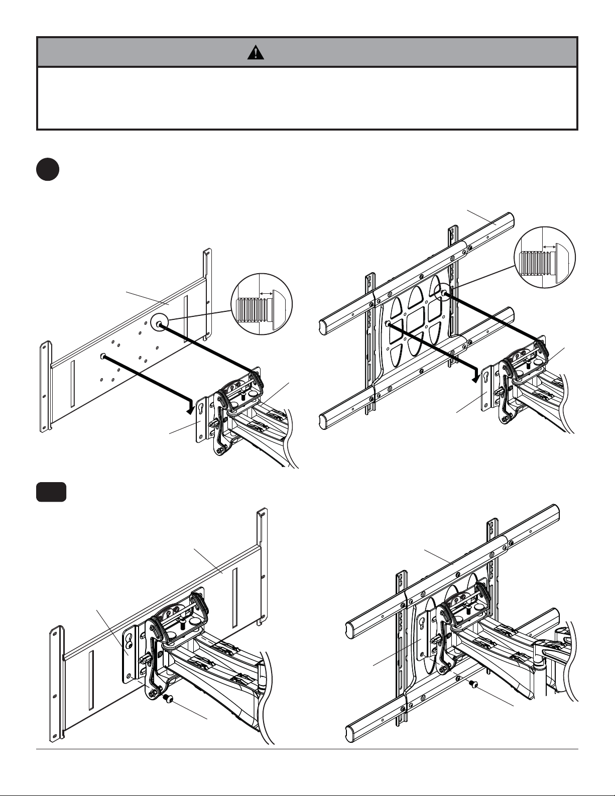
For Dedicated PLP Plate (not evaluated by UL):
5
Refer to PLP model instruction sheet for attachment
of dedicated PLP plate to display.
Install two M10 x 15mm screws (provided with
dedicated PLP plate) into top two holes of dedicated
PLP plate leaving 1/4" of exposed thread as shown
in fi gure 5.1.
For Universal Adapter Bracket: Hook M10 x 15mm
screws into keyslots of wall arm adapter plate (A) as
shown fi gure 5.2.
B
DISPLAY NOT
SHOWN FOR
CLARITY
1/4"
5-1
DEDICATED
PLP PLATE
1/4"
M10 X 15 MM
SCREW
M10 X 15 MM
SCREW
A
ADAPTER PLATE
ADAPTER PLATE
fi g. 5.2
fi g. 5.1
Insert two M10 x 15mm screws (E) into bottom holes of adapter plate as shown in fi gure 5.3 or 5.4. Tighten all
fasteners with 6mm allen wrench (H).
DEDICATED PLP PLATE
B
A
ADAPTER PLATE
ADAPTER PLATE
fi g. 5.3 fi g. 5.4
E
13 of 50
ISSUED: 01-05-11 SHEET #: 061-9062-7 03-22-12
E
Page 14
Adjustment of Flat Panel Display
WARNING
• M10 x 15mm screws (E) must be securly tightened before changing orientation of wall arm assembly (A). Failure to
lock adapter bracket can cause display to come off of mount.
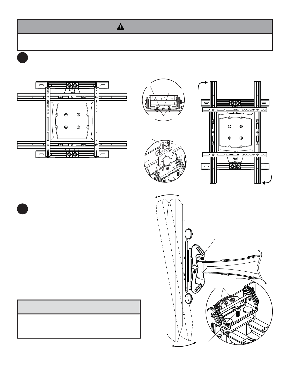
FOR PORTRAIT OR LANDSCAPE DISPLAY ORIENTATION: Remove two M5 x 12mm screws, one M5 x 6mm
6
screw and rotation block from top of tilt head as shown in top view and rear view. Gently grasp sides of display and
rotate display into portrait or landscape position as shown in fi gure 6.1 and reinstall rotation block with two
M5 x 12mm screws and one M5 x 6mm screw. NOTE: M5 x 6mm screw required in landscape orientation only.
ROTATION BLOCK
M5 X 6MM SCREWS
M5 X 12MM SCREWS
TOP VIEW
TIL T Adjustment: Adjust tension knob on side of
7
mount to desired tension to enable tilt adjustment
and balance your display size and weight. Push
or pull from top or bottom of display to adjust tilt
as shown. The tilt can be adjusted to a maximum
of 10° forward or 5° backward. Retighten tension
knob.NOTE: For larger displays, tension screw on
opposite side of mount may need to be tightened
using 5/32" allen wrench (L).
ROLL Adjustment: Rotate display 5° clockwise or
counter-clockwise, level display then tighten
M5 x 10mm roll screws using 5mm allen wrench (I)
as shown in detail 2.
FOR VERTICAL HEIGHT ADJUSTMENT: Tighten
or loosen M8 x 40mm screw to achieve ± 1" of
vertical height adjustment as shown in detail 2.
M5 X 6MM
SCREWS
ROTATION BLOCK
REAR VIEW
M5 X 12MM
SCREWS
fi g. 6.1
TENSION KNOB
M5 X 10MM
SCREWS
CAUTION
• Do not tighten screws with excessive force.
• Be careful not to pinch fi ngers when opening and
closing mount from the wall.
14 of 50
M8 X 40MM
SCREW
ISSUED: 01-05-11 SHEET #: 061-9062-7 03-22-12
DETAIL 2
Page 15
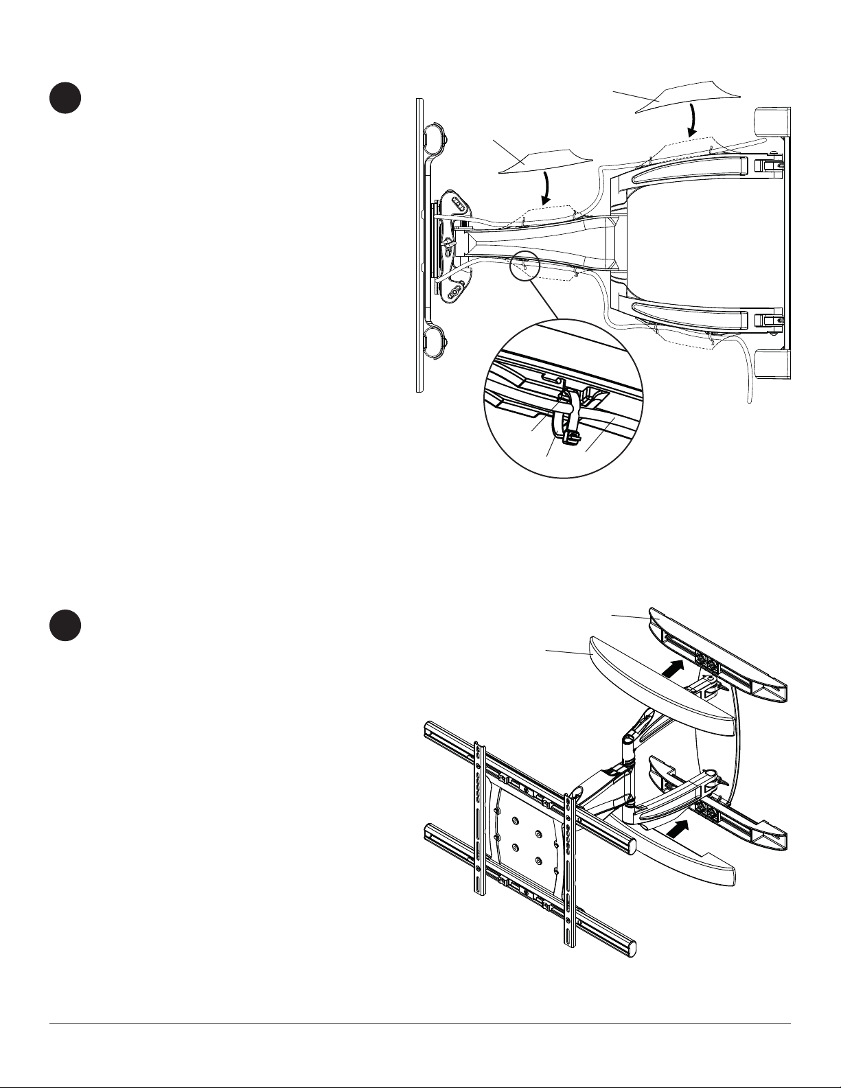
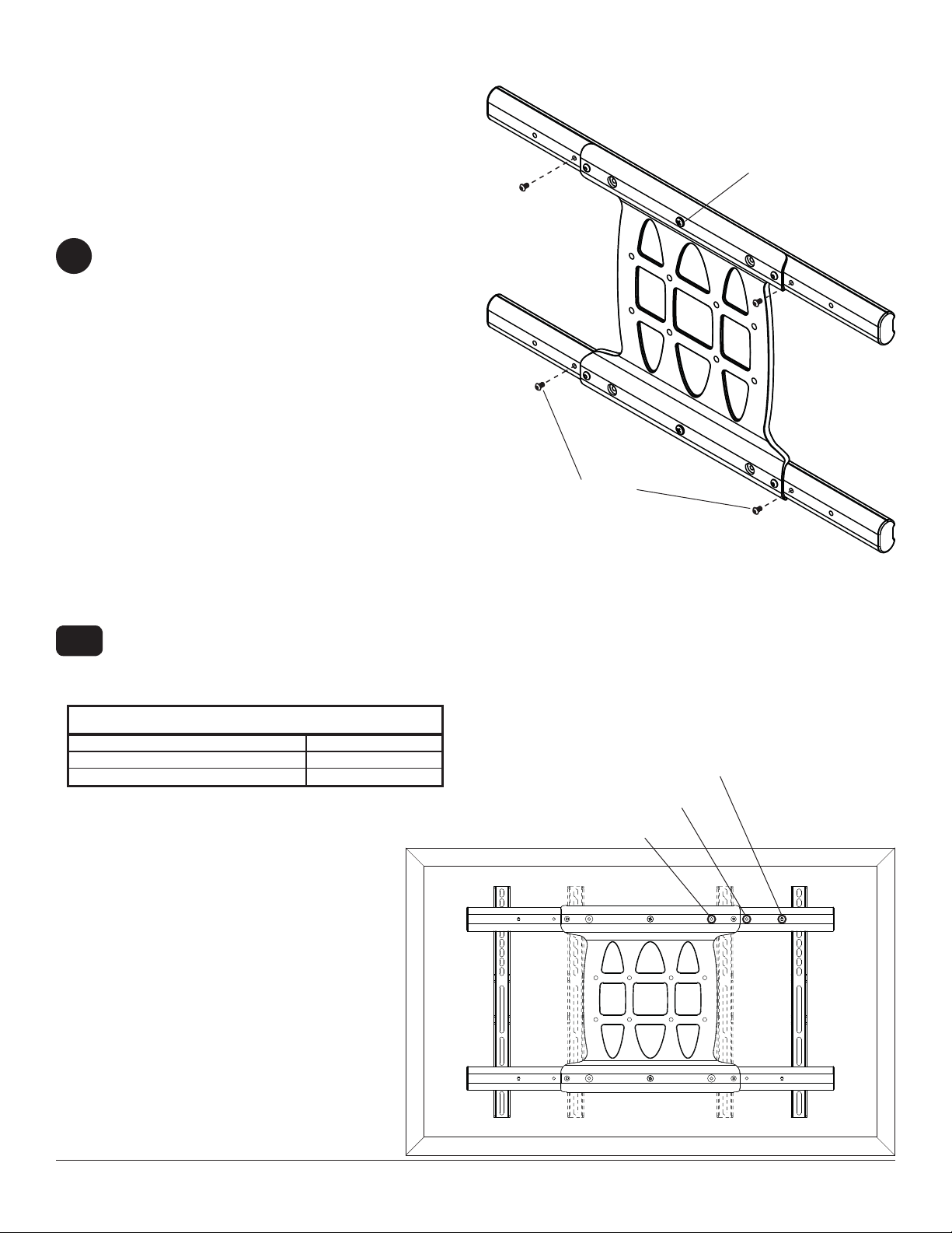
Cable Management
NOTE: Make sure cables have enough slack to
8
allow full movement of the arm.
Run power cable through top or bottom of arm (A)
and signal cable(s) through other side of arm in
order to avoid interference with the signal. Lock
cables into place by snapping cable covers (J &
K) onto mount as shown. Display may have to be
moved for easy access.
Optional: If additional cable management is
required route cable ties (G) through slots of arm (A)
as shown in detail 3.
K
SLOT
G
J
A
CABLE
Snap wall plate covers (F) to top and bottom of wall
9
plate rails as shown.
DETAIL 3
WALL PLATE RAIL
F
15 of 50
ISSUED: 01-05-11 SHEET #: 061-9062-7 03-22-12
Page 16

Arm Tension Adjustment
WARNING
• Do not remove screw or loosen screw until it is no longer engaged with the mount. Doing so may cause the display
to fall.
• If screws become loose over time, tighten screws as necessary. Tighten screws to 50 in • lbs (5.6 N.m.) maximum
torque.
If more or less tension is desired in the arm pivot points, do the following:
10
• To increase tension, turn socket screw clockwise with 5mm allen wrench (I). NOTE: Tighten screws to
50 in • lbs (5.6 N.m.) maximum torque.
• To reduce tension, turn socket screw counter-clockwise with 5mm allen wrench (I). NOTE: Do not turn more
than half a turn.
TENSION SCREW
TENSION SCREWS
16 of 50
ISSUED: 01-05-11 SHEET #: 061-9062-7 03-22-12
All other brand and product names are trademarks or registered trademarks of their respective owners.
© 2012, Peerless Industries, Inc. All rights reserved.
Page 17

Instalación y montaje:
Soporte articulador resistente a la corrosión para pantallas
planas de 37" a 63" para uso en interiores y exteriores
Modelos: ESA763PU
Màxima capcaidad de carga: 200 lb (90.7 kg)
2300 White Oak Circle • Aurora, Il 60502 • (800) 865-2112 • Fax: (800) 359-6500 • www.peerless-av.com
PUBLICADO: 01-05-11 HOJA #: 061-9062-7 03-22-12
Page 18

Español
NOTA: Lea la hoja de instrucciones completa antes de comenzar la instalación y el ensamblaje.
ADVERTENCIA
• No comience a instalar su producto de Peerless hasta haber leído y entendido las instrucciones y las advertencias
contenidas en la Hoja de Instalación. Si tiene alguna pregunta acerca de cualquiera de las instrucciones o las
advertencias, por favor, llame a Servicio al Cliente de Peerless al 1-800-865-2112 si está en EE. UU. Si es un cliente
internacional, por favor, comuníquese con su distribuidor local.
• Este producto sólo debe ser instalado por una persona que tenga una buena aptitud mecánica, que tenga
experiencia en construcción básica de edifi cios y que entienda estas instrucciones en su totalidad.
• Debido a condiciones ambientales, como grandes cantidades de nieve, granizo, lluvia, etc., el soporte y los
accesorios se tienen que inspeccionar, por lo menos, una vez al año. Este producto no debe estar expuesto a fuertes
vientos. Un instalador o inspector califi cado debe revisar el soporte para detectar señales de oxidación, sujetadores
sueltos, metales doblados, etc. Si se detectan señales de desgaste excesivo, deterioro o cualquier condición que no
sea segura, se debe descontinuar el uso del producto de inmediato. Dirija todas sus preguntas a Servicio al Cliente,
si tiene alguna.
• Asegúrese de que la superfi cie de apoyo sostendrá, con seguridad, la carga combinada del equipo y todos los
fi jadores y componentes.
• Nunca sobrepase la capacidad máxima de soportar carga aceptada por Underwriters Laboratories. Vea la página 17.
• Si va a instalar el producto en una pared con montantes de madera, asegúrese de que los tornillos de montaje estén
anclados en el centro de los montantes. Se recomienda utilizar un localizador de montantes de "borde a borde".
• Siempre cuente con la ayuda de un asistente o utilice un equipo mecánico de izar para levantar y colocar el equipo
con más seguridad.
• Apriete los tornillos con fi rmeza, pero no en exceso. Apretarlos en exceso puede dañar los artículos y puede
disminuir signifi cativamente su fuerza de fi jación.
• Este producto fue diseñado para ser instalado en paredes con la siguiente construcción solamente:
CONSTRUCCIÓN DE LA PARED ACCESORIOS NECESARIOS
• Montante de madera Incluido
• Viga de madera Incluido
• Concreto macizo Incluido
• Bloque de hormigón de escorias Incluido
• Montante de metal No lo instale excepto con el juego de accesorios de Peerless para
montantes de metal (no evaluados por UL)
• Ladrillo Comuníquese con un profesional califi cado (no evaluados por UL)
• ¿Otra superfi cie o no está seguro? Comuníquese con un profesional califi cado
Herramientas necesarias para el ensamblaje
• localizador de montantes (se recomienda uno de "borde a borde")
• destornillador phillips
• taladro
• broca de 13/32" (10 mm) para paredes de concreto y de bloque de hormigón de escorias, broca de 3/16" (5 mm) para
paredes con montantes de madera
• nivel
Tabla de Contenido
Lista de piezas................................................................................................................................................................19, 20
Instalación en una pared ................................................................................................................................................22, 23
Instalación del soporte adaptador universal ....................................................................................................................24-28
Instalación de la pantalla plana ............................................................................................................................................29
Manejo de los cables ............................................................................................................................................................32
18 de 50
PUBLICADO: 01-05-11 HOJA #: 061-9062-7 03-22-12
Page 19

Antes de empezar, asegúrese de que todas las piezas que se muestran
A
K
son incluidos con su producto.
Español
A
Lista de piezas
ESA763PU
Descripción Cant. N° de pieza
brazo de pared 1 095-T1994
B soporte adaptador universal 1 095-T1635-2
C 3" tornillos para madera 3 520-D1243
D 10mm anclajes de concreto 4 590-0321
tornillos de M10 x 15mm
E
cubiertas de la placa de pared
F
sujetacables
G
H llave allen de 6mm 1 560-9716
I llave allen de 5mm 1 560-9640
J Cubierta trasera para cables 4 590-P1326
Cubierta delantera para cables 4 590-P1327
L llave allen de 5/32" 1 560-9646
M 2.5" tornillo de seguridad para madera 1 520-D1668
Las piezas pueden verse un poco distintas a la ilustración.
2
2
16
520-D1262
590-1325
590-1168
B
C
D
H
I
L
J
E
K
F
G
M
19 de 50
PUBLICADO: 01-05-11 HOJA #: 061-9062-7 03-22-12
Page 20

Fijaciones para los soportes adaptadores
Español
M4 x 12 mm (6)
(510-D1079)
M6 x 30 mm (4)
(520-D1067)
M4 x 25 mm (4)
(510-D1082)
M8 x 12 mm (6)
(520-D1068)
M5 x 12 mm (4)
(520-D1064)
M8 x 25 mm (4)
(520-D1101)
M5 x 25 mm (4)
(520-D1122)
M8 x 40 mm (4)
(520-D1152)
M6 x 12 mm (4)
(520-D1050)
I.D. .22" (4)
(540-1057)
I.D. .34" (4)
(540-1059)
M6 x 20 mm (4)
(520-D1554)
M6 x 25 mm (4)
(520-D1211)
arandela
múltiple (6)
(580-1036)
20 de 50
PUBLICADO: 01-05-11 HOJA #: 061-9062-7 03-22-12
Page 21

Ajuste horizontal opcional del brazo de pared en la placa de pared
NOTA: Si el brazo de pared (A) se va a instalar en una pared con montantes de madera, las ranuras de la placa de
1
pared se tienen que alinear con los montantes.
Señale el punto donde quiere que quede el centro de la pantalla, como se explica en el paso 2.
Mida la distancia desde el centro del brazo de pared (A) hasta el punto donde quiere que quede el centro de la
pantalla. Afl oje los cuatro tornillos de 1/4-20 x 17mm utilizando una llave allen de 5mm (I). Deslice la unidad del
brazo de pared 4-1/2" hacia la izquierda o la derecha, como se muestra en la fi gura 1.1. NOTA: Alinee los biseles
(puntos) de la placa deslizable con los biseles (puntos) de los rieles de la placa de pared, como se muestra en el
detalle 1; luego, vuelva a apretar los tornillos de 1/4-20 x 17mm.
No ajuste el brazo de pared si la pantalla ya se ha fi jado al mismo.
Proceda a la página 22 para leer las instrucciones de instalación en una pared con montantes de madera.
Proceda a la página 23 para leer las instrucciones de instalación en una pared de concreto macizo o de bloques de
hormigón de escorias.
Español
1/4-20 X 17 MM TORNILLOS
PLACA DE PARED
RIEL DE LA PLACA DE PARED
PLACA DESLIZABLE
DETALLE 1
fi g. 1.1
21 de 50
BRAZO DE
PARED
PUBLICADO: 01-05-11 HOJA #: 061-9062-7 03-22-12
Page 22

Instalación en una pared con montante de madera único
ADVERTENCIA
• El instalador debe verifi car que la superfi cie de apoyo sea capaz de soportar fi rmemente la carga combinada del
equipo y todos los herrajes y componentes.
• Apriete los tornillos para madera de tal modo que la placa de apoyo quede fi rmemente sujeta, pero no apriete en
exceso. El apriete excesivo puede dañar los tornillos, reduciendo enormemente su fuerza de fi jación.
• Nunca apriete más de 80 pulg-lb (9 N•m).
• Asegúrese de que los tornillos de montaje queden bien fi jos en el centro del montante. Se recomienda usar un
localizador de montantes de "borde a borde".
• Los herrajes suministrados son para fi jar el soporte a través de tabique de yeso-cartón o yeso de espesor
estándar a los montantes de madera. Los instaladores son responsables de suministrar los herrajes para otros
tipos de situaciones de montaje (no evaluados por UL).
Utilizando un localizador de montantes, localice y marque los bordes de los montantes de madera. Se recomienda
2
utilizar un localizador de montantes de "borde a borde". Utilice un nivel para trazar una línea vertical por el centro
de cada montante. Coloque la plantilla de la placa de pared (brazo de pared) nivelada contra la pared y marque
el centro de los cuatro agujeros de montaje en el centro de cada montante de madera. Los agujeros de montaje
superiores deben estar ubicados a 9" (229mm) encima del punto donde quiere que quede el centro de la pantalla,
como se muestra en la fi gura 2.1, según la tabla 1 de abajo. Taladre cuatro agujeros de 3/16" (5mm) de diámetro
con una profundidad de 3" (76mm). Fije el brazo de pared (A) en la pared usando tres tornillos para madera (C) y
un tornillo de seguridad para madera (M), como se muestra en la fi gura 2.2.
Nivele la placa de pared y apriete todos los sujetadores.
Español
MONTANTE
CS
CP = CENTRO DE LA PANTALLA
fi g. 2.1
9"
(229 mm)
C
TORNILLOS
MEDERA 5/16"
MONTANTE
A
TORNILLO DE SEGURIDAD
M
PARA MADERA
22 de 50
fi g. 2.2
PUBLICADO: 01-05-11 HOJA #: 061-9062-7 03-22-12
Page 23

Español
Instalación en una pared de concreto macizo o de bloques
de hormigón de escorias
ADVERTENCIA
• Cuando instale soportes de pared Peerless en bloques de hormigón de escorias, verifi que que tengan un mínimo de 1-3/8"
(35mm) de superfi cie efectiva de concreto en el agujero que va a utilizar para los anclajes de concreto. ¡No perfore en las juntas
de mortero! Asegúrese de instalar el soporte en una parte sólida del bloque, generalmente a un mínimo de 1" (25mm) del costado
del bloque. El bloque de hormigón de escorias debe ser de conformidad con las especifi caciones C-90 de ASTM. Se sugiere
taladrar el agujero con un taladro eléctrico normal en velocidad lenta en vez de un taladro percutor para evitar romper la parte
trasera del agujero al entrar en un espacio o cavidad.
• El concreto debe tener una densidad mínima de 2000 psi. Un concreto menos denso podría no ser capaz de sujetar el anclaje
para concreto.
• El instalador debe verifi car que la superfi cie de apoyo sea capaz de soportar fi rmemente la carga combinada del equipo y todos
los herrajes y componentes.
Coloque la plantilla de la placa de pared (brazo de
2
pared) para marcar los puntos de los agujeros de
montaje. Los agujeros de montaje superiores deben
estar ubicados a 9" (229mm) encima del punto donde
quiere que quede el centro de la pantalla, como se
muestra en la fi gura 2.1 y en la tabla 1 de la página 22.
Taladre cuatro agujeros de 13/32" (10mm) de diámetro
y 3" (76mm) de profundidad, como se muestra en la
fi gura 2.3. Inserte los anclajes (D) en los agujeros a ras
con la pared, como se muestra (a la derecha). Coloque
el brazo de pared (A) sobre los anclajes y fíjelo
usando tres tornillos para madera (C) y un tornillo de
seguridad para madera (M). Nivele y apriete todos los
sujetadores. Nivele y apriete todos los sujetadores.
1
Perfore los agujeros y después inserte los anclajes (D).
2
A
C,M
Coloque la placa (A) sobre los anclajes (D) y fíjela con
los tornillos (C,M).
superfi cie de
concreto
D
D
ADVERTENCIA
• Apriete los tornillos de tal modo que la placa de apoyo
quede fi rmemente sujeta, pero no los apriete en exceso.
El apriete excesivo puede dañar los tornillos, reduciendo
enormemente su fuerza de fi jación.
• Nunca apriete más de 80 pulg-lb (9 N•m).
• Siempre fi je los anclajes de expansión directamente al
concreto que soporta carga.
• Nunca fi je los anclajes de expansión a una pared de
concreto recubierta con yeso, tabiques de yeso-cartón u otro
material de acabado. Si el montaje a superfi cies de concreto
recubiertas con una superfi cie de acabado es inevitable
(no evaluados por UL), será necesario escariar el acabado,
como se muestra más abajo. Asegúrese de que los anclajes
de concreto no se alejen del concreto al apretar los tornillos.
Si el grosor de la pared de yeso/tabique de yeso-cartón es
mayor que 5/8" (16mm), el instalador deberá suministrar
fi jaciones especiales (no evaluados por UL).
placa
de
pared
INCORRECTO
concreto
placa
pared
de
CORRECTO
concreto
3
Apriete todas las fi jaciones.
CONCRETO MACIZO
A
C
TORNILLOS
MEDERA 5/16"
D
BLOQUE DE HORMIGÓN
DE ESCORIAS
VISTA EN CORTE
yeso / tabique de yeso-cartón
23 de 50
M
TORNILLO DE
SEGURIDAD PARA
MADERA
PUBLICADO: 01-05-11 HOJA #: 061-9062-7 03-22-12
fi g. 2.3
Page 24

Instalación de los soportes adaptadores
NOTA: Si la pantalla tiene una confi guración de
montaje horizontal VESA 400, proceda al paso 3-3
o al 3-4 de la página 26.
NOTA: Si la pantalla tiene una confi guración de
montaje horizontal VESA 200x200 o VESA 200 x
100, proceda al paso 4 de la página 27.
3
NOTA: Para instalar la placa exclusiva PLP,
proceda al paso 5 de la página 29.
Quite los cuatro tornillos de 1/4-20 x .6" utilizando
una llave allen de 5 mm (I) y afl oje los dos tornillos
de 1/4-20 x 1.25" 1/2 vuelta para poder ajustar el
soporte de la pantalla.
Español
TORNILLOS 1/4-20 x 1.25"
TORNILLOS 1/4-20 x .6"
3-1
Para evitar que se raye la pantalla, coloque un trapo sobre una superfi cie plana y nivelada que sostenga el peso
de la pantalla. Coloque la pantalla boca abajo y se refi eren a la pantalla las instrucciones del fabricante para
eliminar las obstrucciones de la parte posterior de la pantalla. Ajuste los soportes de la pantalla para alinear con
los agujeros de montaje de pantalla.
Mida la confi guración de montaje horizontal y escoja una posición fi ja de descanso de la tabla de abajo.
configuración de montaje
horizontal
10-3/4" - 16-1/16" (273 - 408 mm) #1
15-1/16" - 21-9/16" (383 - 548 mm) #2
20-7/16" - 27-9/16" (519 - 700 mm) #3
posición fija de
descanso
POSICIÓN FIJA DE DESCANSO N.O 3
POSICIÓN FIJA DE DESCANSO N.O 2
POSICIÓN FIJA DE DESCANSO N.O 1
24 de 50
PUBLICADO: 01-05-11 HOJA #: 061-9062-7 03-22-12
Page 25

Español
Instalación de los soportes adaptadores
ADVERTENCIA
• Apriete los tornillos de tal modo que los soportes adaptadores queden fi rmemente sujetos. No apriete aplicando demasiada
fuerza. El apriete excesivo puede causar daño por esfuerzo a los tornillos, reduciendo enormemente su fuerza de fi jación y
causando el posible desprendimiento de sus cabezas. Apriete los tornillos a 40 pulg-lb (4.5 N•m) de par torsor máximo.
• Si los tornillos no pueden atornillarse con tres vueltas completas en los insertos de la pantalla, o si los tornillos topan fondo y la
placa todavía no está fi rmemente sujeta, se podría dañar la pantalla o causar la falla del producto.
3-2
Escoja los tornillos de los sujetadores identifi cados y clasifi cados en las divisiones del empaque plástico y luego
fi je los soportes de la pantalla siguiendo el paso 3-3 o el paso 3-4 de la página 26.
NOTA: Siempre se tienen que usar los agujeros superiores y los inferiores para la instalación de los soportes de
la pantalla. También se deben usar los agujeros centrales en los casos en los que los sujetadores y las pantallas
lo permitan. Verifi que que todos los agujeros estén debidamente alineados; luego, apriete los tornillos utilizando
un destornillador phillips.
CENTRALICE LOS SOPORTES DE LA PANTALLA VERTICALMENTE
PANTALLA
EN LA PARTE TRASERA DE LA PANTALLA
X
B
SOPORTES DE
LA PANTALLA
X
Y
NOTA: Las dimensiones "X" deben ser iguales.
Las dimensiones "Y" deben ser iguales.
25 de 50
Y
PUBLICADO: 01-05-11 HOJA #: 061-9062-7 03-22-12
Page 26

Instalación de un televisor que tiene la parte posterior plana
Español
3-3
Comience con uno de los tornillos más cortos,
enrósquelo, con la mano, a través de la arandela
múltiple y el soporte de la pantalla (B) a la parte
posterior de la pantalla, como se muestra abajo.
El tornillo tiene que dar, por lo menos, tres vueltas
completas dentro del agujero de montaje y debe
quedar ajustado en su lugar. No apriete los
tornillos en exceso. Si el tornillo no puede dar tres
vueltas completas al entrar en la parte posterior
de la pantalla, seleccione un tornillo más largo
de los sujetadores identifi cados y clasifi cados
en las divisiones del empaque plástico. Siga el
mismo procedimiento con los agujeros de montaje
restantes, nivele los soportes de la pantalla y
apriete los tornillos.
NOTA: Es posible que no necesite usar los
espaciadores, dependiendo del tipo de pantalla.
Proceda al paso 3-5.
PANTALLA
B
Instalación de un televisor que tiene la parte posterior abultada o empotrada
3-4
Comience con uno de los tornillos más largos,
enrósquelo, con la mano, a través de la arandela
múltiple, los soportes de la pantalla (B) y el
espaciador, en ese orden, a la parte posterior
de la pantalla, como se muestra abajo. El
tornillo tiene que dar, por lo menos, tres vueltas
completas dentro del agujero de montaje y debe
quedar ajustado en su lugar. No apriete los
tornillos en exceso. Si el tornillo no puede dar tres
vueltas completas al entrar en la parte posterior
de la pantalla, seleccione un tornillo más largo
de los sujetadores identifi cados y clasifi cados
en las divisiones del empaque plástico. Siga el
mismo procedimiento con los agujeros de montaje
restantes, nivele los soportes de la pantalla y
apriete los tornillos.
PANTALLA
ESPACIADOR
B
ARANDELA MÚLTIPLE
TORNILLO
ARANDELA MÚLTIPLE
TORNILLO
3-5
Centralice los soportes de la pantalla horizontal
y verticalmente en la parte trasera de la
pantalla. Apriete los dos tornillos de 1/4-20 x
1.25". Reinstale los cuatro tornillos de 1/4-20 x
.6" utilizando una llave allen de 5 mm (I) en la
posición fi ja de descanso apropiada de la tabla de
la página 24.
26 de 50
TORNILLOS 1/4-20 x 1.25"
TORNILLOS 1/4-20 x .6"
PUBLICADO: 01-05-11 HOJA #: 061-9062-7 03-22-12
Page 27

VESA 200 x 200 o VESA 200 x 100 Patrón de montaje
Quite los cuatro tornillos de 1/4-20 x .6" utilizando una llave
4
allen de 5mm (I) y afl oje los dos tornillos de 1/4-20 x 1.25"
1/2 vuelta para poder ajustar el soporte de la pantalla.
TORNILLOS 1/4-20 x .6"
Español
TORNILLOS 1/4-20 x 1.25"
4-1
Quite los cuatro tornillo autorroscante de 1/4-20 para retirar los soportes de la pantalla del soporte adaptador
universal (B) utilizando una llave allen de 5mm (I), como se muestra, como se muestra en la fi gura 4.1. Reinstale
los cuatro tornillo autorroscante de 1/4-20 para fi jar los soportes de pantalla en el grupo interior de agujeros de
montaje en el soporte adaptador universal (B), como se muestra en la fi gura 4.2.
TORNILLO
AUTORROSCANTE
DE 1/4-20
Para evitar que se raye la pantalla, coloque
un trapo sobre una superfi cie plana y nivelada
que sostenga el peso de la pantalla. Coloque la
pantalla boca abajo y coloque el soporte adaptador
universal (B) en la pantalla.
B
AGUJEROS
DE MONTAJE
EXTERIOR
SOPORTES
DE LA
PANTALLA
AGUJEROS
DE MONTAJE
INTERIORES
B
SOPORTES
fi g. 4.1 fi g. 4.2
DE LA
PANTALLA
SOPORTES
DE LA
PANTALLA
27 de 50
PUBLICADO: 01-05-11 HOJA #: 061-9062-7 03-22-12
Page 28

VESA 200 x 200 o VESA 200 x 100 Patrón de montaje (continuacion)
4-2
4-3
Alinee uno de los soportes de la pantalla con
uno de los grupos de agujeros de montaje de la
pantalla.
Comience con el tornillo de longitud más corta,
la mano de rosca a través de múltiples soportes
de la pantalla y la arandela de la pantalla, como
se muestra. El tornillo debe dar por lo menos tres
vueltas completas dentro del agujero de montaje
y debe quedar ajustado en su lugar. No apriete
en exceso. Si el tornillo no puede dar tres vueltas
completas en la pantalla, seleccione un tornillo más
largo de la bolsa de tornillos ordenados. Centralice
los soportes de la pantalla verticalmente y apriete
los tornillos.
NOTA: Si la pantalla tiene la parte posterior
abultada o empotrada, puede utilizar el espaciador.
El espaciador va entre el soporte de la pantalla y la
pantalla.
Deslice el soporte adaptador universal hasta el lado
opuesto y alinee el segundo soporte de la pantalla
con el otro grupo de agujeros de montaje de la
pantalla.
Enrosque los tornillos, con la mano, a través de
la arandela múltiple, el soporte de la pantalla y el
espaciador, si lo utilizó, en la pantalla, como se
muestra. Apriete todos los tornillos.
ARANDELA
TORNILLO
MÚLTIPLE
SOPORTES
DE LA
PANTALLA
PANTALLA
TORNILLO
ARANDELA
MÚLTIPLE
Español
PANTALLA
SOPORTES
DE LA
PANTALLA
4-4
Centralice los soportes de la pantalla horizontalmente en la parte trasera de la pantalla, como se muestra en la
fi gura 4.3.
Apriete los dos tornillos de 1/4-20 x 1.25". Reinstale los cuatro tornillos de 1/4-20 x .6" utilizando una llave allen
de 5mm (I) en la posición fi ja de descanso, como se muestra en la fi gura 4.4.
TORNILLOS 1/4-20 x 1.25"
fi g. 4.3
fi g. 4.4
28 de 50
POSICIÓN FIJA DE DESCANSO N.O 1
CON TORNILLOS DE 1/4-20 x .6"
PUBLICADO: 01-05-11 HOJA #: 061-9062-7 03-22-12
Page 29

Español
ADVERTENCIA
• No levante más peso del que puede manejar. Cuente con otra persona que lo ayude o utilice un equipo mecánico de izar para
levantar y colocar la pantalla con seguridad.
• No apriete los tornillos con fuerza excesiva. Apretarlos en exceso puede dañar el soporte. Apriete los tornillos M10 x 15mm (E) a
un máximo de 40 pulg-lb (4.5 N•m) de par torsor.
Instalación de la pantalla plana
Instalación de la placa exclusiva PLP (no
5
evaluados por UL): Consulte la hoja de
instrucciones del modelo PLP para saber cómo fi jar
la placa exclusiva PLP a la pantalla.
Instale dos tornillos de M10 x 15mm en los dos
agujeros superiores de la placa exclusiva PLP
dejando aproximadamente 1/4" de la rosca
expuesta, como se muestra en la fi gura 5.1.
Instalación del soporte adaptador universal:
Enganche los tornillos de M10 x 15mm en las
ranuras de la placa adaptadora (A), como se
muestra en la fi gura 5.2.
LA PANTALLA NO SE
MUESTRA PARA QUE
LA IMAGEN SEA MÁS
CLARA
B
1/4"
PLACA EXCLUSIVA
PLACA ADAPTADORA
5-1
Inserte dos tornillos de M10 x 15mm (E) en los agujeros inferiores de la placa adaptadora, como se muestra en la
fi gura 5.3 y 5.4. Apriete todos los sujetadores usando una llave allen de 6mm (H).
fi g. 5.1
PLACA EXCLUSIVA
1/4"
TORNILLOS DE
M10 X 15 MM
A
TORNILLOS
M10 X 15 MM
A
PLACA ADAPTADORA
fi g. 5.2
B
PLACA ADAPTADORA
fi g. 5.3
E
PLACA ADAPTADORA
29 de 50
PUBLICADO: 01-05-11 HOJA #: 061-9062-7 03-22-12
fi g. 5.4
E
Page 30

Ajuste de la pantalla plana
ADVERTENCIA
• Trabar la placa de pared montaje (A) con los tornillos M10 x 15mm (E) antes de cambiar la orientación. Puede causar que la
pantalla se desprenda de la unidad de soporte si le dan un golpe accidentalmente.
PARA COLOCAR LA PANTALLA VERTICAL U HORIZONTALMENTE: Quite los dos tornillos de M5 x 12mm, una
tornillos de M5 x 6mm y el bloque rotatorio de la parte superior del cabezal inclinable, como se muestra en la vista
6
superior y en la vista trasera. Sujete, suavemente, los lados de la pantalla y gire la pantalla hasta una posición
vertical u horizontal, como se muestra en la fi gura 6.1, y reinstale el bloque rotatorio con los dos tornillos de
M5 x 12mm y una tornillos de M5 x 6mm. NOTA: tornillo M5 x 6mm requerido en orientación horizontal solamente.
BLOQUE ROTATORIO
M5 X 6MM TORNILLOS
M5 X 12MM TORNILLOS
VISTA SUPERIOR
Español
Ajuste de la INCLINACIÓN: Ajuste la perrilla de tensión
7
que se encuentra en el lado del soporte al grado de
tensión deseado para poder ajustar la inclinación y
balancear el tamaño y el peso de la pantalla. Mueva la
parte superior o la parte inferior de la pantalla tirando de
la misma o empujándola para ajustar la inclinación, como
se muestra. La inclinación se puede ajustar hasta un
máximo de 10° hacia delante o de 5° hacia atrás. Vuelva
a apretar la perilla de tensión.
grandes, tornillo de tensión en el lado opuesto de montaje
puede ser necesario apretarse con 5/32" llave allen (L).
Ajuste de la ROTACIÓN: Rote la pantalla, 5° en el
sentido de las manecillas del reloj o en el sentido
contrario, nivele la pantalla y luego apriete los tornillos de
M5 x 10mm utilizando una llave allen de 5mm (I), como se
muestra en el detalle 2.
AJUSTE VERTICAL DE LA ALTURA: Apriete o afl oje
los tornillo de M8 x 40mm hasta llegar a ± 1" de ajuste
vertical de la altura, como se muestra en el detalle 2.
NOTA: Para pantallas más
M5 X 12MM
TORNILLOS
BLOQUE
ROTATORIO
VISTA TRASERA
M5 X 12MM
TORNILLOS
fi g. 6.1
PERILLA DE TENSIÓN
M5 X 10MM
TORNILLO
PRECAUCIÓN
• No apriete los tornillos con fuerza excesiva.
• Tenga cuidado de no pincharse los dedos cuando extienda y recoja el soporte contra la pared.
30 de 50
M8 X 40MM
TORNILLO
PUBLICADO: 01-05-11 HOJA #: 061-9062-7 03-22-12
DETALLE 2
Page 31

Manejo de cables
Español
NOTA: Asegúrese de que los cordones no queden
8
muy cortos para que el brazo se pueda mover
completamente.
Pase el cordón de la electricidad por la parte
superior o la parte inferior del brazo (A) y el cable o
los cables de la señal por el otro lado del brazo para
evitar que haya interferencia con la señal. Asegure
los cordones en su lugar colocando las cubiertas
de los cables (J y K), a presión, sobre el soporte,
como se muestra. Es posible que necesite mover la
pantalla para tener acceso.
OPCIONAL: Si necesita acomodar más cables,
acomode los sujetacables (G) por las ranuras del
brazo (A), como se muestra en el detalle 3.
RANURA
J
K
A
CABLE
G
DETALLE 3
Coloque las cubiertas de la placa de pared (F)
9
sobre el extremo superior y el extremo inferior de
los rieles de la placa de pared, como se muestra.
RIEL DE LA PLACA DE PARED
F
31 de 50
PUBLICADO: 01-05-11 HOJA #: 061-9062-7 03-22-12
Page 32

Español
Ajuste Tensor del Brazo
ADVERTENCIA
• No retire el tornillo ni lo afl oje hasta que se haya desenganchado del soporte. Se podría caer la pantalla.
• Si los tornillos se afl ojan con el tiempo, apriételos según sea necesario. Apriete los tornillos a un máximo de 50 pulg-lb (5.6 N•m)
de par torsor.
Si desea aumentar o disminuir la tensión en los puntos de articulación del brazo, haga lo siguiente:
10
• Para aumentarla, gire el tornillo de cabeza hueca en sentido horario con la llave allen de 5mm (I).
NOTA: Apriete los tornillos a un máximo de 50 pulg-lb (5.6 N•m) de par torsor.
• Para reducirla, gire el tornillo de cabeza hueca en sentido contrahorario con la llave allen de 5mm (I).
NOTA: No lo gire más de media vuelta.
TORNILLOS TENSORES
TORNILLOS TENSORES
32 de 50
Cualesquiera otras marcas y nombres de productos son marcas comerciales o registradas de sus respectivos dueños.
PUBLICADO: 01-05-11 HOJA #: 061-9062-7 03-22-12
© 2012, Peerless Industries, Inc. Todos los derechos reservados.
Page 33

Installation et montage :
Support articulé résistant à la corrosion pour écrans plats intérieurs ou extérieurs de 37 à 63 po
Modèles: ESA763PU
Capacité de Charge Maximale: 200 lb (90.7 kg)
2300 White Oak Circle • Aurora, Il 60502 • (800) 865-2112 • Fax: (800) 359-6500 • www.peerless-av.com
PUBLIÉ LE : 01-05-11 FEUILLE no : 061-9062-7 03-22-12
Page 34

Français
REMARQUE: lisez entièrement la fi che d’instructions avant de commencer l’installation et l’assemblage.
AVERTISSEMENT
• Ne commencez pas à installer votre produit Peerless avant d’avoir lu et assimilé les instructions et les avertissements
contenus dans cette fi che d’installation. Pour toute question concernant les instructions ou les avertissements, veuillez
appeler le service à la clientèle de Peerless au 1-800-865-2112; tous les clients internationaux sont priés de contacter
leur distributeur local.
• Ce produit doit être installé uniquement par quelqu’un possédant une bonne aptitude à la mécanique, une expérience
de la construction immobilière et ayant bien compris ces instructions.
• En raison des conditions de température extérieure telles que neige abondante, grêle, pluie, etc., le support et les
pièces de fi xation à l'épreuve des intempéries doivent être inspectés au moins une fois par année. Ce produit ne
doit pas être exposé à des vents forts. Un installateur ou un inspecteur qualifi é doit vérifi er les signes de rouille, de
fi xations desserrées, de métal tordu, etc. Si l'inspection révèle une usure excessive, une détérioration ou un danger
quelconque, ce produit doit être mis hors service immédiatement. Pour toute question, veuillez vous adresser au
service à la clientèle.
• Assurez-vous que la surface de support puisse soutenir sans danger la charge totale de l’équipement ainsi que des
pièces et composants qui y sont attachés.
• Ne dépassez jamais la capacité de charge maximum établie par l’UL. Reportez-vous à la page 33.
• Lors d’une installation sur un mur à montants en bois, assurez-vous que les vis de montage sont ancrées au centre
des montants. L’utilisation d’un localisateur de montants « bord à bord » est fortement recommandée.
• Pour lever et positionner l’équipement en toute sécurité, faites-vous toujours aider par une autre personne ou utilisez
un dispositif de levage mécanique.
• Serrez fermement les vis, mais sans excès. Un serrage excessif peut endommager les composants et en réduire
considérablement la capacité de support.
• Ce produit a été conçu uniquement pour une installation sur les types de murs ci-dessous :
TYPE DE MUR PIÈCES DE FIXATION REQUISES
• Montant en bois Incluses
• Poutre en bois Incluses
• Béton plein Incluses
• Bloc de béton de mâchefer Incluses
• Montant métallique Ne pas installer sur ce type de mur sauf à l’aide de l’ensemble d’accessoires
Peerless pour montants métalliques (non évalué UL)
• Brique Contacter un professionnel qualifi é (non évalué UL)
• Autre, ou vous n’êtes pas sûr ? Contacter un professionnel qualifi é
Outils nécessaires au montage
• localisateur de montants (un localisateur de montants « bord à bord » est recommandé)
• tournevis phillips
• perceuse
• foret de 3/16 po (5 mm) pour les murs à montants en bois, foret de 13/32 po (10 mm) pour les murs à block de béton
• niveau
Table des Matières
Liste des Pièces .............................................................................................................................................................35, 36
D'Installation au Mur .......................................................................................................................................................38, 39
D'Installation du Support Adaptateur Universel ...............................................................................................................40-44
Installation de l’écran plat .....................................................................................................................................................45
Gestion des câbles ...............................................................................................................................................................48
34 sur 50
PUBLIÉ LE : 01-05-11 FEUILLE no : 061-9062-7 03-22-12
Page 35

Avant de commencer, s'assurer que toutes les pièces indiquées sont
A
K
incluses avec le produit.
Français
A
Liste des pièces
ESA763PU
Description Qté Pièce nº
bras mural 1 095-T1994
B adaptateurs universels 1 095-T1635-2
C 3 po vis à bois 3 520-D1243
D 10mm concreto d’ancrage 4 590-0321
vis M10 x 15mm
E
couvercles de plaque murale
F
attaches de câble
G
H hexagonale de 6mm 1 560-9716
I hexagonale de 5mm 1 560-9640
J Gaine de câble arrière 4 590-P1326
Gaine de câble avant 4 590-P1327
L hexagonale de 5/32 po 1 560-9646
M 2.5 po viz de sécurité à bois 1 520-D1668
Les pièces semblent légèrement différentes de celles illustrées.
2
2
16
520-D1262
590-1325
590-1168
B
C
D
H
I
L
J
E
K
F
G
M
35 sur 50
PUBLIÉ LE : 01-05-11 FEUILLE no : 061-9062-7 03-22-12
Page 36

Fixations du support adaptateur
Français
M4 x 12 mm (6)
(510-D1079)
M6 x 30 mm (4)
(520-D1067)
M4 x 25 mm (4)
(510-D1082)
M8 x 12 mm (6)
(520-D1068)
M5 x 12 mm (4)
(520-D1064)
M8 x 25 mm (4)
(520-D1101)
M5 x 25 mm (4)
(520-D1122)
M8 x 40 mm (4)
(520-D1152)
M6 x 12 mm (4)
(520-D1050)
I.D. .22" (4)
(540-1057)
I.D. .34" (4)
(540-1059)
M6 x 20 mm (4)
(520-D1554)
M6 x 25 mm (4)
(520-D1211)
rondelle universelle (6)
(580-1036)
36 sur 50
PUBLIÉ LE : 01-05-11 FEUILLE no : 061-9062-7 03-22-12
Page 37

Réglage horizontal facultatif du bras mural sur la plaque murale
REMARQUE : Pour l'installation d'un bras mural (A) sur des murs à montants en bois, les fentes de la plaque
1
murale doivent être alignées sur les montants.
Déterminez l'endroit souhaité pour le centre de l'écran comme indiqué dans l'étape 2.
Mesurez la distance entre le centre du bras mural (A) et l'endroit souhaité pour le centre de l'écran. Desserrez
quatre vis 1/4-20 x 17mm à l'aide d'une clé hexagonale de 5mm (I). Faites glisser le support mural de 4-1/2 po vers
la gauche ou vers la droite, comme illustré à la fi gure 1.1. REMARQUE : Alignez les biseaux (points) de la plaque
coulissante sur les biseaux (points) de la plaque murale comme illustré dans le dessin de détail 1, puis resserrez
les vis 1/4-20 x 17mm.
Ne réglez pas le bras lorsque l'écran y est fi xé.
Passez à la page 38 pour l'installation sur un montant en bois.
Passez à la page 39 pour l'installation sur du béton et du bloc de béton.
Français
1/4-20 X 17 MM VIZ
PLAQUE MURALE
MONTANT DE PLAQUE MURALE
PLAQUE COULISSANTE
DÉTAIL 1
fi g. 1.1
37 sur 50
BRAS MURAL
PUBLIÉ LE : 01-05-11 FEUILLE no : 061-9062-7 03-22-12
Page 38

Français
Installation sur un mur à montant en bois
AVERTISSEMENT
• L’installateur doit s’assurer que la surface de support pourra soutenir sans danger la charge combinée de l’équipement, de toute
sa visserie et de tous ses composants.
• Serrez les vis à bois de manière que la plaque murale soit fermement fi xée, mais sans excès. Un serrage excessif peut endom-
mager les vis et en réduire considérablement le pouvoir de maintien.
• Ne serrez jamais à plus de 9 Nm (80 po-lb).
• Assurez-vous que les vis de montage sont ancrées au centre des montants. L’usage d’un localisateur de montants
« bord à bord » est fortement conseillé.
• La visserie est fournie pour fi xer la monture à travers une cloison sèche ou du plâtre d’épaisseur standard et dans des montants
en bois. Il appartient aux installateurs de fournir la visserie nécessaire pour d’autres types de situations (non évalué UL).
À l’aide d’un localisateur de montants, repérez et marquez les bords des montants en bois. L’utilisation d’un
2
localisateur de montants « bord à bord » est fortement recommandée. À l’aide d’un niveau, tracez une ligne
verticale le long du centre de chaque montant. Mettez le gabarit de la modèle de plaque murale (bras mural) à
niveau sur le mur et marquez le centre des quatre trous de fi xation au centre de chaque montant en bois. Les
trous de fi xation supérieurs doivent être situés à une distance 9 po (229mm) au-dessus de l'endroit souhaité pour
le centre de l'écran comme illustré à la fi gure 2.1. Percez quatre trous de 3/16 po (5mm) de dia. à une profondeur
de 3 po (76mm). Fixez le bras mural (A) au mur à l'aide de trois vis à bois (C) et d'une vis à bois de sécurité (M)
comme illustré à la fi gure 2.2.
Mettez la plaque murale à niveau, puis serrez toutes les fi xations.
MONTANT
CE
CE = LE CENTRE DE L’ÉCRAN
fi g. 2.1
9"
(229 mm)
MONTANT
A
C
5/16" VIS À BOIS
38 sur 50
M
#14 VIS À BOIS
DE SÉCURITÉ
PUBLIÉ LE : 01-05-11 FEUILLE no : 061-9062-7 03-22-12
fi g. 2.2
Page 39

Français
Installation sur du béton plein ou un bloc de béton de mâchefer
AVERTISSEMENT
• Si vous installez des montures murales Peerless sur un bloc de béton de mâchefer, vérifi ez que vous disposez d’une épaisseur
de béton d’au moins 35mm (1 3/8 po) dans le trou destiné aux ancrages de béton. Ne percez pas dans les joints de mortier !
Veillez à effectuer le montage dans une partie pleine du bloc, généralement à au moins 25mm (1 po) du côté du bloc. Le bloc
de béton de mâchefer doit être conforme aux spécifi cations de l’ASTM C-90. Pour percer le trou, il est conseillé d’utiliser une
perceuse électrique standard sur un réglage bas au lieu d’un marteau perforateur, afi n d’éviter de briser la partie arrière du trou
lorsque vous pénétrez un vide ou une cavité.
• Le béton doit avoir une densité minimum de 2 000 psi. Un béton de densité moindre risquerait de ne pas retenir un ancrage de
béton.
• Assurez-vous que la surface de support pourra soutenir sans danger la charge combinée de l’équipement, de toute sa visserie et
de tous ses composants.
Utilisez la modèle de plaque murale (bras mural) pour
2
marquer les trous de fi xation. Les trous de fi xation
supérieurs doivent être situés à une distance 9 po
(229mm) au-dessus de l’endroit souhaité pour le centre
de l’écran comme illustré à la fi gure 2.1 en page 38.
Percez quatre trous de 13/32 po (10mm) de dia. à une
profondeur de 3 po (76mm) comme illustré à la fi gure
2.3. Insérez les chevilles d’ancrage (D) dans les trous
au ras du mur comme illustré (à droite). Fixez le bras
mural (A) sur les chevilles d’ancrage et fi xez-le à l'aide
de trois vis à bois (C) et d'une vis à bois de sécurité
(M). Assurez-vous qu’il est de niveau, puis serrez
toutes les fi xations.
AVERTISSEMENT
• Serrez les vis de manière que la plaque murale soit
fermement fi xée, mais sans excès. Un serrage excessif
peut endommager les vis et en réduire considérablement le
pouvoir de maintien.
• Ne serrez jamais à plus de 9 Nm (80 po-lb).
• Fixez toujours des ancrages de béton directement sur du
béton porteur.
• Ne fi xez jamais d’ancrages sur du béton recouvert de
plâtre, une cloison sèche ou autre matériau de fi nition. Si
vous ne pouvez pas éviter d’effectuer le montage sur du
béton recouvert d’une surface de fi nition, celle-ci doit être
chambrée (non évalué UL), comme indiqué cidessous.
Assurez-vous que les ancrages de béton ne se séparent pas
du béton lorsque vous serrez les vis. Si l’épaisseur du plâtre
/ de la cloison sèche dépasse 16mm (5/8 po), des fi xations
adaptées devront être fournies par l’installateur (non évalué
UL).
1
Percez des trous et insérez les ancrages (D).
2
Placez la plaque (A) sur les ancrages (D) et fi xez avec
des vis (C,M).
3
Serrez toutes les fi xations.
CONCRETO MACIZO
A
C
5/16" VIS À BOIS
D
C,M
surface en
béton
D
A
D
BLOQUE DE HORMIGÓN
DE ESCORIAS
plaque
mural
plâtre /
VUE EN COUPE
cloison sèche
INCORRECT
béton
plaque
mural
plâtre /
cloison sèche
CORRECT
béton
39 sur 50
M
#14 VIS À BOIS
DE SÉCURITÉ
PUBLIÉ LE : 01-05-11 FEUILLE no : 061-9062-7 03-22-12
fi g. 2.3
Page 40

Installation des Supports Adaptateurs à l'écran
REMARQUE : Si l'écran possède une confi guration
de trous de montage horizontaux VESA 400,
passez à l'étape 3-3 ou 3-4 en page 42.
REMARQUE : Si l'écran possède une confi guration
de trous de montage horizontaux VESA 200x200
ou VESA 200x100, passez à l'étape 4 en page 43.
REMARQUE : Pour l'installation de la plaque
dédiée PLP, passez à l’étape 5 en page 45.
Retirez quatre vis 1/4-20 x 0,6 po à l'aide d'une
3
clé hexagonale de 5 mm (I) et desserrez deux vis
1/4-20 x 1,25 po d'un demi-tour pour permettre le
réglage du support de l'écran.
VIZ 1/4-20 x .6 PO
Français
VIZ 1/4-20 x 1.25 PO
3-1
Afi n d’éviter de rayer l’écran, posez un morceau de tissu sur une surface plane et de niveau qui peut supporter
le poids de l’écran. Déposez l’écran à plat, tourné vers le bas. Consultez les instructions du fabricant de l’écran
avant d’enlever tout bouton, base, couvercle ou vis situés à l’arrière de l’écran en préparation à l’installation des
supports d'écran à l'écran. Réglez les supports de l'écran de manière à les aligner sur les trous de fi xation comme
illustré ci-dessous.
Mesurez la confi guration des trous de montage horizontaux et choisissez une position d'arrêt fi xe dans le tableau
ci-dessous.
horizontal mounting hole pattern fixed stop-position
10-3/4" - 16-1/16" (273 - 408 mm) #1
15-1/16" - 21-9/16" (383 - 548 mm) #2
20-7/16" - 27-9/16" (519 - 700 mm) #3
POSITION D'ARRÊT FIXE NO 3
POSITION D'ARRÊT FIXE NO 2
POSITION D'ARRÊT FIXE NO 1
40 sur 50
PUBLIÉ LE : 01-05-11 FEUILLE no : 061-9062-7 03-22-12
Page 41

Français
Installation des Supports Adaptateurs à l'écran
AVERTISSEMENT
• N’employez pas une force excessive pour serrer les vis. Un serrage excessif peut endommager le support. Serrez les vis à un
couple maximum de 4,5 Nm (40 po-lb).
• Si les vis ne sont pas enfoncées de trois tours complets dans les inserts ou si elles sont serrées au maximum sans parvenir à
fi xer solidement la plaque adaptatrice, l’écran peut être abîmé ou le produit détérioré.
3-2
Choisissez des vis petites, moyennes, grosses ou extra grosses dans le jeu de fi xation à compartiments, puis
fi xez les supports de l'écran à l'écran en suivant les étapes 3-3 ou 3-4 en page 42.
REMARQUE : On doit toujours utiliser les trous de fi xation supérieurs et inférieurs pour fi xer les supports de
l'écran. Les trous du milieu devraient également être utilisés lorsque les fi xations et l’écran le permettent. Veillez à
ce que tous les trous soient bien alignés, puis serrez les vis à l’aide d’un tournevis Phillips.
CENTREZ LES SUPPORTS À LA VERTICALE À L’ARRIÈRE DE L’ÉCRAN
ÉCRAN
X
B
SUPPORTS
DE L’ÉCRAN
X
Y
REMARQUE : Les dimensions « X » doivent égales.
Les dimensions « Y » doivent égales.
41 sur 50
Y
PUBLIÉ LE : 01-05-11 FEUILLE no : 061-9062-7 03-22-12
Page 42

Pour les écrans à dos plat
Français
3-3
Commencez par la vis la plus courte et vissezla manuellement à l’écran en la faisant passer à
travers la rondelle tout-usage et les supports de
l'écran (B), comme indiqué ci-dessous. La vis doit
effectuer au moins trois tours complets dans le
trou de fi xation et tenir solidement en place. Ne
pas trop serrer. S’il est impossible d’effectuer trois
tours de vis complets, choisissez une vis plus
longue dans le jeu de fi xations à compartiments.
Répétez pour le reste des trous de fi xation, mettez
les supports de l'écran à niveau et resserrez les
vis.
REMARQUE : Il n’est pas toujours nécessaire
d’utiliser des entretoises, selon le type d’écran.
Passez à l'étape 3-5.
Pour les écrans à dos convexe ou concave
3-4
Commencez par la vis la plus longue et vissezla manuellement à l’écran en la faisant passer
à travers la rondelle tout-usage, les supports
de l'écran (B) et l’entretoise comme indiqué
ci-dessous. La vis doit effectuer au moins trois
tours complets dans le trou de fi xation et tenir
solidement en place. Ne pas trop serrer. S’il est
impossible d’effectuer trois tours de vis complets,
choisissez une vis plus longue dans le jeu de
fi xations à compartiments. Répétez pour le reste
des trous de fi xation, mettez les supports de
l'écran à niveau et resserrez les vis.
ÉCRAN
B
ÉCRAN
ENTRETOISE
B
RONDELLE
UNIVERSELLE
VIZ
RONDELLE
UNIVERSELLE
VIZ
3-5
Centrez les supports d'écran à l'horizontale et à la
verticale à l’arrière de l’écran. Serrez deux vis de
1/4-20 X 1,25 po. Réinstallez quatre vis 1/4-20 x
0,6 po à l'aide d'une clé hexagonale de 5 mm (I)
dans la position d'arrêt appropriée comme illustré
dans le tableau de la page 40.
42 sur 50
VIZ 1/4-20 X .6 PO
VIZ 1/4-20 X 1.25 PO
PUBLIÉ LE : 01-05-11 FEUILLE no : 061-9062-7 03-22-12
Page 43

VESA 200 x 200 ou VESA 200 x 100 Modèle de montage
Retirez quatre vis 1/4-20 x 0,6 po à l'aide d'une
4
clé hexagonale de 5mm (I) et desserrez deux vis
1/4-20 x 1,25 po d'un demi-tour pour permettre le
réglage du support de l'écran.
VIZ 1/4-20 X .6 PO
Français
VIZ 1/4-20 X 1.25 PO
4-1
AUTOTARAUDEUSE
À l'aide d'une clé hexagonale de 5mm (I), retirez les quatre vis autotaraudeuse 1/4-20 pour détacher les
supports d'écran du support adaptateur universel (B) comme illustré à la fi gure 4.1. Réinstallez les quatre vis
autotaraudeuse 1/4-20 pour fi xer les supports d'écran aux trous de fi xation intérieurs du support adaptateur
universel (B) comme illustré à la fi gure 4.2.
VIS
1/4-20
Afi n d’éviter de rayer l’écran, posez un morceau
de tissu sur une surface plane et de niveau qui
peut supporter le poids de l’écran. Déposez l’écran
à plat, tourné vers le bas et ensemble le support
adaptateur universel (B) sur l'écran.
B
TROUS DE
FIXATION
EXTÉRIEUR
fi g. 4.1
SUPPORTS
D'ÉCRAN
TROUS DE
FIXATION
INTÉRIEURS
SUPPORTS
D'ÉCRAN
B
VIS
AUTOTARAUDEUSE
1/4-20
fi g. 4.2
43 sur 50
PUBLIÉ LE : 01-05-11 FEUILLE no : 061-9062-7 03-22-12
Page 44

VESA 200 x 200 ou VESA 200 x 100 Modèle de montage (suite)
Français
4-2
4-3
Alignez un support d'écran avec un ensemble de
trous de fi xation de l'écran.
Commencez par la vis la plus courte et vissezla manuellement à l’écran en la faisant passer à
travers la rondelle tout-usage et les supports de
l'écran (B), comme indiqué ci-dessous. La vis doit
effectuer au moins trois tours complets dans le trou
de fi xation et tenir solidement en place. Ne pas trop
serrer. S’il est impossible d’effectuer trois tours de
vis complets, choisissez une vis plus longue dans
le jeu de fi xations à compartiments. Centrez les
supports d'écran à la verticale et serrez les vis.
REMARQUE : Pour les écrans à dos convexes ou
concaves, des entretoises peuvent être utilisées.
L'entretoise doit être placée entre le support
d'écran et l'écran.
Faites glisser le support adaptateur universel du
côté opposé et alignez le deuxième support d'écran
sur le deuxième ensemble de trous de fi xation de
l'écran.
Serrez les vis manuellement à l'écran, en les
faisant passer à travers la rondelle tout-usage, le
support d'écran et, s'il y a lieu, l’entretoise, comme
indiqué ci-dessous. Serrez toutes les vis.
RONDELLE
UNIVERSELLE
SUPPORTS
D'ÉCRAN
RONDELLE
UNIVERSELLE
VIZ
ÉCRAN
VIZ
ÉCRAN
SUPPORTS
D'ÉCRAN
4-4
Centrez les supports d'écran horizontalement à l’arrière de l’écran comme illustré à la fi gure 4.3.
Serrez deux vis de 1/4-20 X 1,25 po. Réinstallez quatre vis 1/4-20 x 0,6 po à l'aide d'une clé hexagonale de 5mm
(I) dans la position d'arrêt appropriée comme illustré à la fi gure 4.4.
VIZ 1/4-20 x 1.25" po
fi g. 4.3
fi g. 4.4
44 sur 50
POSITION D'ARRÊT No 1 AVEC
VIS 1/4-20 X 0,6 PO
PUBLIÉ LE : 01-05-11 FEUILLE no : 061-9062-7 03-22-12
Page 45

Français
AVERTISSEMENT
• Ne soulevez pas plus que votre capacité. Faites-vous aider par une autre personne ou utilisez un système de levage mécanique
pour effectuer une installation de l’écran en toute sécurité.
• Ne serrez pas les vis de façon excessive. Un serrage excessif peut endommager le montant. Serrez les vis M10 x 15mm (E) à
un couple maximal de 40 po-lb (4,5 N.m).
Installation de l’écran plat
PLAQUE PLP DÉDIÉE (non évalué UL): Veuillez
5
vous reporter à la feuille d’instructions sur le modèle
PLP pour la fi xation de la plaque PLP dédiée à
l’écran.
Insérez deux vis M10 x 15mm (fournies avec la
plaque PLP dédiée) dans les deux trous supérieurs
de la plaque PLP dédiée, en laissant environ 1/4 po
de fi letage exposé, comme illustré à la fi gure 5.1.
SUPPORTS ADAPTATEURS UNIVERSELS :
Accrochez les vis M10 x 15mm sur les trous en
forme de serrure de la plaque d'adaptation (A)
comme illustré à la fi gure 5.2.
B
ÉCRAN NON
ILLUSTRÉ POUR
PLUS DE CLARTÉ
1/4"
PLAQUE PLP DÉDIÉE
5-1
Insérez deux vis M10 x 15mm (E) dans les trous inférieurs de la plaque d'adaptation. Serrez toutes les fi xations à
l’aide d’une clé hexagonale de 6mm (H), comme illustré à la fi gure 5.3 et 5.4.
PLAQUE PLP DÉDIÉE
PLAQUE
D'ADAPTATION
fi g. 5.1
1/4"
VIZ M10 X 15 MM
A
VIZ M10 X 15 MM
A
PLAQUE
D'ADAPTATION
fi g. 5.2
B
PLAQUE
D'ADAPTATION
fi g. 5.3
E
D'ADAPTATION
45 sur 50
PLAQUE
E
fi g. 5.4
PUBLIÉ LE : 01-05-11 FEUILLE no : 061-9062-7 03-22-12
Page 46

Réglage d’un écran plat
Français
AVERTISSEMENT
• Si le plaque murale (A) n’est pas verrouillé avec deux vis M10 x 15mm (E) avant que l'orientation est changée, l’écran peut se
détacher du montant s’il est heurté accidentellement.
ORIENTATION DE L'ÉCRAN SELON UN FORMAT VERTICAL OU HORIZONTAL : Retirez les deux vis
6
M5 x 12mm, vis M5 x 6mm et le bloc de rotation de la partie supérieure de la tête basculante comme illustré dans
la vue du dessus et la vue arrière. Tenez délicatement les côtés de l'écran et faites-le pivoter en position verticale
ou horizontale comme illustré à la fi gure 6.1 et réinstaller le bloc de rotation à l'aide de deux vis M5 x 12mm et vis
M5 x 6mm. REMARQUE: Vis M5 x 6mm nécessaires en orientation paysage uniquement.
BLOC DE ROTATION
VIS M5 X 6MM
VIS M5 X 12MM
VUE DU DESSUS
BLOC DE ROTATION
Réglage de l'inclinaison : Réglez les boutons de serrage
7
situés sur le côté du support à la tension souhaitée pour
permettre le réglage l'inclinaison et équilibrer la taille et
le poids de l’écran. Poussez ou tirez depuis le haut ou
le bas de l’écran pour régler l’inclinaison comme illustré.
L’inclinaison peut être réglée à un maximum de 10° vers
l’avant ou 5° vers l’arrière. Resserrez le bouton de serrage.
REMARQUE: Pour des écrans plus larges, vis de tension
sur le côté opposé de la montagne peut-être besoin d'être
serrés avec 5/32 po une clé allen (L).
Réglage du PIVOTEMENT LATÉRAL : Faites pivoter
l'écran de 5° dans le sens horaire ou antihoraire, mettez
l'écran de niveau, puis serrez les vis M5 x 10mm à l'aide
d'une clé hexagonale de
5mm (I) comme illustré dans le dessin de détail 2.
RÉGLAGE DE LA HAUTEUR : Serrez ou desserrez les vis
M8 x 40mm de manière à obtenir un réglage de la hauteur
de ± 1 po comme illustré dans le dessin de détail 2.
VIS M5 X 6MM
VUE ARRIÈRE
VIS M5 X 12MM
fi g. 6.1
BOUTON DE TENSION
VIZ M5 X 10MM
PRUDENCE
• Ne serrez pas les vis de façon excessive.
• Veillez à ne pas vous pincer les doigts lors de l’ouverture
et de la fermeture du montant sur le mur.
46 sur 50
VIS M8 X 40MM
PUBLIÉ LE : 01-05-11 FEUILLE no : 061-9062-7 03-22-12
DÉTAIL 2
Page 47

Gestion des câbles
Français
REMARQUE : Veillez à ce que les câbles aient
8
assez de jeu pour permettre au bras de bouger
librement.
Acheminez le câble d'alimentation dans le haut ou
le bas du bras (A) et le(s) câble(s) d'interconnexion
dans l'autre côté du bras afi n d'éviter de brouiller le
signal. Faites tenir les câbles en place en pressant
les cache-câbles (J et K) sur le support comme
illustré. Il se peut que vous deviez déplacer l'écran
pour faciliter l'accès.
FACULTATIF : Si une gestion des câbles
additionnelle est nécessaire, acheminez les
attaches de câble (G) dans les fentes du bras (A)
comme illustré dans le dessin de détail 3.
FENTE
J
K
A
CÂBLE
G
DÉTAIL 3
Pressez les couvercles de plaque murale (F)
9
sur le haut et le bas des montants de la plaque
murale comme illustré.
MONTANT DE PLAQUE MURALE
F
47 sur 50
PUBLIÉ LE : 01-05-11 FEUILLE no : 061-9062-7 03-22-12
Page 48

Français
Réglage de la tension du bras
AVERTISSEMENT
• Ne pas retirer ni desserrer la vis avant qu’elle ne soit complètement dégagée du support. Cela risquerait de faire tomber l’écran.
• Si les vis se desserrent au fi l du temps, resserrez-les au besoin. Serrez les vis à un couple maximal de 50 po-lb (5,6 Nm).
10
Procédez comme suit pour augmenter ou diminuer la tension des points de pivotement du bras :
• Pour augmenter la tension, tournez la ou les vis de tension dans le sens horaire avec la clé hexagonale de
5mm (I). REMARQUE : Serrez les vis à un couple maximum de 5,6 Nm (50 po-lb).
• Pour diminuer la tension, tournez la ou les vis de tension dans le sens antihoraire avec la clé hexagonale de
5mm (I). REMARQUE : Ne tournez pas de plus d’un demi-tour.
VIZ DE TENSION
VIZ DE TENSION
48 sur 50
Tous les autres noms de marques et de produits sont des marques de commerce ou déposées de leurs propriétaires respectifs.
PUBLIÉ LE : 01-05-11 FEUILLE no : 061-9062-7 03-22-12
© 2012, Peerless Industries, Inc. Tous droits réservés.
Page 49

*LIMITED FIVE-YEAR WARRANTY
Peerless Industries, Inc. (“Peerless”) warrants to original end-users of Peerless® products will be free from defects in material and workmanship, under normal
use, for a period of fi ve years from the date of purchase by the original end-user (but in no case longer than six years after the date of the product’s manufacture).
In no event shall the duration of any implied warranty of merchantability or fi tness for a particular purpose be longer than the period of the applicable
express warranty set forth above. Some states do not allow limitations on how long an implied warranty lasts, so the above limitation may not apply to you.
This warranty does not cover damage caused by (a) service or repairs by the customer or a person who is not authorized for such service or repairs by Peerless,
(b) the failure to utilize proper packing when returning the product, (c) incorrect installation or the failure to follow Peerless’ instructions or warnings when installing,
In no event shall Peerless be liable for incidental or consequential damages or damages arising from the theft of any product, whether or not secured
by a security device which may be included with the Peerless® product. Some states do not allow the exclusion or limitation of incidental or consequential
This warranty is in lieu of all other warranties, expressed or implied, and is the sole remedy with respect to product defects. No dealer, distributor, installer or other
person is authorized to modify or extend this Limited Warranty or impose any obligation on Peerless in connection with the sale of any Peerless® product.
*This warranty does not cover corrosion or rust trails resulting from damaged paint or surface chipping which exposes raw metal to the elements. Surface
corrosion from scratches, nicks and chips is not covered. Peerless Industries, Inc. establishes a warranty period of corrosion for one year for product
At its option, Peerless will repair or replace, or refund the purchase price of, any product which fails to conform with this warranty.
using or storing the product, or (d) misuse or accident, in transit or otherwise, including in cases of third party actions and force majeure.
damages, so the above limitation or exclusion may not apply to you.
This warranty gives specifi c legal rights, and you may also have other rights which vary from state to state.
manufactured or supplied by Peerless.
www.peerless-av.com
© 2012 Peerless Industries, Inc.
Español
*GARANTÍA LIMITADA DE CINCO AÑOS
Peerless Industries, Inc. (Peerless) les garantiza a los usuarios fi nales originales de los productos Peerless® que los productos Peerless® estarán libres de
defectos de materiales o de manufactura, en condiciones de uso normal, durante un periodo de cinco (5) años a partir de la fecha en la que el usuario fi nal
original compre cualquier producto (pero, en ningún caso, durante un periodo mayor de 6 años después de la fecha de manufactura del producto). Queda a la
La duración de toda garantía implícita de comerciabilidad o de idoneidad para un propósito en particular no sobrepasará en caso alguno el periodo
de vigencia de la garantía explícita correspondiente indica en lo anterior. Algunos Estados no permiten que se establezcan limitaciones en relación con el
Esta garantía no cubre daños causados por (a) trabajos de mantenimiento o de reparación hechos por el cliente o alguna persona que no esté autorizada por
Peerless para realizar dichos trabajos de mantenimiento o de reparación, (b) no empacar el producto como es debido si lo devuelve, (c) hacer una instalación
incorrecta o no seguir las instrucciones o las advertencias de Peerless al instalar, utilizar o guardar el producto o (d) el mal uso o los accidentes, en tránsito o en
Peerless no tendrá responsabilidad en ningún caso de daños y perjuicios incidentales o indirectos o de daños y perjuicios que surjan por el robo de
cualquier producto, ya sea que el mismo esté o no esté asegurado con un dispositivo de seguridad que se haya incluido con el producto de Peerless®.
Algunos Estados no permiten que se excluyan o se establezcan limitaciones en relación con los daños y perjuicios incidentales o indirectos, de manera que es
Esta garantía remplaza toda otra garantía, expresa o implícita, y es el único recurso en lo que respecta a los defectos del producto. Ningún concesionario,
distribuidor, instalador ni ninguna otra persona está autorizada a modifi car o extender esta Garantía Limitada ni a imponer obligación alguna a Peerless en
Esta garantía concede derechos específi cos creados por ley y es posible que usted, además, tenga otros derechos que varían de acuerdo con el Estado donde
*Esta garantía no cubre la corrosión ni las manchas de oxidación que sean el resultado de pintura arruinada o superfi cies rayadas, que expongan el metal no
tratado a los elementos. No se cubre la corrosión de la superfi cie a causa de rayones, muescas o descascarillados. Peerless Industries, Inc. establece un
discreción de Peerless, reparar, reemplazar o rembolsar el precio de compra de cualquier producto que no cumpla esta garantía.
periodo de duración de una garantía implícita, de manera que es posible que la limitación expuesta en lo anterior no sea pertinente a usted.
otras circunstancias, incluidos los casos relacionados con las acciones de terceros o una fuerza mayor.
posible que la limitación o la exclusión expuesta en lo anterior no sea pertinente a usted.
relación con la venta de cualquier producto de Peerless®.
se encuentre.
periodo de garantía de un (1) año por corrosión para los productos manufacturados o suministrados por Peerless.
www.peerless-av.com
49 of 50
© 2012 Peerless Industries, Inc.
ISSUED: 01-05-11 SHEET #: 061-9062-7 03-22-12
Page 50

Français
*GARANTIE DE CINQ ANS
Peerless Industries, Inc. (« Peerless ») garantit aux utilisateurs fi naux d’origine des produits PeerlessMD que lesdits produits ne présenteront aucun défaut de
matériau ou de main-d’œuvre, dans la mesure où ils sont utilisés normalement, pendant une période de cinq ans à compter de la date d’achat par l’utilisateur fi nal
d’origine (mais en aucun cas plus de six ans après la date de fabrication du produit). Peerless, à sa discrétion, réparera ou remplacera tout produit non conforme
La durée de toute garantie implicite de qualité commerciale ou d'application à un usage particulier n'excédera en aucun cas la durée de la garantie
applicable expressément stipulée plus haut. Certains états ou provinces n’autorisent pas la limitation de la durée d’une garantie implicite, et la limitation ci-
Cette garantie ne couvre pas les dommages causés par (a) un entretien ou des réparations effectués par l'acheteur ou une personne non autorisée par Peerless
à effectuer un tel entretien ou de telles réparations, (b) un emballage inadéquat lors de l’expédition d’un produit retourné, (c) une installation incorrecte ou le non-
respect des instructions ou mises en garde de Peerless lors de l'installation, l'utilisation ou le rangement du produit, ou (d) une mauvaise utilisation ou un accident
Peerless ne peut en aucun cas être tenu responsable de quelque dommage accessoire ou indirect que ce soit ni de dommages résultant du vol
d’un quelconque produit, que celui-ci ait été ou non protégé par un dispositif de sécurité intégré à un produit PeerlessMD. Certains états ou provinces
n’autorisent pas l'exclusion ou la restriction des dommages accessoires ou indirects, et il est possible que les restrictions ou exclusions ci-dessus ne s'appliquent
Les dispositions de cette garantie remplacent toute autre garantie expresse ou implicite et constituent le seul recours possible en cas de défectuosité d’un
produit. Aucun marchand, distributeur, installateur ou autre personne n’est autorisé à modifi er ou étendre la portée de cette garantie limitée, ni à imposer quelque
Cette garantie offre des droits juridiques particuliers auxquels peuvent s’ajouter d’autres droits, susceptibles de varier d’une province ou d’un état à l’autre.
* La présente garantie ne couvre pas la corrosion ou les marques de rouille causées par une peinture endommagée ou un écaillage de la surface exposant le
métal nu aux éléments. La corrosion de la surface causée par des rayures, des ébréchures ou des écaillures n'est pas couverte.
Peerless Industries, Inc. offre une période de garantie d'un an contre la corrosion sur les produits fabriqués ou fournis par Peerless.
survenu lors d’un transport ou autrement, y compris l'intervention de tiers et les cas de force majeure.
obligation ce que soit à Peerless en ce qui concerne la vente de tout produit PeerlessMD.
aux termes de cette garantie, ou en remboursera le prix d’achat.
dessus peut donc ne pas vous être applicable.
pas à votre cas.
www.peerless-av.com
© 2012 Peerless Industries, Inc.
50 of 50
ISSUED: 01-05-11 SHEET #: 061-9062-7 03-22-12
 Loading...