

Page 1
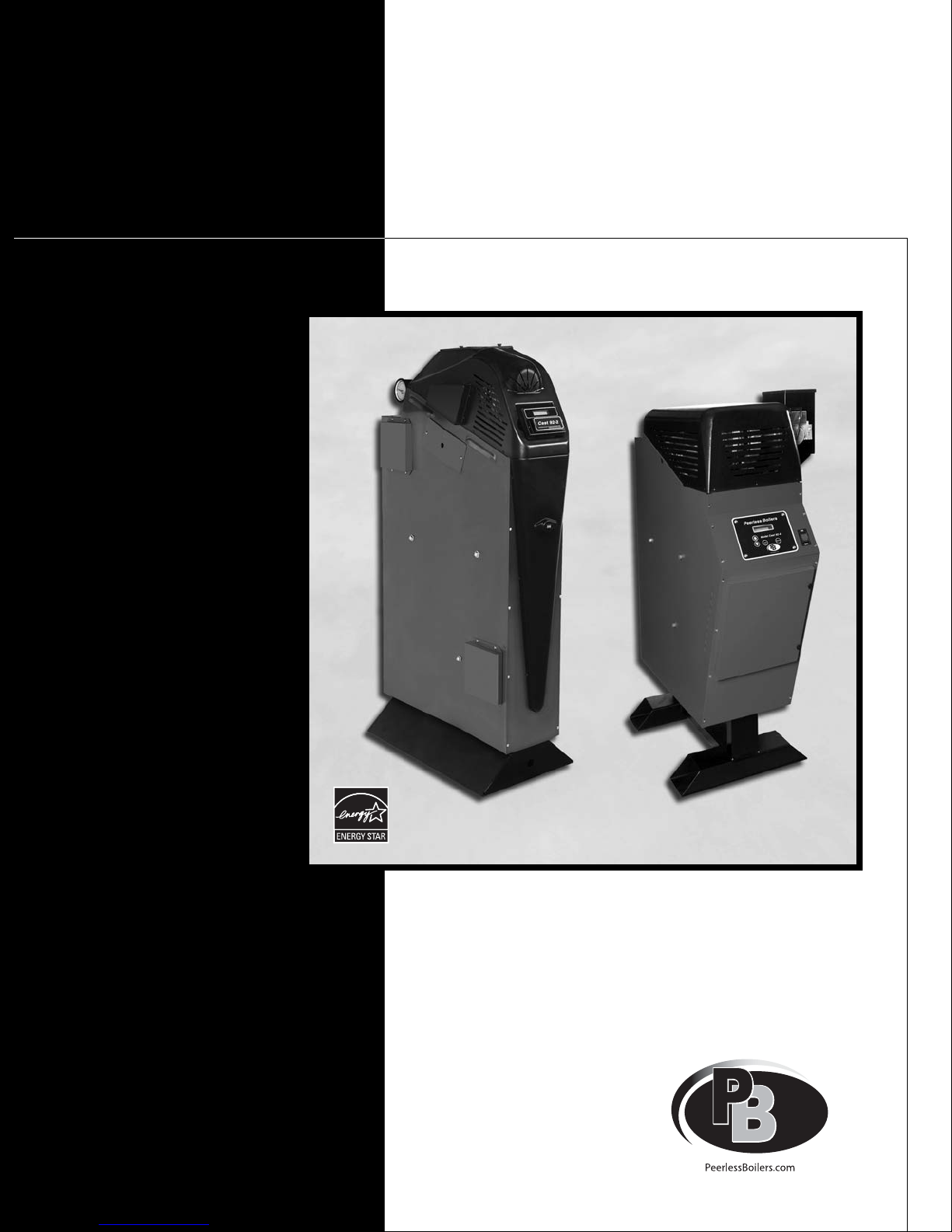
CAST 92
Boilers
Peerless
Gas
Installation,
Operation &
Maintenance
Manual
As an ENERGY STAR®Partner, PB Heat, LLC has determined that this
product meets the ENERGY STAR guidelines for energy efficiency.
Page 2

USING THIS MANUAL 1
A. INSTALLATION SEQUENCE . . . . . . . . . . . . .1
B. SPECIAL ATTENTION BOXES . . . . . . . . . . . .1
1. PREINSTALLATION 2
A. GENERAL . . . . . . . . . . . . . . . . . . . . . . . . . . . .2
B. CODES & REGULATIONS . . . . . . . . . . . . . . .2
C. BOILER LOCATION REQUIREMENTS . . . . . .3
D. CLEARANCE REQUIREMENTS . . . . . . . . . . .4
E. COMBUSTION AIR REQUIREMENTS . . . . . .4
2. BOILER SET-UP 7
A. REMOVE THE BOILER FROM THE CRATE . .7
B. INSTALL THE RELIEF VALVE . . . . . . . . . . . . .7
C. BOILER PIPING – GENERAL . . . . . . . . . . . . .7
3. VENTING & AIR INLET PIPING 9
A. COMMON VENT SYSTEMS . . . . . . . . . . . . .9
B. VENT AND AIR PIPING, GENERAL . . . . . . .10
C. VENT PIPING . . . . . . . . . . . . . . . . . . . . . . . .10
D. AIR PIPING . . . . . . . . . . . . . . . . . . . . . . . . . .10
E. TERMINATIONS . . . . . . . . . . . . . . . . . . . . . .10
F. VENT PIPED THROUGH THE ROOF
(COMBUSTION AIR FROM THE BOILER ROOM) . .10
G. VENT PIPED THROUGH THE ROOF
(AIR PIPED THROUGH SIDE WALL) . . . . . . . . . .11
H. VENT & AIR PIPED THROUGH THE ROOF
(SEPARATE VENT AND AIR TERMINATIONS) . . . .11
I. VENT PIPED THROUGH A SIDE WALL
(SEPARATE VENT AND AIR TERMINATIONS) . . . .12
J. VENT & AIR PIPED THROUGH A
SIDE WALL (SEPARATE VENT AND AIR
TERMINATIONS)
. . . . . . . . . . . . . . . . . . . . . . .12
K. VENT & AIR PIPED THROUGH A
SIDE WALL (CONCENTRIC VENT/AIR
TERMINATION)
. . . . . . . . . . . . . . . . . . . . . . . .13
3A. VENT & AIR PIPING: THROUGH THE ROOF
(COMBUSTION AIR FROM THE BOILER ROOM) 14
A. BOILER VENT CONNECTION . . . . . . . . . . .14
B. VENT PIPING COMPONENTS . . . . . . . . . . .15
C. SUPPORT THE VENT PIPING
COMPLETELY . . . . . . . . . . . . . . . . . . . . . . . .15
D. FLOOR AND WALL PENETRATIONS . . . . .15
E. ROOF PENETRATIONS . . . . . . . . . . . . . . . .15
F. RAIN CAP TERMINATION . . . . . . . . . . . . . .15
G. COMBUSTION AIR OPENINGS . . . . . . . . . .16
H. MULTIPLE BOILER INSTALLATIONS . . . . . .16
3B. VENT & AIR PIPING: THROUGH THE ROOF
(AIR PIPED THROUGH SIDE WALL) 17
A. BOILER VENT CONNECTION . . . . . . . . . . .17
B. VENT PIPING COMPONENTS . . . . . . . . . . .18
C. SUPPORT THE VENT PIPING
COMPLETELY . . . . . . . . . . . . . . . . . . . . . . . .18
D. FLOOR AND WALL PENETRATIONS . . . . .18
E. ROOF PENETRATIONS . . . . . . . . . . . . . . . .18
F. RAIN CAP TERMINATION . . . . . . . . . . . . . .18
G. AIR PIPE CONNECTION . . . . . . . . . . . . . . . .19
H. SUPPORTING AIR PIPING . . . . . . . . . . . . . .19
I. AIR PIPE TERMINATION . . . . . . . . . . . . . . .19
J. MULTIPLE BOILER INSTALLATIONS . . . . . .21
3C. VENT PIPING: THROUGH THE ROOF
(SEPARATE TERMINATIONS) 22
A. BOILER VENT CONNECTION . . . . . . . . . . .22
B. VENT PIPING COMPONENTS . . . . . . . . . . .23
C. SUPPORT THE VENT PIPING
COMPLETELY . . . . . . . . . . . . . . . . . . . . . . . .23
D. FLOOR AND WALL PENETRATIONS . . . . .23
E. ROOF PENETRATIONS . . . . . . . . . . . . . . . .23
F. RAIN CAP TERMINATION . . . . . . . . . . . . . .23
G. AIR PIPE CONNECTION . . . . . . . . . . . . . . . .24
H. SUPPORTING AIR PIPING . . . . . . . . . . . . . .24
I. AIR PIPE TERMINATION . . . . . . . . . . . . . . .24
J. MULTIPLE BOILER INSTALLATIONS . . . . . .25
3D. VENT & AIR PIPING: THROUGH A SIDE
WALL (COMBUSTION AIR FROM THE
BOILER ROOM) 26
A. BOILER VENT CONNECTION . . . . . . . . . . .26
B. VENT PIPING COMPONENTS . . . . . . . . . . .27
C. SUPPORT THE VENT PIPING
COMPLETELY . . . . . . . . . . . . . . . . . . . . . . . .27
D. SIDEWALL TERMINATION . . . . . . . . . . . . . .27
E. COMBUSTION AIR OPENINGS . . . . . . . . . .29
F. MULTIPLE BOILER INSTALLATIONS . . . . . .29
3E. VENT & AIR PIPING: THROUGH A SIDE
WALL (SEPARATE TERMINATIONS) 30
A. BOILER VENT CONNECTION . . . . . . . . . . .30
B. VENT PIPING COMPONENTS . . . . . . . . . . .31
C. SUPPORT THE VENT PIPING
COMPLETELY . . . . . . . . . . . . . . . . . . . . . . . .31
D. AIR PIPE CONNECTION . . . . . . . . . . . . . . . .31
E. SUPPORTING AIR PIPING . . . . . . . . . . . . . .32
F. SIDEWALL TERMINATION ASSEMBLIES . .32
G. MULTIPLE BOILER INSTALLATIONS . . . . . .34
TABLE OF CONTENTS
TABLE OF CONTENTS
Page 3

3F. VENT & AIR PIPING: THROUGH A SIDE
WALL (CONCENTRIC TERMINATION) 35
A. BOILER VENT CONNECTION . . . . . . . . . . .35
B. VENT PIPING COMPONENTS . . . . . . . . . . .36
C. SUPPORT THE VENT PIPING
COMPLETELY . . . . . . . . . . . . . . . . . . . . . . . .36
D. AIR PIPE CONNECTION . . . . . . . . . . . . . . . .36
E. SUPPORTING AIR PIPING . . . . . . . . . . . . . .37
F. SIDEWALL TERMINATION/CONCENTRIC
VENT-AIR ASSEMBLY . . . . . . . . . . . . . . . . .37
G. MULTIPLE BOILER INSTALLATIONS . . . . . .37
4. WATER PIPING & CONTROLS 39
A. BOILER PIPING CONNECTIONS . . . . . . . . .39
B. SYSTEM DESIGN . . . . . . . . . . . . . . . . . . . . .39
C. CIRCULATOR REQUIREMENTS . . . . . . . . . .39
D. ADDITIONAL CONTROLS . . . . . . . . . . . . . .40
E. EXPANSION TANK & AIR SEPARATION . . .40
F. ZONING WITH ZONE VALVES . . . . . . . . . .42
G. ZONING WITH CIRCULATORS . . . . . . . . . .43
H. MULTIPLE BOILERS,
PRIMARY/SECONDARY . . . . . . . . . . . . . . . .44
I. MULTIPLE BOILERS, PARALLEL FLOW . . .45
J. CHILLED WATER SYSTEMS . . . . . . . . . . . .46
5. FUEL PIPING 47
A. CHECK THE GAS TYPE . . . . . . . . . . . . . . . .47
B. GAS SUPPLY COMPONENTS . . . . . . . . . . .47
C. GAS PIPING JOINTS . . . . . . . . . . . . . . . . . .48
D. GAS PIPE SIZING . . . . . . . . . . . . . . . . . . . . .48
E. TEST ALL GAS PIPING FOR LEAKS . . . . . .48
6. CONDENSATE DRAIN PIPING 49
A. FILL THE CONDENSATE TRAP . . . . . . . . . .49
B. CONDENSATE LINE INSTALLATION . . . . . .49
C. CONDENSATE LINE REQUIREMENTS . . . .49
7. ELECTRICAL CONNECTIONS 50
A. GENERAL . . . . . . . . . . . . . . . . . . . . . . . . . . .50
B. POWER SUPPLY (120 VAC) . . . . . . . . . . . . .50
C. CIRCULATOR WIRING . . . . . . . . . . . . . . . . .50
D. SENSOR WIRING . . . . . . . . . . . . . . . . . . . . .51
E. IAR (INDOOR AIR RESET) WIRING,
WHEN USED . . . . . . . . . . . . . . . . . . . . . . . .52
F. DHW WIRING . . . . . . . . . . . . . . . . . . . . . . . .52
8. BOILER CONTROL: OPERATION 55
A. THE CAST 92 BOILER CONTROL . . . . . . . .55
B. BEFORE CONTROL SETUP . . . . . . . . . . . . .56
C. THE CONTROL DISPLAY . . . . . . . . . . . . . . .56
D. RECOMMENDED SETTINGS . . . . . . . . . . . .57
E. ADJUST SETPOINTS . . . . . . . . . . . . . . . . . .57
F. INDOOR AIR . . . . . . . . . . . . . . . . . . . . . . . . .58
G. OUTDOOR AIR . . . . . . . . . . . . . . . . . . . . . . .58
H. SET THE SYSTEM CLOCK . . . . . . . . . . . . . .59
9. BOILER CONTROL: MULTIPLE
BOILERS OVERVIEW 66
9A. MULTIPLE BOILERS – CAST 92 CONTROL 66
9B MULTIPLE BOILERS – (BMS) . . . . . . . . . . . .66
9C MULTIPLE BOILERS – EXTERNAL 4-20MA
CONTROL . . . . . . . . . . . . . . . . . . . . . . . . . . .66
9A. BOILER CONTROL: MULTIPLE
BOILERS (CAST 92 CONTROL) 67
A. OVERVIEW: CONTROL SETUP
SEQUENCE . . . . . . . . . . . . . . . . . . . . . . . . . .67
B. POWER SUPPLY (120 VAC) . . . . . . . . . . . . .67
C. CIRCULATOR WIRING . . . . . . . . . . . . . . . . .67
D. IAR (INDOOR AIR RESET) WIRING,
WHEN USED . . . . . . . . . . . . . . . . . . . . . . . .68
E. SENSOR WIRING . . . . . . . . . . . . . . . . . . . . .69
F. DHW WIRING . . . . . . . . . . . . . . . . . . . . . . . .69
G. EXTERNAL INTERLOCKS . . . . . . . . . . . . . .72
H. OVERRIDES – CONTROL PRIORITIES . . . . .72
I. SET TERMINATION DIP SWITCHES . . . . . .72
J. SET CONTROL PARAMETERS ON
KEYPADS . . . . . . . . . . . . . . . . . . . . . . . . . . .73
K. START-UP BOILERS
L. CONNECT NETWORK CABLES . . . . . . . . . .73
M. MASTER BOILER CABLE . . . . . . . . . . . . . . .73
N. MEMBER BOILER CABLES . . . . . . . . . . . . .74
O. CHECK THE NETWORK . . . . . . . . . . . . . . . .74
P. START THE SYSTEM . . . . . . . . . . . . . . . . . .74
9B. BOILER CONTROL: MULTIPLE
BOILERS BUILDING MANAGEMENT
CONTROL (BMS) 75
A. OVERVIEW . . . . . . . . . . . . . . . . . . . . . . . . . .75
B. MODBUS REGISTERS . . . . . . . . . . . . . . . . .75
C. BACNET OR LONWORKS PROTOCOLS . . .76
D. WIRING AND SET-UP . . . . . . . . . . . . . . . . .76
E. CONNECT THE BMS CABLE . . . . . . . . . . . .76
F. VERIFY BMS/HEATNET OPERATION . . . . .76
9C. BOILER CONTROL: MULTIPLE BOILERS
EXTERNAL 4–20MA CONTROL 77
A. OVERVIEW — CONTROL SETUP
SEQUENCE . . . . . . . . . . . . . . . . . . . . . . . . . .77
B. CONNECT 4-20MA WIRING . . . . . . . . . . . .77
C. POWER SUPPLY (120 VAC) . . . . . . . . . . . . .77
D. CIRCULATOR WIRING . . . . . . . . . . . . . . . . .77
E. 4-20MA OPERATION . . . . . . . . . . . . . . . . . .79
F. IAR (INDOOR AIR RESET) WIRING –
APPLY ONLY IF USING SPACE HEATING
OVERRIDE MODE . . . . . . . . . . . . . . . . . . . .79
G. SENSOR WIRING . . . . . . . . . . . . . . . . . . . . .79
H. DHW WIRING – ONLY IF USING DHW
OVERRIDE MODE . . . . . . . . . . . . . . . . . . . .79
I. OVERRIDES – CONTROL PRIORITIES . . . . .79
TABLE OF CONTENTS
Page 4

J. SET CONTROL PARAMETERS ON
KEYPADS . . . . . . . . . . . . . . . . . . . . . . . . . . .82
K. START-UP BOILERS . . . . . . . . . . . . . . . . . . .82
L. START THE SYSTEM . . . . . . . . . . . . . . . . . .82
10. FILL AND TEST THE SYSTEM 83
A. CLOSED SYSTEMS ONLY . . . . . . . . . . . . . .83
B. HARD WATER CONDITIONS . . . . . . . . . . . .83
C. PREVENT OXYGEN CORROSION . . . . . . . .83
D. FLUSH AND CLEAN THE SYSTEM . . . . . . .83
E. PURGE AIR FROM THE SYSTEM . . . . . . . .83
F. ADD A CHEMICAL INHIBITOR . . . . . . . . . . .83
G. WATER PH . . . . . . . . . . . . . . . . . . . . . . . . . .84
H. ANTIFREEZE . . . . . . . . . . . . . . . . . . . . . . . . .84
I. SYSTEM PRESSURE . . . . . . . . . . . . . . . . . .84
J. FINAL CHECKS . . . . . . . . . . . . . . . . . . . . . . .85
11. START-UP PROCEDURE 86
A. START-UP CHECKLIST . . . . . . . . . . . . . . . . .86
B. LIGHTING & OPERATING PROCEDURES . .89
C. TURN THE BOILER OFF . . . . . . . . . . . . . . . .90
D. CHECK IGNITION . . . . . . . . . . . . . . . . . . . . .90
E. INSERT COMBUSTION ANALYZER
PROBE . . . . . . . . . . . . . . . . . . . . . . . . . . . . .90
F. CHECK HIGH FIRE OPERATION . . . . . . . . .90
G. ADJUST GAS VALVE THROTTLE
SETTING . . . . . . . . . . . . . . . . . . . . . . . . . . . .91
H. VERIFY GAS INLET PRESSURE . . . . . . . . .91
I. TO METER GAS INPUT (NATURAL
GAS ONLY) . . . . . . . . . . . . . . . . . . . . . . . . . .92
J. CHECK LOW FIRE OPERATION . . . . . . . . . .92
K. WHEN IS LOW FIRE ADJUSTMENT
REQUIRED? . . . . . . . . . . . . . . . . . . . . . . . . .92
L. REMOVING THE BOILER JACKET TOP . . . .92
M. ADJUSTING THE LOW-FIRE SETTING . . . .93
N. REPLACE THE BOILER JACKET TOP . . . . .93
O. MEASURE FLAME CURRENT . . . . . . . . . . .93
P. CHECK BOILER MODULATION . . . . . . . . . .93
Q. TEST FLAME FAILURE MODES . . . . . . . . .94
R. TEST CONTROL & INTERLOCK
OPERATION . . . . . . . . . . . . . . . . . . . . . . . . .94
S. FILL OUT THE COMBUSTION TEST
RECORD . . . . . . . . . . . . . . . . . . . . . . . . . . . .94
12. TROUBLESHOOTING 95
13. MAINTENANCE 97
A. READ BEFORE PROCEEDING . . . . . . . . . . .97
B. HANDLING CERAMIC FIBER AND
FIBERGLASS MATERIALS . . . . . . . . . . . . . .97
C. CLEANING THE AIR FILTER . . . . . . . . . . . . .97
D. ACCESSING THE ELECTRODE
ASSEMBLY . . . . . . . . . . . . . . . . . . . . . . . . . .98
E. ACCESSING THE BURNER . . . . . . . . . . . . .99
F. ANNUAL START-UP OVERVIEW . . . . . . . .100
G. ANNUAL START-UP CHECKLIST . . . . . . . .100
14. REPAIR PARTS 102
15.BOILER RATINGS & SPECIFICATIONS 108
APPENDIX A. SUGGESTED WIRING 109
IAR (INDOOR AIR RESET) WIRING, WHEN
USED WIRING FOR 3-WIRE ZONE VALVES
WITHOUT A ZONE CONTROLLER . . . . . . . . .109
IAR (INDOOR AIR RESET) WIRING, WHEN
USED WIRING FOR CIRCULATOR RELAYS
(RELAYS MUST HAVE 24VAC COMMON
TERMINALS) . . . . . . . . . . . . . . . . . . . . . . . . . .110
IAR (INDOOR AIR RESET) WIRING, WHEN
USED WIRING FOR TYPICAL ZONE
CONTROLLER . . . . . . . . . . . . . . . . . . . . . . . . .111
APPENDIX B. COMBUSTION TEST
RECORD 113
TABLE OF CONTENTS
Page 5
1
A. INSTALLATION SEQUENCE
Follow the installation instructions provided in this manual
in the order shown. The order of these instructions has
been set in order to provide the installer with a logical
sequence of steps that will minimize potential
interferences and maximize safety during boiler
installation.
B. SPECIAL ATTENTION BOXES
Throughout this manual special attention boxes are
provided to supplement the instructions and make special
notice of potential hazards. The definition of each of
these categories, in the judgement of PB Heat, LLC
are as follows:
USING THIS MANUAL
Indicates special attention is needed, but not directly
related to potential personal injury or property
damage.
NOTICE
Indicates a condition or hazard which will or can
cause minor personal injury or property damage.
CAUTION
DANGER
Indicates a condition or hazard which will cause
severe personal injury, death or major property
damage.
Indicates a condition or hazard which may cause
severe personal injury, death or major property
damage.
WARNING
USING THIS MANUAL
Page 6
2
PREINSTALLATION
A. GENERAL
1. Cast 92 boilers are supplied completely assembled as
packaged boilers. The package should be inspected
for damage upon receipt and any damage to the unit
should be reported to the shipping company and
wholesaler. This boiler should be stored in a clean, dry
area.
2. Carefully read these instructions and be sure to
understand the function of all connections prior to
beginning installation. Contact your PB Heat, LLC
Representative for help in answering questions.
3. This boiler must be installed by a qualified contractor.
The boiler warranty may be voided if the boiler is not
installed correctly.
4. A hot water boiler installed above radiation or as
required by the Authority having jurisdiction, must be
provided with a low water fuel cut-off device either as
part of the boiler or at the time of installation.
B. CODES & REGULATIONS
1. Installation and repairs are to be performed in strict
accordance with the requirements of state and local
regulating agencies and codes dealing with boiler and
gas appliance installation.
2. In the absence of local requirements the following
should be followed:
a. ASME Boiler and Pressure Vessel Code, Section
IV - “Heating Boilers”
b. ASME Boiler and Pressure Vessel Code, Section
VI - “Recommended Rules for the Care and
Operation of Heating Boilers”
c. ANSI Z223.1/NFPA 54 - “National Fuel Gas Code”
d. ANSI/NFPA 70 - “National Electrical Code”
e. ANSI/NFPA 211 - “Chimneys, Fireplaces, Vents
and Solid Fuel Burning Appliances”
3. Where required by the authority having jurisdiction,
the installation must conform to the Standard for
Controls and Safety Devices for Automatically Fired
Boilers, ANSI/ASME CSD-1.
**Please read if installing in Massachusetts**
Massachusetts requires manufacturers of Side Wall
Vented boilers to provide the following information
from the Massachusetts code:
·
A hard wired carbon monoxide detector with an
alarm and battery back-up must be installed on
the floor level where the gas equipment is to be
installed AND on each additional level of the
dwelling, building or structure served by the side
wall horizontal vented gas fueled equipment.
·
In the event that the side wall horizontally vented
gas fueled equipment is installed in a crawl space
or an attic, the hard wired carbon monoxide
detector with alarm and battery back-up may be
installed on the next adjacent floor level.
·
Detector(s) must be installed by qualified licensed
professionals.
·
APPROVED CARBON MONOXIDE
DETECTORS: Each carbon monoxide detector
shall comply with NFPA 720 and be ANSI/UL
2034 listed and IAS certified.
·
SIGNAGE: A metal or plastic identification plate
shall be permanently mounted to the exterior of
the building at a minimum height of eight (8) feet
above grade directly in line with the exhaust vent
terminal for the horizontally vented gas fueled
heating appliance or equipment. The sign shall
read, in print size no less than one-half (1/2) inch
in size, “GAS VENT DIRECTLY BELOW.
KEEP CLEAR OF ALL OBSTRUCTIONS”.
·
EXEMPTIONS to the requirements listed above:
°
The above requirements do not apply if the
exhaust vent termination is seven (7) feet or
more above finished grade in the area of the
venting, including but not limited to decks and
porches.
°
The above requirements do not apply to a
boiler installed in a room or structure separate
from the dwelling, building or structure used in
whole or in part for residential purposes.
·
This boiler installation manual shall remain with
the boiler at the completion of the installation.
See the latest edition of Massachusetts Code 248 CMR
for complete verbage and also for additional (non-vent
related) requirements (248 CMR is available online).
If your installation is NOT in Massachusetts, please
see your authority of jurisdiction for requirements that
may be in effect in your area. In the absence of such
requirements, follow the National Fuel Gas Code,
ANSI Z223.1/NFPA 54 and/or CAN/CSA B149.1,
Natural Gas and Propane Installation Code.
1. PREINSTALLATION
Liquefied Petroleum (LP) Gas or Propane is heavier
than air and, in the event of a leak, may collect in low
areas such as basements or floor drains. The gas
may then ignite resulting in a fire or explosion.
WARNING
Page 7

3
C. BOILER LOCATION REQUIREMENTS
1. Indoor Installation Only:
a. Do not install the boiler outside or in an area that
would expose the boiler or its gas or electrical
components to rain or dripping or spraying water.
b. Do not install the boiler in a location that would
subject the boiler to freezing. Where freeze
protection is needed, follow the guidelines in this
manual.
2. Flooring:
a. The boiler can be installed on combustible
flooring, but must not be installed on carpeting.
b. The floor must be structurally sound and capable
of supporting the weight of the boiler.
c. The boiler must be leveled front to back and side
to side. Use metal shims if necessary.
3. Accessibility:
Jacket parts will have to be removed for some service
procedures. Ensure that the location provides a
reasonable means for service and operation of the
boiler.
4. System Piping, Fuel and Electrical Supply:
a. The boiler must be located such that piping for
water, gas, vent and air can reasonable be
connected.
b. There must be a reasonable means of providing
electrical supply to the boiler.
5. Adjacent Construction:
Locate the boiler in an area that will prevent water
damage to adjacent construction should a leak occur
or during routine maintenance.
6. Combustion Air:
a. Do not place the boiler in a location that would
restrict the flow of combustion air into the air
intake or subject the boiler to a negative air
pressure in the space when using air from the
boiler room.
b. Provide required combustion air openings to the
boiler room and the building (when required)
when using air from the boiler room for
combustion (see Section C, “Combustion Air
Requirements”). If air is piped to the boiler air
intake connection, combustion air openings are
not required unless other appliances share the
same room.
c. Buildings will require the installation of a fresh air
duct or other means of providing make-up air if
the intake air option isn't used. Any building
utilizing other gas burning appliances, a fireplace,
wood stove or any type of exhaust fan must be
checked for adequate combustion air when all of
these devices are in operation at one time. Sizing
of an outside air duct must be done to meet the
requirements of all such devices.
d. The boiler must be supplied with combustion air
in accordance with Section 5.3, "Air for
Combustion and Ventilation," of the latest revision
of the National Fuel Gas Code, ANSI
Z223.1/NFPA 54 and all applicable local building
codes. Canadian installations must comply with
CSA B149.1 or .2 Installation Code for Gas
Burning Appliances and Equipment, or applicable
provisions of the local building codes.
7. Negative Room Pressure:
Never operate the boiler in an environment subjected
to a negative pressure unless it is Direct Vented.
Failure to comply with this warning can result in
excessive levels of carbon monoxide.
8. Combustion Air Contamination:
a. Combustion air contaminated with fluorocarbons
or other halogenated compounds such as cleaning
solvents and refrigerants will result in the
formation of acids in the combustion chamber.
These acids will cause premature failure of the
boiler.
b. Construction Dust
: If the boiler is operated while
the building is under construction it must be
protected from wood, concrete, sheet rock and
other types of dust. Failure to properly protect the
boiler from construction dust will damage the
boiler.
c. If the boiler has been operated with contaminated
air, it must be thoroughly inspected. Where
possible, boiler components must be cleaned,
following instructions provided in this manual
and/or supplementary instructions from PB Heat.
Where cleaning is not possible, the boiler may
have to be replaced.
d. Never store combustible materials, gasoline or any
product containing flammable vapors or liquids in
the vicinity of the boiler.
9. Clearances:
a. All installations must provide the minimum
clearances to combustible materials given in
Section B, “Clearance Requirements”.
b. The installation should provide the minimum
service clearances given in Section B, “Clearance
Requirements”, when possible. If these clearances
cannot be met, then:
Ensure that boiler components can be
accessed for operation/start-up/maintenance as
required in this manual.
PREINSTALLATION
Do not install the boiler unless the location meets all
of the requirements in Sections 1 through 9 below.
Failure to comply could result in severe personal
injury, death or substantial property damage.
WARNING
Page 8
4
PREINSTALLATION
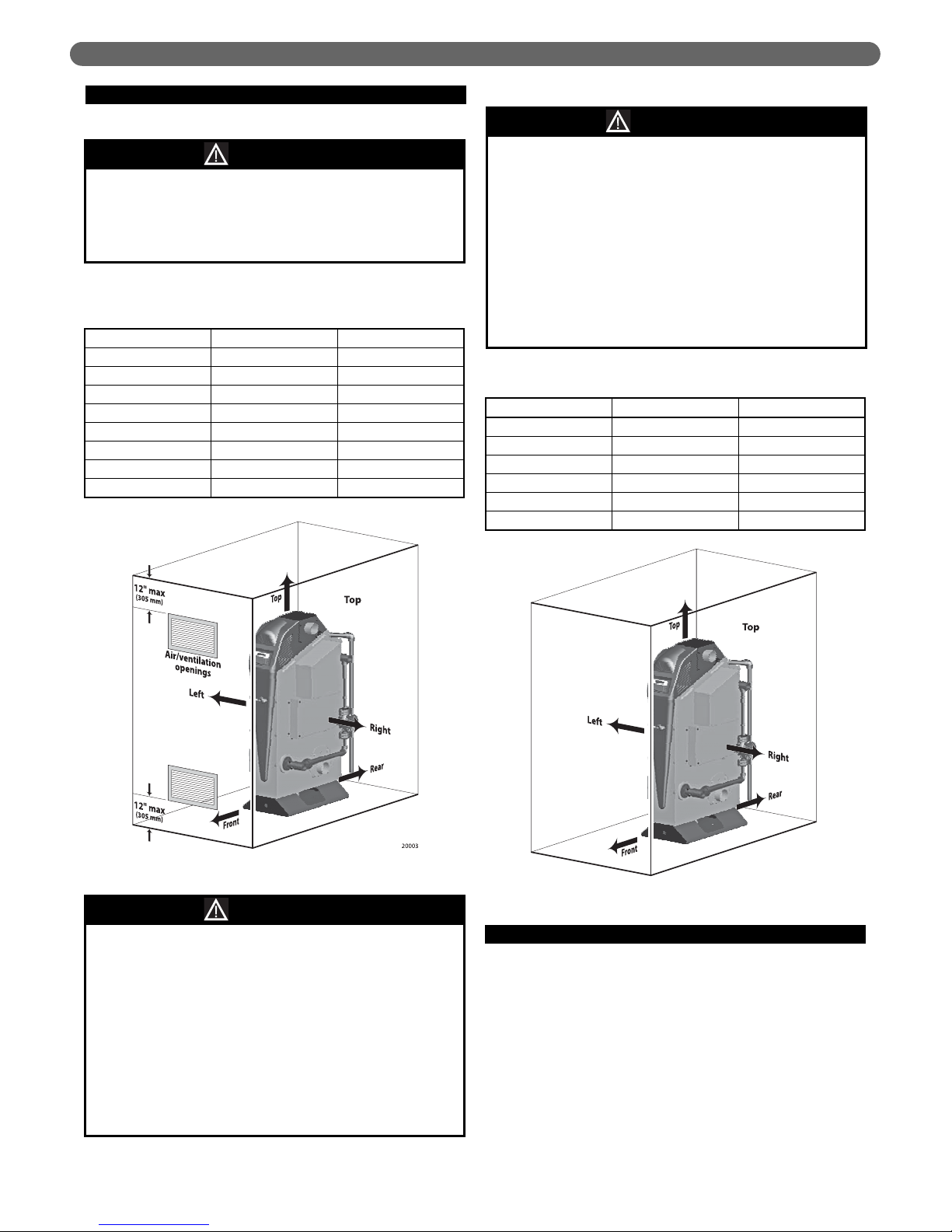
D. CLEARANCE REQUIREMENTS
1. Clearances to Combustible Surfaces:
2. Clearances for Service and Operation:
E. COMBUSTION AIR REQUIREMENTS
1. Air Ducted to Boiler Air Intake:
a. If air is ducted from outside to the boiler air
intake, follow instructions in Section 3, “Venting &
Air Inlet Piping”.
b. If the boiler is located in a small room (clearances
less than the recommended SERVICE/OPERATION
clearances given in Figure 1.2):
All installations must provide the minimum
clearances to combustible materials and surfaces
given in Table 1.1. Failure to comply could result in a
fire hazard, causing severe personal injury, death or
substantial property damage.
WARNING
Table 1.1: Minimum Clearances to Combustible
Materials/Surfaces for ALL Installations
(Figure 1.1)
From Inches Millimeters
To p 6 153
Back 6 153
Left side 6 153
Right side 6 153
Front 6 153
Rear 6 153
Vent piping 2 51
System water piping 1 25.4
If the boiler is located in a closed room, the room
must be provided with ventilation openings even if
air is ducted to the boiler. See Figure 1.1. Size the
openings with a free area no less than 1 square inch
per BTUH input of all Cast 92 boilers in the room.
EXCEPTION: Ventilation openings are not required if
the boiler room provides at least the minimum
SERVICE/OPERATION clearances given in Table 1.2.
Failure to provide adequate ventilation could result
in overheating of the boiler components or the
room, potentially causing severe personal injury,
death or substantial property damage.
WARNING
The installation must provide reasonable access and
clearance for service and operation of the boiler. Table
2 gives recommended minimum clearances for
service and operation. The boiler may be installed in a
space that does not provide these recommended
clearances provided it is accessible for the service
and operation procedures required in this manual.
Flame observation port — The flame observation
port on the LEFT side of the boiler must be
accessible to view the combustion chamber during
boiler start-up. Make sure that the installation allows
serviceman access to the left side for this purpose.
WARNING
Table 1.2: Recommended Minimum Clearances for
Service/Operation (Figure 1.2)
From Inches Millimeters
To p 24 610
Back 24 610
Left side 24 610
Right side 24 610
Front 36 914
Rear 18 457
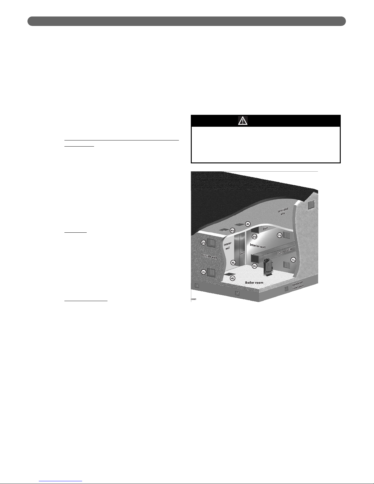
Figure 1.1: Clearance to Combustibles Materials
Figure 1.2: Service/Operation Clearance References
Page 9
5
PREINSTALLATION
i. No Other Appliances in the Room: Provide
two ventilation openings through one of the
enclosure walls. Each opening must be sized
for a free area of at least 1 square inch per
1,000 BTUH input of the Cast 92 boilers in
the room. One opening must be within 12
inches of the ceiling, the other within 12
inches of the floor.
ii. Other Appliances in the Same Room: The room
must have combustion air openings sized for
the other appliances. Increase the free area of
the air openings by one square inch per 1,000
BTUH of the Cast 92 boilers located in the
room.
2. Air From Boiler Room:
When the Boiler Draws Combustion Air from the
Boiler Room:
i. If the room volume is at least 50 cubic feet per
BTUH of the combined input of all appliances
in the room, no special openings are needed
UNLESS the building is of tight construction
(see definition). If the building is of tight
construction, provide openings to the building
in accordance with all applicable codes.
ii. If the boiler is in a space smaller than 50 cubic
feet volume per BTUH input, provide air
openings using one of the methods in Figure 1.3.
3. Definitions:
a. Free Area
: Louvers or grilles reduce the area of an
opening. Free area is the area remaining with the
louver or grille in place. If the free area of a louver
is unknown, use the following:
i. Metal Louver: Multiply required free area of
the opening times 1.7 to determine actual area
of the required opening.
ii. Wood Louver: Multiply required free area of
the opening times 5 to determine actual area
of the required opening.
b. Tight Construction
: When a building is extensively
sealed to prevent air infiltration, it cannot provide
enough air for combustion unless openings are
provided to the outside. The National Fuel Gas
Code defines such buildings as having all of the
following:
i. Walls and ceilings exposed to the outside
atmosphere have a continuous water vapor
retarder with a rating of 1 perm or less with
openings gasketed.
ii. Weather-stripping has been added on
openable windows and doors.
iii. Caulking or sealants are applied to areas such
as joints around windows and door frames,
between sole plates and floors, between wallceiling joints, between wall panels, at
penetrations for plumbing, electrical, and gas
lines, and in other openings.
4. Conversion Factors:
In
2
/1,000 BTUH to cm2/kw — Multiply In2/1,000
BTUH times 22
In
2
/2,000 BTUH to cm2/kw — Multiply In2/2,000
BTUH times 11
In
2
/3,000 BTUH to cm2/kw — Multiply In2/3,000
BTUH times 7.4
In
2
/4,000 BTUH to cm2/kw — Multiply In2/4,000
BTUH times 5.5
5. Air Opening Options for Combustion Air
Drawn from Boiler Room:
Upper openings (U) must be within 12 inches of the
ceiling. Lower openings (L) must be within 12 inches
of the floor.
Option 1 – Air Openings Through Interior Wall:
When air is supplied to the boiler room through
openings in an interior wall (air supply from inside the
building), size each opening to provide minimum free
area of:
1 in
2
per 1,000 BTUH of all Cast 92 boilers in the
room.
Figure 1.3: Air opening options for combustion air
drawn from boiler room
If other appliances are located in the same room as
the boiler, increase the size of air openings to
provide the free area required for the other
appliances in addition to the air required for the Cast
92 boiler(s).
WARNING
Page 10

6
PREINSTALLATION
Option 2 – Air Openings Through Outside Wall:
When air is supplied to the boiler room through
openings in an outside wall (air supply from outside
the building), size each opening to provide minimum
free area of:
1 in
2
per 4,000 BTUH of all Cast 92 boilers in the
room.
Option 3 – Horizontal Ducts to Outside Wall:
When air is supplied to the boiler room through
horizontal ducts to an outside wall (air supply from
outside the building), size each opening to provide
minimum free area of:
1 in
2
per 3,000 BTUH of all Cast 92 boilers in the
room.
Option 4 – Openings to Attic/Crawl Space:
Air openings can be connected to a ventilated attic or
crawl space. The upper opening must be to the attic.
The lower opening can be a vertical duct from the
attic or an opening in the floor from the crawl space.
Size each opening to provide minimum free area of:
1 in
2
per 3,000 BTUH of all Cast 92 boilers in the
room.
Option 5 – Single Opening (not shown):
A single opening directly connected to the outdoors
through a wall or a vertical or horizontal duct can be
used if the installation provides the clearances of
Figure 1.2, and the top of the opening is within 12
inches of the ceiling. Size the opening to provide
minimum free area of:
1 in
2
per 3,000 BTUH of all Cast 92 boilers in the
room.
Page 11

7
A. REMOVE THE BOILER FROM THE CRATE
1. Remove the crate from the skid. But leave the boiler
on the skid to move the boiler near its location.
2. Inspect the boiler thoroughly for any possible damage
that may have occurred in shipping or handling.
3. Slide the boiler off of the skid into position.
4. Use a spirit level to check whether the boiler sides and
front are vertically plumb. If not, slide metal shims
under the base until the boiler is level.
B. INSTALL THE RELIEF VALVE
Check Relief Valve Pressure Setting:
Inspect the boiler relief valve before installing to ensure it
is set at the pressure required for the system. You should
also verify that all water system components are rated for
at least the pressure setting of the relief valve to avoid
component damage due to excess pressure.
2. Connecting the Relief Valve:
Connect 3/4" NPT black iron pipe and fitting so the
relief valve as shown in Figure 2.1. Follow all
instructions provided in the relief valve manufacturer’s
instructions and labeling.
C. BOILER PIPING — GENERAL
Piping Guidelines:
• All installations must be installed by a qualified technician
in accordance with the latest revision of the ANSI/ASME
Boiler and Pressure Vessel Code, Section IV.
• Where required, the installation must comply with
ANSI/ASME CSD-1, Standard for Controls and Safety
Devices for Automatically Fired Boilers.
2. BOILER SET-UP
Never install any type of valve between the boiler and
the relief valve, or in the relief discharge piping. An
explosion could occur, causing severe personal
injury, death or substantial property damage. General
piping requirements.
WARNING
Improper piping of the boiler will void the
manufacturer’s warranty, and can cause boiler failure,
resulting in possible severe personal injury, death or
substantial property damage.
WARNING
Figure 2.1: Relief valve piping
Cold weather handling — The boiler jacket includes
plastic parts. If the boiler has been in a cold
environment (below 0°F), allow the boiler to warm to
room temperature before handling.
CAUTION
Do not drop the boiler or allow the jacket to bump
against the floor or wall when handling.
CAUTION
The boiler maximum allowable working pressure is
100 psig (700 kPa). The relief valve must never have a
setting greater than 100 psig. Using a higher pressure
relief valve could result in an explosion, causing
possible severe personal injury, death or substantial
property damage.
WARNING
Install a shut-off valve in the boiler supply and return
connections to allow isolation of the boiler for
servicing when necessary.
NOTICE
BOILER SET-UP
Page 12

8
• All applicable local codes and ordinances must also be
followed.
• A minimum clearance of 1" (25 mm) must be
maintained between heating system pipes and all
combustible construction.
• All heating system piping must be supported by
suitable hangers — not by the boiler.
• The thermal expansion of the system must be
considered when supporting the system.
• A minimum system pressure of 12 psig (84 kPa) must
be maintained.
BOILER SET-UP
Page 13
9
When a Cast 92 boiler replaces a boiler that shared a
common vent system, follow the guidelines below to
check operation of the remaining appliance(s).
A. COMMON VENT SYSTEMS
If an existing boiler is removed from a common venting
system, the common venting system may then be too
large for the proper venting of the remaining appliances
connected to it. At the time of removal of an existing
boiler, the following steps shall be followed with each
appliance remaining connected to the common venting
system placed in operation, while the other appliances
remaining connected to the common venting system are
not in operation.
1. Seal any unused openings in the common venting
system.
2. Visually inspect the venting system for proper size and
horizontal pitch and determine there is no blockage or
restriction, leakage, corrosion and other deficiencies
which could cause an unsafe condition.
3. Insofar as is practical, close all building doors and
windows and all doors between the space in which
the appliances remaining connected to the common
venting system are located and other spaces of the
building. Turn on clothes dryers and any appliance
not connected to the common venting system. Turn
on any exhaust fans, such as range hoods and
bathroom exhaust, so they will operate at maximum
speed. Do not operate a summer exhaust fan for a
boiler installation. Close fireplace dampers.
4. Place in operation the appliance being inspected.
Follow the lighting instructions. Adjust thermostat so
appliance will operate continuously.
5. Test for spillage at the draft hood relief opening after 5
minutes of main burner operation. Use the flame of a
match or candle, or smoke from a cigarette, cigar or
pipe.
6. After it has been determined that each appliance
remaining connected to the common venting system
properly vents when tested as outlined above, return
doors, windows, exhaust fans, fireplace dampers and
any other gas-burning appliance to their previous
condition of use.
3. VENTING & AIR INLET PIPING
DO NOT install a Cast 92 boiler on a common vent
system. All Cast 92 boilers must be individually
vented. Failure to comply could result in improper
operation of any of the appliances on the vent
system, resulting in possible severe personal injury,
death or substantial property damage.
WARNING
VENTING & AIR INLET PIPING
Heat-fab EZ Seal Joint Assembly
Page 14
10
7. Any improper operation of the common venting
system should be corrected so the installation
conforms with the National Fuel Gas Code, ANSI
Z223.1/NFPA 54. When resizing any portion of the
common venting system, the common venting system
should be resized to approach the minimum size as
determined using the appropriate tables in Appendix
F in the National Fuel Gas Code, ANSI Z223.1/ NFPA
54 and or CSA B149 Installation Codes.
B. VENT AND AIR PIPING, GENERAL
1. Pages 9 through 13 are a brief overview of the
options for vent and air piping configurations and give
a summary and brief list of requirements for each of
the vent/air configuration options.
2. When air is taken from the boiler room (no air pipe
connected to the boiler air inlet fitting), follow the
instructions in this manual to ensure the boiler room
has proper openings for combustion air and
ventilation.
C. VENT PIPING
1. Category II & IV Venting Only:
All Cast 92 boilers require vent piping listed for use in
pressurized, condensing operation. Use only the
materials specified in this manual. When venting
category II the flue pipe must be increased to 5 inch
for the 92-2 and 6 inch for the 92-4.
2. Vent Pipe Options:
Use only Heat-fab Saf-T Vent
®
EZ Seal or Z-Flex
®
Z-Vent vent pipe and components. You will find
specific component information for each configuration
in this manual.
3. Vent Pipe Joint Assembly:
EZ Seal and Z-Vent vent piping use a silicon rubber
ring-style gasket in each joint. Joints are secured using
metal tabs that wrap around a ring on the adjacent
piping component for Heat-fab vent pipe, or gear
clamps for Z-Flex vent pipe. Never use screws in the
vent piping. Screws are only applied to the air piping
portion of Heat-fab SC concentric vent, used for
concentric vent/air sidewall terminations.
D. AIR PIPING
1. Air Options:
Combustion air can be piped through the side wall or
through the roof of the building. Sidewall air intake
can be done with either through-the-roof or sidewall
venting.
2. Air Piping Materials:
The best choices for air piping are PVC, CPVC or
ABS. These materials are easy to work with and yield
a clean final appearance. Joint sealing is easier than
other methods because it only requires use of the
standard joint sealant for the type of plastic pipe used.
And there are not horizontal seams requiring sealing
like on metal air piping.
Other materials suitable for combustion air venting are
galvanized pipe, aluminum pipe and flexible
aluminum pipe. All joints, including the seams, of
these piping materials must be sealed with silicone
adhesive sealant, such as Dow Corning 732.
E. TERMINATIONS
1. Through-the-roof Terminations:
Both vent and air piping must terminate with a Heatfab or Z-Flex rain cap.
2. Sidewall Terminations:
Vent and air pipes can be individually terminated
using Heat-fab or Z-Flex termination elbows with
built-in screen, or concentrically terminated using
Heat-fab type SC concentric vent/air pipe (only when
using Heat-fab vent piping) Termination components
as given in this manual.
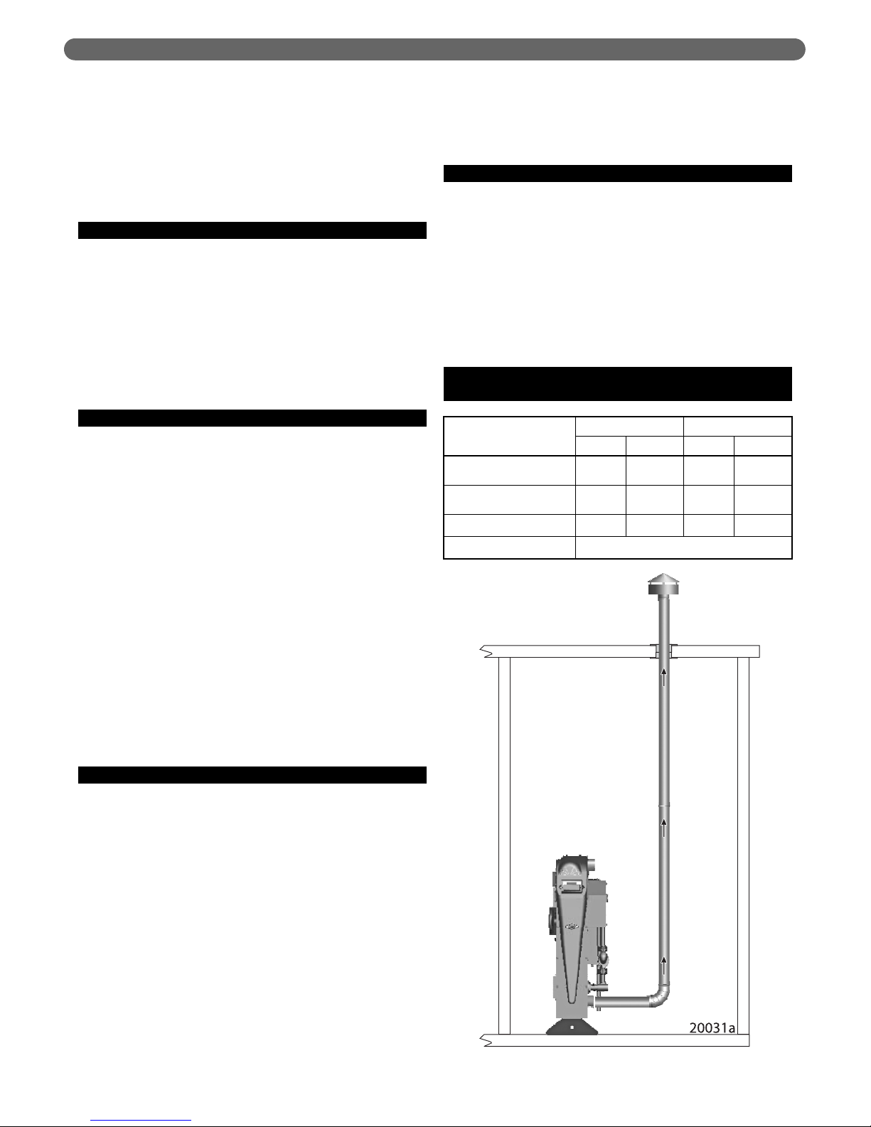
F. VENT PIPED THROUGH THE ROOF
(COMBUSTION AIR FROM THE BOILER ROOM)
VENTING & AIR INLET PIPING
Vent Components
92-2 92-4
Heat-Fab Z-Flex Heat-Fab Z-Flex
Vent Piping/Components
(Incl. Supports, Thimbles, etc.)
EZ-Seal3"Z-Vent3"EZ-Seal4"Z-Vent
4"
Boiler Adapter (Adapts from
EZ-Seal to Z-Vent Piping)
Not
Required
2SVSHTA03
Not
Required
2SVSHTA04
Rain Cap Vent Termination 5300CI 2SVSRCF03 5400CI 2SVSRCF04
Joint Sealant, as Needed GE RTV106 or Equivalent
Page 15
11
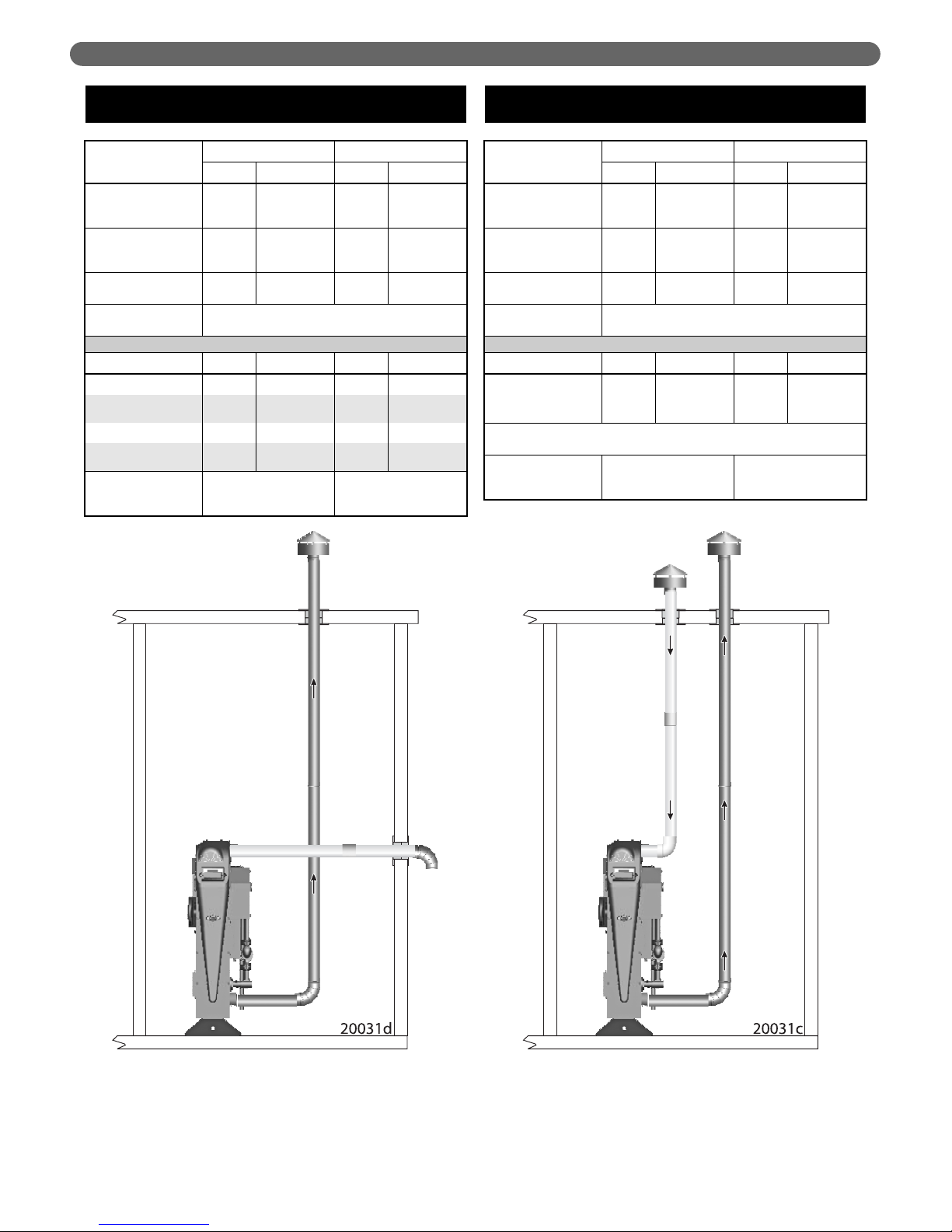
G. VENT PIPED THROUGH THE ROOF
(AIR PIPED THROUGH SIDE WALL)
H. VENT & AIR PIPED THROUGH THE ROOF
(SEPARATE VENT AND AIR TERMINATIONS)
Vent Components
92-2 92-4
Heat-Fab Z-Flex Heat-Fab Z-Flex
Vent Piping/Components
(Incl. Supports,
Thimbles, etc.)
EZ-Seal
3"
Z-Vent
3"
EZ-Seal
4"
Z-Vent
4"
Boiler Adapter (Adapts
from EZ-Seal to Z-Vent
Piping)
Not
Required
2SVSHTA03
Not
Required
2SVSHTA04
Rain Cap Vent
Termination
5300CI 2SVSRCF03 5400CI 2SVSRCF04
Joint Sealant,
as Needed
GE RTV106 or Equivalent
Air Components Heat-Fab Z-Flex Heat-Fab Z-Flex
Termination Elbow 9314TERM 2SVSTEX0390 9414TERM 2SVSTEX0490
Termination Pipe
Section (1 ft)
9302 2SVEPWCF0301 9402 2SVEPWCF0401
Termination Thimble 9393S 2SVSWTE03 9493S 2SVSWTE04
Gear Clamp
(Nose Clamp)
3" Clamp 7HS44XX 4" Clamp 7HS64XX
Air Piping/Components
(Incl. Supports,
Thimbles, etc.)
3" PVC, CPVC, ABS,
Galvanized or Aluminum
4" PVC, CPVC, ABS,
Galvanized or Aluminum
Vent Components
92-2 92-4
Heat-Fab Z-Flex Heat-Fab Z-Flex
Vent Piping/Components
(Incl. Supports,
Thimbles, etc.)
EZ-Seal
3"
Z-Vent
3"
EZ-Seal
4"
Z-Vent
4"
Boiler Adapter (Adapts
from EZ-Seal to Z-Vent
Piping)
Not
Required
2SVSHTA03
Not
Required
2SVSHTA04
Rain Cap Vent
Termination
5300CI 2SVSRCF03 5400CI 2SVSRCF04
Joint Sealant,
as Needed
GE RTV106 or Equivalent
Air Components Heat-Fab Z-Flex Heat-Fab Z-Flex
Rain Cap Termination 5300CI 2SVSRCF03 5400CI 2SVSRCF04
Termination Pipe
Section (3 ft)*
9307 2SVEPWCF0303 9407 2SVEPWCF0304
*Note: Standard air piping termination pipe section is 3 feet. A longer length can be
used if needed.
Air Piping/Components
(Incl. Supports,
Thimbles, etc.)
3" PVC, CPVC, ABS,
Galvanized or Aluminum
4" PVC, CPVC, ABS,
Galvanized or Aluminum
VENTING & AIR INLET PIPING
Page 16
12
I. VENT PIPED THROUGH A SIDE WALL
(COMBUSTION AIR FROM THE BOILER ROOM)
J. VENT & AIR PIPED THROUGH A SIDE WALL
(SEPARATE VENT AND AIR TERMINATIONS)
Vent Components
92-2 92-4
Heat-Fab Z-Flex Heat-Fab Z-Flex
Vent Piping/Components
(Incl. Supports,
Thimbles, etc.)
EZ-Seal
3"
Z-Vent
3"
EZ-Seal
4"
Z-Vent
4"
Boiler Adapter
(Adapts from EZ-Seal to
Z-Vent Piping)
Not
Required
2SVSHTA03
Not
Required
2SVSHTA04
Joint Sealant, as Needed GE RTV106 or Equivalent
Termination Elbow 9314TERM 2SVSTEX0390 9414TERM 2SVSTEX0490
Termination Pipe Section
(1 ft)
9302 2SVEPWCF0301 9402 2SVEPWCF0401
Termination Thimble 9393S 2SVSWTE03 9493S 2SVSWTE04
Gear Clamp (Nose
Clamp)
3" Clamp 7HS44XX 4" Clamp 7HS64XX
Vent Components
92-2 92-4
Heat-Fab Z-Flex Heat-Fab Z-Flex
Vent Piping/Components
(Incl. Supports,
Thimbles, etc.)
EZ-Seal
3"
Z-Vent
3"
EZ-Seal
4"
Z-Vent
4"
Boiler Adapter
(Adapts from EZ-Seal to
Z-Vent Piping)
Not
Required
2SVSHTA03
Not
Required
2SVSHTA04
Termination Elbow 9314TERM 2SVSTEX0390 9414TERM 2SVSTEX0490
Termination Pipe Section
(1 ft)
9302 2SVEPWCF0301 9402 2SVEPWCF0401
Termination Thimble 9393S 2SVSWTE03 9493S 2SVSWTE04
Gear Clamp (Nose
Clamp)
3" Clamp 7HS44XX 4" Clamp 7HS64XX
Joint Sealant, as Needed GE RTV106 or Equivalent
Air Components Heat-Fab Z-Flex Heat-Fab Z-Flex
Termination Elbow Same as Vent Termination Same as Vent Termination
Air Piping/Components
(Incl. Supports,
Thimbles, etc.)
3" PVC, CPVC, ABS,
Galvanized or Aluminum
4" PVC, CPVC, ABS,
Galvanized or Aluminum
VENTING & AIR INLET PIPING
Page 17
13
VENTING & AIR INLET PIPING
K. VENT & AIR PIPED THROUGH A SIDE WALL
(CONCENTRIC VENT/AIR TERMINATION)
Vent Components
92-2 92-4
Heat-Fab Heat-Fab
Vent Piping/Components
(Incl. Supports, Thimbles, etc.)
EZ-Seal, 3" Piping
Saf-T Vent SC Fittings for
Termination Assembly
EZ-Seal, 4" Piping
Saf-T Vent SC Fittings for
Termination Assembly
Termination Assembly:
• Single-wall Adapter
• Air Intake Tee
• 6" Straight Section
• 12" Straight Section
• Wall Plate (2 Required)
• Termination Adapter
• Mitered Termination
SC03ADEZ
SC03TAD3
SC0366
SC03L12
SC03FS
SC03HT
9390
SC04ADEZ
SC04TAD3
SC0466
SC04L12
SC04FS
SC04HT
9490
Joint Sealant, as Needed GE RTV106 or Equivalent
Air Components Heat-Fab Heat-Fab
Air Piping/Components
(Also Supports, Thimbles, etc.)
3" PVC, CPVC, ABS,
Galvanized or Aluminum
4" PVC, CPVC, ABS,
Galvanized or Aluminum
Page 18
14
A. BOILER VENT CONNECTION
1. The vent connection at the boiler is for Heat-Fab EZSeal vent piping only. To use Z-Flex Z-Vent venting
you must install the Z-Vent adapter, part number
2SVSHTA03 (92-2) or 2SVSHTA04 (92-4).
2. EZ-Seal Connection: Insert EZ-Seal pipe male end
into the boiler connection. Make sure the locking tabs
slide under the EZ-Seal locking ring. Bend back
locking tabs to complete the joint. Follow EZ-Seal
instructions to complete the vent piping installation.
3. Z-Vent adapter Installation: Insert male end of adapter
into boiler vent connection. Make sure the locking
tabs slide under the gear clamp on the adapter. Bend
back the locking tabs (as in left illustration above).
Then tighten the adapter gear clamp to finish the
connection. Follow Z-Vent instructions to connect ZVent piping.
The vent piping operates with positive pressure. The
vent piping must be completely sealed and securely
supported.
Use only the vent components listed in this manual.
Use of any other materials could result in vent
system failure.
Exposed vent pipe poses a potential burn hazard to
people and pets. Insulate or shield the pipe where
necessary to prevent risk.
Never drill through, or install screws into, the vent
pipe or vent components.
Failure to properly install the vent piping could result
in flue gas leakage, causing possible severe personal
injury, death or substantial property damage.
WARNING
Terminate the vent following the guidelines in this
manual. Avoid vent termination locations likely to be
affected by winds, snowdrifts, people and pets.
Protect building materials and vegetation from
degradation caused by the flue gases and
condensation.
WARNING
Code compliance – Follow all applicable local codes
when installing the vent system. Where codes differ
from this manual, follow code requirements. Contact
PB Heat if you have any questions regarding the
installation.
NOTICE
Figure 3A.1: Vertical Venting
EZ-Seal Vent Attachment Z-Vent Adapter
Attachment
3A. VENT & AIR PIPING: THROUGH THE
ROOF
(COMBUSTION AIR FROM THE BOILER ROOM)
VENT & AIR PIPING: THROUGH THE ROOF
Page 19
15
4. Slope horizontal runs toward the boiler. All horizontal
runs of vent pipe must slope continuously at least 1/4"
per foot (21 mm per meter) to ensure condensate
drains completely back to the boiler. DO NOT install
the vent piping with any sections that could trap
condensate.
B. VENT PIPING COMPONENTS
1. See Table 3A.1 for acceptable vent components. NO
OTHER vent materials are acceptable.
2. Carefully follow the instructions supplied by the vent
piping manufacturer.
3. The vent joints seal with elastomer rings in the pipe
and fittings. Avoid damaging these seals.
4. Cutting Z-Vent Pipe (Z-Vent only — DO NOT cut EZ-
Seal Pipe): Length adjustments with Z-Vent pipe can
be made by cutting the pipe, following the Z-Vent
instructions. Be sure to cut the pipe squarely and to
file the cut edge smooth after cutting. Rough pipe
ends will damage the seals. Support the pipe when
cutting to avoid making the pipe out of round.
5. Adjustable Lengths of EZ-Seal Pipe: Length
adjustments with EZ-Seal piping are made with slip-fit
adjustable length sections, not by cutting the pipe.
Make sure the adjustable length does not jut into
elbows or terminations. This could block flue gas and
condensate flow.
6. Maximum Vent Piping Length: See the table in Figure
3A.1 for the maximum allowable length. Each elbow
causes the same pressure drop as 10 feet of vent pipe,
so the allowable length reduces 10 feet for each elbow
used in the piping. When 45° elbows are used, two
45° elbows are equivalent to one 90° elbow.
7. Insulate the vent piping where it passes through
unheated areas to prevent condensate freeze-up.
8. If the pipe passes through an occupied space, install a
chase around the pipe, following the vent pipe
instructions and applicable codes.
9. Clearance from Combustible Materials: Provide
minimum clearance to all combustible materials of at
least 2 inches (51 mm).
10. Using an Existing Chimney as a Chase: The vent
piping can be routed through an existing UNUSED
and STRAIGHT chimney. DO NOT vent directly into
the chimney. Install the vent piping so it can be
inspected after installation. Follow vent pipe
manufacturer’s instructions for chimney-as-chase
installations.
C. SUPPORT THE VENT PIPING
COMPLETELY
1. DO NOT use the boiler vent connection to support
the vent piping. Provide support straps from the
ceiling or noncombustible saddle or pedestal supports
from the floor. This is required on ALL installations,
regardless of the length of the horizontal piping
connected to the boiler.
2. Vent piping cannot be supported from above (such as
relying on roof jack sections). You must install supports
on the horizontal piping before the vent turns upward.
3. Install at least one support on every horizontal run.
For horizontal runs longer than 5 feet (1.5 m), install a
support every 3 feet (0.9 m).
4. Follow the vent pipe manufacturer’s instructions for
placement and installation of supports.
D. FLOOR AND WALL PENETRATIONS
1. Follow applicable codes and the vent pipe instructions
to install fire stops, thimbles or other devices at all
floor and wall penetrations.
2. Provide minimum 2 inches (51 mm) clearance to all
combustible construction.
E. ROOF PENETRATIONS
Follow applicable codes and the vent pipe instructions to
install a roof jack, flashing and support. Long extensions
of vent pipe above the roof may require the use of guy
supports as specified in the vent pipe instructions.
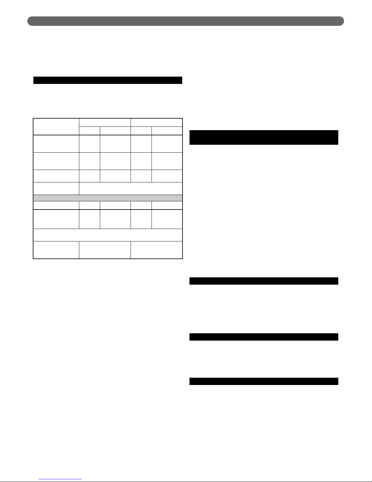
F. RAIN CAP TERMINATION
1. Use only the rain caps listed in Table 3A.1.
2. The rain cap exhaust opening must be at least 2 feet
(0.6 m) above the highest roof point within 10 feet, as
shown in Figure 3A.1. See the National Fuel Gas Code,
ANSI/NFPA 54 for details on pitched roof applications.
3. See Figure 3A.2 for additional minimum clearances.
VENT & AIR PIPING: THROUGH THE ROOF
Table 3A.1: Vent and Air System Components
Vent Components
92-2 92-4
Heat-Fab Z-Flex Heat-Fab Z-Flex
Vent Piping/Components
(Incl. Supports, Thimbles, etc.)
EZ-Seal3"Z-Vent3"EZ-Seal4"Z-Vent
4"
Boiler Adapter (Adapts from
EZ-Seal to Z-Vent Piping)
Not
Required
2SVSHTA03
Not
Required
2SVSHTA04
Rain Cap Vent Termination 5300CI 2SVSRCF03 5400CI 2SVSRCF04
Joint Sealant, as Needed GE RTV106 or Equivalent
Figure 3A.2: Vent Termination Minimum
Clearances
Page 20

16
G. COMBUSTION AIR OPENINGS
Combustion air must be supplied from the boiler room as
shown in Figure 1.1. Make sure the installation provides
air openings as required by applicable codes and this
manual.
H. MULTIPLE BOILER INSTALLATIONS
1. Each boiler must be individually vented. DO NOT use
combined venting.
2. Install multiple vents through the roof following all
guidelines for single-vent installations.
3. Install the vents so they are no closer than 12 inches
on centers.
VENT & AIR PIPING: THROUGH THE ROOF
Page 21
17
A. BOILER VENT CONNECTION
1. The vent connection at the boiler is for Heat-Fab EZSeal vent piping only. To use Z-Flex Z-Vent venting
you must install the Z-Vent adapter, part number
2SVSHTA03 (92-2) or 2SVSHTA04 (92-4).
2. EZ-Seal Connection: Insert EZ-Seal pipe male end
into the boiler connection. Make sure the locking tabs
slide under the EZ-Seal locking ring. Bend back
locking tabs to complete the joint. Follow EZ-Seal
instructions to complete the vent piping installation.
3. Z-Vent Adapter Installation: Insert male end of adapter
into boiler vent connection. Make sure the locking
tabs slide under the gear clamp on the adapter. Bend
back the locking tabs (as in left illustration above).
Then tighten the adapter gear clamp to finish the
connection. Follow Z-Vent instructions to connect ZVent piping.
VENT & AIR PIPING: THROUGH THE ROOF
The vent piping operates with positive pressure. The
vent piping must be completely sealed and securely
supported.
Use only the vent components listed in this manual.
Use of any other materials could result in vent
system failure.
Exposed vent pipe poses a potential burn hazard to
people and pets. Insulate or shield the pipe where
necessary to prevent risk.
Never drill through, or install screws into, the vent
pipe or vent components.
Failure to properly install the vent piping could result
in flue gas leakage, causing possible severe personal
injury, death or substantial property damage.
WARNING
Terminate the vent and air piping following the
guidelines in this manual. Avoid vent termination
locations likely to be affected by winds, snowdrifts,
people and pets. Protect building materials and
vegetation from degradation caused by the flue
gases and condensation.
WARNING
Code compliance – Follow all applicable local codes
when installing the vent system. Where codes differ
from this manual, follow code requirements. Contact
PB Heat if you have any questions regarding the
installation.
NOTICE
Figure 3B.1: Vertical Venting/Sidewall Air
EZ-Seal Vent Attachment Z-Vent Adapter
Attachment
3B. VENT & AIR PIPING: THROUGH THE
ROOF
(AIR PIPED THROUGH SIDE WALL)
Page 22
18
VENT & AIR PIPING: THROUGH THE ROOF
4. Slope horizontal runs toward the boiler. All horizontal
runs of vent pipe must slope continuously at least 1/4"
per foot (21 mm per meter) to ensure condensate
drains completely back to the boiler. DO NOT install
the vent piping with any sections that could trap
condensate.
B. VENT PIPING COMPONENTS
1. See Table 3B.1 for acceptable vent components. NO
OTHER vent materials are acceptable.
2. Carefully follow the instructions supplied by the vent
piping manufacturer.
3. The vent joints seal with elastomer rings in the pipe
and fittings. Avoid damaging these seals.
4. Cutting Z-Vent Pipe (Z-Vent only — DO NOT cut EZ-
Seal Pipe): Length adjustments with Z-Vent pipe can
be done by cutting the pipe, following the Z-Vent
instructions. Be sure to cut the pipe squarely and to
file the cut edge smooth after cutting. Rough pipe
ends will damage the seals. Support the pipe when
cutting to avoid making the pipe out of round.
5. Adjustable Lengths of EZ-Seal Pipe: Length
adjustments with EZ-Seal piping are done with slip-fit
adjustable length sections, not by cutting the pipe.
Make sure the adjustable length does not jut into
elbows or terminations. This could block flue gas and
condensate flow.
6. Maximum Vent Piping Length: See the table in Figure
3B.1 for the maximum allowable length. Each elbow
causes the same pressure drop as 10 feet of vent pipe,
so the allowable length reduces 10 feet for each elbow
used in the piping. When 45° elbows are used, two
45° elbows are equivalent to one 90° elbow.
7. Insulate the vent piping where it passes through
unheated areas to prevent condensate freeze-up.
8. If the pipe passes through an occupied space, install a
chase around the pipe, following the vent pipe
instructions and applicable codes.
9. Clearance from Combustible Materials: Provide
minimum clearance to all combustible materials of at
least 2 inches (51 mm).
10. Using an Existing Chimney as a Chase: The vent
piping can be routed through an existing STRAIGHT
chimney. DO NOT vent directly into the chimney.
Install the vent piping so it can be inspected after
installation. Follow vent pipe manufacturer’s
instructions for chimney-as-chase installations.
C. SUPPORT THE VENT PIPING
COMPLETELY
1. DO NOT use the boiler vent connection to support
the vent piping. Provide support straps from the
ceiling or noncombustible saddle or pedestal supports
from the floor. This is required on ALL installations,
regardless of the length of the horizontal piping
connected to the boiler.
2. Install at least one support on every horizontal run.
For horizontal runs longer than 5 feet (1.5 m), install a
support every 3 feet (0.9 m).
3. Vent piping cannot be supported from above (such as
relying on roof jack sections). You must install
supports on the horizontal piping before the vent turns
upward. Provide a support on the horizontal piping
within 6 inches of every upturned elbow to support
the vertical run.
4. Follow the vent pipe manufacturer’s instructions for
placement and installation of supports.
D. FLOOR AND WALL PENETRATIONS
1. Follow applicable codes and the vent pipe instructions
to install fire stops, thimbles or other devices at all
floor and wall penetrations.
2. Provide minimum 2 inches (51 mm) clearance to all
combustible construction.
E. ROOF PENETRATIONS
Follow applicable codes and the vent pipe instructions to
install a roof jack, flashing and support. Long extensions
of vent pipe above the roof may require the use of guy
supports as specified in the vent pipe instructions.
F. RAIN CAP TERMINATION
1. Use only the rain caps listed in Table 3B.1.
2. The rain cap exhaust opening must be at least 2 feet
(0.6 m) above the highest roof point within 10 feet, as
shown in Figure 3B.1. See the National Fuel Gas
Code, ANSI/NFPA 54 for details on pitched roof
applications.
3. See Figure 3B.2 for additional minimum clearances.
Table 3B.1: Vent and Air System Components
Vent Components
92-2 92-4
Heat-Fab Z-Flex Heat-Fab Z-Flex
Vent Piping/Components
(Incl. Supports,
Thimbles, etc.)
EZ-Seal
3"
Z-Vent
3"
EZ-Seal
4"
Z-Vent
4"
Boiler Adapter (Adapts
from EZ-Seal to Z-Vent
Piping)
Not
Required
2SVSHTA03
Not
Required
2SVSHTA04
Rain Cap Vent
Termination
5300CI 2SVSRCF03 5400CI 2SVSRCF04
Joint Sealant,
as Needed
GE RTV106 or Equivalent
Air Components Heat-Fab Z-Flex Heat-Fab Z-Flex
Termination Elbow 9314TERM 2SVSTEX0390 9414TERM 2SVSTEX0490
Termination Pipe
Section (1 ft)
9302 2SVEPWCF0301 9402 2SVEPWCF0401
Termination Thimble 9393S 2SVSWTE03 9493S 2SVSWTE04
Gear Clamp
(Nose Clamp)
3" Clamp 7HS44XX 4" Clamp 7HS64XX
Air Piping/Components
(Incl. Supports,
Thimbles, etc.)
3" PVC, CPVC, ABS,
Galvanized or Aluminum
4" PVC, CPVC, ABS,
Galvanized or Aluminum
Page 23
19
G. AIR PIPE CONNECTION
1. Before installing the air piping, install the air pipe
sidewall termination assembly (Item D, Figure 3B.1).
See instructions following.
2. Construct the air piping from PVC, CPVC or ABS
plastic, or galvanized or aluminum metallic pipe
(including flexible aluminum duct if desired).
3. Attach the air piping to the boiler air connection,
preferably using silicone RTV to seal the connection. If
the boiler room air is free of contaminants you can
use metallic duct tape to seal the joints. With age,
however, duct tape adhesives can loosen, so duct tape
is not as reliable as silicone RTV.
4. If the installation is required to meet direct vent
(sealed combustion) requirements, seal all joints withe
silicone RTV. The air pipe installation must be air-tight
and water-tight.
5. Maximum air piping length: See the table in Figure
3B.1, for the maximum allowable length. Each elbow
causes the same pressure drop as 10 feet of vent pipe,
so the allowable length reduces 10 feet for each elbow
used in the piping. When 45° elbows are used, two
45° elbows are equivalent to one 90° elbow.
H. SUPPORTING AIR PIPING
1. DO NOT use the boiler air connection to support the
air piping. Provide support straps from the ceiling or
install wall brackets.
2. Provide at least one support on all air pipe
installations.
3. Provide a support every 3 feet for air pipe lengths
greater than 5 feet horizontally.
4. Provide a support on the horizontal piping within 6
inches of every upturned elbow to support the vertical
run.
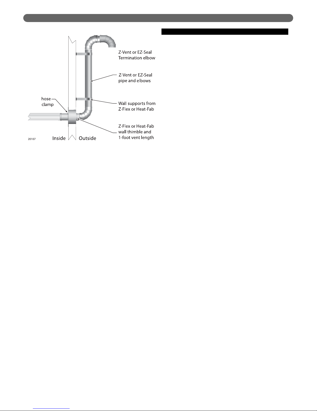
I. AIR PIPE TERMINATION
1. See Table 3B.1 for part numbers of the sidewall
termination components required for Z-Vent and EZSeal air pipe installations. The air piping termination
must be constructed using the stainless steel vent
materials listed in Table 3B.1 to ensure the
configuration is correct. DO NOT terminate the air
piping with any other method.
2. Termination Assembly Components:
a. Wall Thimble
: Use only the thimble listed in Table
3B.1. The hole in the thimble will prevent the pipe
length (B) from being pushed inward. The raised
portion of the pipe female end is too large to pass
through the hole in the thimble. Follow the vent
pipe manufacturer’s instructions supplied with the
thimble. If the wall thimble isn’t long enough for
the application, follow the vent manufacturer’s
instructions to add an extension.
Alternate Construction
: The air pipe can be
inserted through a hole without using a thimble.
For this option, attach a storm collar on both the
inside and outside walls at the penetration. Before
attaching the collars, seal around the air pipe
thoroughly with silicone RTV to prevent air
leakage or insect access. The storm collar tightens
around the vent pipe with a gear clamp. This
prevents movement of the finished assembly. You
will still need to use the length of vent pipe and
the termination elbow described below.
b. Length of Vent Pipe
: Use a 1-foot length of vent
pipe as listed in Table 3B.1 unless the wall
penetration requires a longer length. If a longer
length is required, use a length of EZ-Seal or ZVent long enough for the application.
Insert the pipe from OUTSIDE, male end first. The
pipe will stop at the raised section of the female end.
VENT & AIR PIPING: THROUGH THE ROOF
COMBUSTION AIR MUST BE UNCONTAMINATED
Construction dust: If the boiler is operated while the
building is under construction it must be protected
from wood, concrete, sheet rock and other types of
dust. Failure to properly protect the boiler from
construction dust will damage the boiler.
Combustion air contaminated with fluorocarbons or
other halogenated compounds, such as laundry
products, cleaning solvents and refrigerants will
result in the formation of acids in the combustion
chamber and vent piping. These acids will cause
premature failure of the boiler and vent, causing
possible severe personal injury, death or substantial
property damage.
If the boiler room, or any room through which the air
piping travels, may contain contaminants as listed
above, you MUST seal air pipe joints with silicone
RTV to prevent contaminants from entering the
boiler combustion air. The finished air piping
installation must be air-tight and water-tight.
WARNING
Figure 3B.2: Termination Minimum Clearances
When using metallic piping, seal all of the longitudinal
seam joints in addition to the component joints.
NOTICE
Page 24
20
VENT & AIR PIPING: THROUGH THE ROOF
c. Gear Clamp: Use a hose clamp or a gear clamp
manufactured by the vent manufacturer (see Table
3B.2).
Slide the clamp over the male end of the pipe
after the pipe has been inserted from outside.
From the inside, pull the pipe so it is firmly against
the outside plate.
Push the gear clamp against the inside plate and
tighten securely. This will prevent the termination
assembly from being pushed outward.
d. Termination Elbow
: Use only the termination
elbow listed in Table 3B.2. The elbow must be
pointed downward.
Before inserting the male end of the elbow into
the pipe, apply a bead of silicone RTV and spread
around the end.
Insert the termination elbow and secure using the
vent pipe manufacturer’s joint assembly
procedure.
Termination Location
: Install the air pipe
termination where it meets the minimum
clearances shown in Figure 3B.4.
Appliance exhaust outlets: Install the air intake at
least 2 feet below and 5 feet horizontally from any
appliance vent outlet.
Exiting below grade or minimum height: See
Figure 3B.5. When the air pipe must exit the
building below grade or below the minimum
height for the termination elbow, install vertical
piping as necessary for the termination elbow to
be high enough to meet the minimum clearances
of Figure 3B.4. Make sure to support the piping
using wall brackets available from the vent pipe
manufacturer.
Figure 3B.1: Vertical Venting/Sidewall Air
(Partially Repeated from Page 17)
Figure 3B.4: Minimum Clearances to Air
Termination
Figure 3B.2: Sidewall Air Pipe Termination
Assembly
Page 25
21
J. MULTIPLE BOILER INSTALLATIONS
1. Venting Multiple Boilers:
a. Each boiler must be individually vented. DO NOT
use combined venting.
b. Install multiple vents through the roof following all
guidelines for single-vent installations.
c. Install the vents so they are no closer than 12
inches on centers.
2. Air Piping for Multiple Boilers:
a. Air for each boiler must be individually piped. DO
NOT use combined air piping.
b. Install multiple air pipes through the side wall
following all guidelines for single-air pipe
installations.
c. Install the terminations so they are no closer than
12 inches on centers.
VENT & AIR PIPING: THROUGH THE ROOF
Figure 3B.2: Using External Piping to Raise the
Termination
Page 26

22
A. BOILER VENT CONNECTION
1. The vent connection at the boiler is for Heat-Fab EZSeal vent piping only. To use Z-Flex Z-Vent venting
you must install the Z-Vent adapter, part number
2SVSHTA03 (92-2) or 2SVSHTA04 (92-4).
2. EZ-Seal Connection: Insert EZ-Seal pipe male end
into the boiler connection. Make sure the locking tabs
slide under the EZ-Seal locking ring. Bend back
locking tabs to complete the joint. Follow EZ-Seal
instructions to complete the vent piping installation.
3. Z-Vent Adapter Installation: Insert male end of adapter
into boiler vent connection. Make sure the locking
tabs slide under the gear clamp on the adapter. Bend
back the locking tabs (as in left illustration above).
Then tighten the adapter gear clamp to finish the
connection. Follow Z-Vent instructions to connect
Z-Vent piping.
The vent piping operates with positive pressure. The
vent piping must be completely sealed and securely
supported.
Use only the vent components listed in this manual.
Use of any other materials could result in vent
system failure.
Exposed vent pipe poses a potential burn hazard to
people and pets. Insulate or shield the pipe where
necessary to prevent risk.
Never drill through, or install screws into, the vent
pipe or vent components.
Failure to properly install the vent piping could result
in flue gas leakage, causing possible severe personal
injury, death or substantial property damage.
WARNING
Terminate the vent and air piping following the
guidelines in this manual. Avoid vent termination
locations likely to be affected by winds, snowdrifts,
people and pets. Protect building materials and
vegetation from degradation caused by the flue
gases and condensation.
WARNING
Code compliance – Follow all applicable local codes
when installing the vent system. Where codes differ
from this manual, follow code requirements. Contact
PB Heat if you have any questions regarding the
installation.
NOTICE
Figure 3C.1: Vertical Venting
VENT & AIR PIPING: THROUGH THE ROOF
3C. VENT PIPING: THROUGH THE ROOF
(SEPARATE TERMINATIONS)
EZ-Seal Vent Attachment Z-Vent Adapter
Attachment
Page 27
23
4. Slope horizontal runs toward the boiler. All horizontal
runs of vent pipe must slope continuously at least 1/4"
per foot (21 mm per meter) to ensure condensate
drains completely back to the boiler. DO NOT install
the vent piping with any sections that could trap
condensate.
B. VENT PIPING COMPONENTS
1. See Table 3C.1 for acceptable vent components. NO
OTHER vent materials are acceptable.
2. Carefully follow the instructions supplied by the vent
piping manufacturer.
3. The vent joints seal with elastomer rings in the pipe
and fittings. Avoid damaging these seals.
4. Cutting Z-Vent Pipe (Z-Vent only — DO NOT cut EZ-
Seal Pipe): Length adjustments with Z-Vent pipe can
be done by cutting the pipe, following the Z-Vent
instructions. Be sure to cut the pipe squarely and to
file the cut edge smooth after cutting. Rough pipe
ends will damage the seals. Support the pipe when
cutting to avoid making the pipe out of round.
5. Adjustable Lengths of EZ-Seal Pipe: Length
adjustments with EZ-Seal piping are done with slip-fit
adjustable length sections, not by cutting the pipe.
Make sure the adjustable length does not jut into
elbows or terminations. This could block flue gas and
condensate flow.
6. Maximum Vent Piping Length: See the table in Figure
3C.1 for the maximum allowable length. Each elbow
causes the same pressure drop as 10 feet of vent pipe,
so the allowable length reduces 10 feet for each elbow
used in the piping. When 45° elbows are used, two
45° elbows are equivalent to one 90° elbow.
7. Insulate the vent piping where it passes through
unheated areas to prevent condensate freeze-up.
8. If the pipe passes through an occupied space, install a
chase around the pipe, following the vent pipe
instructions and applicable codes.
9. Clearance from combustible materials: Provide
minimum clearance to all combustible materials of at
least 2 inches (51 mm).
10. Using an existing chimney as a chase: The vent piping
and air piping can be routed through an existing
UNUSED and STRAIGHT chimney. DO NOT vent
directly into the chimney. Install the vent piping so it
can be inspected after installation. Follow vent pipe
manufacturer’s instructions for chimney-as-chase
installations.
C. SUPPORT THE VENT PIPING
COMPLETELY
1. DO NOT use the boiler vent connection to support
the vent piping. Provide support straps from the
ceiling or noncombustible saddle or pedestal supports
from the floor. This is required on ALL installations,
regardless of the length of the horizontal piping
connected to the boiler.
2. Install at least one support on every horizontal run.
For horizontal runs longer than 5 feet (1.5 m), install a
support every 3 feet (0.9 m).
3. Vent piping cannot be supported from above (such as
relying on roof jack sections). You must install
supports on the horizontal piping before the vent turns
upward. Provide a support on the horizontal piping
within 6 inches of every upturned elbow to support
the vertical run.
4. Follow the vent pipe manufacturer’s instructions for
placement and installation of supports.
D. FLOOR AND WALL PENETRATIONS
1. Follow applicable codes and the vent pipe instructions
to install fire stops, thimbles or other devices at all
floor and wall penetrations.
2. Provide minimum 2 inches (51 mm) clearance to all
combustible construction.
E. ROOF PENETRATIONS
Follow applicable codes and the vent pipe instructions to
install a roof jack, flashing and support. Long extensions
of vent pipe above the roof may require the use of guy
supports as specified in the vent pipe instructions.
F. RAIN CAP TERMINATION
1. Use only the rain caps listed in Table 3C.1.
2. The rain cap exhaust opening must be at least 2 feet
(0.6 m) above the highest roof point within 10 feet, as
shown in Figure 3C.1. See the National Fuel Gas
Code, ANSI/NFPA 54 for details on pitched roof
applications.
Table 3C.1: Vent System Components
VENT & AIR PIPING: THROUGH THE ROOF
Vent Components
92-2 92-4
Heat-Fab Z-Flex Heat-Fab Z-Flex
Vent Piping/Components
(Incl. Supports,
Thimbles, etc.)
EZ-Seal
3"
Z-Vent
3"
EZ-Seal
4"
Z-Vent
4"
Boiler Adapter (Adapts
from EZ-Seal to Z-Vent
Piping)
Not
Required
2SVSHTA03
Not
Required
2SVSHTA04
Rain Cap Vent
Termination
5300CI 2SVSRCF03 5400CI 2SVSRCF04
Joint Sealant,
as Needed
GE RTV106 or Equivalent
Air Components Heat-Fab Z-Flex Heat-Fab Z-Flex
Rain Cap Termination 5300CI 2SVSRCF03 5400CI 2SVSRCF04
Termination Pipe
Section (3 ft)*
9307 2SVEPWCF0303 9407 2SVEPWCF0304
*Note: Standard air piping termination pipe section is 3 feet. A longer length can be
used if needed.
Air Piping/Components
(Incl. Supports,
Thimbles, etc.)
3" PVC, CPVC, ABS,
Galvanized or Aluminum
4" PVC, CPVC, ABS,
Galvanized or Aluminum
Page 28
24
3. See Figure 3C.2 for additional minimum clearances.
The vent must always terminate at least 4 feet (1.2 m)
above the air intake termination.
G. AIR PIPE CONNECTION
1. Construct the air piping from PVC, CPVC or ABS
plastic, or galvanized or aluminum metallic pipe
(including flexible aluminum duct if desired).
2. Attach the air piping to the boiler air connection,
preferably using silicone RTV to seal the connection. If
the boiler room air is free of contaminants you can
use metallic duct tape to seal the joints. With age,
however, duct tape adhesives can loosen, so duct tape
is not as reliable as silicone RTV.
3. If the installation is required to meet direct vent
(sealed combustion) requirements, seal all joints with
silicone RTV. The air pipe installation must be air-tight
and water-tight.
4. The air piping connects to the stainless steel pipe
section attached to the air intake rain cap termination
(Item F, Figure 3C.1). See instructions following.
5. Maximum air piping length: See the table in Figure
3C.1 for the maximum allowable length. Each elbow
causes the same pressure drop as 10 feet of vent pipe,
so the allowable length reduces 10 feet for each elbow
used in the piping. When 45° elbows are used, two
45° elbows are equivalent to one 90° elbow.
H. SUPPORTING AIR PIPING
1. DO NOT use the boiler air connection to support the
air piping. Provide support straps from the ceiling or
install wall brackets.
2. Provide at least one support on all air pipe
installations.
3. Provide a support every 3 feet for air pipe lengths
greater than 5 feet horizontally.
4. Provide a support on the horizontal piping within 6
inches of every upturned elbow to support the vertical
run.
I. AIR PIPE TERMINATION
1. See Table 3C.1 for part numbers of the vertical
termination components required for Z-Vent and EZSeal air pipe installations. The air piping termination
must be constructed using the stainless steel vent
materials listed in Table 3C.1 to ensure the
configuration is correct. DO NOT terminate the air
piping with any other method.
2. Termination Assembly Components:
a. Rain Cap
: Use only the rain cap listed in Table
3C.1, the same cap as used on the vent
termination.
Install the rain cap so it meets the minimum
clearances shown in Figure 3C.2.
b. Length of Vent Pipe
: Use a 3-foot length of vent
pipe as listed in Table 3C.1 unless the roof
penetration requires a longer length to meet
minimum clearances. If a longer length is required,
use a length of EZ-Seal or Z-Vent long enough for
the application.
Attach the air piping to the male end (bottom end)
of the stainless steel pipe.
c. Roof penetration components: Use the same
components as used for the vent penetration.
VENT & AIR PIPING: THROUGH THE ROOF
COMBUSTION AIR MUST BE UNCONTAMINATED
Construction dust: If the boiler is operated while the
building is under construction it must be protected
from wood, concrete, sheet rock and other types of
dust. Failure to properly protect the boiler from
construction dust will damage the boiler.
Combustion air contaminated with fluorocarbons or
other halogenated compounds, such as laundry
products, cleaning solvents and refrigerants will
result in the formation of acids in the combustion
chamber and vent piping. These acids will cause
premature failure of the boiler and vent, causing
possible severe personal injury, death or substantial
property damage.
If the boiler room, or any room through which the air
piping travels, may contain contaminants as listed
above, you MUST seal air pipe joints with silicone
RTV to prevent contaminants from entering the
boiler combustion air. The finished air piping
installation must be air-tight and water-tight.
WARNING
When using metallic piping, seal all of the longitudinal
seam joints in addition to the component joints.
NOTICE
Figure 3C.2: Termination Minimum Clearances
Page 29

25
J. MULTIPLE BOILER INSTALLATIONS
1. Venting Multiple Boilers:
a. Each boiler must be individually vented. DO NOT
use combined venting.
b. Install multiple vents through the roof following all
guidelines for single-vent installations.
c. Install the vents so they are no closer than 12
inches on centers.
d. Provide minimum 5 feet between the center line
of any vent termination and any air intake
termination.
2. Air Piping for Multiple Boilers:
a. Air for each boiler must be individually piped. DO
NOT use combined air piping.
b. Install multiple air pipes through the side wall
following all guidelines for single-air pipe
installations.
c. Install the terminations so they are no closer than
12 inches on centers.
d. Provide minimum 5 feet between the center line
of any vent termination and any air intake
termination.
VENT & AIR PIPING: THROUGH THE ROOF
Page 30
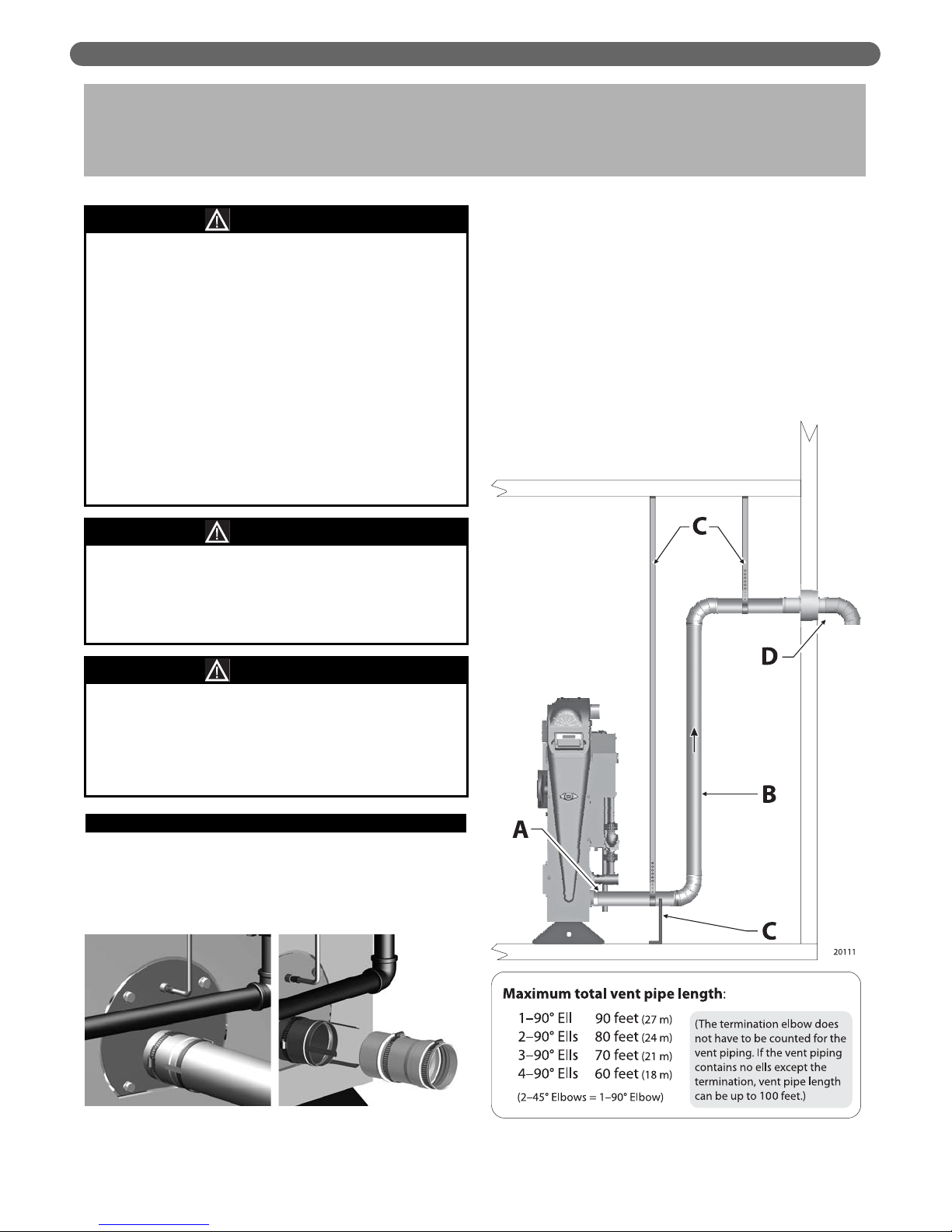
26
A. BOILER VENT CONNECTION
1. The vent connection at the boiler is for Heat-Fab EZSeal vent piping only. To use Z-Flex Z-Vent venting
you must install the Z-Vent adapter, part number
2SVSHTA03 (92-2) or 2SVSHTA04 (92-4).
2. EZ-Seal Connection: Insert EZ-Seal pipe male end
into the boiler connection. Make sure the locking tabs
slide under the EZ-Seal locking ring. Bend back
locking tabs to complete the joint. Follow EZ-Seal
instructions to complete the vent piping installation.
3. Z-Vent Adapter Installation: Insert male end of adapter
into boiler vent connection. Make sure the locking
tabs slide under the gear clamp on the adapter. Bend
back the locking tabs (as in left illustration above).
Then tighten the adapter gear clamp to finish the
connection. Follow Z-Vent instructions to connect ZVent piping.
The vent piping operates with positive pressure. The
vent piping must be completely sealed and securely
supported.
Use only the vent components listed in this manual.
Use of any other materials could result in vent
system failure.
Exposed vent pipe poses a potential burn hazard to
people and pets. Insulate or shield the pipe where
necessary to prevent risk.
Never drill through, or install screws into, the vent
pipe or vent components.
Failure to properly install the vent piping could result
in flue gas leakage, causing possible severe personal
injury, death or substantial property damage.
WARNING
Terminate the vent and air piping following the
guidelines in this manual. Avoid vent termination
locations likely to be affected by winds, snowdrifts,
people and pets. Protect building materials and
vegetation from degradation caused by the flue
gases and condensation.
WARNING
Code compliance – Follow all applicable local codes
when installing the vent system. Where codes differ
from this manual, follow code requirements. Contact
PB Heat if you have any questions regarding the
installation.
NOTICE
Figure 3D.1: Vertical Venting/Sidewall Air
VENT & AIR PIPING: THROUGH A SIDE WALL
3D. VENT & AIR PIPING: THROUGH A SIDE
WALL
(COMBUSTION AIR FROM THE BOILER ROOM)
EZ-Seal Vent Attachment Z-Vent Adapter
Attachment
Page 31

27
4. Slope horizontal runs toward the boiler. All horizontal
runs of vent pipe must slope continuously at least 1/4"
per foot (21 mm per meter) to ensure condensate
drains completely back to the boiler. DO NOT install
the vent piping with any sections that could trap
condensate.
B. VENT PIPING COMPONENTS
1. See Table 3D.1 for acceptable vent components. NO
OTHER vent materials are acceptable.
2. Carefully follow the instructions supplied by the vent
piping manufacturer.
3. The vent joints seal with elastomer rings in the pipe
and fittings. Avoid damaging these seals.
4. Cutting Z-Vent Pipe (Z-Vent only — DO NOT cut EZ-
Seal Pipe): Length adjustments with Z-Vent pipe can
be done by cutting the pipe, following the Z-Vent
instructions. Be sure to cut the pipe squarely and to
file the cut edge smooth after cutting. Rough pipe
ends will damage the seals. Support the pipe when
cutting to avoid making the pipe out of round.
5. Adjustable Lengths of EZ-Seal Pipe: Length
adjustments with EZ-Seal piping are done with slip-fit
adjustable length sections, not by cutting the pipe.
Make sure the adjustable length does not jut into
elbows or terminations. This could block flue gas and
condensate flow.
6. Maximum Vent Piping Length: See the table in Figure
3D.1 for the maximum allowable length. Each elbow
causes the same pressure drop as 10 feet of vent pipe,
so the allowable length reduces 10 feet for each elbow
used in the piping. When 45° elbows are used, two
45° elbows are equivalent to one 90° elbow.
7. Insulate the vent piping where it passes through
unheated areas to prevent condensate freeze-up. Do
not insulate the within 18 inches of the termination
when it passes through a combustible wall.
8. If the pipe passes through an occupied space, install a
chase around the pipe, following the vent pipe
instructions and applicable codes.
9. Clearance from Combustible Materials: Provide
minimum clearance to all combustible materials of at
least 2 inches (51 mm).
C. SUPPORT THE VENT PIPING
COMPLETELY
1. DO NOT use the boiler vent connection to support
the vent piping. Provide support straps from the
ceiling or noncombustible saddle or pedestal supports
from the floor. This is required on ALL installations,
regardless of the length of the horizontal piping
connected to the boiler.
2. Install at least one support on every horizontal run.
For horizontal runs longer than 5 feet (1.5 m), install a
support every 3 feet (0.9 m).
3. Vent piping cannot be supported from above (such as
relying on roof jack sections). You must install
supports on the horizontal piping before the vent turns
upward. Provide a support on the horizontal piping
within 6 inches of every upturned elbow to support
the vertical run.
4. Follow the vent pipe manufacturer’s instructions for
placement and installation of supports.
5. Follow applicable codes and the vent pipe instructions
to install fire stops, thimbles or other devices at all
floor and wall penetrations.
6. Provide minimum 2 inches (51 mm) clearance to all
combustible construction.
D. SIDEWALL TERMINATION
1. See Table 3D.1 for part numbers of the sidewall
termination components required for Z-Vent and EZSeal vent pipe installations. The vent termination must
be constructed using the stainless steel vent materials
listed in Table 3D.1 to ensure the configuration is
correct. DO NOT terminate the air piping with any
other method.
a. Wall Thimble
: Use only the thimble listed in Table
3D.1. The hole in the thimble will prevent the pipe
length (B) from being pushed inward. The raised
portion of the pipe female end is too large to pass
through the hole in the thimble. Follow the vent
pipe manufacturer’s instructions supplied with the
thimble. If the wall thimble isn’t long enough for
the application, follow the vent manufacturer’s
instructions to add an extension.
Noncombustible Walls
: For noncombustible walls
ONLY, you can omit the thimble. For this option,
attach a storm collar on both the inside and
outside walls at the penetration. Before attaching
the collars, seal around the vent pipe thoroughly
with silicone RTV to prevent air leakage or insect
access. The storm collar tightens around the vent
pipe with a gear clamp. This prevents movement
of the finished assembly. You will still need to use
the length of vent pipe and the termination elbow
described below.
VENT & AIR PIPING: THROUGH A SIDE WALL
Table 3D.1: Vent and Air System Components
Vent Components
92-2 92-4
Heat-Fab Z-Flex Heat-Fab Z-Flex
Vent Piping/Components
(Incl. Supports,
Thimbles, etc.)
EZ-Seal
3"
Z-Vent
3"
EZ-Seal
4"
Z-Vent
4"
Boiler Adapter
(Adapts from EZ-Seal to
Z-Vent Piping)
Not
Required
2SVSHTA03
Not
Required
2SVSHTA04
Joint Sealant, as Needed GE RTV106 or Equivalent
Termination Elbow 9314TERM 2SVSTEX0390 9414TERM 2SVSTEX0490
Termination Pipe Section
(1 ft)
9302 2SVEPWCF0301 9402 2SVEPWCF0401
Termination Thimble 9393S 2SVSWTE03 9493S 2SVSWTE04
Gear Clamp (Nose
Clamp)
3" Clamp 7HS44XX 4" Clamp 7HS64XX
Page 32

28
b. Length of Vent Pipe: Use a 1-foot length of vent
pipe as listed in Table 3D.1 unless the wall
penetration quires a longer length. If a longer
length is required, use a length of EZ-Seal or ZVent long enough for the application.
Insert the pipe from OUTSIDE, male end first. The
pipe will stop at the raised section of the female
end.
c. Gear Clamp
: Use a hose clamp or a gear clamp
manufactured by the vent manufacturer (see Table
3D.1).
Slide the clamp over the male end of the pipe
after the pipe has been inserted from outside.
From the inside, pull the pipe so it is firmly against
the outside plate.
Push the gear clamp against the inside plate and
tighten securely. This will prevent the termination
assembly from being pushed outward.
d. Termination Elbow
: Use only the termination
elbow listed in Table 3D.1. The elbow must be
pointed downward.
Before inserting the male end of the elbow into
the pipe, apply a bead of silicone RTV and spread
around the end.
Insert the termination elbow and secure using the
vent pipe manufacturer’s joint assembly
procedure.
Termination Location
: Install the vent pipe
termination where it meets the minimum
clearances shown in Figure 3D.3.
Exiting below grade or snow line: See Figure
3D.4. When the vent pipe must exit the building
grade or below the minimum height for the
termination elbow, install vertical piping as
necessary for the termination elbow to be high
enough to meet the minimum clearances of Figure
3D.3. Make sure to support the piping using wall
brackets available from the vent pipe
manufacturer.
If the pipe extends more than 3 feet, insulate the
external portion of the pipe and fittings with at
least 1/2" closed-cell foam polyolefin pipe
insulation.
Figure 3D.3: Termination Minimum Clearances
VENT & AIR PIPING: THROUGH A SIDE WALL
Figure 3D.2: Termination Minimum Clearances
Page 33

29
E. COMBUSTION AIR OPENINGS
Combustion air must be supplied from the boiler room as
shown in Figure 1.1. Make sure the installation provides
air openings as required by applicable codes and the
Boiler manual.
F. MULTIPLE BOILER INSTALLATIONS
1. Each boiler must be individually vented. DO NOT use
combined venting.
2. Install multiple vents through the side wall following
all guidelines for single-vent installations.
3. Install the vents so they are no closer than 12 inches
(305 mm) on centers.
Figure 3D.4: Using External Piping to Raise the
Termination
To convert to metric dimensions:
meters=feet x 0.3
millimeters=inches x 25.4
VENT & AIR PIPING: THROUGH A SIDE WALL
Page 34

30
A. BOILER VENT CONNECTION
1. The vent connection at the boiler is for Heat-Fab EZSeal vent piping only. To use Z-Flex Z-Vent venting
you must install the Z-Vent adapter, part number
2SVSHTA03 (92-2) or 2SVSHTA04 (92-4).
2. EZ-Seal Connection: Insert EZ-Seal pipe male end
into the boiler connection. Make sure the locking tabs
slide under the EZ-Seal locking ring. Bend back
locking tabs to complete the joint. Follow EZ-Seal
instructions to complete the vent piping installation.
3. Z-Vent Adapter Installation: Insert male end of adapter
into boiler vent connection. Make sure the locking
tabs slide under the gear clamp on the adapter. Bend
back the locking tabs (as in left illustration above).
Then tighten the adapter gear clamp to finish the
connection. Follow Z-Vent instructions to connect
Z-Vent piping.
VENT & AIR PIPING: THROUGH A SIDE WALL
The vent piping operates with positive pressure. The
vent piping must be completely sealed and securely
supported.
Use only the vent components listed in this manual.
Use of any other materials could result in vent
system failure.
Exposed vent pipe poses a potential burn hazard to
people and pets. Insulate or shield the pipe where
necessary to prevent risk.
Never drill through, or install screws into, the vent
pipe or vent components.
Failure to properly install the vent piping could result
in flue gas leakage, causing possible severe personal
injury, death or substantial property damage.
WARNING
Terminate the vent and air piping following the
guidelines in this manual. Avoid vent termination
locations likely to be affected by winds, snowdrifts,
people and pets. Protect building materials and
vegetation from degradation caused by the flue gases
and condensation.
WARNING
Code compliance – Follow all applicable local codes
when installing the vent system. Where codes differ
from this manual, follow code requirements. Contact
PB Heat if you have any questions regarding the
installation.
NOTICE
Figure 3E.1: Vertical Venting/Sidewall Air
3E. VENT & AIR PIPING: THROUGH A SIDE
WALL
(SEPARATE TERMINATIONS)
EZ-Seal Vent Attachment Z-Vent Adapter
Attachment
Page 35

31
4. Slope horizontal runs toward the boiler. All horizontal
runs of vent pipe must slope continuously at least 1/4"
per foot (21 mm per meter) to ensure condensate
drains completely back to the boiler. DO NOT install
the vent piping with any sections that could trap
condensate.
B. VENT PIPING COMPONENTS
1. See Table 3E.1 for acceptable vent components. NO
OTHER vent materials are acceptable.
2. Carefully follow the instructions supplied by the vent
piping manufacturer.
3. Install the sidewall vent termination before installing
the vent piping.
4. The vent joints seal with elastomer rings in the pipe
and fittings. Avoid damaging these seals.
5. Cutting Z-Vent Pipe (Z-Vent only — DO NOT cut EZ-
Seal Pipe): Length adjustments with Z-Vent pipe can
be done by cutting the pipe, following the Z-Vent
instructions. Be sure to cut the pipe squarely and to
file the cut edge smooth after cutting. Rough pipe
ends will damage the seals. Support the pipe when
cutting to avoid making the pipe out of round.
6. Adjustable Lengths of EZ-Seal Pipe: Length
adjustments with EZ-Seal piping are done with slip-fit
adjustable length sections, not by cutting the pipe.
Make sure the adjustable length does not jut into
elbows or terminations. This could block flue gas and
condensate flow.
7. Maximum Vent Piping Length: See the table in Figure
3E.1 for the maximum allowable length. Each elbow
causes the same pressure drop as 10 feet of vent pipe,
so the allowable length reduces 10 feet for each elbow
used in the piping. When 45° elbows are used, two
45° elbows are equivalent to one 90° elbow.
8. Insulate the vent piping where it passes through
unheated areas to prevent condensate freeze-up. If the
vent terminates through a combustible wall, leave the
last 18 inches of vent pipe uninsulated.
9. If the pipe passes through an occupied space, install a
chase around the pipe, following the vent pipe
instructions and applicable codes.
10. Clearance from Combustible Materials: Provide
minimum clearance to all combustible materials of at
least 2 inches (51 mm).
C. SUPPORT THE VENT PIPING
COMPLETELY
1. DO NOT use the boiler vent connection to support
the vent piping. Provide support straps from the
ceiling or noncombustible saddle or pedestal supports
from the floor. This is required on ALL installations,
regardless of the length of the horizontal piping
connected to the boiler.
2. Install at least one support on every horizontal run.
For horizontal runs longer than 5 feet (1.5 m), install a
support every 3 feet (0.9 m).
3. Vent piping cannot be supported from above (such as
relying on roof jack sections). You must install
supports on the horizontal piping before the vent turns
upward. Provide a support on the horizontal piping
within 6 inches of every upturned elbow to support
the vertical run.
4. Follow the vent pipe manufacturer’s instructions for
placement and installation of supports.
5. Follow applicable codes and the vent pipe instructions
to install fire stops, thimbles or other devices at all
floor and wall penetrations.
6. Provide minimum 2 inches (51 mm) clearance to all
combustible construction.
D. AIR PIPE CONNECTION
1. Before installing the air piping, install the air pipe
sidewall termination assembly (Item F, Figure 3E.1).
See instructions on next page.
2. Construct the air piping from PVC, CPVC or ABS
plastic, or galvanized or aluminum metallic pipe
(including flexible aluminum duct if desired).
3. Attach the air piping to the boiler air connection,
preferably using silicone RTV to seal the connection. If
the boiler room air is free of contaminants you can
use metallic duct tape to seal the joints. With age,
however, duct tape adhesives can loosen, so duct tape
is not as reliable as silicone RTV.
VENT & AIR PIPING: THROUGH A SIDE WALL
Table 3E.1: Vent and Air System Components
When using metallic piping, seal all of the longitudinal
seam joints in addition to the component joints.
NOTICE
Vent Components
92-2 92-4
Heat-Fab Z-Flex Heat-Fab Z-Flex
Vent Piping/Components
(Incl. Supports,
Thimbles, etc.)
EZ-Seal
3"
Z-Vent
3"
EZ-Seal
4"
Z-Vent
4"
Boiler Adapter
(Adapts from EZ-Seal to
Z-Vent Piping)
Not
Required
2SVSHTA03
Not
Required
2SVSHTA04
Termination Elbow 9314TERM 2SVSTEX0390 9414TERM 2SVSTEX0490
Termination Pipe Section
(1 ft)
9302 2SVEPWCF0301 9402 2SVEPWCF0401
Termination Thimble 9393S 2SVSWTE03 9493S 2SVSWTE04
Gear Clamp (Nose
Clamp)
3" Clamp 7HS44XX 4" Clamp 7HS64XX
Joint Sealant, as Needed GE RTV106 or Equivalent
Air Components Heat-Fab Z-Flex Heat-Fab Z-Flex
Termination Elbow Same as Vent Termination Same as Vent Termination
Air Piping/Components
(Incl. Supports,
Thimbles, etc.)
3" PVC, CPVC, ABS,
Galvanized or Aluminum
4" PVC, CPVC, ABS,
Galvanized or Aluminum
Page 36

32
4. If the installation is required to meet direct vent
(sealed combustion) requirements, seal all joints withe
silicone RTV. The air pipe installation must be air-tight
and water-tight.
5. Maximum Air Piping Length
: See the table in Figure
3E.1 for the maximum allowable length. Each elbow
causes the same pressure drop as 10 feet of vent pipe,
so the allowable length reduces 10 feet for each elbow
used in the piping. When 45° elbows are used, two
45° elbows are equivalent to one 90° elbow.
E. SUPPORTING AIR PIPING
1. DO NOT use the boiler air connection to support the
air piping. Provide support straps from the ceiling or
install wall brackets.
2. Provide at least one support on all air pipe
installations.
3. Provide a support every 3 feet for air pipe lengths
greater than 5 feet horizontally.
4. Provide a support on the horizontal piping within 6
inches of every upturned elbow to support the vertical
run.
F. SIDEWALL TERMINATION ASSEMBLIES
1. Refer to Figure 3E.2 and see Table 3E.1 for part
numbers of the sidewall termination components
required for Z-Vent and EZ-Seal vent pipe
installations. The vent termination must be
constructed using the stainless steel vent materials
listed in Table 3E.1 to ensure the configuration is
correct. DO NOT terminate the air piping with any
other method.
a. Wall Thimble
: Use only the thimble listed in Table
3E.1. The hole in the thimble will prevent the pipe
length (B) from being pushed inward. The raised
portion of the pipe female end is too large to pass
through the hole in the thimble. Follow the vent
pipe manufacturer’s instructions supplied with the
thimble. If the wall thimble isn’t long enough for
the application, follow the vent manufacturer’s
instructions to add an extension.
Noncombustible Walls
: For noncombustible walls
ONLY, you can omit the thimble. For this option,
attach a storm collar on both the inside and
outside walls at the penetration. Before attaching
the collars, seal around the vent pipe thoroughly
with silicone RTV to prevent air leakage or insect
access. The storm collar tightens around the vent
pipe with a gear clamp. This prevents movement
of the finished assembly. You will still need to use
the length of vent pipe and the termination elbow
described below.
Air Intake Termination Alternate Construction
: Air
pipe terminations can be installed without
thimbles through all walls, whether combustible or
noncombustible. The termination assemblies must
use storm collars as described above for vent
piping through noncombustible walls.
b. Length of Vent Pipe
: Use a 1-foot length of vent
pipe as listed in Table 3E.1 unless the wall
penetration quires a longer length. If a longer
length is required, use a length of EZ-Seal or ZVent long enough for the application.
Insert the pipe from OUTSIDE, male end first. The
pipe will stop at the raised section of the female end.
c. Gear Clamp
: Use a hose clamp or a gear clamp
manufactured by the vent manufacturer (see Table
3E.1).
Slide the clamp over the male end of the pipe
after the pipe has been inserted from outside.
From the inside, pull the pipe so it is firmly against
the outside plate.
Push the gear clamp against the inside plate and
tighten securely. This will prevent the termination
assembly from being pushed outward.
d. Termination Elbows
: Use only the termination
elbows listed in Table 3E.1. The elbows must be
pointed downward.
Before inserting the male end of the elbow into
the pipe, apply a bead of silicone RTV and spread
around the end.
VENT & AIR PIPING: THROUGH A SIDE WALL
Figure 3E.2: Termination Minimum Clearances
Page 37

33
Insert the termination elbow and secure using the
vent pipe manufacturer’s joint assembly procedure.
Termination Location
: Install the vent pipe
termination where it meets the minimum
clearances shown in Figure 3E.3 and minimum
spacing to air intakes as shown in Figure 3E.5.
Exiting Below Grade or Snow Line
: See Figure
3E.4. When the vent pipe must exit the building
below grade or below the minimum height for the
termination elbow, install vertical piping as
necessary for the termination elbow to be high
enough to meet the minimum clearances of Figure
3E.3. Make sure to support the piping using wall
brackets available from the vent pipe
manufacturer.
Figure 3E.3: Vent Termination Minimum
Clearances (See Figure 3E.4 for
Required Spacing Between
Terminations)
Figure 3E.5: Minimum Spacing Between Vent and
Air Termination Elbows (Vents must
also be Placed to Meet the Minimum
Spacings Shown in Figure 3E.3)
Figure 3E.4: Using External Piping to Raise the
Termination
VENT & AIR PIPING: THROUGH A SIDE WALL
Page 38

34
If the vent pipe extends more than 3 feet (0.9 m),
insulate the external portion of the pipe and
fittings with at least 1/2" closed-cell foam
polyolefin pipe insulation. Air pipes do not have
to be insulated.
2. Spacing Between Vent and Air Terminations
: Place all
vent and air terminations so they meet the clearances
shown in Figure 3E.4. requires a longer length. If a
longer length is required, use a length of EZ-Seal or ZVent long enough for the application.
G. MULTIPLE BOILER INSTALLATIONS
1. Each boiler must be individually vented and air pipes
must be separate. DO NOT use combined venting or
air piping.
2. Install multiple vent and air terminations through the
side wall following all guidelines for single-vent/air
installations.
3. Install the terminations so they are no closer than 12
inches (305 mm) on centers and all terminations
comply with minimum clearances shown in Figure
3E.3 and Figure 3E.5.
4. See Figure 3E.5 for relative placement of vent and air
terminals to ensure sufficient clearance.
To convert to metric dimensions:
meters=feet x 0.3
millimeters=inches x 25.4
VENT & AIR PIPING: THROUGH A SIDE WALL
Page 39

35
A. BOILER VENT CONNECTION
1. The vent connection at the boiler is for Heat-Fab EZSeal vent piping only. To use Z-Flex Z-Vent venting
you must install the Z-Vent adapter, part number
2SVSHTA03 (92-2) or 2SVSHTA04 (92-4).
2. Insert EZ-Seal pipe male end into the boiler
connection. Make sure the locking tabs slide under the
EZ-Seal locking ring. Bend back locking tabs to
complete the joint. Follow EZ-Seal instructions to
complete the vent piping installation.
3. The concentric vent/air termination must be done only
with Saf-T Vent type SC vent components. This
requires that all of the vent piping be Saf-T Vent EZSeal for compatibility. DO NOT apply this vent/air
termination option using any other vent materials.
The vent piping operates with positive pressure. The
vent piping must be completely sealed and securely
supported.
Use only the vent components listed in this manual.
Use of any other materials could result in vent
system failure.
Exposed vent pipe poses a potential burn hazard to
people and pets. Insulate or shield the pipe where
necessary to prevent risk.
Never drill through, or install screws into, the vent
pipe or vent components.
Failure to properly install the vent piping could result
in flue gas leakage, causing possible severe personal
injury, death or substantial property damage.
WARNING
Terminate the vent and air piping following the
guidelines in this manual. Avoid vent termination
locations likely to be affected by winds, snowdrifts,
people and pets. Protect building materials and
vegetation from degradation caused by the flue gases
and condensation.
WARNING
Code compliance – Follow all applicable local codes
when installing the vent system. Where codes differ
from this manual, follow code requirements. Contact
PB Heat if you have any questions regarding the
installation.
NOTICE
Figure 3F.1: Vertical Venting/Sidewall Air
3F. VENT & AIR PIPING: THROUGH A SIDE
WALL
(CONCENTRIC TERMINATION)
EZ-Seal Vent Attachment
VENT & AIR PIPING: THROUGH A SIDE WALL
Page 40

4. Slope horizontal runs toward the boiler. All horizontal
runs of vent pipe must slope continuously at least 1/4"
per foot (21 mm per meter) to ensure condensate
drains completely back to the boiler. DO NOT install
the vent piping with any sections that could trap
condensate.
B. VENT PIPING COMPONENTS
1. See Table 3F.1 for acceptable vent components. NO
OTHER vent materials are acceptable.
2. Carefully follow the instructions supplied by the vent
piping manufacturer.
3. Install the sidewall termination/concentric vent-air
assembly (Item F, Figure 3F.1) before installing the
vent or air piping.
4. The vent joints seal with elastomer rings in the pipe
and fittings. Avoid damaging these seals.
5. Adjustable Lengths of EZ-Seal Pipe: Length
adjustments with EZ-Seal piping are done with slip-fit
adjustable length sections, not by cutting the pipe.
Make sure the adjustable length does not jut into
elbows or terminations. This could block flue gas and
condensate flow.
6. Maximum Vent Piping Length: See the table in Figure
3F.1 for the maximum allowable length. Each elbow
causes the same pressure drop as 10 feet of vent pipe,
so the allowable length reduces 10 feet for each elbow
used in the piping. When 45° elbows are used, two
45° elbows are equivalent to one 90° elbow.
7. Insulate the vent piping where it passes through
unheated areas to prevent condensate freeze-up.
8. If the pipe passes through an occupied space, install a
chase around the pipe, following the vent pipe
instructions and applicable codes.
9. Clearance from Combustible Materials: Provide
minimum clearance to all combustible materials of at
least 2" (51 mm).
C. SUPPORT THE VENT PIPING
COMPLETELY
1. DO NOT use the boiler vent connection to support
the vent piping. Provide support straps from the
ceiling or noncombustible saddle or pedestal supports
from the floor. This is required on ALL installations,
regardless of the length of the horizontal piping
connected to the boiler.
2. Install at least one support on every horizontal run.
For horizontal runs longer than 5 feet (1.5 m), install a
support every 3 feet (0.9 m).
3. Vent piping cannot be supported from above (such as
relying on roof jack sections). You must install
supports on the horizontal piping before the vent turns
upward. Provide a support on the horizontal piping
within 6 inches of every upturned elbow to support
the vertical run.
4. Follow the vent pipe manufacturer’s instructions for
placement and installation of supports.
5. Follow applicable codes and the vent pipe instructions
to install fire stops, thimbles or other devices at all
floor and wall penetrations.
6. Provide minimum 2" (51 mm) clearance to all
combustible construction.
D. AIR PIPE CONNECTION
1. Before installing the air piping, install the air pipe
sidewall termination assembly (Item F, Figure 3F.1).
2. Construct the air piping from PVC, CPVC or ABS
plastic, galvanized or aluminum metallic pipe
(including flexible aluminum duct if desired).
3. Attach the air piping to the boiler air connection,
preferably using silicone RTV to seal the connection. If
the boiler room air is free of contaminants you can
use metallic duct tape to seal the joints. With age,
however, duct tape adhesives can loosen, so duct tape
is not as reliable as silicone RTV.
4. If the installation is required to meet direct vent
(sealed combustion) requirements, seal all joints withe
silicone RTV. The air pipe installation must be air-tight
and water-tight.
5. Maximum air piping length: See the table in Figure
3F.1 for the maximum allowable length. Each elbow
causes the same pressure drop as 10 feet of vent pipe,
so the allowable length reduces 10 feet for each elbow
used in the piping. When 45° elbows are used, two
45° elbows are equivalent to one 90° elbow.
36
When using metallic piping, seal all of the longitudinal
seam joints in addition to the component joints.
NOTICE
Table 3F.1: Vent and Air System Components
Vent Components
92-2 92-4
Heat-Fab Heat-Fab
Vent Piping/Components
(Incl. Supports, Thimbles, etc.)
EZ-Seal, 3" Piping
Saf-T Vent SC Fittings for
Termination Assembly
EZ-Seal, 4" Piping
Saf-T Vent SC Fittings for
Termination Assembly
Termination Assembly:
• Single-wall Adapter
• Air Intake Tee
• 6" Straight Section
• 12" Straight Section
• Wall Plate (2 Required)
• Termination Adapter
• Mitered Termination
SC03ADEZ
SC03TAD3
SC0366
SC03L12
SC03FS
SC03HT
9390
SC04ADEZ
SC04TAD3
SC0466
SC04L12
SC04FS
SC04HT
9490
Joint Sealant, as Needed GE RTV106 or Equivalent
Air Components Heat-Fab Heat-Fab
Air Piping/Components
(Also Supports, Thimbles, etc.)
3" PVC, CPVC, ABS,
Galvanized or Aluminum
4" PVC, CPVC, ABS,
Galvanized or Aluminum
VENT & AIR PIPING: THROUGH A SIDE WALL
Page 41

37
E. SUPPORTING AIR PIPING
1. DO NOT use the boiler air connection to support the
air piping. Provide support straps from the ceiling or
install wall brackets.
2. Provide at least one support on all air pipe
installations.
3. Provide a support every 3 feet for air pipe lengths
greater than 5 feet horizontally.
4. Provide a support on the horizontal piping within 6
inches of every upturned elbow to support the vertical
run.
F. SIDEWALL TERMINATION/CONCENTRIC
VENT-AIR ASSEMBLY
1. See Table 3F.1 for part numbers of the sidewall
termination components required for EZ-Seal vent
pipe installations. The vent termination must be
constructed using the stainless steel vent materials
listed in Table 3E.1 to ensure the configuration is
correct. DO NOT terminate the air piping with any
other method.
a. Wall Plates (2 Required)
: Use only the plates listed
in Table 3F.1. Follow the vent manufacturer’s
instruction to prepare the wall and mount the
plates.
The air space provided by the design of the SC
type vent allows the concentric vent/air pipe to be
run directly through combustible or
noncombustible walls. No thimble is needed
unless specified by applicable codes.
After the pipe (Item B) is inserted and placed,
follow the vent manufacturer’s instructions to
insert self-tapping screws through the four tabs in
each of the wall plates into the holes in the pipe.
This secures the pipe in place.
Follow the vent pipe manufacturer’s instructions
for sealing around the plates and the pipe.
b. Length of Concentric Vent Pipe
: Use a 1-foot
length of vent pipe as listed in Table 3F.1 unless
the wall penetration quires a longer length. If a
longer length is required, use a length of Heat-Fab
type SC vent long enough for the application.
c. Air Intake Tee
: The air intake tee provides a
connection for the air piping to feed air through
the outer plenum of the type SC vent and fittings.
Secure the vent pipe to the end following the vent
pipe manufacturer’s instructions for assembling
joints. Attach the air pipe to the air connection
using silicone RTV to seal the joint.
d. Termination Adapter
: Assembly the termination
adapter to the type SC pipe, following the vent
pipe manufacturer’s instructions for making the
joint.
e. Termination Screen
: Apply a bead of silicone RTV
to the male end of the screen fitting before
inserting into the adpatper. Bend the adpater tabs
over the end of the screen fitting.
2. Termination Locations: Place all terminations so they
meet the clearances shown in Figure 3F.3.
G. MULTIPLE BOILER INSTALLATIONS
1. Each boiler must be individually vented and air pipes
must be separate. DO NOT use combined venting or
air piping.
2. Install multiple vent/air terminations through the side
wall following all guidelines for single-vent/air
installations.
3. Install the terminations so they are no closer than 2
feet (0.6 m) on horizontal centers and 4 feet on
vertical centers (Figure 3F.4).
4. All terminations must comply with minimum
clearances shown in Figure 3F.3.
Figure 3F.2: Sidewall Concentric Vent Air
Termination
VENT & AIR PIPING: THROUGH A SIDE WALL
Page 42

38
Figure 3F.3: Termination Minimum Clearances
(See Figure 3F.4 for Required Spacing
Between Terminations)
Figure 3F.4: Minimum Spacing Between
Terminations (Terminations must also
be Placed to Meet the Minimum
Spacings Shown in Figure 3F.3)
VENT & AIR PIPING: THROUGH A SIDE WALL
To convert to metric dimensions:
meters=feet x 0.3
millimeters=inches x 25.4
Page 43

39
A. BOILER PIPING CONNECTIONS
1. The boiler supply and return connections are shown
in Figure 4.1. Both connections are 1-1/4" NPT.
2. Size piping for the flow required. Piping connections
to the Cast 92 boiler should generally be 1-1/4" NPT.
B. SYSTEM DESIGN
1. Design Options:
The Cast 92 boiler works well in a single or multipleboiler application for any type of system. The
following pages include suggested piping diagrams for
the following system options:
a. Single boiler, zoning with zone valves (Figure 4.4).
b. Single boiler, zoning with circulators (Figure 4.5).
c. Multiple boilers, primary/secondary piping (Figure
4.6).
d. Multiple boilers, parallel piping, reverse-return
(Figure 4.7).
e. Guidelines for chilled water systems (Figure 4.8).
All of the piping diagrams show the suggested piping
for optional indirect-fired DHW tanks. Follow the
DHW tank manufacturer’s instructions for installation
and piping. Make sure to size the DHW circulator and
piping to provide the flow needed for the required
recovery capacity.
2. Pipe Sizing:
Generally install 1-1/4" piping in the boiler circuit. Size
system and other circuit piping based on a 20 °F
temperature drop through the zones. For water-source
heat pump systems, the primary circuit flow rate will
usually be based on a 5°F temperature drop. Such
high flow systems must be piped with the boiler on a
separate loop.
3. Piping Guidelines:
C. CIRCULATOR REQUIREMENTS
1. Boiler Postpurge Circulator:
2. Boiler Pressure Drop:
Assume a pressure drop of:
a. 1.9 feet w.c. (0.7 meter) for a flow rate of up to 18
GPM (68 LPM).
WATER PIPING AND CONTROLS
4. WATER PIPING & CONTROLS
Figure 4.1: Relief Valve Piping
Support the piping — All piping and components
must be supported such that no loads or stresses
are applied to the boiler. Allow for thermal expansion
in the piping design and passageways.
WARNING
The piping diagrams in this manual omit piping
components such as unions. Always install unions
where needed to simplify piping and improve
serviceability.
NOTICE
The postpurge circulator supplied with the 92-2
(Figure 4.1), factory piped between the boiler supply
and return connections, is NOT intended for use in
the system. It must remain connected as supplied.
The postpurge circulator is only used by the 92-2 for
postpurge flow to remove residual heat in the
combustion zone. The postpurge circulator includes
an integral check valve to prevent by-pass flow
during operation.
NOTICE
The Cast 92 boiler requires a continuous minimum
water flow for proper operation. The circulator for the
boiler must be sized to overcome the head loss of
the boiler and the heating system in order to achieve
the required temperature rise. If the system contains
hydronic antifreeze this must be considered when
sizing the pump. The temperature rise across the
boiler must never exceed 100°F (55.6°C).
CAUTION
Page 44

40
b. 7.5 feet w.c. (2.3 meters) for a flow rate of up to
36 GPM (136 LPM).
Maintain 92-2 flow rate between 2 GPM and 36 GPM
(7.6 to 136 LPM).
Maintain 92-4 flow rate between 4 GPM and 72 GPM
(15.2 to 272 LPM).
3. Boiler and System Circulators:
See the following pages for suggested piping for Cast
92 boilers. All circulators are supplied by the installer,
except the factory-installed postpurge circulator on the
92-2.
a. Boiler Circulator
: The circulator that flows water
through the boiler 92-2 only.
b. System Circulator
: The circulator that flows water
through the system, but not through the boiler.
c. Boiler/System Circulator
: A circulator that flows
water through the boiler and the system.
4. Circulator Activation:
See Section 7 of this manual for instructions on wiring
boiler and system circulators.
The Cast 92 Control provides an isolated contact to
operate the boiler circulator (or boiler/system
circulator).
The system circulator must be activated by a relay
supplied by the installer. This relay is usually activated
by the system control or thermostat.
D. ADDITIONAL CONTROLS
1. Local codes or job specifications may require the use
of additional controls, such as low water cut-offs, flow
switches, and high limit controls. Refer to Section 7,
“Electrical Connections”, for auxiliary controls.
Follow the guidelines below to install typical controls
in the piping.
2. Low Water Cut-off:
When the boiler is installed above terminal units, or
when required by applicable codes, install a low water
cut-off in the piping above the boiler. See suggested
piping in the diagrams in this section.
Use a probe-type control when possible.
3. Flow Switch:
When a flow switch is required, install the switch in a
section of the piping that will ensure enough flow to
operate the switch.
4. Additional High Limit Controls:
For ASME CSD-1 or Canadian applications, or when
required by applicable codes, install an additional high
limit control in the supply piping above the boiler.
Make sure the limit control is set at least 20 °F above
the highest operating temperature of the Cast 92
boiler.
E. EXPANSION TANK & AIR SEPARATION
The system must include an expansion tank to control
thermal expansion. Install the tank as close as possible to
the boiler, and locate on the suction side of the system
circulator. Make sure the tank is sized large enough to
handle the system volume.
1. Diaphragm/Bladder Type Expansion Tank:
Diaphragm or bladder-type expansion tanks have a
membrane that separates the water from the air in the
tank. See Figure 4.1, left side. See Figure 4.2 for
suggested piping.
Guidelines for Diaphragm/Bladder-type Expansion
Tanks:
• Always remove the tank from the system before
charging. This ensures the air pressure will be
accurate. Make sure the charge pressure equals
the required system cold-fill pressure (usually 12
psig).
• Install an automatic air vent on top of the air
separator to remove air from the system.
WATER PIPING AND CONTROLS
Figure 4.1: Expansion Tank Comparison
Page 45

41
2. Closed-type Expansion Tank:
Closed-type tanks are those that have air above the
water, in direct contact with the water. See Figure 4.1,
right side. See Figure 4.3 for suggested piping.
Guidelines for Closed-type Expansion Tanks
:
• NEVER use automatic air vents in systems with
closed-type tanks. The air must be kept in the
system, and returned to the tank, in order to keep
the tank operating correctly. Automatic air vents
will bleed air out of the system, resulting in waterlogging of the tank, causing the boiler relief valve
to weep.
• Air separation is done by connecting from an inline air separator to the bottom of the expansion
tank (Figure 4.3). The tank must be mounted
above the air separator.
• Install a tank fitting in the bottom of the tank. It
allows captured air to flow into the upper portion
of the tank, facilitates filling, and reduces
recirculation in the expansion tank piping.
3. Cold Water Fill:
Follow all applicable codes when connecting the cold
water fill to the piping. Use a backflow preventer
where required. See suggested piping on this and the
following pages. Also consider installing a water meter
on the cold water make-up line. The water meter will
show if excessive make-up water is entering the
system.
WATER PIPING AND CONTROLS
Figure 4.2: Diaphragm or Bladder-yype Expansion
Tank Suggested Piping
Figure 4.3: Closed-type Expansion Tank Suggested
Piping
Undersized or waterlogged expansion tanks will
cause excessive make-up water to enter the system.
This will lead to section failure due to oxygen
corrosion and lime deposits.
CAUTION
Page 46

F. ZONING WITH ZONE VALVES
1. Flow Balancing and Control:
On large systems, or when using a high-head
circulator, install a differential pressure by-pass valve
to limit the head applied to the zone valves.
Some systems may require balancing valves to control
flow in the loops.
2. DHW Operation, When Required:
The piping shown throughout this manual allows for
domestic water heating without flow through the
heating loop(s). This is important for summertime
operation of DHW tanks.
Make sure to incorporate flow/check valves as shown.
These prevent forced flow in idle zones.
42
WATER PIPING AND CONTROLS
Figure 4.4: Suggested Piping — Single Boiler — Zone Valve Zoning — Two-Pipe or Series Loop (Left), or
Primary/Secondary Piping (Right)
1 Cast 92 Boiler
2 Boiler Circulator
3 System Circulator
4 Boiler/System Circulator
5 Indirect-fired DHW Tank (when used)
6 DHW Circulator
7 Flow/Check Valve
8 Cold Water Fill Line
9 Expansion Tank (shown with diaphragm-type)
10 Air separator with automatic air vent (Replace air vent with piping to the tank fitting on closed-type expansion systems.)
11 Low water cut-off (when required)
12 Extra high limit (when required)
13 Zone valve
14 Zone circulator
15 Differential Pressure by-pass valve — Use when high-head circulator may cause noise, erosion or valve lifting problems when only a few zone valves are open.
16 Boiler postpurge circulator (see page 39) 92-2 only
17 Header sensor, required where shown
Isolation Valve
Purge Valve — Suggested locations allow for improved system filling and draining and initial air elimination.
Temperature Gauge
Page 47

43
G. ZONING WITH CIRCULATORS
1. Sizing and Flow Control:
Size circulators to provide the flow needed for the
individual zones.
Provide flow/check valves where shown to prevent
gravity circulation or forced flow in idle zones.
2. DHW Operation, When Required:
The piping shown throughout this manual allows for
domestic water heating without flow through the
heating loop(s). This is important for summertime
operation of DHW tanks.
Make sure to incorporate flow/check valves as shown.
These prevent forced flow in idle zones.
WATER PIPING AND CONTROLS
Figure 4.5: Suggested Piping — Single Boiler — Circulator Zoning — Two-pipe or Series Loop (Left), or
Primary/Secondary Piping (Right)
1 Cast 92 boiler
2 Boiler circulator
4 Boiler/system circulator
5 Indirect-fired DHW tank (when used)
6 DHW circulator
7 Flow/check valve
8 Cold water fill line
9 Expansion tank (shown with diaphragm-type)
10 Air separator with automatic air vent (Replace air vent with piping to the tank fitting on closed-type expansion systems.)
11 Low water cut-off (when required)
12 Extra high limit (when required)
14 Zone circulator
16 Boiler postpurge circulator (see page 39) 92-2 only
17 Header sensor, required where shown
Isolation valve
Purge valve — Suggested locations allow for improved system filling and draining and initial air elimination.
Temperature gauge
Page 48

44
H. MULTIPLE BOILERS, PRIMARY/
SECONDARY
1. Sizing and Flow Control:
Size circulators to provide the flow needed for the
individual zones.
Provide flow/check valves where shown to prevent
gravity circulation or forced flow in idle zones.
2. DHW Operation, When Required:
The piping shown throughout this manual allows for
domestic water heating without flow through the
heating loop(s). This is important for summertime
operation of DHW tanks.
Make sure to incorporate flow/check valves as shown.
These prevent forced flow in idle zones.
WATER PIPING AND CONTROLS
Figure 4.6: Suggested Piping — Multiple Boilers — Primary/Secondary Piping, Reverse-return Boiler
Headers
1 Cast 92 boiler
2 Boiler circulator
3 System circulator
5 Indirect-fired DHW tank (when used)
6 DHW circulator
7 Flow/check valve
8 Cold water fill line
9 Expansion tank (shown with diaphragm-type)
10 Air separator with automatic air vent (Replace air vent with piping to the tank fitting on closed-type expansion systems.)
11 Low water cut-off (when required)
12 Extra high limit (when required)
16 Boiler postpurge circulator (see page 39) 92-2 only
17 Header sensor, required
Isolation valve
Temperature gauge
Page 49

45
I. MULTIPLE BOILERS, PARALLEL FLOW
1. Sizing and Flow Control:
Size the boiler/system circulator to handle the flow
needs of all zones. If using variable speed control of
the boiler/system circulator, ensure that the flow never
drops below the total minimum for all boilers
connected. Do not exceed the maximum flow of 50
GPM through any boiler.
2. DHW Operation, When Required:
When heating system boilers are piped in parallel as
in Figure 4.7, connect the DHW tank as a zone off of
the main header or install boilers dedicated to the
DHW application.
Figure 4.7: Suggested Piping — Multiple Boilers — Parallel-flow Piping, Reverse-return Headers
WATER PIPING AND CONTROLS
1 Cast 92 boiler
4 Boiler/system circulator
5 Indirect-fired DHW tank (when used)
6 DHW circulator
8 Cold water fill line
9 Expansion tank (shown with diaphragm-type)
10 Air separator with automatic air vent (Replace air vent with piping to the tank fitting on closed-type expansion systems.)
11 Low water cut-off (when required)
12 Extra high limit (when required)
16 Boiler postpurge circulator (see page 39) 92-2 only
17 Header sensor, required
Isolation valve
Temperature gauge
Page 50

46
J. CHILLED WATER SYSTEMS
1. General:
Provide the piping components shown in Figure 4.8
when connecting a boiler to a chilled water system.
The check valve (item 4) prevents chilled water from
entering the boiler loop.
2. Sizing and Flow Control:
Size the system circulator to handle the flow needs of
all zones. If using variable speed control of the system
circulator, ensure that the flow never drops below the
total minimum for all boilers connected.
The boiler loop can be any of the designs in this
manual, or per standard engineering practices.
Use the balancing valve to adjust the boiler loop flow.
3. Expansion Tank/Air Control:
Chilled water systems generally use closed-type
expansion tanks. DO NOT use automatic air vents in
these systems. All air must be return to the expansion
tank for the system to operate reliably.
Figure 4.8: Suggested Piping — Boilers Connected to Chilled Water Systems
WATER PIPING AND CONTROLS
If the boiler loop is connected to air handling units
that use chilled water, install flow control devices to
prevent gravity circulation in the boiler loop during
the cooling cycle in the air handling units.
CAUTION
Page 51

47
FUEL PIPING
A. CHECK THE GAS TYPE
The Cast 92 comes from the factory ready to be piped to
the gas supply. If for any reason the boiler is not for the
type of gas available at the installation site, call your PB
Heat representative to resolve the problem. (See
WARNING below.)
B. GAS SUPPLY COMPONENTS
1. Figure 5.1 depicts the proper way to connect the
boiler to the gas supply piping. The gas connection at
the boiler is 1/2" NPT.
a. Item 1: Install the gas line piping from the gas
meter or branch in accordance with all applicable
codes. See the next page for suggested sizing, or
refer to the National Fuel Gas Code or Canadian
Gas Code for recommendations.
b. Item 2: The manual shut-off valve must be
installed in the supply piping. Install 5 feet above
the floor where required by applicable codes.
c. Item 3: For all gas supply piping, use only clean,
burr-free black iron pipe, supported independently
from the boiler gas connection.
d. Item 4: Install a ground-joint union in the gas line
for ease of installation and servicing.
e. Item 5: Provide a sediment trap at the bottom of
the vertical section of the gas supply pipe
upstream of the gas controls.
f. Item 6: The gas cock must be equipped with a
pressure test port. This test port is used to measure
the gas supply pressure at the boiler.
2. The gas line components in Figure 5.1 are not
supplied with the boiler. They must be supplied by the
boiler installer.
1. Verify the Gas Type:
Check the boiler rating plate to make sure that
the boiler is for the type of gas that will be
used. If it is not, do not connect the boiler to
the gas supply.
2. Support the Gas Line:
Support the gas line with hangers. DO NOT
allow gas train weight to rest on or cause
bending of the boiler gas connection fitting.
3. Protect the Gas Connection Fitting:
Use a 15/16" open-end wrench to hold the
boiler gas connection fitting when tightening
gas connection piping to the boiler.
4. Never Leak Test with Flame:
Never use an open flame to test for gas leaks.
Always use an approved leak detection method.
5. Protect the Boiler Gas Valve From Excessive
Pressure
When pressure testing system gas piping,
disconnect the gas piping from the boiler or
isolate the boiler with the manual shut-off
valve if test pressure will be higher than 1/2
psig (3.5 kPa).
5. FUEL PIPING
Always use a wrench on the gas train components
when making gas connections. Never over-tighten
the piping components or a failure could result,
causing possible severe personal injury, death or
substantial property damage.
WARNING
Failure to adhere to the following could result in severe
personal injury, death or substantial property damage.
WARNING
Figure 5.1: Connecting Gas Supply Line
1 Piping From Gas Supply
2
Manual Gas Valve with Test Port (Use Tee-Handle Valve for
Massachusetts Installations)
3 Piping Must be Clean and Burr-Free Black Iron Pipe
4 Ground-joint Union
5 Drip Leg with Cap
6 Gas Cock Pressure Test Port
Page 52

C. GAS PIPING JOINTS
1. Only use pipe dope listed for use with propane gas.
Even natural gas may contain some amount of
propane.
2. Use pipe dope sparingly. Excessive pipe dope can
block pipe flow or foul gas train components.
D. GAS PIPE SIZING
1. Required Supply Pressure at Boiler:
Minimum gas supply pressure (natural gas or
propane), both for flowing and static conditions:
2 inches (102 mm) water column.
Maximum gas supply pressure (natural gas or
propane), both for flowing and static conditions:
14 inches (356 mm) water column.
2. Sizing Guidelines:
The sizing recommendations of Table 5.1 are taken
from the National Fuel Gas Code, ANSI Z223.1/NFPA
54. Propane values are based on adjustment from
propane specific gravity and pressure.
Table 5.1 allows for a pressure drop from the main
supply regulator to the boiler of 0.3 inches (7.6 mm)
water column for natural gas or propane.
For conditions not shown in Table 5.1, other pressure
drops, or natural gas with other than 0.6 specific
gravity, refer to the appropriate code guidelines for
sizing.
3. Equivalent Length:
Do not neglect the pressure drop due to pipe fittings.
Equivalent length is the sum of the actual length of
piping plus the total equivalent lengths of all fittings in
the line from the main regulator to the boiler
connection. See Table 5.2 for equivalent lengths of
common fittings and components.
4. Multiple Appliances:
If more than one appliance is supplied by the same
supply pipe, the piping must be sized based on the
maximum possible demand.
E. TEST ALL GAS PIPING FOR LEAKS
1. Check all gas piping components and joints for leaks.
Use either a soap suds mixture, a gas leak detector or
other suitable means.
2. After testing the system gas piping, remove the gas
valve cover plate on the left side of the boiler (see
illustration at right). Inspect and leak test around the
interior gas line and gas valve. Replace the cover after
completing the gas connection inspection and testing.
48
FUEL PIPING
Always use a pipe sealant that is suitable for use
with LP gas. Failure to comply could result in an
explosion, causing possible severe personal injury,
death or substantial property damage.
WARNING
Undersized gas supply piping can cause the gas line
pressure to become negative during operation of the
Cast 92 boiler. This can cause pilot outages and
operation failures of other appliances connected to
the line, including gas ranges, water heaters, etc.
Failure to properly size the gas lines can result in
potential for severe personal injury, death or
substantial property damage.
WARNING
Iron
Pipe
Size
(inches)
Pipe Length, Equivalent Feet (length plus allowance for fittings)
10 20 30 40 50 60 80 100 150
Natural Gas Pipe Flow Capacity (cubic feet per hour)
(notes 1, 2, & 3)
3/4 278 190 152 130 115 105 90 79 64
1 520 350 285 245 215 195 170 150 120
1-1/4 1050 730 590 500 440 400 350 305 250
1-1/2 1600 1100 890 760 670 610 530 460 380
Propane Gas Pipe Flow Capacity (cubic feet per hour)
(notes 2 & 3)
3/4 172 118 94 81 71 65 56 49 40
1 320 220 175 150 135 120 105 95 75
1-1/4 650 455 365 310 275 250 220 190 155
1. Natural gas flow capacity is based on 0.60 specific gravity. Refer to the National
Fuel Gas Code, ANSI Z223.1/NFPA 54, for other pressure drops and other specific gravity gases.
2. The flow rates above allow for a pressure drop of:
Natural gas — 0.30 inches water column, with gas pressure 14 inches water
column or less.
Propane — 0.30 inches water column, with gas pressure 14 inches water column or less.
3. To determine required flow rate in cubic feet per hour for all appliances connected
to the gas line:
Natural gas — Divide total Btuh by the gas Btu per cubic foot rating (typically
1,000 Btu/ft
3
nominal). Propane — Divide total Btuh by 2,500.
Table 5.1: Gas Flow Capacity for Black Iron Pipe
Iron Pipe Size
(inches)
Equivalent Feet of Pipe for Each Fitting
90° Elbow Tee
1
Gate Valve2Gas Cock
2
1 2.6 5.2 0.6 1.5
1-1/4 3.5 6.9 0.8 1.9
1-1/2 4.0 8.0 0.9 2.3
2 5.2 10.3 1.2 3.0
1. Allows for flow through the branch of the tee.
2. Assumes valve is full open.
Table 5.2: Equivalent Feet of Pipe for Common
Gas Line Components
All gas piping, components and connections must be
leak tested before putting the boiler in operation.
Isolate the boiler from the gas supply piping if testing
with pressure greater than 14 inches (12.7 mm)
pressure. Failure to do so could result in severe
personal injury, death or substantial property damage.
WARNING
Page 53

49
CONDENSATE DRAIN PIPING
A. FILL THE CONDENSATE TRAP
Before installing the condensate line, you must fill the
condensate trap with water. This will prevent flue products
from escaping into the room. To fill the trap:
1. Temporarily attach a 3/8" clear plastic hose to the
condensate hose barb (see Figure 6.1).
2. Attach a funnel to the other end of the hose and hold
the funnel so it is higher than the hose barb.
3. Pour water into the funnel until water backs up into
the tube.
4. Remove the temporary plastic hose.
B. CONDENSATE LINE INSTALLATION
1. Condensate Tubing Material:
The condensate tubing must be silicone rubber, 3/8"
(9.5 mm) diameter.
2. Attachment:
Feed the silicone rubber tubing through the
condensate line exit opening and slide the tubing end
onto the condensate line hose barb as shown in
Figure 6.1.
3. Securing/Protecting the Condensate Line:
Secure the Tubing
: Secure the condensate line to the
floor with clips or other means to prevent movement.
Protect Tubing From Damage
: If foot traffic poses a
risk to the tubing, install a cover over the tubing, or
some other means to protect it from damage or
movement.
Prevent Freezing
: Do not route the line through, or
terminate the line in, any area that could expose the
condensate to freezing temperatures.
4. Floor Drain Termination:
If the condensate line can be routed to a floor drain,
and applicable codes do not prohibit draining
untreated condensate, terminate the condensate line
so condensate can reliably flow to the drain.
5. Condensate Pump Termination:
If no gravity drain is available, install a condensate
pump. Use only a pump designed for use with
condensing furnaces and boilers. The pump must
have an overflow switch to prevent damage from
overflowing condensate. Wire the switch into the
boiler limit circuit. See Section 8, “Boiler Control”.
6. Neutralization:
When required by codes or preference, install an
appropriate condensate neutralization system.
C. CONDENSATE LINE REQUIREMENTS
1. Use only silicone rubber tubing, 3/8" (9.5 mm)
diameter.
2. Protect the condensate line from damage and
secure it in position.
3. Terminate the condensate line at an
appropriate drain.
4. Do not install the condensate drain line such
that it could be exposed to freezing
temperatures.
5. Install a condensate pump if no appropriate
drain is available.
6. Install a condensate neutralizing system when
required.
6. CONDENSATE DRAIN PIPING
The condensate trap must be filled when firing the
boiler to prevent flue gases from escaping into the
room.
WARNING
Failure to adhere to the following could result in
condensate line leakage, resulting in potential for
severe personal injury, death or substantial property
damage.
WARNING
Figure 6.1: Connecting a Condensate Drain Line
Page 54

50
ELECTRICAL CONNECTIONS
A. GENERAL
1. The wiring and control information in the Boiler
manual is targeted at single-boiler, stand-alone
installations. For multiple boilers and advanced
options, Section 8, “Boiler Control”.
2. See Figures 7.6 and 7.7 for a wiring summary.
B. POWER SUPPLY (120 VAC)
1. See Figures 7.1 and 7.2.
2. Connect minimum 14awg copper wire to the power
connection as shown in Figure 7.2.
3. Install a fused service switch, mounted and installed in
accordance with all applicable codes.
C. CIRCULATOR WIRING
1. Postpurge Circulator:
The circulator shipped installed with the 92-2 boiler
cannot be used for system circulation. It must be used
as supplied from the factory. It circulates water after
the boiler stops firing to prevent potential damage
from heat pocketing in the top of the heat exchanger.
The postpurge circulator is factory-piped and prewired. Do not change the usage, the wiring, the
location or the piping.
2. Boiler Circulator:
See Section 4 of this manual for circulator piping.
Figure 7.5 shows wiring of the Boiler circulator (or
boiler/system circulator) to the terminal strip of the
Cast 92 electrical connection board.
7. ELECTRICAL CONNECTIONS
The electrical connections to this boiler must be
made in accordance with all applicable local codes
and the latest revision of the National Electrical
Code, ANSI /NFPA-70. Installation should also
conform to CSA C22.1 Canadian Electrical Code Part
I if installed in Canada. Install a separate 120 volt 15
amp circuit for the boiler. A properly rated shut-off
switch should be located at the boiler. The boiler
must be grounded in accordance with the authority
having jurisdiction, or if none, the latest revision of
the National Electrical Code, ANSI/NFPA-70.
Line voltage field wiring of any controls or other
devices must use copper conductors with a minimum
size of #14 awg. Use appropriate wiring materials for
units installed outdoors.
NOTICE
Electrical shock hazard — Disconnect all electrical
power sources to the boiler before making any
electrical connections.
Label all wires prior to disconnection when servicing
controls. Wiring errors can cause improper and
dangerous operation! Verify proper operation after
servicing.
WARNING
Figure 7.1: Electrical Connection Board
Figure 7.2: 120VAC Power Service Terminals on
Electrical Connection Board
Page 55

51
DO NOT directly connect a circulator with a motor
larger than 1/4 hp. For larger motors, install a
circulator relay or motor contactor . Figures 7.3 and
7.4 show the correct ways to install the boiler
circulator using a relay or motor starter.
D. SENSOR WIRING
No Sensor Wiring is Necessary Unless:
1. Outdoor Reset Application: To operate with outdoor
reset, purchase and install an outdoor sensor. Mount
the sensor such that it is shielded from direct sunlight
if possible and not likely to be covered by snow drifts
or debris. Connect the outdoor sensor leads to the
electrical connection board as shown in Figure 7.7b.
2. Header Sensor Application: As shown in the piping
diagrams in this manual, a header sensor is needed if
the boiler supply temperature may be different from
the header temperature. If required, purchase and
install a header sensor in an immersion well. Locate
the sensor where it will accurately sense the system
water supply temperature. Connect the sensor leads to
the electrical connection board as shown in Figure
7.7b.
3. Return Water Temperature Sensor: The return water
temperature sensor is optional, only needed if you
want to automatically control the boiler postpurge
pump cycle time. To use the return water temperature
sensor, purchase and install the sensor in a well in the
boiler return piping. Connect the sensor leads to the
electrical connection board as shown in Figure 7.7b.
Figure 7.3: Wiring the Boiler Circulator Using a
Circulator Relay (Required for Motors
Over 1/4 hp)
Figure 7.4: Wiring the Boiler Circulator Using a
Relay or Starter (Required for Motors
Over 1/4 hp)
Figure 7.5: Circulator Wiring Terminal Strip
ELECTRICAL CONNECTIONS
(92-2 only)
(KN-2 only)
Page 56

52
ELECTRICAL CONNECTIONS
E. IAR (INDOOR AIR RESET) WIRING, WHEN
USED
1. Heat Demand Terminal Connections: The end switch
leads from the zone valves must connect to the Heat
Demand terminals on the electrical connection board
as shown in Figure 7.6 and Figure 7.7a.
2. See Figure 7.6 for typical wiring to the IAR inputs
when using 4-wire zone valves without a zone
controller. For other applications, such as circulator
relays or zone controllers, see Appendix A in this
manual. Also see Sections 8 and 8A.
3. If there is only one transformer feeding all of the zone
valves in the system, you can omit the wires to the
IAR negative terminals (IAR –) on all but one of the
zone valves. This is because these terminals are
jumpered internally on the electrical connection
board. If there is more than one transformer, provide
one wire from each transformer common side to one
of the IAR negative terminals (IAR –).
F. DHW WIRING
1. To operate the boiler for domestic water heating with
a storage tank, install and pipe the tank according to
the tank manufacturer’s instructions and the
recommended piping diagrams in this manual.
Consult the factory for applications not covered.
2. The circulator used for DHW must be operated by a
circulator relay or zone controller that is activated
when the tank aquastat calls for heat.
3. Connect the tank aquastat terminals across the DHW
DEMAND terminals on the electrical connection board
as shown in Figure 7.7A.
Polarity — The connections to the IAR positive
terminals (IAR +) must be to the same location on
the zone valve as the thermostat wire, as shown in
Appendix A, Figure A1. The connections to the IAR
negative terminals (IAR –) must be from the zone
valve terminal connected to the 24VAC common line,
as shown. Connecting the wires incorrectly can
cause the transformer to be shorted out and
damaged. Verify the wiring with a voltmeter.
CAUTION
Always use a voltmeter to check the leads coming
from the end switches of the zone valves. With the
thermostat calling for heat, connect the voltmeter
leads across the wires coming from the end switches.
If the meter shows a voltage reading, the zone valve
wires are incorrect. Change the wiring and retest. DO
NOT connect the wires to the boiler until you have
tested as described. Incorrect wiring can damage the
boiler control or other system components.
CAUTION
Figure 7.6: Indoor Air Reset Wiring to IAR
Terminals with 4-wire Zone Valves and
No Zone Controller
Page 57

53
ELECTRICAL CONNECTIONS
Figure 7.7A: Cast 92 Wiring Summary
Page 58

54
ELECTRICAL CONNECTIONS
(KN-2 only)
Figure 7.7B: Cast 92 Wiring Summary
(92-2 only)
Page 59

55
A. THE CAST 92 BOILER CONTROL
1. Control Overview:
The Cast 92 control monitors boiler temperature and
limit circuit inputs, modulating boiler firing rate to
meet demand. The control uses microprocessor
electronics, watching time-average response from the
system to anticipate how much heat the system needs.
Coupled with the five-to-one turndown of the Cast 92
boiler, this results in maximum possible condensingmode operation. The Cast 92 boiler will provide
unmatched seasonal efficiency.
2. Indoor Air Reset (IAR):
The unique approach to boiler output regulation is its
Indoor Air Reset function. The control monitors the
demand from up to 8 different zones. Watching the
demand duration and response to supply temperature,
averaging over time, the control anticipates system
needs. It sets boiler maximum firing rate and adjusts
supply water temperature to fine-tune boiler heat
output. All that is required to enable IAR is to connect
thermostat circuit wires to the IAR inputs. The control
can also be configured for outdoor reset operation,
but IAR provides response based on system behavior
rather than just looking at outdoor temperature.
3. The Cast 92 Control Platform:
Cast 92 controls are designed to provide an integrated
boiler management system on every boiler. The
platform provides multiple levels of selectivity. Cast 92
electronics can be operated as a simple single-boiler
control, while still providing intelligent regulation of
boiler firing rate to match system demand. With a few
key strokes on the key pad, the Cast 92 control can
operate as a sophisticated multiple-boiler controller,
using simple RJ45 cable interfacing between units.The
control can even accept external control commands
from building managements systems (Modbus
standard, with optional bridge for BACnet or
LonWorks) or 20-milliamp analog input from an
external controller.
The control method used by the Cast 92 control is
based on digital communications, which eliminates
the need for analog control signals. Analog signal
inputs are supported, but a higher level of control
precision, repeatability and feedback is gained with
digital communications.
The Cast 92 control can be versatile, providing for
operation in multiple ways:
• Operation as a stand-alone boiler.
• Operation as a boiler in a boiler network, using
the on-board protocol.
• Operation as a member boiler in a boiler
management system.
• Operation as a member of a remotely-controlled
boiler network (20-milliamp regulation).
• Setpoint can be determined by the control or by a
20-milliamp input signal.
4. PID Response:
The Cast 92 control uses proportional-integral-
derivative calculations to determine the response to
boiler water temperature changes. This means it not
only looks at how far away the water temperature is
from the setpoint temperature, but how fast the
temperature is changing and how it has responded
over time. This ensures the boiler won’t make sudden
unnecessary changes in firing rate.
5. Multiple Boiler Operation:
The Cast 92 control easily interfaces with other Cast
92 controls. Multiple boiler operation only requires
RJ45 cables daisy-chained from boiler to boiler and a
few key strokes setting up control behavior. The
master boiler is automatically selected by connecting a
sensor lead to its HEADER sensor terminals. The
control recognizes the sensor and configures the boiler
as the master. Other boilers only need to have an
address assigned.
Among the advanced design features of the Cast 92
control is the MOD-MAX setting. This limits the firing
rate of all boilers to a pre-set maximum (50% by
default). This means all of the boilers will be run at a
very efficient level until all boilers are on. Only then
can firing rate increase above this setting. Boiler
rotation can be first-on/first-off, first-on/last-off, or true
rotation (the control monitors the total on time of all
boilers, and rotates their usage so the total on time is
the same for all).
BOILER CONTROL: OPERATION
8. BOILER CONTROL: OPERATION
Page 60

56
BOILER CONTROL: OPERATION
B. BEFORE CONTROL SETUP
C. THE CONTROL DISPLAY
1. Starting the Display:
a. Check all wiring to make sure it is complete and
all wires are securely connected.
b. Verify that the HEAT DEMAND and DHW
DEMAND wires are removed.
c. Turn on power to the boiler and then turn the
boiler on/off switch ON.
d. The control will beep at least twice and the display
will show the first STANDBY display in Figure 8.1.
Note that pushing the DOWN button on the
keypad will change the right side of the display as
shown, providing information on various setpoints
and parameters.
e. The display, LOC SET, means the setpoint
temperature. Figure 8.1 shows the factory default
values.
2. Accessing Setup Menus:
a. With the display in STANDBY, press and hold the
BACK key for 5 seconds.
b. The display will change to:
c. Press the SELECT key to select setup. (Note that
pressing the DOWN key would change the
selection to VIEW LOG.)
d. The display will now show the first options in the
setup menus:
e. Press the DOWN key to access additional menu
options. Pressing the DOWN button once will
change the display to:
Figure 8.1: Control Display During Standby
(No Call for Heat) — Pressing the
DOWN Key on the Keypad Changes the
Display as Shown
Before beginning the control setup, remove the wires
connected to the HEAT DEMAND and DHW DEMAND
terminals on the electrical connection board (see
Figure 7.7A). These must be removed to prevent a
call for heat during the setup process.
Close the manual gas valve before proceeding to
prevent any possibility of the boiler firing during setup.
CAUTION
Page 61

57
BOILER CONTROL: OPERATION
f. The cursor moves to the second line, indicating
this option could now be selected with the
SELECT key.
g. Continuing to press the DOWN key will access
these menu options:
• BOILERS
• SETPOINTS
• INDOOR AIR
• PUMP OPTIONS
• NIGHT SETBACK
• OPTIONS
• LOG/RUNTIME
• AUX FUNCTIONS
• SYSTEM CLOCK
• ADVANCED SETUP
D. RECOMMENDED SETTINGS
1. The following recommendations should cover most
single-boiler applications.
2. The settings covered in Sections 8D through 8G are
SETPOINTS, INDOOR AIR, OUTDOOR AIR and
SYSTEM CLOCK.
E. ADJUST SETPOINTS
1. Setpoint Menus:
a. Use the arrow keys until the cursor points at
SETPOINTS.
b. Press the SELECT button to enter the
SETPOINTS menus. The menu selections
available as you use the arrow keys will be:
• LOC SETPOINT (means the local setpoint, or
the target temperature of the boiler supply
water; this is sensed by the SUPPLY sensor).
• SOURCE (means whether the setpoint
temperature is to be controlled at the boiler or
by a remote device — leave the default setting
of AUTO unless you plan to use a remote
controller with a 4-20ma output).
• DHW SETPOINT (means the supply
temperature the boiler will target when
operating on a call for DHW heating; this uses
the same sensor as the local setpoint).
• OP LIMIT (means the operating limit
temperature of the boiler).
• LIMIT BAND (this is the differential for the
limit function).
2. Set the Local Setpoint (LOC SETPT):
a. Use the arrow keys until the cursor points at LOC
SETPT. The display will show:
b. The cursor must be pointing at LOC SETPT. The
value shown may vary if the control has been
adjusted before.
c. Press the SELECT button to change the local
setpoint value.
d. The cursor will move to the temperature number.
e. Use the arrow keys to increase or decrease the
temperature to the desired setting.
f. When the setting is correct, press the SELECT key
to accept. Then press the BACK key to leave the
local setpoint adjustment.
g. The local setpoint should be set at the design
water temperature for the heating units (typically
180°F for finned-tube baseboard, for example).
3. Set the DHW Setpoint (DHW SETPT):
a. Skip this procedure if the boiler is not used for
DHW heating.
b. Use the arrow keys until the cursor is at DHW
SETPT. The display will be:
c. With the cursor on DHW SETPT, press the
SELECT key to change the value, using the same
procedure as with the LOC SETPT adjustment.
d. The DHW setpoint should usually be 190°F. To
obtain this setpoint, you will also have to increase
the OP LIMIT setting to 225 or 230°F so the boiler
won’t prematurely cycle on the limit function.
e. When the DHW setting is complete, press
SELECT and BACK to return to the setpoint
menus.
4. Set OP LIMIT (Operating Limit):
a. Use the same procedure as on the previous
settings to change the operating limit temperature.
b. Use the arrow keys to select OP LIMIT, then press
SELECT.
c. If the boiler setpoint is to be higher than 180°F,
you will need to increase OP LIMIT. The
maximum setting for OP LIMIT is 230°F. So the
maximum allowable boiler setpoint is generally
190°F.
d. Once the setting is correct, press SELECT, then
BACK to return to the setpoint menus.
If you hold down the arrow key the numbers will
change faster after a brief waiting period.
NOTICE
The setpoint must never be higher than the OP LIMIT
setting minus the LIMIT BAND minus half of the
HEAT BAND setting. This would cause the boiler to
hit limit while trying to modulate.
Example: If LIMIT BAND is 20°F, OP LIMIT is 215°F,
and HEAT BAND is 30°F, the local setpoint must
never be higher than 215 - 20 - 30/2 = 180°F.
NOTICE
Page 62

58
BOILER CONTROL: OPERATION
5. The LIMIT BAND:
Do not change the LIMIT BAND setting unless specific
application demands require a change or when
directed by the factory.
6. Return to Main Menus:
F. INDOOR AIR
1. General:
a. Use the indoor air reset option whenever possible.
The indoor air technology monitors space heating
demand to help the boiler operate at the highest
possible efficiency throughout the season.
b. To apply indoor reset you must wire the IAR
inputs and the HEAT DEMAND terminals as
described in Section 7.
2. Enable or Disable IAR:
a. The only setting for indoor air reset that you will
need to make is to enable the function.
b. Use the arrow keys until the cursor points to
INDOOR AIR.
c. Press SELECT to enter the indoor air menus.
d. The display will show:
e. The factory default setting is ON, or IAR enabled.
If the boiler is wired for IAR, then leave the setting
at ON.
f. To change the setting to off, press SELECT with
the cursor pointing at IA RESET.
g. Press either arrow key and the value will change
to OFF.
h. Press SELECT to save and BACK to return to the
main menus (INDOOR RESET again).
3. Return to Main Menus:
G. OUTDOOR AIR
1. General:
When possible, use Indoor Air Reset instead of
Outdoor Reset. IAR provides much better feedback on
system needs.
2. OUTDOOR AIR Menu:
a. Use the arrow keys until the cursor points at
OUTDOOR AIR. Then press SELECT.
b. The display will show the beginning of the
OUTDOOR AIR menus:
c. OUTDOOR AIR menus are:
• OA SHUTDOWN (shuts the boiler down when
outside temperature is above OA SETPT).
• OA SETPOINT (outside temperature at which
no heat is needed — used to shut down boiler
above this temperature).
• OA RESET (enables or disables outdoor reset
function).
• SET OA SETPTS (when outdoor reset is
enabled, this leads to setpoint selections).
3. Outdoor Shutdown/Outdoor Setpoint:
a. Enable or disable outdoor shutdown by pressing
the SELECT button with the cursor on OA
SHUTDOWN.
b. Use the arrow keys to change from ON to OFF.
c. Press SELECT to save, then BACK to return.
d. Then arrow key to OA SETPT to set the desired
outdoor air shutdown temperature.
e. Press SELECT and the cursor will move to the
temperature.
f. Use the arrow keys to change the setting.
g. Press SELECT, then BACK to accept and return.
4. Outdoor Reset:
a. To set outdoor reset operation, use the arrow keys
until the cursor points at OA RESET.
b. The default setting is ON.
c. To change the setting, press SELECT and use the
arrow keys to change from ON to OFF.
When the setpoints have all been adjusted as
desired, press the BACK key until you return to
SETPOINTS.
NOTICE
When you have finished with IAR, return to the main
menus by using the BACK key.
NOTICE
Skip this procedure if there is no outdoor sensor
present.
NOTICE
Page 63

59
BOILER CONTROL: OPERATION
d. Press SELECT, then BACK.
e. If outdoor reset is enabled, set the reset
temperatures as follows:
1. Use the arrow keys until the cursor points at
SET OA SETPTS.
2. Press SELECT and the display will show:
3. Don’t use the arrow keys yet, but if you use
the DOWN arrow twice, the display will show:
4. With the cursor on the setting you want to
change, press the SELECT key, then use the
arrow keys to change the temperature as you
did for SETPOINTS.
5. LOW WATER (@ HI OA)
: Set for the supply
water temperature desired when the outside
air is at the temperature when no heat is
needed (HI OA). This should generally be set
equal to room temperature, or 70°F unless the
application calls for another setting.
6. HI OA
: Set this to the outside temperature at
which no heat is needed, usually 68°F or
lower.
7. HI WATER (@LO OA)
: This is the required
supply water temperature at design heating
conditions; i.e. when outside air temperature is
at ODT, the outdoor design temperature, or
maximum heating conditions. This
temperature would typically be 180° for
finned-tube baseboard systems.
8. LO OA
: This is the ODT, or design outdoor
temperature for maximum heating
requirements from the system.
9. Use the arrow keys to navigate to each of the
above. Then adjust as required.
5. Return to Main Menus:
H. SET THE SYSTEM CLOCK
1. Use the arrow keys in the main menus to navigate to
SYSTEM CLOCK. Use the procedures used for
SETPOINTS and other adjustments to select and
modify TIME, DAY OF WEEK, MONTH, DAY and
YEAR.
2. Because the events log gives time of occurrence, it is
best for the system clock to be correct.
When you have finished with outdoor reset, return to
the main menus by using the BACK key.
NOTICE
After completing setup, press the BACK key until the
display returns to STANDBY. Then turn off power and
the boiler on/off switch. Reconnect HEAT DEMAND
and DHW DEMAND wires.
NOTICE
Page 64

60
BOILER CONTROL: OPERATION
Table 8.1: Setup Menus
To Enter Setup: From STANDBY, hold BACK for 5 seconds. Then press SELECT with cursor on
SETUP. Make sure there is no call for heat at the boiler before attempting to perform setup adjustments.
To return to STANDBY, press/release BACK until the display returns to standby, or turn boiler ON/OFF
switch off, then on.
Level 1
next item
to select
Level 2
next item
to select
back one level
Level 3
next item
to select
back one level
Level 4
next item
to select
back one level
Default {Range}
to change value
to accept value and
return to previous
menu level
Typical Line
(Display shows two
lines at a time;
cursor indicates
active line)
92-2 V X.X Shows firmware version number 92-2 V 1.0
BOILERS
# BOILERS 1 {1 to 16} — display only # BOILERS 1
LEAD BOILER
1 — display only — the lead
boiler is the boiler with a
HEADER sensor connected
LEAD BOILER 1
HEAT BAND 30 °F {10 to 50°F} HEAT BAND 30°F
HEAT NET BOILERS
123456789ABCDEFG
Display only — shows 1
through the number of boilers
on the network
BOILERS 123456
SETPOINTS
LOC SETPT 180°F {140 to 180°F} LOC SETPT 180°F
SOURCE AUTO {AUTO, 4-20MA} SOURCE AUTO
DHW SETPT 180°F {140 to 180°F} DHW SETPT 180°F
OP LIMIT 205°F {145 to 205°F} OP LIMIT 215°F
LIMIT BAND 10°F {1 to 50°F} LIMIT BAND 20°F
INDOOR AIR
IA RESET OFF {ON or OFF} IA RESET OFF
AVG TIME 60 MIN {30 to 120 minutes} AVG TIME 60MIN
SET IAR SETPTS
DELTA TEMP
@ HI IAR%
10°F {10 to 20°F}
70% {40 to 70%}
DELTA TEMP 10°F
@ HI IAR% 70%
DELTA TEMP
@ LO IAR%
20°F {10 to 20°F}
40% {40 to 70%}
DELTA TEMP 20°F
@ LO IAR% 40%
VIEW IAR VALUES
Display only, not changeable
here — shows values for 8
zones
70 70 70 70
70 70 70 70
OUTDOOR AIR
OA SHUTDOWN OFF {ON or OFF} OA SHUTDOWN OFF
OA SETPT 68°F {40 to 100°F} OA SETPT 68°F
OA RESET OFF {ON or OFF} OA RESET OFF
SET OA SETPTS
LOW WATER
@ HI OA
140°F {60 to 150°F}
70°F {50 to 90°F}
LOW WATER 140°F
@ HI OA 70°F
HI WATER
@ LOW OA
180°F {70 to 180°F}
10°F {-35 to +40°F}
HI WATER 180°F
@ LOW OA 10°F
PUMP OPTIONS
DELTA ENAB OFF {ON or OFF} DELTA ENAB OFF
DELTA TEMP 10°F {10 to 50°F} DELTA TEMP 10°F
PURGE TIME 0 seconds {0 to 255 seconds} PURGE TIME 120s
ALWAYS ON NO {YES or NO} ALWAYS ON NO
MASTER PUMP OFF {ON or OFF} MASTER PUMP OFF
NIGHT SETBACK
SETBACK # X 1 {1 through 4} SETBACK # 2
ENTRY IS OFF
SETBACK 20°F {0 to 50°F} ENTRY IS OFF
ST DAY
SUN {SUN, MON, TUE,
WED, THU, FRI, SAT}
ST DAY THU
ST TIME 12:00AM ST TIME 3:00PM
ENDDAY
SUN {SUN, MON, TUE,
WED, THU, FRI, SAT}
ENDAY SAT
ENDTIME 12:00AM ENDTIME 10:00PM
OPTIONS
TEMP SCALE °F {°F or °C} TEMP SCALE °F
KEY CLICK ON {ON or OFF} KEY CLICK ON
SKIP PASSW ON {ON or OFF} SKIP PASSW ON
BRIGHTNESS
50% {12, 25, 37, 50, 62, 75,
87, 100%}
BRIGHTNESS 50%
Page 65

61
BOILER CONTROL: OPERATION
Table 8.1 (cont’d): Setup Menus
LOG/RUNTIME
RUN HRS
Total time gas valve has been
open
RUN HRS 1240
LOG ENTRY Current entry in the log LOG ENTRY 327
SIZE The size of the data log SIZE 1000
BOILER CYC
Number of times gas valve has
been cycled on/off
BOILER CYC 5021
AUX FUNCTIONS
COMB AIR DAMPER
IN USE?
YES {YES or NO}
COMB AIR DAMPER
IN USE? YES
USE RELAY # OPT USE RELAY # OPT
PROOF TIME
2:00 (2 min, 0 sec) {0 to 4
minutes}
PROOF TIME 2:00
DHW PROTECTIONIN
USE?
NO {YES or NO}
DHW PROTECTION
IN USE? NO
SYSTEM CLOCK
TIME TIME 11:20AM
DAY OF WEEK 12:00AM DAY OF WEEK MON
MONTH SUN MONTH JAN
DAY SEP DAY FRI
YEAR 12 YEAR 2007
ADVANCED SETUP
DISTRIB CTRL
CONTROL 2007 CONTROL HNET
HNET MASTER HNET HNET MASTER YES
LOCAL ADD
YES (Display only, not
changeable here)
LOCAL ADD 255
CONSOLE ADD Default = 1; Range = 1 to 247 CONSOLE ADD 255
MODULAR BOILER
ADD BOILER DLY 10 minutes {0 to 15 minutes}
10 MINUTES
> 0 SECONDS
SHED BOILER DLY 2 minutes {0 to 15 minutes}
2 MINUTES
> 0 SECONDS
MOD DELAY TIME 10 seconds {0 to 60 minutes}
0 MINUTES
> 10 SECONDS
MOD MAX - LAST 50% {25 to 100%}
STOP MOD MAX
> % 50
STOP BAND OFSET 5°F {0 to 50°F}
EARLY STOP
>5°
BLR START TIME 50 seconds {0 to 4 minutes}
0 MINUTES
> 30 SECONDS
MODULATION PID
(P)ROPOR = 100 {0 to 100} (P)ROPOR = 100
(I)NTEGRAL= 10 {0 to 100} (I)NTEGRAL = 10
(D)ERIVAT = 10 {0 to 100} (D)ERIVAT = 10
BAND 100°F {40 to 18 0°F} BAND 100°F
FIRING MODE
ROTATION TRUE {True, FOFO, LOFO} ROTATION TRUE
MASTER 1ST OFF MASTER 1ST OFF
SENSORS
SENSOR# OUTSIDE SENSOR# SUPPLY
TYPE
TYPEZ {TYPEZ, None,
ON/OFF}
TYPE TYPEZ
CALIBRATE ? NO {YES or NO} CALIBRATE ? NO
PASSWORD
CHANGE PASSWORD
OLD:>?______
Press SELECT enter old
password using arrow keys and
SELECT for each character
CHANGE PASSWORD
OLD:>?_ _ _ _ _ _
CHANGE PASSWORD
NEW:>?______
Press SELECT enter new
password using arrow keys and
SELECT for each character
CHANGE PASSWORD
NEW:>?_ _ _ _ _ _
ACCEPT > YES / YES or NO
CHANGE PASSWORD
ACCEPT >YES
COMMUNICATIONS
BAUD 19200 BAUD 19200
PARITY EVEN {EVEN or ODD} PARITY EVEN
MODEM NO {YES or NO} MODEM NO
LOAD DEFAULTS
FACTORY CAL? NO {YES or NO} FACTORY CAL? NO
ARE YOU SURE> NO {YES or NO} ARE YOU SURE> NO
FACTORY SET? NO {YES or NO} FACTORY SET? NO
ARE YOU SURE> NO {YES or NO} ARE YOU SURE> NO
SYSTEM UPDATE CTRL? ARE YOU SURE> NO {YES or NO} UPDATE CTRL?
Page 66

62
Table 8.2: Setup Menus – Parameter Explanations
Menu Item Under... Explanation
HEAT BAND BOILERS
The heat band is the height of the modulating band.
When the water temperature is between ½ the heat band
above or below the setpoint temperature, boiler firing rate
modulates. Boilers are at minimum input at the upper
end of the band and maximum input at the lower end of
the band. Boilers come on only if the water temperature
is below the band. Boilers stage off when the water temperature is above the band.
LOC SETPT SETPOINTS
Setpoint temperature controlled by the Cast 92 control.
NOTE: If the control is operated by a Master control or by a remote control (building management
system, 4-20ma control, etc.), this setpoint temperature only comes into play when the 92-2 control is in
override mode (such as by closing its Heat Demand or DHW Demand terminals).
SOURCE SETPOINTS
Specifies where the space heating setpoint temperature comes from:
AUTO means the Cast 92 control determines the setpoint (using local setpoint, outdoor reset or header
temperature setpoint).
The option is “4-20ma.” If 4-20 ma is selected, the Cast 92 control determines setpoint based on the signal
it receives at the 4-20ma terminals on the connection board. The setpoint temperature (°F) equals the
signal current (ma) divided by 0.09; example, a signal of 10ma will cause a setpoint of 10/0.09 = 110°F.
DHW SETPT SETPOINTS
This is the setpoint temperature for the boiler outlet water (or header water temperature) when the DHW
Demand terminals see a closed contact (DHW tank temperature control calls for heat, for example).
OP LIMIT SETPOINTS
This is the temperature at the boiler outlet (or header sensor) that will cause the control to shut down
on high temperature limit. It must be high enough above the upper end of the heat band to avoid
nuisance cycling.
The maximum setting is 205°F.
Example: If the boiler setpoint is 180°F, and the heat band is 30°F, the upper end of the heat band is 180
+ 30/2 = 195°F. The limit band (see below) must be set at 10°F so the OP LIMIT setting can be: 195 +
10 = 205°F (maximum allowable setting).
The operating limit setting (OP LIMIT) always limits boiler outlet water temperature, regardless of how the
boiler is controlled (HeatNet member, 4-20ma control or stand-alone). The limit band (see below)
determines when the boiler begins to be forced to reduce input as the outlet temperature rises toward the
limit setting.
LIMIT BAND SETPOINTS
If the boiler outlet water temperature rises toward the
limit setting (OP LIMIT, above), the Cast 92 control will
begin to reduce the boiler’s firing rate when the
temperature gets within the LIMIT BAND degrees F
below the operating limit setting. At the lower end of the
limit band, the boiler can fire up to maximum input
(100%). By the time the temperature reaches the upper
end of the band (the OP LIMIT setting), the boiler is
limited to minimum input (20%).
The limit band reduces the likelihood of short cycling on boilers controlled by a master control or a
remote control by reducing boiler maximum allowable firing rate as the temperature rises toward the limit
setting. Make sure the lower end of the limit band is above the upper end of the heat band.
IA RESET INDOOR AIR
Activate indoor air reset by setting this to “ON.” Zone wiring must be made to the IAR input terminals for
IAR to operate. See Section 7 for details on wiring to the IAR terminals.
AVG TIME INDOOR AIR
The averaging time (AVG TIME) is the time span over which the control averages the results of zone
demands. Leave this setting at the factory default unless directed otherwise by PB Heat Technical
Support.
SET IAR SETPTS INDOOR AIR
Leave the delta temp settings at factory default settings unless directed otherwise by PB Heat Technical
Support. The determine how much the control adjusts maximum allowable firing rate based on its
monitoring of zone demand.
OA SHUTDOWN OUTDOOR AIR
When outdoor air shutdown is enabled (ON), the boiler and its circulating pump shut down when the
outside temperature is above the outdoor air setpoint (OA SETPT). This requires an outdoor sensor when
enabled.
OA SETPT OUTDOOR AIR
The boiler and its circulator shut down when the outside air temperature is above this setting if outdoor
air shutdown is enabled (ON). This requires an outdoor sensor when enabled.
OA RESET OUTDOOR AIR
Set to “ON” to enable resetting the boiler outlet temperature (or header temperature) based on outside air
temperature. Set to “OFF” to disable outdoor reset. This requires an outdoor sensor when enabled.
BOILER CONTROL: OPERATION
Page 67

63
BOILER CONTROL: OPERATION
Table 8.2 (cont’d): Setup Menus – Parameter Explanations
Menu Item Under... Explanation
LOW WATER@ HI OA
OUTDOOR AIR
SET OA SETPTS
These temperatures determine the reset curve for supply
water temperature. High water at low outside air means
the design water temperature for maximum load (at ODT,
or outside design temperature for the installation). The
other end of the reset curve is the low water temperature
at high outside air temperature. The low water
temperature is generally equal to room temperature,
meaning no heat input to the space would occur below
this outside air temperature.
HI WATER@ LOW OA
DELTA ENABLE PUMP OPTIONS
The boiler pump can be set to run after boiler shutdown to distribute residual heat to the heating system.
Delta enable causes the boiler pump to run until the temperature difference between boiler inlet and outlet
is less than DELTA TEMP (see below). The pump will continue to run an additional period after this for
the amount of time specified in PURGE TIME (below).
DELTA TEMP PUMP OPTIONS
When DELTA ENABLE (above) is set to “ON,” the boiler pump will run until the temperature difference
across the boiler is less than DELTA TEMP. (The pump will run an additional time equal to the PURGE
TIME.) An inlet temperature sensor is required.
PURGE TIME PUMP OPTIONS
The boiler pump can run after boiler shutdown to distribute heat remaining in the boiler water. PURGE
TIME sets how long the boiler pump will run. (Also see DELTA TEMP, above.) NOTICE: For systems that
shut off flow valves (such as zone valve systems) when the call for heat is satisfied, this option must be set
to “0” to prevent dead-heading the pump.
ALWAYS ON PUMP OPTIONS If ALWAYS ON is set to “YES,” the boiler circulator never turns off.
MASTER PUMP PUMP OPTIONS
If set to “ON,” the master control in the network will keep its pump contacts closed (running its pump
and/or control valve) if no other boilers are operating. This is used to prevent dead-heading system flow.
SETBACK# NIGHT SETBACK
Setback number is the designator for the setback operation. Up to four (4) setback operations can be
programmed.
ENTRY IS NIGHT SETBACK
Select “ON” to enable a setback operation. Then program the times, days and setpoint. The setpoint
assigned will override the control’s setpoint when setpoint is controlled locally. It will not override 4-20ma
control or building management control.
TEMP SCALE OPTIONS Select Fahrenheit or Centigrade.
KEY CLICK OPTIONS If activated, the control beeps when a key is pressed.
SKIP PASSW OPTIONS
The control can be programmed such that a password is required to change settings. Setting this to “ON”
disables the password.
BRIGHTNESS OPTIONS Adjust the brightness of the display.
RUN HRS LOG/RUNTIME Displays the total time the boiler gas valve has been open.
LOG ENTRY LOG/RUNTIME Displays the current entry in the data log (see Table 11.1).
SIZE LOG/RUNTIME Displays the current number of entries in the data log.
BOILER CYC LOG/RUNTIME
Displays the number of times the boiler gas valve has been cycled on, then off. It does not include failed
ignition attempts.
COMB AIR DMPRIN USE? AUX FNCTIONS Select “YES” to connect a combustion air damper and its end switch to the electrical connection board.
USE RELAY # AUX FNCTIONS Only one relay is available.
PROOF TIME AUX FNCTIONS Set proof time long enough to be sure the combustion air damper can open and activate its end switch.
DHW PROTECTION AUX FUNCTIONS
Select “YES” to have the control alarm and disable the DHW demand input if a DHW demand lasts for
more than 60 minutes.
SYSTEM CLOCK
Set the system clock (time, day of week, month, day and year) on start-up and after any power outage to
ensure the data log time stamp information will be accurate.
LOCAL ADD
ADVANCED SETUP
DISTRIB CTRL
Assign each member boiler a unique address, beginning with “2” or higher. Enter any value from 2 to 16.
NOTE: When the master boiler control displays the number of boilers on the network, it will show
numbers above 9 as letters: 10=A; 11=B; 12=C; 13=D; 14=E, and 15=F. For example, if there
are 12 boilers on the network, then the master control will show: “BOILERS 123456789ABC”
when displayed in the BOILERS menu.
Page 68

64
Table 8.2 (cont’d): Setup Menus – Parameter Explanations
BOILER CONTROL: OPERATION
Menu Item Under... Explanation
CONSOLE ADD
ADVANCED
SETUPDISTRIB CTRL
This is used only when the boilers are regulated by a building management system, using MODBUS,
BACNET or LONWORKS. Assign each member boiler AND the master boiler a unique address, an value
from 1 to 247.
ADD BOILER DLY
ADVANCED
SETUPMODULAR
BOILER
This is the minimum wait time before an additional boiler can fire when called on by the master boiler
control.
SHED BOILER DLY
ADVANCED
SETUPMODULAR
BOILER
This is the minimum wait time before a boiler can shut down by the master boiler control.
MOD DELAY TIME
ADVANCED SETUP
MODULAR BOILER
The boiler will remain at minimum fire when first starting until this amount of time has elapsed.
MOD MAX-LAST
ADVANCED SETUP
MODULAR BOILER
This sets the maximum firing percentage for boilers during times that some boilers are not firing. It limits
input of the boilers to keep them as efficient as possible. Once all boilers are started (during high heat
demand periods), this limit is remove, and all boilers can fire up to maximum input. Once any boiler is
dropped offline, the limit is applied again.
STOP BAND OFSET
ADVANCED SETUP
MODULAR BOILER
This setting helps reduce short-cycling when water temperature is within the heat band. If the water
temperature rises to the top of the heat band less the STOP BAND OFFSET before a boiler just added
has completed its modulation delay time, the boiler will shut down. Example, if the top of the heat band is
190°F and stop band offset is 15°F, a newly-added boiler will shut down if the temperature reaches 175°F
(190 - 15) before its modulation delay time has ended.
BLR START TIME
ADVANCED SETUP
MODULAR BOILER
DO NOT CHANGE — This is the time from receiving a call for heat to when a boiler begins its
modulation operation (running at minimum fire).
(P)ROPOR =
ADVANCED SETUP
MODULATION PID
This parameter should generally be left at factory default.
(I)NTEGRAL =
ADVANCED SETUP
MODULATION PID
This parameter should generally be left at factory default.
(D)ERIVAT =
ADVANCED SETUP
MODULATION PID
This parameter should generally be left at factory default.
BAND
ADVANCED SETUP
MODULATION PID
This parameter should generally be left at factory default.
ROTATION
ADVANCED SETUP
FIRING MODE
Select the rotation method. True rotation attempts to fire all boilers an equal amount of time. First on/first
off jogs between boilers to balance usage. Last on/first off maintains the same rotation sequence at all
times.
MASTER 1ST
ADVANCED SETUP
FIRING MODE
Set this to “ON” to always start the master boiler first, regardless of the rotation scheme selected.
SENSOR#
ADVANCED SETUP
SENSORS
There are up to three sensors: OUTSIDE, HEADER and RETURN.
TYPE
ADVANCED SETUP
SENSORS
Type Z is for a thermistors sensor (as supplied by PB Heat).
“None” means do not use this sensor.
ON/OFF looks for an external dry contact closure.
CALIBRATE ?
ADVANCED SETUP
SENSORS
Use this function only if the response to a sensor indicates the control calibration may be off.
Calibrate the control by attaching a 10k precision resistor across the sensor terminals.
Select “YES” after “CALIBRATE ?.”
The control will measure the resistance and establish a trim value (in ohms) for the sensor input.
The control display will show the trim value setting.
The trim value must not exceed +/- 200 ohms. If it does, verify that the resistor is correctly connected. If
so, the sensor input is bad. Contact PB Heat for recommended action.
If the trim setting is acceptable, press the SELECT key to accept.
The display will show, “TRIM VALUE SET!”
After a slight delay, the display will return to the sensors menu.
CHANGE PASSWORD
ADVANCED SETUP
PASSWORD
Use to set/change a password.
BAUD
ADVANCED SETUP
COMMUNICATIONS
Not changeable. Always 19200.
Page 69

65
Table 8.2 (cont’d): Setup Menus – Parameter Explanations
Menu Item Under... Explanation
PARITY
ADVANCED SETUP
COMMUNICATIONS
Select even or odd as required by communications port used.
MODEM
ADVANCED SETUP
COMMUNICATIONS
Select “YES” only if a modem is installed.
LOAD DEFAULTS ADVANCED SETUP
Load the factory defaults when you want to be sure nothing has been changed or after you have loaded
new firmware.
1. Disconnect wires to the Heat Demand terminals and any other remote operation wiring. There must be
no call for heat during the process.
2. Navigate the control display to “LOAD DEFAULTS.’
3. To restore factory calibration settings or factory settings, section either of the options and select “YES”
for the prompt, “ARE YOUR SURE?”
FIRMWARE VERSION
(UPDATE CONTROL?)
ADVANCED SETUP
SYSTEM
The firmware version in the control must match the version in this manual in order to ensure accuracy of
the installation/operation information. The control displays the firmware version number when Setup is
accessed. To update the control’s firmware, obtain a disk from PB Heat.
1. Disconnect wires to the Heat Demand terminals and any other remote operation wiring. There must
be no call for heat during the process.
2. Record all setup information for the application before proceeding.
3. Insert the Firmware Update Program disk into the computer. The program will start and show an
option screen.
4. Select “Install USB Drivers” to install the program onto the computer.
5. After the USB driver installation is complete, select “Install Firmware Update.”
6. Plug a USB cable into the control connection board, with the other connected to the computer. THE
CABLE MUST BE CONNECTED BEFORE STARTING THE FIRMWARE UPDATE PROGRAM.
7. Start the Firmware Update Program. It will auto detect the 92-2 control. The program dialog box will
automatically show the control’s comport number in the first box.
8. The second box will show the firmware file number. Make sure this is the correct file. If not, use the “.
. .” box to the right of the file name to navigate to the correct file.
9. Navigate to the control Advanced menu, “System.”
10. Select “YES” to update the control.
11. NOTICE: The firmware must be downloaded now for the 92-2 control to function again.
12. Return to the computer. Select “UPDATE.” The computer program will ask to turn the boiler off, then
back on.
13. After the power is cycled on the boiler, the download will start.
14. If the download is interrupted or fails, turn the boiler ON/OFF switch OFF, then ON. Restart the
firmware download program to start the download. (The boiler will appear unresponsive during this
time because it is wating for the download to take place.)
15. When the download is complete, the boiler will power cycle. The display should show STANDBY.
16. If the firmware does not load correctly, the display will remain blank. Try running the firmware
program again.
17. Check that the boiler performs properly.
BOILER CONTROL: OPERATION
Page 70

66
9A: MULTIPLE BOILERS – CAST 92 CONTROL
• The Cast 92 control can control up to (16) Cast 92
boilers using built-in software and hardware.
• Use the RS485 interface on each boiler and connect
with RJ45 cables (or shielded wires).
• The header water temperature setpoint can be set by
the master boiler or by a 4-20ma input from an
external controller.
• Member boilers can override master boiler control if
they receive a contact closure on the Heat Demand or
DHW Demand terminals.
9B: MULTIPLE BOILERS – (BMS)
• This method uses the Cast 92 control’s built-in
communications capabilities to accept Modbus
protocol inputs from a building management system.
The master boiler control sequences and modulates
the boiler network to accomplish the demands from
the building management system.
• Boiler setup is essentially the same as for method 1,
with the exception that each boiler must be assigned
both a network address and an address for the
Modbus interface.
• An additional bus is required to interface with systems
using BACnet or LonWorks protocol.
• The master boiler will take control and regulate the
boiler network if signal from the BMS is lost or times
out.
9C: MULTIPLE BOILERS – EXTERNAL 4-20MA
CONTROL
• Up to 5 boilers can be controlled by an external
control that provides a 4-20ma input signal. The
external controls must also activate each boiler by
closing a contact across the boiler’s 4-20ma Remote
Enable contacts.
• Member boilers can override external boiler control if
they receive a contact closure on the Heat Demand or
DHW Demand terminals.
BOILER CONTROL: MULTIPLE BOILERS OVERVIEW
9. BOILER CONTROL: MULTIPLE
BOILERS OVERVIEW
Page 71

67
A. OVERVIEW: CONTROL SETUP SEQUENCE
1. Install all boilers per this manual.
2. Close the external gas valve on every boiler.
3. Wire all boilers following the guidelines in this section.
4. Attach a header sensor to the master boiler ONLY.
The 92-2 control automatically configures the boiler
with a header sensor as the master.
5. Set the master boiler control parameters using its
display/keypad.
6. Set the master boiler’s termination DIP switches.
7. Set the termination DIP switches on the member boilers.
8. Set the member boilers’ control parameters using their
display/keypads.
9. Follow the instructions in this manual to start-up each
boiler before proceeding further.
10. Finish by connecting cables between the
communications boards of all of the boilers and
verifying network operation.
B. POWER SUPPLY (120 VAC)
1. See Figure 9A.1 and Figure 9A.2.
2. Connect minimum 14awg copper wire to the power
connection as shown in Figure 9A.2.
3. Install a fused service switch, mounted and installed in
accordance with all applicable codes.
C. CIRCULATOR WIRING
1. Postpurge Circulator (92-2 only):
The circulator shipped installed with the boiler cannot
be used for system circulation. It must be used as
supplied from the factory. It circulates water after the
boiler stops firing to prevent potential damage from
heat pocketing in the top of the heat exchanger.
The postpurge circulator is factory-piped and prewired. Do not change the usage, the wiring, the
location or the piping.
2. Boiler Circulator:
See Section 4 for circulator piping.
Figure 9A.3, Figure 9A.4, and Figure 9A.5 show
wiring of the Boiler circulator (or boiler/system
circulator) to the terminal strip of the 92-2 electrical
connection board.
DO NOT directly connect a circulator with a motor
larger than 1/4 hp. For larger motors, install a
circulator relay or motor contactor. Figure 9A.3 and
Figure 9A.4 show the correct ways to install the boiler
circulator using a relay or motor starter.
BOILER CONTROL: MULTIPLE BOILERS
9A. BOILER CONTROL: MULTIPLE
BOILERS
(CAST 92 CONTROL)
Electrical shock hazard – Disconnect all electrical
power sources to the boiler before making any
electrical connections.
Label all wires prior to disconnection when servicing
controls. Wiring errors can cause improper and
dangerous operation! Verify proper operation after
servicing.
Failure to comply with the above could result in severe
personal injury, death or substantial property damage.
WARNING
The electrical connections to this boiler must be
made in accordance with all applicable local codes
and the latest revision of the National Electrical
Code, ANSI /NFPA-70. Installation should also
conform to CSA C22.1 Canadian Electrical Code Part
I if installed in Canada. Install a separate 120 volt 15
amp circuit for the boiler. A properly rated shut-off
switch should be located at the boiler. The boiler
must be grounded in accordance with the authority
having jurisdiction, or if none, the latest revision of
the
National Electrical Code, ANSI/NFPA-70
.
Line voltage field wiring of any controls or other
devices must use copper conductors with a minimum
size of #14 awg. Use appropriate wiring materials for
units installed outdoors.
NOTICE
Install all boilers according to the instructions in this
manual before attempting to set up the control
system.
CAUTION
Figure 9A.1: Electrical Connection Board
Page 72

68
D. IAR (INDOOR AIR RESET) WIRING,
WHEN USED
1. Heat Demand Terminal Connections: The end switch
leads from the zone valves must connect to the Heat
Demand terminals on the electrical connection board
as shown in Figure 9A.7.
2. See Figure 9A.6 for typical wiring to the IAR inputs
when using 4-wire zone valves without a zone
controller. For other applications, such as circulator
relays or zone controllers, see Appendix A.
BOILER CONTROL: MULTIPLE BOILERS
Figure 9A.2: 120VAC Power Service Terminals on
Electrical Connection Board
Figure 9A.5: Circulator Wiring Terminal Strip
Figure 9A.3: Wiring the Boiler Circulator Using a
Circulator Relay (Required for Motors
over 1/4 hp)
Figure 9A.4: Wiring the Boiler Circulator Using a
Relay or Starter (Required for Motors
over 1/4 hp)
(92-2 only)
(KN-2 only)
Page 73

3. If there is only one transformer feeding all of the zone
valves in the system, you can omit the wires to the
IAR negative terminals (IAR –) on all but one of the
zone valves. This is because these terminals are
jumpered internally on the electrical connection
board. If there is more than one transformer, provide
one wire from each transformer common side to one
of the IAR negative terminals (IAR –).
E. SENSOR WIRING
1. Header Sensor is Required: A header sensor must be
installed in the system supply piping. Connect the
header sensor ONLY to the master boiler. Install the
header sensor in an immersion well. Locate the sensor
where it will accurately sense the system water supply
temperature. Connect the sensor leads to the electrical
connection board as shown in Figure 9A.8.
2. Outdoor Reset Application: To operate with outdoor
reset, purchase and install an outdoor sensor. Mount
the sensor such that it is shielded from direct sunlight
if possible and not likely to be covered by snow drifts
or debris. Connect the outdoor sensor leads to the
master boiler’s electrical connection board as shown
in Figure 9A.8. (Member boilers could have their own
outdoor sensor if they will be operated in override
mode by closing the Heat Demand terminals.)
3. Return Water Temperature Sensor: The return water
temperature sensor is optional, only needed if you
want to automatically control the boiler postpurge
pump cycle time. Install the sensor in a well in the
boiler return piping. Connect the sensor leads to the
electrical connection board as shown in Figure 9A.8.
F. DHW WIRING
1. To operate the boiler for domestic water heating with
a storage tank, install and pipe the tank according to
the tank manufacturer’s instructions and the
recommended piping diagrams in this manual.
Consult the factory for applications not covered.
2. The circulator used for DHW must be operated by a
circulator relay or zone controller that is activated
when the tank aquastat calls for heat.
3. Connect the tank aquastat terminals across the DHW
DEMAND terminals on the master boiler’s electrical
connection board as shown in Figure 9A.7. (Member
boilers could be connected to tank aquastats if they
are piped appropriately and intended to operate in
override mode.)
Polarity – The connections to the IAR positive
terminals (IAR +) must be to the same location on the
zone valve as the thermostat wire, as shown in
Figure A1. The connections to the IAR negative
terminals (IAR –) must be from the zone valve
terminal connected to the 24VAC common line, as
shown. Connecting the wires incorrectly can cause
the transformer to be shorted out and damaged.
Verify the wiring with a voltmeter.
CAUTION
Always use a voltmeter to check the leads coming
from the end switches of the zone valves. With the
thermostat calling for heat, connect the voltmeter
leads across the wires coming from the end
switches. If the meter shows a voltage reading, the
zone valve wires are incorrect. Change the wiring
and retest. DO NOT connect the wires to the boiler
until you have tested as described. Incorrect wiring
can damage the boiler control or other system
components.
CAUTION
Figure 9A.6: Indoor Air Reset Wiring to IAR
Terminals with 4-wire Zone Valves
and No Zone Controller
BOILER CONTROL: MULTIPLE BOILERS
Page 74

70
Figure 9A.7: Cast 92 Wiring Summary — Wiring to Electrical Connection Board
BOILER CONTROL: MULTIPLE BOILERS
Page 75

71
BOILER CONTROL: MULTIPLE BOILERS
(KN-2 only)
Figure 9A.8: Cast 92 Wiring Summary — Wiring to Electrical Connection Board (Continued)
(92-2 only)
Page 76

72
G. EXTERNAL INTERLOCKS
1. Wire external limits and flow switch, when used, as
shown in Figure 9A.9.
2. If wiring to and from a motorized combustion air
damper, follow the guidelines given in Figure 9A.9.
Connect only to the master boiler.
H. OVERRIDES — CONTROL PRIORITIES
1. The Cast 92 control can provide override operation
for any or all member boilers in a network. This
requires the boilers be piped with appropriate isolation
piping and controls.
2. Override is done by closing a contact across the Heat
Demand or DHW Demand terminals of any boiler.
These priority inputs override all network controls or
4-20mA input controls to the boiler.
3. DHW Demand: The DHW Demand closure takes
priority for ALL boilers, including the master and all
members. When DHW Demand closes, the boiler or
boilers immediately switch to DHW operation,
including setting the water temperature to the DHW
Setpoint.
4. Space Heating, Heat Demand: If any member boiler
sees closure across its Heat Demand terminals it will
begin operation in space heating mode independently
of commands from the master boiler or 4-20mA input
source.
5. Summary — Priority Sequence is:
Priority 1 = DHW Demand
Priority 2 = Heat Demand
Priority 3 = Cast 92 Control input
I. SET TERMINATION DIP SWITCHES
1. The control network needs to recognize the beginning
and end of the network. This requires setting the four
DIP switches on each boiler’s electrical connection
board.
2. See Figure 9A.9 for location of the switches.
3. See Table 9A.1 for required settings. The table gives
settings for control modulation — local control and for
remote control from a building management system
(Modbus protocol).
4. DO NOT connect the communications cables (or
shielded wires) between boilers until all boilers have
had parameters set and then been started up.
If any of the member boilers is to operate in override
mode, and the system is equipped with a combustion
air damper, you must provide special wiring in order
to ensure the damper opens and proves when the
boiler fires. This must be done without compromising
the wiring between the master boiler and the damper.
CAUTION
Do not wire boilers for override operation unless the
piping design provides automatic isolation of the
overriding boilers. The master boiler would be unable
to properly control system water temperature if
member boilers were to input heat to the system
without control from the master. DHW operation, in
particular, would raise the supply temperature from
overriding boilers to the DHW Setpoint.
CAUTION
Override operation control setup – Boilers must be
set up with operating parameters necessary during
their override operation; i.e., local setpoint, DHW
setpoint, etc.
NOTICE
Figure 9A.9: Termination DIP Switches
Table 9A.1: Termination DIP Switch Settings
Boiler HeatNet Modbus*
Master
Switch 1: ON
Switch 2: ON
Switch 3: ON
Switch 4: ON
Switch 1: ON
Switch 2: ON
Switch 3: OFF
Switch 4: OFF
Last Member
Switch 1: ON
Switch 2: ON
Switch 3: OFF
Switch 4: OFF
Switch 1: ON
Switch 2: ON
Switch 3: OFF
Switch 4: OFF
Other Members
Switch 1: OFF
Switch 2: OFF
Switch 3: OFF
Switch 4: OFF
Switch 1: OFF
Switch 2: OFF
Switch 3: OFF
Switch 4: OFF
*Note: Modbus setup is for applications controlled by a building management
system. For systems using BACnet or LonWorks, a bridge board is used to
interface with the 92-2 control. The switch is “on” when in the down position
and “off” when in the up position.
BOILER CONTROL: MULTIPLE BOILERS
Close the external manual gas valve on every boiler
before proceeding. DO NOT open any gas valve, or
attempt to fire any boiler, until the boilers have been
set up and verified per this manual.
Failure to comply could cause a boiler failure, leading
to possible severe personal injury, death or
substantial property damage.
WARNING
Page 77

73
J. SET CONTROL PARAMETERS ON
KEYPADS
1. See Section 8, “Boiler Control” for a complete list of
control parameters and explanations.
2. Carefully read the parameter explanations in Table
8A.1.
3. When adjusting the limit band, operating limit (OP
LIMIT), local setpoint (LOC SETPOINT) and DHW
setpoint, make sure the operating temperature bands
do not overlap or cause potential for nuisance cycling.
4. Indoor Air Reset: Use this option whenever possible.
The indoor air technology monitors space heating
demand to help the boiler operate at the highest
possible efficiency throughout the season. To operate
with IAR, you must wire to the IAR input terminals as
described in 9C.F.
5. System Clock: Set the system clock on all boilers to
ensure the time stamps will be accurate in the data logs.
6. Turn on the power to each boiler and set the on/off
switch to ON as you set its parameters.
7. Use the boiler’s keypad to enter the parameters as
described in Section 8.
8. After setting a boiler’s parameters, turn the power off
to the boiler until you are ready to start the boiler up.
9. Set the master boiler and each member boiler,
following the guidelines given in Table 9A.2.
K. START-UP BOILERS
1. Turn off power to all boilers.
2. Follow all instructions in the this manual to start-up
each boiler and verify operation.
L. CONNECT NETWORK CABLES
M. MASTER BOILER CABLE
1. Connect an RJ45 cable to the master boiler H-Link
OUT block (item 2, Figure 9A.10) or 3-wire shielded
cable to the H-Link terminal strip (item 4, Figure
9A.10). The other end of this cable will be attached to
the first member boiler in following steps.
2. Turn on power to the master boiler and set its on/off
switch to ON.
3. You should hear at least 2 beeps.
4. The control’s firmware version number will display.
5. After the control’s timer finishes, the display will show
STANDBY and SYS SET. This verifies that the master
boiler is setup correctly as the master. The same
display will show on member boilers when there is a
call for heat from the master boiler. When there is no
call for heat at a member boiler, the display will show
LOC SET instead.
Before turning boilers on to set parameters,
disconnect all call for heat wiring at the electrical
connection boards. This will prevent the boiler for
attempting to cycle during the setup process.
NOTICE
BOILER CONTROL: MULTIPLE BOILERS
Before turning boilers on to check network operation,
disconnect all call for heat wiring at the electrical
connection boards. This will prevent the boiler for
attempting to cycle during the setup process.
NOTICE
Electrical shock hazard – Turn off power to each boiler
before attempting to connect the network cables.
WARNING
Table 9A.2: Control Parameters
Parameter Master Boiler
Member Boiler
(see notes)
HEAT BAND Set on master boiler only
LOC SETPOI NT Set HD only1
SOURCE Set HD or DHW only1,2
DHW SETPOINT Set if DHW will be used DHW only2
OP LIMIT Set Set
LIMIT BAND Set Set
IA RESET ON if IAR is used, or set to OFF Do not set
OA SHUTDOWN Set ON if usedor set to OFF HDOA only3
OA SETPOINT Set if used HDOA only3
OA RESET Set if used HDOA only3
OA SETPTS Set if used HDOA only3
DELTA ENABLE Set if used Set if used
DELTA TEMP Set if used Set if used
PURGE TIME Set if used Set if used
ALWAYS ON Set if used Set if used
MASTER PUMP Set if used Do not set
NIGHT SETBACK Set on master boiler only
OPTIONS (all) Set Set
AUX FUNCTIONS Set on master boiler only
SYSTEM CLOCK Set Set
LOCAL ADD Automatic Set (beginning at 2)
CONSOLE ADD Automatic Set (beginning at 2)
MODULAR BOILER Set on master boiler only
MODULATION PID Set on master boiler only
FIRING MODE Set on master boiler only
SENSOR # Set HD/HDOA only1,3
TYPE Set HD/HDOA only1,3
CALIBRATE ? On any boiler if required
PASSWORD Set Set
COMMUNICATIONS Set Set
LOAD DEFAULTS On any boiler if required
SYSTEM On any boiler if required
Notes:
1. HD Only means to set the parameter for a member boiler only if it is wired for
Heat Demand override.
2. DHW Only means to set the parameter for a member boiler only if it is wired for
DHW Demand override.
3. HDOA Only means to set these parameters only if the member boiler will be
operated with outdoor reset when put in override mode with closure across its
Heat Demand terminals (requires outdoor sensor connected to boiler).
Page 78

74
6. If the master is functioning correctly, the yellow LED’s
on the H-Link jack ports will blink. The blinking
indicates that the master is trying to communicate
with member boilers.
7. If a FAULT message is displayed, clear the faults until
the STANDBY message is displayed. Refer to
troubleshooting suggestions at the end of this manual
if you cannot resolve the issue.
N. MEMBER BOILER CABLES
1. Begin with the first member boiler.
2. Plug the other end of the master boiler’s communications
cable to the member boiler’s input port (Figure 9A.10,
item 2 for RJ45 cable or item 4 for 3-wire cable).
3. Connect cables to all of the member boilers by cabling
from one to the next. Connect incoming cables to
item 1 or 4, Figure 9A.10. Connect outgoing cables to
item 2 or 4. (Note that shielded cable wires will share
terminals when using item 4.)
O. CHECK THE NETWORK
1. Turn the power on and the on/off switch to ON for all
of the member boilers.
2. Allow time for each boiler to initialize.
3. After about 30 seconds, the master boiler should
recognize the member boilers.
4. Navigate to the BOILERS menu, then to HEAT NET
BOILERS display. The master control will show the
boilers it recognizes. Values from 10 to 15 will display as
letters (10=A, 11=B, 12=C, 13=D, 14=E and 15=F).
5. If the display shows a blank space, such as
“123_56789ABC,” the control does not detect the
missing boiler (boiler 4). Check the yellow LED on the
communication port of the missing boiler.
6. NORMAL Connection: LED should flash steadily,
about twice per second.
7. TERMINATION Incorrect: LED will flash rapidly and
stay on.
8. OPEN Connection: LED does not flash at all.
9. If a FAULT message is displayed, clear the faults until
the STANDBY message is displayed. Refer to
troubleshooting suggestions at the end of this manual
if you cannot resolve the issue.
P. START THE SYSTEM
1. Turn off power to all boilers.
2. Connect all call for heat wiring to the boilers.
3. Turn on power to all boilers and turn the on/off
switches to ON.
4. The boilers should now operate normally.
5. The master boiler will sequence and modulate boilers
as necessary to control the water temperature.
6. The master boiler will show the number of boilers
firing as well as the temperature and heat band
display. Use the UP/DOWN keys to scroll through the
displays to watch the process of starting and stopping
boilers.
Figure 9A.10: RS485 Communications Board
BOILER CONTROL: MULTIPLE BOILERS
Description
1 RJ45 HeatNet cable IN from master or previous member
2 RJ45 HeatNet cable OUT to next member boiler
3
Shielded wire (3-2ire), option to RJ45 cable, HeatNet communications
INPUT and connection for additional boilers on the network
4
Shielded wire (option to RJ45 cable) Modbus INPUT from building
management system
5
USB cable port (for USB cable connection to a PC — required when
updating control firmware)
6 RJ45 cable from building management system, when used
7 Plug for insertion into Cast 92 control electrical connection panel
8
NOT SHOWN — An optional plug-in bridge is required to interface
with building management systems that use BACnet or LonWorks
protocol. The Cast 92 control supports Modbus protocol with no
additional components except the RS485 interface board.
Page 79

75
A. OVERVIEW
1. This method uses an RS485 digital communications
cable with the Modbus protocol to control a boiler or
boiler network.
2. The boiler or boiler network will operate as in the
Cast 92 control method (Section 9A). But, instead of
the HEAT DEMAND input, a software form of the
HEAT DEMAND input is used (address 40001 —
Boiler/System Enable/Disable).
3. The System Setpoint Timer needs to be loaded
periodically to allow the boiler system to revert to the
Cast 92 local control from the master boiler in the
event communications is lost.
4. The Modbus protocol allows writing and reading
registers using Modbus commands. An optional
BACnet or LonWorks bridge module can be used to
connect the Modbus network to a BACnet or
LonWorks network.
5. This method allows enabling and disabling the boiler
or control system; changing setpoints; and reading
boiler status or temperatures remotely, using digital
commands from a Building Management System.
6. The master boiler assumes the role of MEMBER,
RTU, 192Kb, 8 bits, Even Parity, 1 stop bit, when
connected to a BMS.
7. The Member Boilers should not be connected to a
BMS system other than to view read-only addresses.
B. MODBUS REGISTERS
1. See Table 9B.1; Table 9B.2 and Table 9B.3 for register
requirements.
2. The system setpoint timer and system setpoint work in
tandem to externally control the operating setpoint.
3. The setpoint (countdown) timer should be loaded with
a timeout value (in seconds) prior to writing the
system setpoint.
4. When the timer reaches zero, the control assumes that
the BMS is no longer operating and the local setpoint
(saved on the master control) is reloaded.
5. This is a fail-safe feature used to help safeguard the
system in case of BMS failure.
6. If the setpoint timer is not written, a default timeout
value of 60 seconds is assumed.
7. To write the system clock, registers 40009 – 40015
must first be loaded with the correct date and time.
Then, a 1 must be written to register 16 to write the
date and time to the system clock.
9B. BOILER CONTROL: MULTIPLE
BOILERS
BUILDING MANAGEMENT CONTROL (BMS)
Table 9B.1: Modbus Holding (Read/Write) Registers
Address
Data
Typ e
Description Valid Values/Range
40001 Unsigned Boiler/System Enable/Disable
0 = Disabled/Off
1 = Enabled/On
40002 Unsigned System Setpoint Timer (1) 0 – 65535 Seconds
40003 Unsigned System Setpoint (1) 40°F – 220 °F
40004 Unsigned Outdoor Air Reset Enable/Disable
0 = Disabled/Off
1 = Enabled/On
40005 Unsigned Outdoor Air Setpoint 40°F -100 °F
40006 Unsigned
Water Temperature at
High Outside Air
60°F -150 °F
40007 Unsigned High Outside Air Temperature 50°F -90 °F
40008 Unsigned
Water Temperature at
Low Outside Air
70°F -220 °F
40009 Signed Low Outside Air Temperature -35°F -40 °F
40010 Unsigned Set Clock – Month (2) 0 – 11
40011 Unsigned Set Clock – Day of Month (2) 1 – 31
40012 Unsigned Set Clock – Year (2) 0 – 99
40013 Unsigned Set Clock – Hours (2) 0 – 23
40014 Unsigned Set Clock – Minutes (2) 0 – 59
40015 Unsigned Set Clock – Seconds (2) 0 – 59
40016 Unsigned Set Clock – Day of Week (2)
1 – Monday
7 – Sunday
40017 Unsigned
Set Clock – After the Set Clock
Registers listed above have been
written, a 1 must be written to this
location to set the clock. (2)
1
Table 9B.2: Boiler Status Flags
Bit Description Bit Description
0 Disabled 16 Pilot Valve
1 Local Override 17 Blower
2 Alarm 18 Ignition Alarm
3 Failed 19 Valve Alarm
4 Member Error 20 High Limit
5 Boiler Running 21 Air Prove Switch
6 Pump Running 22 XS Factory
7 Spare 3 Interlock 23 Software Operator
8 LWCO Interlock 24 Header Sensor not Present
9 VFD Interlock 25 Supply Sensor not Present
10 Gas Prove 26 Return Sensor not Present
11 Spare 4 27 Outside Air Sensor not Present
12 Operator Interlock 28 —
13 Water Prove (Flow) Interlock 29 —
14 Air Prove UV Sensor Interlock 30 Master Boiler
15 Main Valve 31 Present (Boiler Detected)
BOILER CONTROL: MULTIPLE BOILERS
Page 80

C. BACNET OR LONWORKS PROTOCOLS
1. Install the correct bridge to adapt to building
management systems using BACnet or LonWorks
protocols.
2. The bridge translates the BACnet or LonWorks input
to the Modbus protocol for compatibility with the Cast
92 controls.
D. WIRING AND SET-UP
1. Wire and set up the master boiler and member boilers
exactly as in Section 9A.
2. ALL control parameters must be set up just as in
Section 9A.
3. The ONLY difference in setup is the termination DIP
switch settings. Use the settings for Modbus
communications given in Table 9A.1.
4. Connect communications cables (RJ45 or shield-wire
cables) between the control communications boards
as for the local control method.
5. Verify network operation BEFORE connecting the
building management system.
E. CONNECT THE BMS CABLE
1. DO NOT connect the building management system
cable until the boiler network has been proven to
operate independently. The system is designed to
revert to local control by the master boiler should
communications with the building management
system be lost.
2. Turn off power to the master boiler.
3. See Figure 9A.10. Connect an RJ45 cable to the BMS
input port, item 6. Or use shielded wire cable,
connected to terminal block, item 3.
F. VERIFY BMS/HEATNET OPERATION
1. Turn on power to the master boiler.
2. Allow the master boiler to initialize.
3. Verify operation with the building management
system.
76
Table 9B.3: Modbus Input (Read-only) Registers
Address
Data
Typ e
Description Valid Values/Range
30001 Unsigned Boilers Running 0 – 16
30002 Unsigned Modulation (% BTU Load) 0 – 100
30003 Signed Header / System Temperature 32 – 250 °F
30004 Signed Supply Temperature 32 – 250 °F
30005 Signed Return Temperature 32 – 250 °F
30006 Signed Outside Air Temperature -40 – 250 °F
30007 Signed Spare Input 1 -32768 to 32767
30008 Signed Spare Input 2 -32768 to 32767
30009 Unsigned Clock – Month 0 – 11
30010 Unsigned Clock – Day 1 – 31
30011 Unsigned Clock – Year 0 – 99
30012 Unsigned Clock – Hours 0 – 23
30013 Unsigned Clock – Minutes 0 – 59
30014 Unsigned Clock – Seconds 0 – 59
30015 Unsigned Clock – Day of Week
1 – Monday
7 – Sunday
30016 –
30047
Unsigned
Boilers 1 – 16 status flag (32-bit)
registers. The upper 16-bits of
each 32-bit register is stored at
odd numbered addresses 30016
–30046. The lower 16-bits of
each 32-bit register is stored at
even numbered addresses 30017
– 30047.
See the Boiler Status
Flags Table Below
30048 –
30079
Unsigned
Boilers 1 – 16 runtime (32-bit)
registers. The upper 16-bits of
each 32-bit register is stored at
odd numbered addresses 30048 –
30078. The lower 16-bits of each
32-bit register is stored at even
numbered addresses 30049 –
30079. When the upper and
lower registers are combined they
form a 32-bit unsigned integer
that is the number of seconds that
the boiler has been running. For
instance: (((Register 29) * 65536)
+ Register 30) = Boiler 1
runtime in seconds.
0 – 4294967295
Seconds
BOILER CONTROL: MULTIPLE BOILERS
Page 81

77
A. OVERVIEW — CONTROL SETUP
SEQUENCE
1. This method can be used for from 1 to 5 boilers.
2. Install all boilers per this manual.
3. Close the external gas valve on every boiler.
4. Wire all boilers following the guidelines in this section.
5. DO NOT install a header sensor on any of the boilers.
6. Disconnect the wires to the boilers’ Remote Enable
terminals (and any override wiring to Heat Demand
or DHW Demand terminals) to ensure there will be no
call for heat while proceeding.
7. Set the boilers’ control parameters using their
display/keypads.
8. Follow the instructions in this manual to start-up each
boiler before proceeding further.
9. Finish by reconnecting call for heat wiring, then
operating the complete system to verify operation in
all modes.
B. CONNECT 4-20MA WIRING
See Figure 9C.6 for wiring from the 4-20mA controller.
The control must provide the 4-20mA signal and a
contact for each boiler to enable its operation by closing
across the Remote Enable contact.
C. POWER SUPPLY (120 VAC)
1. See Figure 9C.1 and Figure 9C.2.
2. Connect minimum 14awg copper wire to the power
connection as shown in Figure 9C.2.
3. Install a fused service switch, mounted and installed in
accordance with all applicable codes.
D. CIRCULATOR WIRING
1. Postpurge Circulator (92-2 only):
The circulator shipped installed with the boiler cannot
be used for system circulation. It must be used as
supplied from the factory. It circulates water after the
boiler stops firing to prevent potential damage from
heat pocketing in the top of the heat exchanger.
The postpurge circulator is factory-piped and prewired. Do not change the usage, the wiring, the
location or the piping.
2. Boiler Circulator:
See Section 4 for circulator piping.
Figure 9C.3, Figure 9C.4, and Figure 9C.5 show
wiring of the Boiler circulator (or boiler/system
circulator) to the terminal strip of the 92-2 electrical
connection board.
BOILER CONTROL: MULTIPLE BOILERS
9C. BOILER CONTROL: MULTIPLE BOILERS
EXTERNAL 4–20MA CONTROL
The electrical connections to this boiler must be
made in accordance with all applicable local codes
and the latest revision of the
National Electrical
Code, ANSI /NFPA-70
. Installation should also
conform to CSA C22.1 Canadian Electrical Code Part
I if installed in Canada. Install a separate 120 volt 15
amp circuit for the boiler. A properly rated shut-off
switch should be located at the boiler. The boiler
must be grounded in accordance with the authority
having jurisdiction, or if none, the latest revision of
the
National Electrical Code, ANSI/NFPA-70
.
Line voltage field wiring of any controls or other
devices must use copper conductors with a minimum
size of #14 awg. Use appropriate wiring materials for
units installed outdoors.
NOTICE
Electrical shock hazard – Disconnect all electrical
power sources to the boiler before making any
electrical connections.
Label all wires prior to disconnection when servicing
controls. Wiring errors can cause improper and
dangerous operation! Verify proper operation after
servicing.
Failure to comply with the above could result in
severe personal injury, death or substantial property
damage.
WARNING
Follow the Boiler manual – Install the boilers
according to this manual before attempting to set up
the control system.
CAUTION
Figure 9C.1: Electrical Connection Board
Page 82

78
DO NOT directly connect a circulator with a motor
larger than 1/4 hp. For larger motors, install a
circulator relay or motor contactor . Figure 9C.3 and
Figure 9C.4 show the correct ways to install the boiler
circulator using a relay or motor starter.
Figure 9C.2: 120VAC Power Service Terminals on
Electrical Connection Board
Figure 9C.5: Circulator Wiring Terminal Strip
Figure 9C.3: Wiring the Boiler Circulator Using a
Circulator Relay (Required for Motors
over 1/4 hp)
Figure 9C.4: Wiring the Boiler Circulator Using a
Relay or Starter (Required for Motors
over 1/4 hp)
BOILER CONTROL: MULTIPLE BOILERS
(92-2 only)
(KN-2 only)
Page 83

79
BOILER CONTROL: MULTIPLE BOILERS
E. 4-20MA OPERATION
1. A 4.02 mA current signal will start the boiler, at low
fire. A 20mA signal will cause the boiler to go to full
input.
2. Between these input signal limits, the boiler
modulates. The boiler firing rate percentage is equal
to the percentage of the signal between 0 and 20 mA.
Example, a signal of 12 mA is 60% of 20 mA, so the
boiler firing rate would be 60% of max.
3. In addition to the 4-20mA signal, the remote
controller must also close a contact across each
boiler’s Remote Enable contact in order for the boiler
to fire.
4. See Figure 9C.6 for wiring. Notice that the boiler 420mA terminals are wired in series.
F. IAR (INDOOR AIR RESET) WIRING —
APPLY ONLY IF USING SPACE HEATING
OVERRIDE MODE
1. IAR can only be used if one or more of the boilers is
wired and piped for override operation. Override
would occur when a contact closed across the Heat
Demand terminals. While this contact is closed, the
boiler will operate based on Cast 92, including
feedback for IAR if wired.
2. If override operation will be used, and you want to
operate with IAR when in override mode, follow the
instructions under Section 9A in this manual to wire
for IAR.
G. SENSOR WIRING
1. Header sensor cannot be used when the boilers are
configured for remote operation by a 24-mA source.
2. Outdoor Reset Application can be Done Only in
Override Mode: To operate with outdoor reset,
purchase and install an outdoor sensor. Mount the
sensor such that it is shielded from direct sunlight if
possible and not likely to be covered by snow drifts or
debris. Connect the outdoor sensor leads to the master
boiler’s electrical connection board as shown in Figure
9A.8. (Member boilers could have their own outdoor
sensor if they will be operated in override mode by
closing the Heat Demand terminals.)
3. Return Water Temperature Sensor: The return water
temperature sensor is optional, only needed if you
want to automatically control the boiler postpurge
pump cycle time. Install the sensor in a well in the
boiler return piping. Connect the sensor leads to the
electrical connection board as shown in Figure 9A.8.
Each boiler requires a return water temperature
sensor.
H. DHW WIRING — ONLY IF USING DHW
OVERRIDE MODE
1. The boiler (or boilers) must be piped with isolation
valves and wired for override operation. Override of
the 4-20mA input will occur if a contact closes across
the boiler’s DHW Demand terminals.
2. To operate the boiler for domestic water heating with
a storage tank, install and pipe the tank according to
the tank manufacturer’s instructions and the
recommended piping diagrams in this manual.
Consult the factory for applications not covered.
3. The circulator used for DHW must be operated by a
circulator relay or zone controller that is activated
when the tank aquastat calls for heat.
4. Connect the tank aquastat terminals across the DHW
DEMAND terminals on the master boiler’s electrical
connection board as shown in Figure 9A.7. (Member
boilers could be connected to tank aquastats if they
are piped appropriately and intended to operate in
override mode.)External interlocks
5. Wire external limits and flow switch, when used, as
shown in Figure 9C.7.
6. The combustion air interlocks cannot be used when
operating with a 24-mA remote control. Combustion
air damper control must be done by the remote
control system.
I. OVERRIDES — CONTROL PRIORITIES
1. The Cast 92 control can provide override operation
for any or all member boilers. This requires the boilers
be piped with appropriate isolation piping and
controls.
2. Override is done by closing a contact across the Heat
Demand or DHW Demand terminals of any boiler.
These priority inputs override all 4-20mA input
controls to the boiler.
3. DHW Demand — The DHW Demand closure takes
priority for ALL boilers, including the master and all
members. When DHW Demand closes, the boiler or
boilers immediately switch to DHW operation,
including setting the water temperature to the DHW
Setpoint.
4. Space heating, Heat Demand — If any member boiler
sees closure across its Heat Demand terminals it will
begin operation in space heating mode independently
of commands from the 4-20mA input source.
5. Summary — Priority Sequence is:
Priority 1 = DHW Demand
Priority 2 = Heat Demand
Priority 3 = 4-20mA Input/Enable
Override operation control setup — Boilers must be
set up with operating parameters necessary during
their override operation; i.e., local setpoint, DHW
setpoint, etc.
NOTICE
Do not wire boilers for override operation unless the
piping design provides automatic isolation of the
overriding boilers.
CAUTION
Page 84

80
BOILER CONTROL: MULTIPLE BOILERS
Figure 9C.6: Cast 92 Wiring Summary — Wiring to Electrical Connection Board
Page 85

81
BOILER CONTROL: MULTIPLE BOILERS
(KN-2 only)
Figure 9C.7: Cast 92 Wiring Summary — Wiring to Electrical Connection Board (Continued)
Page 86

82
J. SET CONTROL PARAMETERS ON
KEYPADS
1. See Section 8, “Boiler Control”, for a complete list of
control parameters and explanations.
2. Carefully read the parameter explanations in Table
8.2.
3. When adjusting the limit band, operating limit (OP
LIMIT), local setpoint (LOC SETPOINT) and DHW
setpoint, make sure the operating temperature bands
do not overlap or cause potential for nuisance cycling.
4. System Clock: Set the system clock on all boilers to
ensure the time stamps will be accurate in the data
logs.
5. Turn on the power to each boiler and set the on/off
switch to ON as you set its parameters.
6. Use the boiler’s keypad to enter the parameters as
described in Section 8B.
7. After setting a boiler’s parameters, turn the power off
to the boiler until you are ready to start the boiler up
following the Boiler manual instructions.
K. START-UP BOILERS
1. Turn off power to all boilers.
2. Follow all instructions in this manual to start-up each
boiler and verify operation.
L. START THE SYSTEM
1. Turn off power to all boilers.
2. Connect all call for heat wiring to the boilers.
3. Turn on power to all boilers and turn the on/off
switches to ON.
4. The boilers should now operate normally.
5. The remote 4-20mA controller will sequence and
modulate boilers as necessary to control the water
temperature.
BOILER CONTROL: MULTIPLE BOILERS
Close the external manual gas valve on every boiler
before proceeding. DO NOT open any gas valve, or
attempt to fire any boiler, until the boilers have been
set up and verified following the instructions in this
manual.
Failure to comply could cause a boiler failure, leading
to possible severe personal injury, death or
substantial property damage.
WARNING
Before turning boilers on to set parameters,
disconnect all call for heat wiring at the electrical
connection boards, including the wiring to the
boilers’ Remote Enable terminals. This will prevent
the boiler for attempting to cycle during the setup
process.
NOTICE
Table 9C.1: Control Parameters
Parameter
When to Set
(See Notes)
HEAT BAND Set
LOC SETPOINT HD only1
SOURCE HD only1
DHW SETPOINT DHW only2
OP LIMIT Set
LIMIT BAND Set
IA RESET HD only1
OA SHUTDOWN HD or HDOA only1,3
OA SETPOINT HD or HDOA only1,3
OA RESET HDOA only3
OA SETPTS HDOA only3
DELTA ENABLE Set if used
DELTA TEMP Set if used
PURGE TIME Set if used
ALWAYS ON Set if used
MASTER PUMP Set as required
NIGHT SETBACK HD only1
OPTIONS (all) Set
AUX FUNCTIONS DO NOT use
SYSTEM CLOCK Set
LOCAL ADD DO NOT use
CONSOLE ADD DO NOT use
MODULAR BOILER DO NOT use
MODULATION PID DO NOT use
FIRING MODE DO NOT use
SENSOR # HD/HDOA only1,3
TYPE HD/HDOA only1,3
CALIBRATE ? Only as required
PASSWORD Set
COMMUNICATIONS Only as required
LOAD DEFAULTS Only as required
SYSTEM Only as required
Notes:
1. HD Only means to set the parameter for a member boiler only if it is wired for
Heat Demand override.
2. DHW Only means to set the parameter for a member boiler only if it is wired for
DHW Demand override.
3. HDOA Only means to set these parameters only if the member boiler will be
operated with outdoor reset when put in override mode with closure across its
Heat Demand terminals (requires outdoor sensor connected to boiler).
Page 87

83
FILL AND TEST THE SYSTEM
1. Flush and clean the system before filling.
2. Provide clean water to fill the system
3. Water quality must be as prescribed in this
manual.
Follow the System Water Checklist:
Follow the guidelines in this section to fill and test the
system. The system water quality must meet the
conditions given, and you and the owner must make sure
the conditions will be maintained throughout the life of
the boiler.
A. CLOSED SYSTEMS ONLY
Do not apply the Cast 92 boiler on open systems, such as
direct heating of domestic water, swimming pool heating
or process applications that use system water. For these
applications, you must install a heat exchanger.
B. HARD WATER CONDITIONS
1. If water hardness exceeds 7 grains, use a water
softener in the fill line to soften the water before it
enters the system.
2. On multiple boiler commercial installations, the large
volume of water in the system can contain substantial
mineral salts, even if the fill water hardness is less than
7 grains. These salts can deposit in the boiler heat
exchanger as limestone, causing possible section
damage. Commercial installations should usually be
filled with soft water to avoid this problem.
C. PREVENT OXYGEN CORROSION
1. Make sure the system is provided with adequate
automatic air elimination, including an in-line air
separator and automatic air vents (diaphragm or
bladder tank systems) or piping to the expansion tank
(closed-type expansion tank systems).
2. Do not connect the Cast 92 boiler to a system that
contains non-barrier radiant tubing. Non-barrier
tubing can allow oxygen to enter the system, causing
oxygen corrosion of the boiler heat exchanger.
D. FLUSH AND CLEAN THE SYSTEM
1. Flush the system to remove sediment, flux, filings and
other foreign matter. Use cleaning chemicals sold for
use in hydronic systems.
2. Replacement boiler installations often have large
amounts of accumulated sediment and corrosion that
must be removed to ensure boiler life and reliable
operation.
3. Flush each zone of multi-zone systems individually
using the purge valves and isolation valves in the
system.
4. Flush until the water runs clean.
5. After flushing the system thoroughly, use trisodium
phosphate or other chemical sold for cleaning
hydronic systems to remove sediment and sludge.
E. PURGE AIR FROM THE SYSTEM
1. The system should be installed with purge valves such
as those shown in the suggested piping in this manual.
Purging is the most efficient way to fill the system and
remove most of the air.
2. Connect a hose to a purge valve and run the hose to
an appropriate draining area. (When filling with
antifreeze solution, run the hose back to the solution
tank.)
3. Close all isolation valves in the system.
4. Open the manual valve (or quick-fill valve) on the
make-up water line. (When filling the system with
glycol, connect from the glycol pump to one of the
purge valves with a hose.)
5. Purge each zone separately by opening the isolation
valves for that zone, allowing water to push the air
through and fill the zone. After filling the zone, close
the isolation valves and move to the next zone.
6. Fill and purge the boiler loop in the same manner.
7. After the boiler is operated for a while, air entrained
in the fill water will bubble out of the water as it heats,
and will have to be removed by using air vents in the
system.
F. ADD A CHEMICAL INHIBITOR
After purging and filling the system, add a chemical
inhibitor sold for use in hydronic systems to prevent
limestone and magnetite deposits from forming, and to
protect the boiler from galvanic corrosion.
10. FILL AND TEST THE SYSTEM
Failure to adhere to the following could result in
boiler section failure, resulting in potential for severe
personal injury, death or substantial property
damage.
WARNING
Use caution when working with chemicals, following
all guidelines specified by the chemical supplier and
the applicable codes.
WARNING
Page 88

84
G. WATER PH
1. The boiler water must be slightly basic, never acidic.
Use litmus paper to check pH, which should range
from 6.5 minimum to 11 maximum.
2. If pH does not comply, provide water chemistry
correction from a qualified water treatment specialist.
If required, make sure that the owner is aware and
that the regimen will be continued.
H. ANTIFREEZE
1. Antifreeze for hydronic systems contains propylene
glycol and an inhibitor. Without the inhibitor the
glycol is actually corrosive. So the system water must
be checked at least annually to ensure that the
inhibitor is at the correct level.
2. Never use galvanized piping in a system that contains
antifreeze. Never use chromate water treatment. Either
of these will react with the inhibitor in the antifreeze
mix.
3. Antifreeze Concentration: If not using a pre-mixed
antifreeze solution, determine the amount of antifreeze
to add based on the total volume of the system
piping, the boiler and the expansion tank. Follow the
antifreeze manufacturer’s instructions for the ratio of
glycol required for the lowest expected exposure
temperature. NEVER use a glycol mix greater than
50%.
4. Prevent Leaks: Glycol will escape more easily than
water through any leak in the system. So the glycol
concentration will reduce if a leak is allowed to
continue. Eliminate all leaks in the system and have
the owner frequently inspect the visible portions of the
system for leaks periodically. Do not use circulators or
valves with packing glands, the packing glands can
weep.
5. Install a Water Meter: Because the system must be
installed with automatic water make-up to ensure
pressure will always be at least 12 psig, you should
install a water meter with one half-gallon resolution on
the make-up water line. This will allow monitoring to
see if excessive make-up water is entering the system.
6. Circulator Sizing: Glycol/water mixtures do not move
heat as well as water only. The circulator size must be
increased to account for this. As a rule of thumb,
increase the flow rate by 15%. Assume a 10%
reduction in pressure drop compared to water only at
a give flow rate.
7. Constant Circulation: For areas of the system that will
be exposed to low temperatures, use continuous
circulation to keep the water moving in the pipes.
8. Expansion Tank Sizing: Increase the expansion tank
size about 20% to account for the effects of the
antifreeze.
9. Indirect Heat Exchangers: Output from indirect heat
exchangers (including indirect water heaters) can drop
substantially when using antifreeze/water. Make sure
the exchanger is sized correctly for the application.
I. SYSTEM PRESSURE
1. Once the system is cleaned, filled, purged and treated as
required, set the make-up water pressure reducing valve
to the correct cold-fill pressure. This is usually 12 psig for
systems using 30 psig relief valves. For higher pressure
systems, set the cold-fill pressure such that the system
pressure will never exceed about 80% of the boiler relief
valve setting when system water temperature reaches
the maximum operating temperature that the system
and boiler temperature controls will allow.
2. At cold fill, the water level in closed-type expansion
tanks should not be above center. Use the tank fitting
to verify tank water level is correct.
3. As the system heats up, the water will expand, causing
the system pressure to increase. If the expansion tank
is properly sized and installed, the system pressure will
never exceed about 80% of the relief valve set
pressure (24 psig for typical residential systems).
4. If the system operating pressure becomes too high,
check the expansion tank to ensure it is large enough.
For closed-type expansion tanks, make sure there are
no leaks in the piping or the tank and the tank fitting
is correctly installed. For diaphragm or bladder-type
tanks, you may have to remove the tank from the
system and verify that it can hold pressure. If it cannot
hold pressure, the membrane may be damaged.
The pressure in the boiler must never be below 12
psig. Lower pressure could allow localized boiling in
the boiler heat exchanger, causing possible damage
and section failure.
WARNING
If the system pressure is allowed to rise too high, the
boiler relief valve will open, allowing water to escape
from the system. The resultant addition of make-up
water will cause mineral deposits and oxygen
corrosion in the boiler.
WARNING
Use only antifreeze sold for use in hydronic systems
— Never use automotive antifreeze. Automotive
antifreeze and ethylene glycol are toxic to humans
and animals and will damage rubber components in
the system.
Make sure the owner is aware that the antifreeze
must be checked periodically by a qualified
technician to ensure the concentration is correct and
that the inhibitor level is adequate.
Obtain the MSDS for the antifreeze and leave a copy
with the owner. Follow antifreeze manufacturer’s
guidelines for application and maintenance.
Failure to follow these guidelines could result in
system or boiler failure, causing possible severe
personal injury, death or substantial property
damage.
WARNING
FILL AND TEST THE SYSTEM
Page 89

85
FILL AND TEST THE SYSTEM
J. FINAL CHECKS
1. After the system is cleaned, filled and purged, and the
system pressure is correctly set, make sure the water
chemistry is correct. The pH and chemistry must be as
required (and specified by the chemical treatment
specialist when required).
2. Make sure all valves are correctly set. Isolation and fill
valves should be open before start-up. Purge valves
must be closed.
3. Open the valve on each automatic vent in the system
about one quarter turn to allow venting.
4. Thoroughly inspect the system for leaks or weeping
valves.
5. Watch the boiler pressure/temperature gauge
throughout the start-up process. Make sure the
pressure never drops below 12 psig and never goes
higher than 80% of the boiler relief valve setting
pressure.
Eliminate all system leaks to prevent excessive
make-up water, which introduces oxygen as well as
lime-forming minerals. This can lead to heat
exchanger damage, resulting in possible severe
personal injury, death or substantial property
damage.
WARNING
Page 90

86
START-UP PROCEDURE
1. Accessibility:
The boiler must be accessible from both the
right and left sides in order to do a correct
start-up/adjustment. Make sure the flame
window on the left side and the gas valve
throttle adjustment opening in the jacket top
are accessible. See Figure 11.5.
2. Follow the Start-up Checklist:
Perform the start-up check list procedures
before starting the boiler.
3. Turn Off Power and Fuel Supply:
Turn off electrical power to boiler if not already
off. Close the main manual gas valve at the
boiler.
4. Verify the Gas Type:
Check the boiler rating plate to make sure that
the boiler is for the type of gas that will be
used. If it is not, do not the boiler will have to
be adjusted for the correct gas, for both high
fire and low fire.
5. Install Boiler Per This Installation Manual:
Read and follow all instructions for
installation, venting, and control set up.
All water piping, gas piping, vent piping and
air piping must be complete before starting the
boiler.
6. Check Gas Piping for Leaks:
Check all gas piping for leaks, including the
boiler interior gas piping and connections, per
Section 5 of this manual.
7. Never Leak Test with Flame:
Never use an open flame to test for gas leaks.
Always use an approved leak detection
method.
8. Propane Gas Applications:
The odorant in propane gas can fade over time,
reducing or eliminating the gas odor. This
makes the gas undetectable by smell. Before
start-up, and periodically afterwards, have the
propane supplier check/verify the odorant level.
9. Never Attempt to Measure Gas Valve Outlet
Pressure:
Do not attempt to measure the boiler gas valve
outlet pressure. The high negative pressure in
the venturi can suck fluid out of a manometer,
pulling it into the gas valve. This would destroy
the gas valve, rendering it unusable.
A. START-UP CHECKLIST
1. Read this Manual:
Read and familiarize yourself with this manual before
proceeding with start-up.
2. Check the Boiler Area:
Make sure there are no combustible materials or
chemicals that could cause air contamination in the
boiler room.
3. Verify Vent Piping:
Inspect vent piping to be sure all joints are secure and
properly sealed.
Verify vent piping supports are correctly placed and
secure.
Check vent termination to be sure it is correct and not
obstructed.
Measure total vent pipe length and note the number
of fittings. Make sure the vent complies with Sections
3 through 3F.
4. Verify Combustion Air and Ventilation:
If combustion air is supplied from the boiler room,
make sure air openings agree with the requirements
given in this manual.
If combustion air is piped to the boiler:
a. Inspect air piping to be sure all joints are secure
and properly sealed.
b. Verify air piping supports are correctly placed and
secure.
c. Check air inlet termination to be sure it is correct
and not obstructed.
d. Measure the air piping length and note the
number of fittings. Make sure the air piping
complies with the Sections 3 through 3F.
Verify ventilation openings to the boiler room. Even if
air is piped to the boiler, the boiler room must have
ventilation openings as specified in this manual.
11. START-UP PROCEDURE
Failure to adhere to the following could result in
severe personal injury, death or substantial property
damage.
WARNING
Should overheating occur or gas supply fail to
shut off:
Do not interrupt water flow to the boiler. Instead, shut
off gas supply to the boiler with the manual valve in
the gas supply line.
WARNING
Page 91

87
5. Verify Electrical Connections:
Before turning power on to the boiler:
a. Remove the electrical box covers on the right side
of the boiler.
b. Inspect all wiring and connections. Make sure
there are no loose connections or wires.
6. Controls:
Follow the instructions in Sections 8 and 9A through
9C to set the operating temperatures and parameters
required for the installation (if not already done).
Set limit controls to their lowest settings.
Verify thermostat circuits following the procedure
given in Sections 8 and 9A through 9C (if not already
done).
7. Verify Boiler/System Water Piping:
Inspect all water piping. Make sure it complies with
this manual.
Check the boiler relief valve. Verify the relief valve
setting is correct for the application.
Make sure the boiler and system are full of water and
that the system has been purged and is ready for
operation.
System Pump
: Activate the system pump if it is not
controlled by the Cast 92 Control.
8. Verify Gas Piping and Connections:
Before starting the boiler, smell around the area for
presence of gas odorant. Immediately locate and
correct any leak.
Connect a manometer to the manual gas valve outlet
test port. Open the valve and measure the gas
pressure. It must not be above 1/2 psig (3.5 kPa).
Open the main manual gas valve and check the gas
piping and joints in the boiler. Check for leaks, if not
already done, following the instructions in Section 5.
9. Prepare the Condensate System:
Verify the condensate line is connected to the boiler,
correctly installed and terminated.
Turn on power to the condensate pump (if used).
Make sure the condensate neutralization system (if
used) is functional.
Slide the condensate hose off of the boiler condensate
hose barb. Connect a clear plastic tube (3/16"
diameter) to the hose barb. Pour water into the tube
until water backs into the tube at the hose barb,
indicating the trap is full.
After filling the condensate trap, remove the fill hose.
Reattach the condensate line to the boiler condensate
hose barb.
10. Turn on Power and Gas:
Turn on power to the boiler.
Open the manual gas valve.
11. Operating Instructions:
Adjust system controls or thermostats to call for heat.
Read about the Cast 92 control display on page 88.
Then start the boiler following the Operating
instructions on page 89.
The boiler must be checked and adjusted, if
necessary, after starting. Once the boiler has started,
follow the instructions beginning on page 90 to check
boiler operation and adjust as needed, using
instruments.
12. If the Boiler Doesn’t Start:
Check external limit controls, low water cut-offs, etc.
to be sure they are closed.
Check the Cast 92 control display for indications of
faults.
Are control settings correct for the application?
Is the gas supply on, and is gas pressure within
acceptable range?
Are room thermostats or building controls calling for
heat?
Are all electrical connections intact?
If none of the above resolve the problem, follow
Section 12, Troubleshooting.
START-UP PROCEDURE
Manual Gas Valve
Page 92

88
To reset the Cast 92 control from lockout: Turn the
boiler on/off switch OFF, then back ON.
NOTICE
For more information: See Sections 8, 9A, 9B, 9C and
12 for additional information and troubleshooting.
NOTICE
Table 11.1: Boiler Sequence of Operation, Fault States and HeatNet Control Display Information
Normal
Condition
Blower Status Time Ignition Status Gas Valve Status
Display
(upper left)
Standby
(not heat call)
OFF OFF OFF STANDBY
Start (call for heat)
OFF (Flow switch and other interlocks in
the flow switch circuit must prove)
10 Seconds OFF OFF FLOW WAIT
OFF if supply temperature is above the
bottom of the heat band; circulator runs,
but boiler does not fire yet
Demand OFF OFF HEATING
ON at purge RPM (55% of maximum)
when supply temperature drops below
the bottom of the heat band
10 Seconds PRE PURGE
Ignition Trial ON at ignition RPM (30% of maximum) 4 seconds ON ON IGN 30%
Flame is Sensed
(Stabilization period)
ON at ignition RPM (30% of maximum) 6 seconds OFF ON IGN 30%
Operate on Demand
ON at RPM based on demand (control
determines firing rate % based on
demand and rate of change, etc.)
Demand OFF ON RUN %XXX
End Call for Heat ON at purge RPM (55% of maximum) OFF OFF POST PRGE
Ignition Failure
ON at purge RPM Boiler restarts a normal sequence Control will
try 3 times, then lockout
Normal display unless three attempts fail, then shows: IGN LOCKOUT
(alternating to:) Date & Time of lockout
Flame Failure ON at purge RPM for postpurge Boiler restarts a normal sequence Normal display unless ignition is unsuccessful three times after restart
Figure 11.1: HeatNet Control Display During Operation
START-UP PROCEDURE
Page 93

B. LIGHTING & OPERATING PROCEDURES
89
WARNING
WARNING
Figure 11.2: Lighting & Operating Instructions
START-UP PROCEDURE
FOR YOUR SAFETY READ BEFORE OPERATING
A. This boiler does not have a pilot. It is equipped
B. BEFORE OPERATING, smell all around the boiler
1.
2. Set the thermostat to lowest setting.
3.
4.
5. Wait ve ( ) minutes to clear out any gas. Then smell for gas, including near
6. Turn manual gas valve handle counterclockwise to the gas valve.
7. Turn ON all electrical power to the boiler.
8. Set the thermostat to its highest setting. Press the ON/OFF switch to
9. The DISPLAY will cycle through the ignition sequence, and show "RUN" when
10. If the boiler does not operate, follow the instructions below to "TURN OFF
WARNING
with an ignition device which automatically
lights the burner.
BURNER BYHAND
area for gas. Be sure to smell next to the oor
because some gas is heavier than air and will
settle on the oor.Seebelow.
If you do not follow these instructions exactly, a re or explosion may result, causing
property damage, personal injury or loss of life.
C. Useonly your hand toturnthe gas valvehandle.Neverusetools.If
DO NOT TRY TO LIGHT THE
.
the handle will not turn by hand, don't try to repair it. Call a
qualied service technician. Force or attempted repair may result
in a reorexplosion.
D. Do not use this boiler if any part has been under water.
Immediately call a qualied service technician to inspect the
boiler and to replace any part of the control system and any gas
control thathasbeen under water.
WHAT TO DO IF YOU SMELL GAS
• Do nottrytolightanyappliance.
• Do not touchanyelectric switch; donot use any
phone in yourbuilding.
• Immediately call your gas supplier from a neighbor's phone.
Followthegassupplier'sinstructions.
• If youcannotreachyourgas supplier,call theredepartment.
OPERATING INSTRUCTIONS
WARNING
Read the safety information above on this label.
STOP!
Press the boiler ON/OFF switch to .
DO NOT TRY TO LIGHT THE BURNER BY HAND
Turn manual gas valve handle clockwise to the gas valve. (Gas
valve may have lever handle. Valve location will vary by installations.)
the oor. If you smell gas, Follow“B” in the safety information above. If
you don't smell gas, go to the next step.
the boiler is operating.
GAS TO BOILER." Call your service technician or gas supplier.
5
Do not attempt to operate this boiler unless it has been started, adjusted and maintained at least annually by a qualied heating service technician.
Turn o all electrical power to the boiler.
OFF
.
CLOSE
STOP!
OPEN
ON.
CLOSE
DISPLAY
ON/OFF
SWITCH
OPEN
M
A
N
U
AL
GAS VALVE
TO TURN OFF GAS TO BOILER
1. Set the thermostat to its lowest setting.
2. Turn o all electric power to the boiler if service is to be
performed.
3. Turn manual gas valve handle clockwise to .
DO NOT FORCE THE HANDLE.
CLOSE
42-5230
Page 94

90
C. TURN THE BOILER OFF
1. Turn OFF the boiler on/off switch and allow the boiler
to cycle off.
2. CLOSE the manual gas valve.
3. Multiple Boiler Applications: Disconnect the
communications cable or 3-wire connection to the
boiler connection board. (Replace when done.)
D. CHECK IGNITION
1. With the manual gas valve CLOSED, start the boiler
with the on/off switch.
2. Look into the flame window, left side of the boiler
(Figure 11.5).
3. When ignition starts, the spark should jump between
the electrodes, not to other surfaces.
4. The spark should be strong and steady. If the spark is
acceptable, turn the boiler on/off switch OFF. Then
proceed with the start-up adjustment procedure.
5. If the spark jumps to ground or is unsteady, turn the
boiler OFF. See the Maintenance section of this
manual for the procedure to remove and inspect the
electrode assembly. Replace the electrode assembly if
it is damaged or not within specifications.
E. INSERT COMBUSTION ANALYZER PROBE
1. After the boiler has cycled off, loosen the hose clamp
covering the flue gas sampling hole (Figure 11.3).
2. Slide the hose clamp off of the sample opening.
3. Insert the combustion analyzer probe into the sample
opening.
4. If using an electronic analyzer, zero and calibrate it
before proceeding.
5. If using a chemical analyzer, make sure that the fluid is
fresh and is at room temperature. Have a monoxer
and test tubes available to test carbon monoxide
levels.
F. CHECK HIGH FIRE OPERATION
1. Remove the electrical panel cover on the right side of
the boiler as in Figure 11.4.
2. Connect a jumper wire across the high-fire terminals
of the connector board (Figure 11.4). These terminals
are located on the lower row as shown.
3. Turn the boiler on/off switch ON.
4. The boiler will start at about 30% of maximum input
and immediately go to high fire.
5. Observe the flame through the flame window (left side
of boiler; see Figure 11.5).
a. The flame should be blue and well-defined, with
white traces.
b. If the flame is too lean (too much air), it will be
light blue and unsteady.
c. If the flame appears reddish, or there are red areas
on the burner surface, turn the boiler OFF and
reduce fuel with the gas valve throttle.
6. Check the analyzer. A rapid increase in CO is an
indicator of bad combustion. Turn the boiler OFF and
reduce fuel input as explained in Section 11G.
The boiler must be checked and adjusted using
combustion test instruments. Failure to accurately
measure flue gas analysis and adjust the boiler as
needed could result in severe personal injury, death
or substantial property damage.
WARNING
Electrical shock hazard — The electrical box contains
line-voltage wiring and contacts. Use caution when
working in the electrical box to avoid contact with
line-voltage elements. Turn off power to the boiler
panel if necessary.
WARNING
The flue gas vent pipe may be hot. Touching the pipe
with unprotected skin could result in a severe burns.
CAUTION
Figure 11.3: Flue Gas Sampling Hole
START-UP PROCEDURE
Page 95

91
G. ADJUST GAS VALVE THROTTLE SETTING
1. Allow Combustion to Stabilize:
Allow the boiler to operate 15 minutes, or as needed
to obtain a steady reading on the analyzer.
2. Acceptable CO
2/O2
Values:
The CO
2/O2
values must be within the limits given in
Table 11.1. The flame must be blue and steady as
discussed in Section 11F. CO must be no higher than
50 ppm.
3. Adjusting Gas Input with Throttle Screw – Max
Input:
a. Adjust gas input with the throttle screw adjustment
using a long-shank common bit screwdriver
inserted through the hole in the jacket top, Figure
11.5.
b. When adjusting the throttle setting, make changes
in half-turn increments. Allow the flame to stabilize
before adjusting each time. (Reduce gas input if
the flame or burner appears red.)
c. If CO
2
is Too HIGH (O2 Too Low):
• REDUCE gas by turning the adjustment
CLOCKWISE (one half turn at a time).
Recheck the analyzer and flame after each half
turn.
d. If CO
2
is Too LOW (O2 Too High):
• INCREASE gas by turning the adjustment
COUNTERCLOCKWISE (one half turn at a
time). Recheck the analyzer and flame after
each half turn.
H. VERIFY GAS INLET PRESSURE
With the boiler operating at high fire, check the gas
pressure at the manual gas valve. Gas pressure should
never fall off by more than 2 inches w.c. (50 mm).
If the flame or burner surface appear red, DO NOT
allow the boiler to run without adjusting the gas
valve throttle to reduce fuel input as described
below. Proceed with final throttle setting only if the
flame is visually acceptable (blue and steady).
WARNING
Figure 11.5: Throttle Adjustment and Flame
Window
Figure 11.4: Electrical Panel
Table 11.1: Acceptable CO
2
and O2Values
Natural Gas – High Fire
CO2/ O
2
Natural Gas – Low Fire
CO2/ O
2
Minimum % 8.4 / 6.2 Minimum % 7.5 / 7.8
Maximum % 9.5 / 4.2 Maximum % 8.2 / 6.5
Propane – High Fire
CO2/ O
2
Propane – Low Fire
CO2/ O
2
Minimum % 9.3 / 6.2 Minimum % 8.2 / 7.8
Maximum % 10.7 / 4.2 Maximum % 9.1 / 6.5
START-UP PROCEDURE
Page 96

I. TO METER GAS INPUT (NATURAL
GAS ONLY)
1. Meter gas input with the high-fire jumper in place.
2. Turn off all other gas appliances that use the same gas
meter as the boiler.
3. Call your gas supplier and ask for the heating value of
the gas (Btu per cubic foot).
4. Start the boiler and let it run for 15 minutes (high-fire
jumper in place).
5. With the boiler operating, clock the time in SECONDS
that it takes to burn10 cubic feet of gas at high fire.
6. Insert the heating value and the time, in seconds, into
the formula below.
Input = [Gas Btu per cubic foot] x [3600] x [10] ÷ [seconds]
7. If the computed rate exceeds the desired input rate or
200,000 Btuh, reduce the gas input with the gas
throttle adjustment.
J. CHECK LOW FIRE OPERATION
1. Turn the boiler on/off switch OFF.
2. Remove the high-fire contact jumper. Connect the
jumper wire across the low-fire terminals of the
connector board (Figure 11.4). These terminals are
located on the lower row as shown.
3. Turn the boiler on/off switch ON.
4. The boiler will start at about 30% of input and then
move to the low fire condition.
5. Make sure the flame is blue and steady, NOT red or
light blue and unsteady.
6. If the flame or burner appears red, or if the CO
2
or O
2
are outside the ranges of Table 11.1, turn the boiler
on/off switch OFF.
7. Refer to Section 11M for instructions to adjust the gas
valve low-fire setting.
8. If flame and CO
2/O2
/CO are acceptable, no further
gas valve adjustments are needed. Replace the gas
valve cover plate. Remove the low-fire jumper and
replace the electrical panel cover.
K. WHEN IS LOW FIRE ADJUSTMENT
REQUIRED?
The boiler jacket top must be removed when it is
necessary to access the gas valve low-fire adjustment
screw or other interior components, such as the blower
motor. Use the procedure below.
L. REMOVING THE BOILER JACKET TOP
1. See Figure 11.6.
92
Never operate the boiler at an input higher than its
rating. Excess input can result in overheating and
damage to the heat exchanger and boiler components.
WARNING
Changing from propane to natural gas or natural gas
to propane — When adjusting the boiler for a
different gas, the low-fire gas adjustment must be
changed using the procedure in Section 11M.
WARNING
Adjust the gas valve low-fire setting ONLY if the
flame is unacceptable, the CO
2
, O2or CO are out of
acceptable range or you are changing fuels. You will
need to remove the boiler jacket top and adjust the
gas valve low-fire setting as described below.
NOTICE
Figure 11.6: Removing Boiler Jacket Top
START-UP PROCEDURE
Page 97

93
2. Remove the three thumb screws securing the filter
access plate.
3. Remove and set aside the filter access cover and
gasket.
4. Pull back on the filter clamp and remove the filter.
5. Hold the filter clamp back as in Figure 11.6.
6. Squeeze the conical grommet sides and maneuver the
grommet out of the opening in the jacket top.
7. If there is no air pipe attached to the air inlet, leave
the air inlet plate in place.
8. If air is piped to the air inlet plate, remove the air inlet
plate and gasket by removing the four screws that
secure it to the jacket top. Make sure the air piping is
properly supported.
9. Remove the seven Phillips-head screws securing the
jacket top to the jacket sides.
10. Lift off the jacket top. (Leave the wire harnesses
connected.)
11. Move the insulation aside if necessary.
M. ADJUSTING THE LOW-FIRE SETTING
1. See Figure 11.7 for the location of the gas valve lowfire adjustment. Use a 2-mm hex wrench.
2. When adjusting the low-fire setting, make changes in
half-turn increments. Allow the flame to stabilize
before adjusting each time. (Reduce gas input if the
flame or burner appears red.)
3. If CO
2
is Too HIGH (O2Too Low):
REDUCE gas by turning the adjustment
COUNTERCLOCKWISE (one half turn at a time).
Recheck the analyzer and flame after each half turn.
4. If CO
2
is Too LOW (O2Too High):
INCREASE gas by turning the adjustment
CLOCKWISE (one half turn at a time). Recheck the
analyzer and flame after each half turn.
N. REPLACE THE BOILER JACKET TOP
1. To replace the jacket top, reverse this order above.
Make sure insulation is in place.
2. Slide the conical grommet over the blower inlet Then
seat the grommet ring into the hole in the jacket top.
3. Reattach the air inlet plate if it was removed. Inspect
the air piping to make sure it was not displaced.
4. Pull the air filter clamp back. Replace the filter, gasket
and access cover. Secure with the three thumbscrews.
Replace the gas valve cover plate if removed.
5. Remove the low-fire jumper from the connection
board. Replace the electrical panel cover.
O. MEASURE FLAME CURRENT
1. With the boiler operating at low fire (low-fire jumper
in place), measure the flame current.
2. Remove the upper electrical panel cover (upper right
side of boiler).
3. Attach microammeter leads to the flame current test
pins of the Fenwal ignition module as in Figure 11.8.
4. The flame current should be approximately 6
microamps, and never less than 1 microamp.
5. If flame current is acceptable, continue with setup. If
flame current is too low, check the ignition
electrode/flame rod assembly following the
instructions in Section 13 of this manual.
P. CHECK BOILER MODULATION
1. Remove the low-fire jumper from the electrical
connection panel (see Figure 11.4).
2. The boiler firing rate should change to meet demand.
The Cast 92 control display will show the percentage
of maximum firing rate (between 20% and 100%).
Electrical shock hazard — The electrical box contains
line-voltage wiring and contacts. Use caution when
working in the electrical box to avoid contact with
line-voltage elements. Power must be on to measure
flame current.
WARNING
DO NOT adjust the low-fire setting unless low-fire
flame or combustion are unacceptable.
NOTICE
Figure 11.7: Gas Valve Adjustments
START-UP PROCEDURE
Page 98

94
Q. TEST FLAME FAILURE MODES
1. Flame Loss:
a. With the boiler running in normal operation, close
the manual gas valve on the incoming gas line.
b. Within 0.8 second after the flame goes out, the
boiler gas valve should shut off.
c. The Cast 92 control will restart operation with
prepurge, then continue through a normal start
cycle.
d. With the manual gas valve closed, the boiler
should attempt ignition three times, then lockout,
as described below.
2. Ignition Failure:
a. Make sure there is a call for heat.
b. Turn the boiler on/off switch OFF.
c. Close the manual gas valve on the gas supply line.
d. Turn the boiler on/off switch ON.
e. The boiler should start a regular cycle.
f. When the boiler attempts ignition, no flame will
occur. Within 4 seconds of ignition start, the
control will close the boiler gas valve and attempt
another start.
g. After three failed ignition attempts, the Fenwal
control will lockout.
h. The boiler will shut off and the Cast 92 control
display will show “LOCKOUT.”
i. Open the manual gas valve.
j. Reset the controls by turning the boiler on/off
switch off, then on again.
k. The boiler should restart and operate normally.
R. TEST CONTROL & INTERLOCK
OPERATION
1. Test Control Operating Limit Function:
a. Allow the boiler to fire until the supply
temperature reaches the upper end of the control
band.
b. The boiler should gradually cycle to minimum
input (firing rate = 20%), then turn off.
2. Test External Controls:
a. Lower the setting of external limit controls below
the supply water temperature. Verify that the
controls shut down as required.
b. Test operation of low water cut-offs, flow switches
and other external devices.
c. Test external gas pressure interlocks, if used.
d. Test/verify operation of combustion air dampers
and end switches, if used.
3. DHW Applications:
For DHW applications, verify that the boiler operates
on demand from the indirect water heater and shuts
off as required.
S. FILL OUT THE COMBUSTION TEST
RECORD
After completing Section 11, “Start-up Procedure”,
complete the Combustion Test Record Sheet in Appendix B.
Figure 11.8: Throttle Adjustment and Flame
Window
START-UP PROCEDURE
Page 99

95
12. TROUBLESHOOTING
Table 12.1
Accessing and using the LogEnter Setup: From STANDBY, hold BACK for 5 seconds. Then press
DOWN until the cursor points to VIEW LOG. Press SELECT with the cursor on VIEW LOG.
The screen will now show the most recent entry in the log.
Use the arrow keys to scroll through the log entries (entry number and date are on the first line of the
log screen).
Each log entry includes three screens as described below. The top line remains the same in all three, and
contains the date stamp and entry number.
An entry is made each time a change in demand occurs, or when demand changes from heating to DHW
or back, each prepurge and postpurge occurrence, and each ignition sequence. An entry is also made
when any of the Screen 3 events (below) occurs. These events may be errors, faults or notification of
setback activity.
TROUBLESHOOTING
Page 100

96
Table 12.1 (cont’d)
TROUBLESHOOTING
Situtation Suggested Procedure
Nothing happens when the
power switch is turned on.
1. Check 120VAC power to connection board. Verify power is connected per wiring diagrams.
2. The Power switch light (ON -Position) should illuminate if power is wired correctly.
3. If the Ignition Control is active, but the front panel display is inactive check:
• Cable and cable polarity from the control board to the display.
• Check for 120vac on the primary of the transformer and 24vac on the secondary. If one of the 24vac interlocks has been
shorted to ground or the 24vac output is low, the transformer may be damaged or a 24vac circuit may be miswired.
4. The Cast 92 control is equipped with resettable fuses on the power input circuit. Wiring power incorrectly to the unit will cause
these fuses to open. Once the incorrect wiring is corrected, the fuses should reset themselves in less than 5 minutes.
The display shows combustion
air damper failure.
1. If you are not using the combustion air damper then it needs to be disabled in the AUX FUNCTIONS menu.
2. The prove switch for the combustion air damper is not closing. Check to make sure the dampers are being controlled by the
output relay you specified when programming for the damper. Also check to make sure the prove switch is working properly.
3. If there is no proving switch, you must put a jumper wire across input connection (USER INTRLK).
4. If these steps have been done and you continue to get the error message, check the sensor TYPE specified in the SENSORS
menu. If it is set to NONE, the controller will not recognize the closed circuit. Set the Sensor type to ON/OFF.
The display is displaying random characters or the control
keeps resetting.
1. There may exist a grounding problem with the controller or one of the boilers, pumps, contactors or other devices connected to it.
2. If all grounding is correct, there may be an issue with radiated or induced electrical noise (interference). This may be caused by
arcing across a contactor’s contacts when starting a pump motor or a large electrical load. It may also be caused by the ignition
transformer being improperly grounded or the spark gap being out of adjustment.
3. Attempt to identify the noise source:
• What is the boiler/controller trying to do at the time of the failure?
• Is the boiler on the same circuit as the noise source? (The boiler should have isolated power.)
• Are shielded sensor wires used? (Ensure the shields are grounded only at the boiler control end.)
• Are any sensors or sensor wires located near a transmitting antenna? (Move sensor)
There are no heating boilers on.
Check the settings for OA SETPOINT and OA RESET
• If the outdoor air temperature is above the OA SETPOINT and OA RESET is on, the circulator pump relay will be locked out
and the heating boilers will not fire.
• If the water temperature is within the heating band around the setpoint, boilers will not come on.
• The water temperature must fall below the lower band limit to begin firing boilers.
Unable to change the # of
Boilers in the BOILERS menu.
1. Using the Cast 92 control for multiple boiler operation, the Cast 92 control auto-detects the boilers in the system and adjusts
the number of boilers accordingly.
2. If the number of boilers is not being detected properly as the actual number of boilers in the system, check each boiler. There
can only be (1) master boiler, but there can be up to 15 member boilers.
3. Make sure only the master boiler has a Header Sensor connected.
4. Verify that each boiler’s cable is in place.
5. Verify that each boiler has a unique address assigned (ADVANCED SETUP, DISTRIB CTRL, LOCAL AD).
The BOILERS menu only
indicates one boiler, but
there are member boilers
connected. The amber light
blinks on all of the boilers
communication’s jacks.
1. Verify that the latest version of firmware is installed on all boilers.
2. All boilers in a system must have the same firmware revision (version).
3. Verify the proper termination is set on the Master and the last Member boiler.
Boilers are detected
but then lost and then detected
again.
1. The control communications cable may be receiving interference from the blower, ignition, or other form of radiated electrical
noise.
2. Termination of the jumpers may not be correct or there is more than one master.
• Ensure that the termination dip switchs are set on the MASTER boiler and only the LAST MEMBER boiler. All of the other
member boilers should have their termination dip switches OFF.
• There may be two or more MASTER boilers. Ensure that only one header sensor is present and connected to the HEADER
input. There should be no wires or sensors connected to the HEADER input if the boiler is operating as a member.
• Verify that the communication cables are of a shielded or twisted pair type. Shielding of the cable is required.
• Minimize possible electrical interference by routing the communications cables away from electrical noise sources, such as
motors, ignition controls, contactors, etc.
Only the MASTER boiler Fires,
but the system has many boilers
and is using the Cast 92 Control.
1. In order for the MASTER boiler to act as a MASTER1., the header sensor must be set to TYPEZ, and there must be a header
sensor present.
2. At power-up, the header sensor is auto detected. If the temperature of the header sensor at power-up is greater than –25 °F and
less than 240 °F it is considered a valid sensor. The boiler will default to the MEMBER mode if the temperature is not in this
range, and can only be run locally or by external inputs.
3. The Cast 92 control needs a communications cable daisy-chained between boilers. Ensure that a good connection is made on
the communications board and that the lights on the dual RJ45 jacks flash (roughly twice a second). The MASTER is the only
one that should flash with no communications cables plugged in.
You get the error message –
WATER FLOW SWITCH or
WAITING FOR FLOW.
1. If the control does not sense a closed circuit at input connection, FLOW SWITCH, check to make sure the circuit for the
circulator pump is correct, that the pump is being energized, and that the flow prove switch is working properly.
2. If there is no flow prove switch, check to make sure that a jumper wire has been connected across the FLOW SWITCH terminals.
You have forgotten the
password.
Turn the ON/OFF switch off. Then depress and hold the ESC key while turning it back on. This will load the default password
“AAAAAA”.
Firmware update program starts
to load, but then stops.
Ensure that the USB driver for your PC/Laptop computer is properly installed.
 Loading...