

Page 1
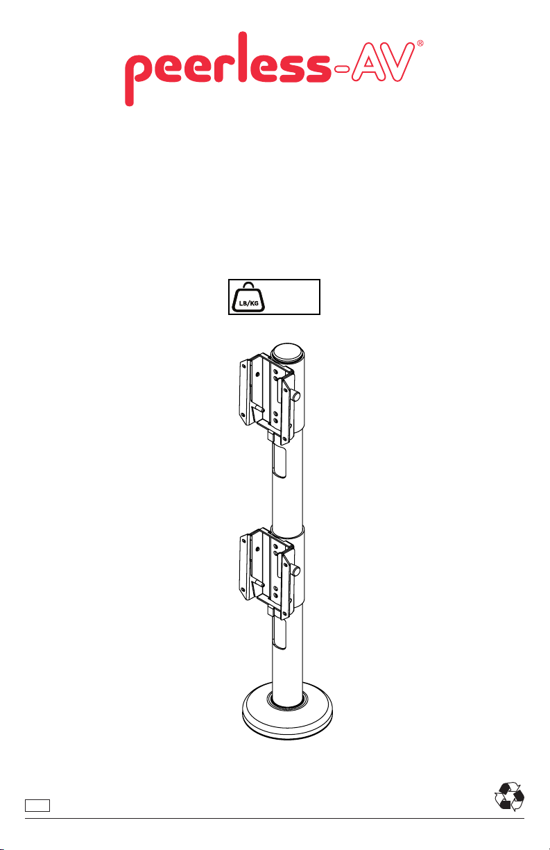
B-MIS38426
For Samsung Super Ultra Wide Curved Monitor
43": LC43J890DKNXZA
49": C49HG90DMN
49": LC49J890DKNXZA
60 lb
MAX
(27 kg)
ENG
1
2019-08-26 #:090-9217-1
Page 2

WARNING
ENG - Before installing make sure the supporting surface will support the combined load of the equipment and
hardware. Screws must be tightly secured. Do not overtighten screws or damage can occur and product may fail.
Never exceed the Maximum Load Capacity. Always use an assistant or mechanical lifting equipment to safely lift
and position equipment. This product is intended for indoor use only. Use of this product outdoors could lead to
product failure or personal injury. Be careful not to pinch ngers when operating the mount. For support please
call customer care at 1-800-865-2112.
ENG
Symbols
ENG
ENG
Do not overtighten screws.
ENG
Listen
ENG
Tools Needed for Assembly.
3/8"
(10mm)
WARNING
ENG
ENG
Display center.
#
Skip to step.
ENG
1
2
3
x3
Screws must get at least three
ENG
full turns and t snug.
To properly tighten screws: Tighten until screw
head makes contact, then tighten another 1/2
turn. Do not overtighten screws.
+1/2
17/64" 5/8", 7/16"
3/32"
2"-3"
4
2
2019-08-26 #:090-9217-1
Page 3
ENG
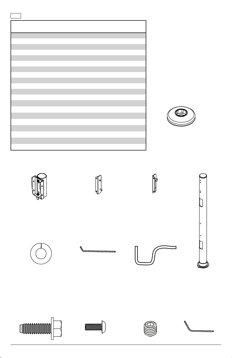
Parts (Before beginning, make sure you have all parts shown below).
Parts List
A desktop swivel base 1 090-1821
B adaptor bracket 2 091-1211
C right adaptor bracket 2 091-1217
D left adaptor bracket 2 091-1218
E support tube 1 091-1221
F M6 x 6mm hex set screw 2 510-9150
G M4 x 10mm socket pin screw 8 520-1060
H slope nut 3 530-0035
I 1/4-20 x 3/4" washer head screw 4 520-1321
J 1/4" x 1/2" x .068 split washer 4 540-9402
K 4mm allen wrench 1 560-9646
L 48" foam strip 1 570-1170
M 1/4-20 lock nut 4 530-1021
N fender washer 4 540-1008
O 1/4-20 x 3" threaded rod 4 520-2585
P base plate 1 090-1544
Q thrust washer 1 590-1287
R 1/4-20 x 1.5" threaded rod 4 520-2250
S 3mm allen wrench 1 560-0194
T 10-32 x 1/2" set screw 2 520-1614
Part #Description Qty
A (1)
desktop swivel base
B (2)
adaptor bracket
J (4)
1/4" x 1/2" x .068 split washer
I (4)
1/4-20 x 3/4" washer
head screw
C (2)
right adaptor bracket
K (1)
4mm allen wrench
G (8)
M4 x 10mm socket pin
screw
D (2)
left adaptor bracket
L (1)
48" foam strip
F (2)
M6 x 6mm hex set
screw
E (1)
support tube
S (1)
3mm allen wrench
3
2019-08-26 #:090-9217-1
Page 4
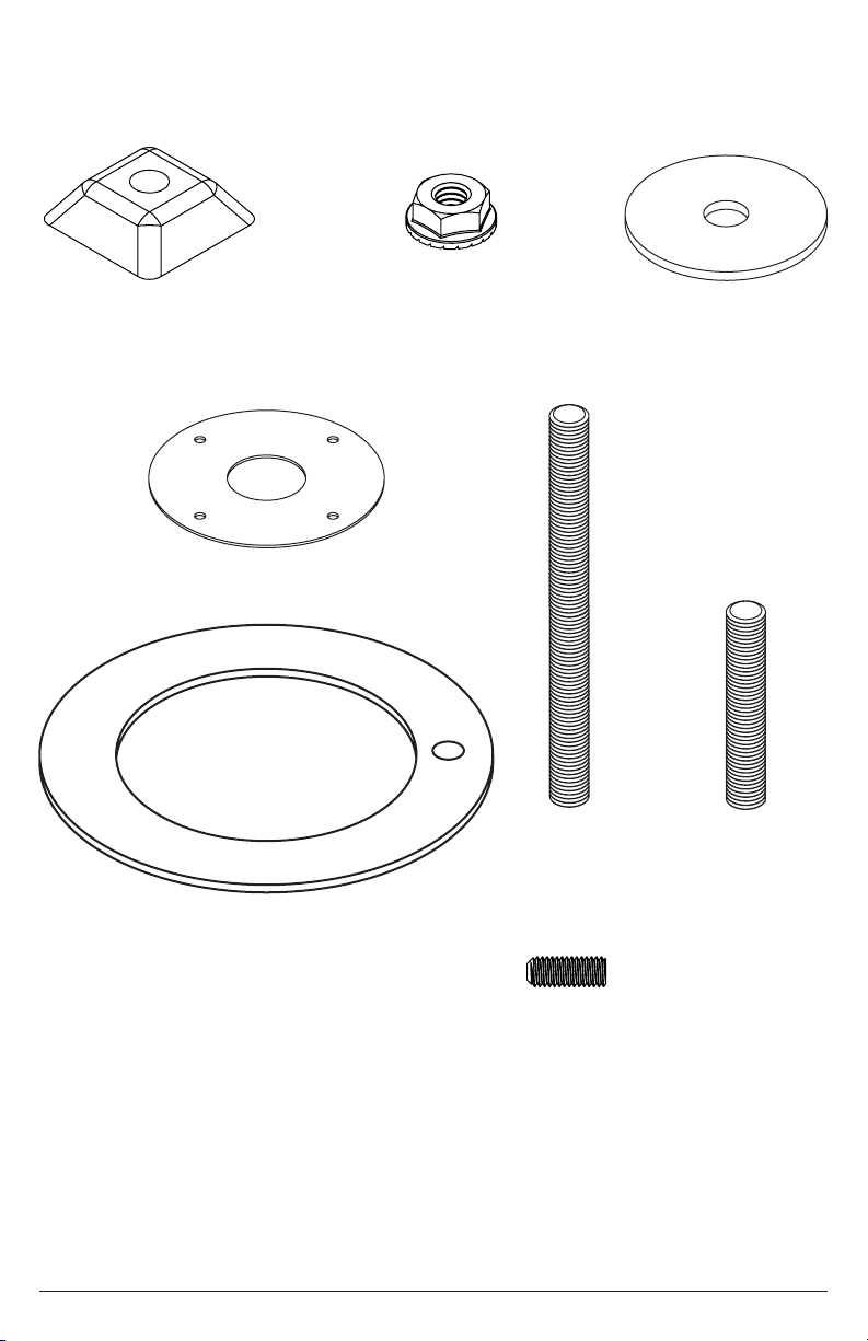
H (3)
slope nut
M (4)
1/4-20 lock nut
N (4)
fender washer
P (1)
base plate
Q (1)
thrust washer
O (4)
1/4-20 x 3" threaded rod
R (4)
1/4-20 x 1.5" threaded rod
T (2)
10 x 32mm x 1/2"
hex set screw
4
2019-08-26 #:090-9217-1
Page 5
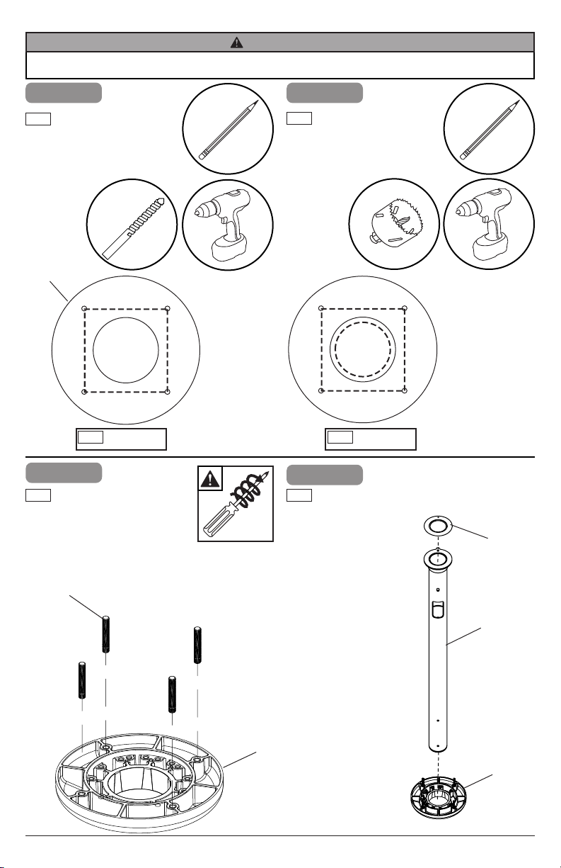
WARNING
ENG - Wooden mounting surface requires a minumum of 3/4" thickness to hold screen securely.
1
ENG
Use base plate as a
template to mark location
of holes. Drill four holes in
square formation, aligned
to front of desk.
P
ENG
2
ENG
Threaded rods
must fasten a
minimum of three
turns.
17/64"
Front of desk
x3
1-1
Drill 2" to 3" cord
ENG
managment hole in the
center of the square
formation.
ENG
2-1
ENG
Turn base
upside down.
2"-3"
Front of desk
Q
O (4)
OR R (4)
A
E
A
5
2019-08-26 #:090-9217-1
Page 6

180°
210°
210°
30°
60°
0°
120°
180°
240
3
ENG
Swivel restriction: refer to detail 1 through 4. Fasten two set screws
where indicated below to the outside of desired angle in steel base.
Note: set screws must be bottomed out into base.
3/32"
ENG
210°
Front
30°
Detail 1
210°
E
0°
60°
120°
Detail 2
Q
A
Detail 3
°
40°
Detail 4
6
2019-08-26 #:090-9217-1
240°
Page 7

WARNING
ENG - Make sure that the supporting surface will safely support the combined load of the equipment and all
attached hardware and components.
CAUTION
ENG - Installations to desktops that have a gap between two supporting boards are not acceptable mounting
surfaces for the desktop swivel mount.
4
ENG
Align plate with threaded rods.
Note: Washer must be centered.
P
Q
A
E
4-1
7/16"
(11mm)
ENG
Align base assembly with
supporting surface and base
pattern facing the front as
shown. Tighten four fender
washers with four lock nuts
in the sequenced pattern
at minimum ush with the
bottom of the threaded rods.
ENG
Front
N (4)
ENG
Front
3
2
1
4
7
M (4)
2019-08-26 #:090-9217-1
Page 8

5
ENG
Optional: for added security replace two of the
washers and locknuts with slope nuts. Hand
tighten slope nuts onto two of the threaded rods
until snug against bottom of desk as shown.
ENG
Bottom of desk
5-1
ENG
Thread another slope nut upside-down,
about two turns from rst slope nut as
shown. Avoid jamming both slope nuts
together, doing so may make it dicult
to remove slope nut used for tightening.
ENG
Bottom of desk
H
O
5-2
ENG
Insert an open end wrench
between both slope nuts and tighten as shown.
After top slope nut is secure remove bottom slope
nut as shown.
ENG
Leave space
between
slope nuts.
5-3
ENG
After slope nut is
secure, remove bottom
slope nut as shown.
ENG
Bottom of desk
5/8"
ENG
Tightening
slope nut
H
8
2019-08-26 #:090-9217-1
Page 9

6
6-1
J (4)
I (4)
B (2)
3/8"
(10mm)
6-2
S
F(2)
E
9
2019-08-26 #:090-9217-1
Page 10

7
ENG
Note orientation of tab
ENG
Samsung Super Ultra Wide Curved Monitor
43" (LC43J890DKNXZA), 49" (C49HG90DMN), 49" (LC49J890DKNXZA)
sold separately
ENG
Top display
7-1
ENG
Note orientation of tab
10
ENG
Bottom display
2019-08-26 #:090-9217-1
Page 11

8
G (4)
D
C
ENG
K
Top display
8-1
G(4)
D
C
11
ENG
Bottom display
2019-08-26 #:090-9217-1
Page 12

9
ENG
Attach foam strip to the top edge of
bottom display.
L
L
12
L
2019-08-26 #:090-9217-1
Page 13

10
ENG
Attach top display rst.
ENG
Top view
10-1
ENG
Attach bottom display.
C
ENG
D
B
Top view
13
C
D
B
2019-08-26 #:090-9217-1
Page 14

WARNING
Must support weight/front of display when disengaging
ENG
quick release knobs from support tube.
11
ENG
QUICK RELEASE; Pull knobs to disengage.
11-1
ENG
Support display, tilt forward.
14
2019-08-26 #:090-9217-1
Page 15

12
ENG
Optional: cable management
15
2019-08-26 #:090-9217-1
Page 16

Peerless Industries, Inc. (“Peerless-AV”) warrants to original end-users that each Peerless-AV® mounting product will be free from defects
LIMITED FIVE-YEAR WARRANTY
in material and workmanship, under normal use, for the applicable warranty period (from date of the original installation of the product).
At its option, Peerless-AV will repair or replace, or refund the purchase price of, any product which fails to conform with this warranty.
Any implied warranty of merchantability or tness for a particular purpose shall be limited to the period of the
express warranty set forth below.
In no event shall Peerless-AV be liable for incidental or consequential damages, whether or not secured by a
security device which may be included with the product.
Some states do not allow limitations on how long an implied warranty lasts, or the exclusion of incidental or consequential damages, so
the above limitation and/or the above exclusion may not apply to you.
This warranty does not cover damage caused by incorrect selection, installation or the failure to follow Peerless-AV instructions or
warnings when installing, using or storing the product.
This warranty gives specic legal rights, and you may also have other rights which vary from state to state. To make a warranty claim in
North America, contact Peerless-AV customer care at 1-800-865-2112. See complete global warranty information for regions outside North
America at www.peerless-av.com/en-uk/customer-care/warranties-returns.
Peerless-AV
2300 White Oak Circle
Aurora, IL 60502
Email: tech@peerlessmounts.com
Ph: (800) 865-2112
Fax: (800) 359-6500
www.peerless-av.com
© 2019, Peerless Industries, Inc.
Peerless-AV Europe
Unit 3 Watford Interchange,
Colonial Way, Watford, Herts,
WD24 4WP, United Kingdom
Customer Care
44 (0) 1923 200 100
www.peerless-av.com
© 2019, Peerless Industries, Inc.
Peerless-AV de Mexico
Ave de las Industrias 413
Parque Industrial Escobedo
Escobedo N.L Mexico 66062
Servicio al Cliente
01-800-849-65-77
www.peerless-av.com
© 2019, Peerless Industries, Inc.
 Loading...