

Page 1

User Manual and Installation Guide
Amplifi er
Models:
ADS100-A252
ISSUED: 10-07-13 SHEET #: 180-9052-1
Page 2
Page 3

Contents
Important Safety Instructions ......................................................................................................... 4
Introduction ...................................................................................................................................... 6
Installation Planning ...................................................................................................................... 6
What’s In ADS100-A252 Box......................................................................................................... 6
Tools Needed For Installation ........................................................................................................ 6
Installation ........................................................................................................................................ 7
Product Overview .......................................................................................................................... 7
Installing IN-WALL the ADS100-A252 Wireless Receiver/Amplifi er .............................................. 8
Transmitter and Amplifi er Pairing .................................................................................................. 9
Returning To Finish The Installation .............................................................................................. 9
Stereo VS Mono Setup ................................................................................................................ 10
Multiple Amplifi ers to Same Inputs .............................................................................................. 10
Power Outages ............................................................................................................................ 10
Limited Warranty ............................................................................................................................11
3 of 12
ISSUED: 10-07-13 SHEET #: 180-9052-1
Page 4
Important Safety Instructions
Warnings/Safety
1. Read these instructions
2. Keep these instructions
3. Heed all warnings
4. Follow all instructions.
5. Do not use this apparatus near water.
6. Clean only with dry cloth.
7. Do not block any ventilation openings. Install in accordance with manufacturer’s instructions.
8. Do not install near any heat sources such as radiators, heat registers, stoves, or other apparatus
(including amplifi ers) that produce heat.
9. Do not defeat the safety purpose of the polarized or grounding-type plug. A polarized plug has two
blades with one wider than the other. A grounding type plug has two blades and a third grounding
prong. The wide blade or the third prong are provided for your safety. If the provided plug does not fi t
into your outlet, consult an electrician for replacement of the obsolete outlet.
10. Protect the power cord from being walked on or pinched particularly at plugs, convenience
receptacles, and the point where they exit from the apparatus.
11. Only use attachments/accessories specifi ed by the manufacturer.
12. Use only with the cart, stand, tripod, bracket, or table specifi ed by the manufacturer, or sold with
the apparatus. When a cart is used, use caution when moving the cart/apparatus combination to
avoid injury from tip-over.
13. Unplug this apparatus during lightning storms or when unused for long periods of time.
14. Refer all servicing to qualifi ed service personnel. Servicing is required when the apparatus has
been damaged in any way, such as power-supply cord or plug is damaged, liquid has been spilled or
objects have fallen into the apparatus, the apparatus has been exposed to rain or moisture, does not
operate normally, or has been dropped.
15. The product was submitted and evaluated for use at the maximum ambient (Tma)ἁ 40°C
16. WARNING: To reduce the risk of fi re or electrical shock do not place this apparatus in a position
where it is exposed to dripping or splashing liquid, rain, moisture, or exceedingly high humidity.
Objects containing liquid shall not be placed in proximity to the unit such that they present a risk of
spillage onto the apparatus.
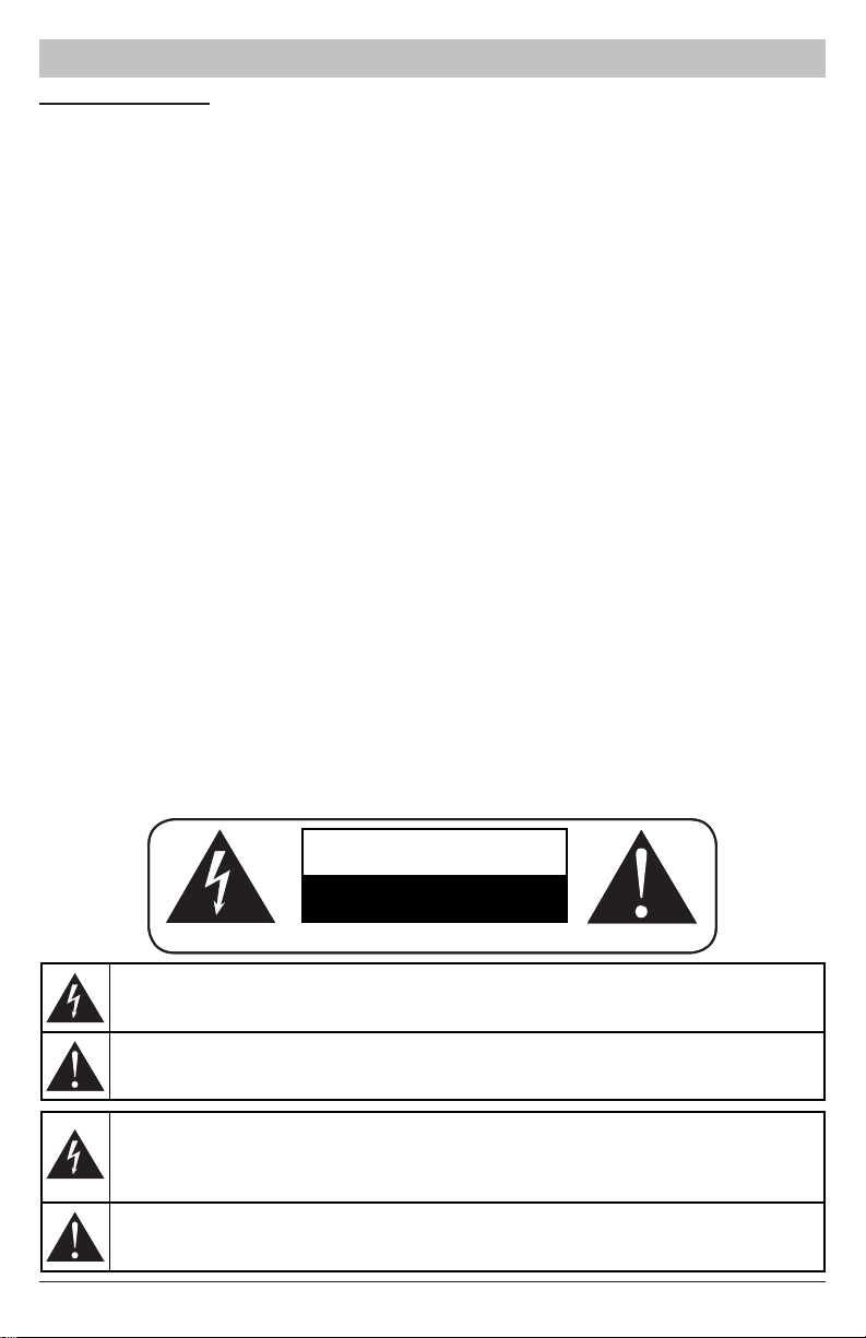
CAUTION
RISK OF ELECTRIC SHOCK!
DO NOT OPEN!
ATTENTION ! RISQUE DE CHOC ! ÉLECTRIQUE PAS OUVRIR !
The lightning fl ash with arrowhead symbol, within an equilateral triangle, is intended to alert
the user to the presence of uninsulated dangerous voltage within the product's enclosure
that may be a suffi cient magnitude to constitute a risk of electric shock to persons.
The exclamation point within an equilateral triangle is intended to alert the user to the
presence of important operating and maintenance (servicing) instructions in the literature
accompanying the appliance.
Le symbole de l'éclair avec une fl èche à son extrémité, dans un triangle équilatéral, a pour
but de vous avertir de la présence d'une « tension électrique dangereuse » et non isolée à
l'intérieur de l'enceinte de l'appareil, qui peut être suffi samment puissante pour constituer
un risque d'élctrocution pour les personnes
Le point d'excalamation dans un triangle équilatéral vous avertit de l'existence d'instructions
importantes de fonctionnement et d'entretien (intervention) dans la documnetation
accompagnant l'appareil.
4 of 12
ISSUED: 10-07-13 SHEET #: 180-9052-1
Page 5

Important Safety Instructions
17. To avoid electric shock, never stick anything in the slots on the case or remove the cover.
18. This product is intended for indoor use only.
Model:ADS100-A252
FCC ID: 2AAW2ADS100-A252
This device complies with part 15 of the FCC Rules. Operation is subject to the following two
conditions: (1) This device may not cause harmful interference, and (2) this device must accept any
interference received, including interference that may cause undesired operation.
5 of 12
ISSUED: 10-07-13 SHEET #: 180-9052-1
Page 6

Introduction
This instruction sheet is meant for adding additional amplifi ers to the base system and presume one
amplifi er is already set up and running per instructions provided.
This wireless audio distribution system provides for 8 total independent mono zones, or 4 total stereo
zones, or any combination in-between. By connecting your source(s) to either the RCA line level
or speaker level inputs, you can wirelessly receive the audio signal and amplify it for the remote
speakers.
The installation process starts with a little planning, understanding the options you have for
installation.
Installation Planning
There is much fl exibility in the component installations. The amplifi er/receiver also has installation
options including:
• Inside a drywall cavity (fl ush to the outer surface). The maximum drywall thickness is 5/8”.
• Attached to a structure, such as ceiling beams
• On top of a wall surface (requires accessory kit ADS100-OWK)
It helps to have your amp locations in mind when starting the installation process. Generally the
amplifi er is placed near to a 120/240 VAC power source, capable of 150 watts peak demand.
Tip: While this device does not require Line-of-Sight, the signal still can be affected by certain
building materials. For best wireless performance, try to keep cement or a lot of steel (like ductwork
or a refrigerator) out of the imaginary Line-of-sight between transmitter and receivers.
What’s In The ADS100-A252 Box
Before you start the installation, make sure you have the following items:
• ADS100-A252 Amplifi er Kit
• Amplifi er In/On-Wall, 25X2, 120/240V
• In-Wall Holder For Amp
• In-Wall Bracket Screw For Amp
• Drywall Clamp
• Conduit Adapter Bracket
• 2 Gang Oversize Wall Plate
• In-Wall Amp Template
• System Instructions
Tools Needed For Installation
• Bubble Level
• Phillips Screwdriver
• Small straight screwdriver
• Drywall Saw
• Wire Strippers
• Side Cutters
• Tape Measure
• Pencil
6 of 12
ISSUED: 10-07-13 SHEET #: 180-9052-1
Page 7

Installation
Product Overview
Front
1
1. RX MODULE
• Insert RXS or RXM Module here
2. POWER INDICATOR
• Blue when power is on.
Back
1
2
2
1. Power Connector
2. Speaker Connector
7 of 12
ISSUED: 10-07-13 SHEET #: 180-9052-1
Page 8

Installation
Installing IN-WALL the ADS100-A252 Wireless Receiver/Amplifi er
Step 1
Locate area that In-Wall amp will be installed.
Step 2
Conduct a stud search to investigate wall stud layout to verify mounting of amplifi er and speaker
placement. For In-Wall Amplifi er scenario, the installer will want to choose a stud bay to mount within
which also provides access to the AC Outlet/Receptacle that will be used to tap on to power the
amplifi er.
Step 3
Once location for the stud placement is identifi ed, place IN-WALL Template on wall and ensure it is
level. Trace outline of template and cut away drywall for in-wall placement. The hole size is 4 1/8”
high x 4 3/16” wide.
Step 4
Using the access hole that has been cut, the installer will want to run the speaker lines to the speaker
locations decided upon. When conduit is required in UL2043 plenum rated areas, the installer will
then want to connect the accessory armored wire whip* (ADS100-PW) to the AC box through its
punch-outs located in-wall and attach this to the Conduit Adapter supplied. Or a standard fl exible
conduit whip may be used for non UL2043 plenum areas. Refer to local electrical code requirements.
Note: This step needs to be completed by a certifi ed electrician. When conduit is not required by
code, the user may use Romex or similar (at least 16 AWG shielded wire stranded or solid) routed
form the power source directly to the power input plug.
Step 5
Connect power at the amplifi er. For solid wire, simply strip back 1/4” insulation, and insert fi rmly into
the proper polarity cavity. For stranded wire, it’s recommended to twist the wire, and also use a small
straight screwdriver to release the clamp then insert the wire. Test all connections by trying to pull the
wire back out.
Step 6
Connect speaker wires to the speaker terminal plug. Strip 3/16” insulation off the speaker wires,
loosen the screw clamp, insert the wire, tighten screw clamp. Be sure to follow the positive (left) and
negative (right) nomenclature.
Step 7
Take the ADS100-RXS Stereo RX module and plug into the port on the amplifi er. Install the locking
screw through the RX module into the amplifi er.
Step 8
The installer will want to leave the amp out of the wall to verify pairing has taken place between the
TX and the RX. Once pairing can be verifi ed, the amp can then be installed in the wall.
Step 9
Skip to "Transmitter and Amplifi er Pairing" next section
8 of 12
ISSUED: 10-07-13 SHEET #: 180-9052-1
Page 9

Transmitter and Amplifi er Pairing
The following presumes at least 1 amplifi er is already paired with the transmitter.
Step 1
Apply power to the ADS100-T8 transmitter by pressing the power button on the front left. The two
right side front face LED’s will illuminate red. The audio source(s) also should be present and on,
and connected to inputs 1-4 at least. A portable music player with rca outputs can be used also for
channel assignment.
Step 2
Apply power to the amplifi er(s) installed. Also ensure the speakers are connected, or at least a single
speaker. Both blue LED’s will blink about every second.
Step 3
At the transmitter face, depress the "SYNC 1-4" button once. The face LED and TX LED will both
blink allowing 2 minutes to sync the appropriate amplifi er. This allows any and all 4 inputs matched
to that TX module to be synced. If not synced, resumes previous assignment. The process can start
again.
Step 4
At the amplifi er, press “Sync” button once. The blue LED wills top blinking indicating it has locked onto
the TX module. If not on the input channel desired, press the “CH-SEL” button to scroll through the
inputs to fi nd the correct one(s). LED on transmitter face and TX module will illuminate solid blue to
indicate successful pairing.
Step 5
Repeat the above procedure for additional amplifi ers. Each amplifi er needs to be synced from start to
fi nish as above. Return to the amplifi er to fi nish the installation.
Returning To Finish The Installation
Step 1
Install the Drywall Clamps onto each side of the amplifi er using the center slot.
Step 2
Feed the amplifi er though the wall cut out, using the oval cutouts on the holding bracket with your
fi ngers. Guide the amp in and toward the wiring fi rst, then back up so the top of the holding bracket is
outside of the wall, then pull out slightly and drop down onto cut out bottom edge. The holding bracket
should be outside but fl ush to the drywall surface.
Step 3
Snug clamp screws to secure the amp.
Step 4
Attach 2 gang cover plate to amplifi er holding bracket.
9 of 12
ISSUED: 10-07-13 SHEET #: 180-9052-1
Page 10

Stereo VS Mono Setup
The amplifi er is fi xed 2 channel operation. When Mono operation is used (by using a ADS100-RXM
module, sold separately) the receiver syncs to only 1 channel/input at the transmitter. However
both amplifi er speaker outputs will have mono output and can be used. Bridging for more power
to one output is not possible. The amplifi er is confi gured as Stereo or Mono by utilizing the proper
RX module. The system is supplied with the ADS100-RXS with is the stereo 2 channel module. For
Mono, the accessory part ADS100-RXM is utilized. Simply plug the ADS100-RXM RX Module into
the amplifi er instead of the ADS100-RXS. The Sync process is the same with Mono as with Stereo
modules. The only difference being, when the “Ch-Sel” button is pressed, it scrolls through transmitter
inputs 1 at a time, not 2 at a time.
MULTIPLE AMPLIFERS TO SAME INPUTS
This system has the ability for multiple Receiver/Amplifi ers to be paired to the same transmitter
inputs. I.E. pair four stereo amplifi ers to transmitter inputs 1 and 2. The limit to maintain the highest
QOS is two stereo or four mono signals per TX module. More can be done but the QOS will go down,
however installation situation and environment might allow more to work.
POWER OUTAGES
Once paired and set up per the installation requirements, the transmitter module, and receiver
modules will remember their paired channels should the power be removed from part or all of the
system. The power-on and re-sync takes about 1 second from when power is restored.
10 of 12
ISSUED: 10-07-13 SHEET #: 180-9052-1
Page 11

Limited Warranty
Peerless Industries, Inc. (“Peerless-AV®”) warrants to original end-users of Peerless-AV® products
that Peerless-AV® products will be free from defects in material and workmanship, under normal use,
for the periods listed below, from the date of purchase by the original end-user. At its option, PeerlessAV® will repair or replace with new or refurbished products or parts, or refund the purchase price of,
any Peerless-AV™ product which fails to conform with this warranty.
In no event shall the duration of any implied warranty of merchantability or fi tness for a
particular purpose be longer than the period of the applicable express warranty set forth
above. Some states do not allow limitations on how long an implied warranty lasts, so the above
limitation may not apply to you.
This warranty does not cover damage caused by (a) service or repairs by the customer or a person
who is not authorized for such service or repairs by Peerless-AV®, (b) the failure to utilize proper
packing when returning the product, (c) incorrect installation or the failure to follow Peerless-AV®’s
instructions or warnings when installing, using or storing the product, or (d) misuse or accident,
in transit or otherwise, including in cases of third-party actions and force majeure. This warranty
also does not cover corrosion or rust resulting from damaged, scratched or chipped paint or other
surfaces.
In no event shall Peerless-AV® be liable for incidental or consequential damages or damages
arising from the theft of any product, whether or not secured by a security device which may
be included with the Peerless-AV® product. Some states do not allow the exclusion or limitation of
incidental or consequential damages, so the above limitation or exclusion may not apply to you.
This warranty is in lieu of all other warranties, express or implied, and is the sole remedy with respect
to product defects. No dealer, distributor, installer or other person is authorized to modify or extend
this Limited Warranty or impose any obligation on Peerless-AV® in connection with the sale of any
Peerless-AV® product.
This warranty gives specifi c legal rights, and you may also have other rights which vary from state to
state.
Product Warranty Period
Mounts 5 years
Furniture 1 year
Cables 25 years
Cleaning Products 1 year
Electronic Products and components 1 year
11 of 12
ISSUED: 10-07-13 SHEET #: 180-9052-1
Page 12

Peerless -AV
2300 White Oak Circle
Aurora, IL 60502 USA
peerair.peerless-av.com
©2013 Peerless-AV. All rights reserved. Peerless-AV is a trademark of Peerless Industries, Inc.
Other parties’ marks are the property of their respective owners.
 Loading...