

Page 1
RQ™4300 Series
Page 2
2
Intended to alert the user to the presence of uninsulated “dangerous voltage” within the product’s
enclosure that may be of sufficient magnitude to constitute a risk of electric shock to persons.
Intended to alert the user of the presence of important operating and maintenance (servicing)
instructions in the literature accompanying the product.
CAUTION: Risk of electrical shock — DO NOT OPEN!
CAUTION: To reduce the risk of electric shock, do not remove cover. No user serviceable parts inside. Refer
servicing to qualified service personnel.
WARNING: To prevent electrical shock or fire hazard, do not expose this appliance to rain or moisture. Before
using this appliance, read the operating guide for further warnings.
Este símbolo tiene el propósito, de alertar al usuario de la presencia de “(voltaje) peligroso” sin aislamiento dentro de la caja del producto y que puede tener una magnitud suficiente como para constituir
riesgo de descarga eléctrica.
Este símbolo tiene el propósito de alertar al usario de la presencia de instruccones importantes sobre la
operación y mantenimiento en la información que viene con el producto.
PRECAUCION: Riesgo de descarga eléctrica ¡NO ABRIR!
PRECAUCION: Para disminuír el riesgo de descarga eléctrica, no abra la cubierta. No hay piezas útiles dentro.
Deje todo mantenimiento en manos del personal técnico cualificado.
ADVERTENCIA: Para evitar descargas eléctricas o peligro de incendio, no deje expuesto a la lluvia o humedad
este aparato Antes de usar este aparato, Iea más advertencias en la guía de operación.
Ce symbole est utilisé dans ce manuel pour indiquer à l’utilisateur la présence d’une tension dangereuse
pouvant être d’amplitude suffisante pour constituer un risque de choc électrique.
Ce symbole est utilisé dans ce manuel pour indiquer à l’utilisateur qu’il ou qu’elle trouvera d’importantes
instructions concernant l’utilisation et l’entretien de l’appareil dans le paragraphe signalé.
ATTENTION: Risques de choc électrique — NE PAS OUVRIR!
ATTENTION: Afin de réduire le risque de choc électrique, ne pas enlever le couvercle. Il ne se trouve à l’intérieur
aucune pièce pouvant être reparée par l’utilisateur. Confiez I’entretien et la réparation de l’appareil à un réparateur
Peavey agréé.
AVERTISSEMENT: Afin de prévenir les risques de décharge électrique ou de feu, n’exposez pas cet appareil à la
pluie ou à l’humidité. Avant d’utiliser cet appareil, lisez attentivement les avertissements supplémentaires de ce
manuel.
Dieses Symbol soll den Anwender vor unisolierten gefährlichen Spannungen innerhalb des Gehäuses
warnen, die von Ausreichender Stärke sind, um einen elektrischen Schlag verursachen zu können.
Dieses Symbol soll den Benutzer auf wichtige Instruktionen in der Bedienungsanleitung aufmerksam
machen, die Handhabung und Wartung des Produkts betreffen.
VORSICHT: Risiko — Elektrischer Schlag! Nicht öffnen!
VORSICHT: Um das Risiko eines elektrischen Schlages zu vermeiden, nicht die Abdeckung enfernen. Es befinden
sich keine Teile darin, die vom Anwender repariert werden könnten. Reparaturen nur von qualifiziertem
Fachpersonal durchführen lassen.
ACHTUNG: Um einen elektrischen Schlag oder Feuergefahr zu vermeiden, sollte dieses Gerät nicht dem Regen
oder Feuchtigkeit ausgesetzt werden. Vor Inbetriebnahme unbedingt die Bedienungsanleitung lesen.
Page 3

RQ™4300 SERIES
Reference Quality Recording and Sound Reinforcement Console
INTRODUCTION
Thank you for purchasing the RQ 4300 Series mixing console. The RQ 4300 represents years of
experience in mixer engineering and offers incredible versatility through its flexible 13-bus design.
Its impressive 4 SUB GROUPS, 6 AUX, L/R and MONO outputs place the RQ 4300 in a league of
its own. Additionally, each SUB group features a high-quality dynamic compressor that can be used
on the corresponding SUB mix, or can be patched to any channel INSERT. Compact package
design and rugged construction make the RQ 4300 ideal for “the road” or for permanent
installations. Covering both the RQ 4324 and the RQ 4332, this guide describes the features and
controls found on your new mixer:
• 24 (RQ 4324) or 32 (RQ 4332) input channels; each with GAIN, EQ, AUX and PAN controls,
as well as SUB, L/R and MONO assign buttons
• Low-noise mic preamps and XLR connectors on each channel
• Balanced 1/4" LINE inputs on CHANNELS 1-22 (RQ 4324) or 1-30 (RQ 4332)
• INSERT jacks on CHANNELS 1-20 (RQ 4324) or 1-28 (RQ 4332)
• Innovative chassis design with recessed back panel connectors (ideal for desktop placement)
• Smooth, 60 mm CHANNEL, SUB, L/R and MONO faders
• Phantom power with separate activation switches and LEDs indicating operation on
CHANNELS 1-16 or 17-24 (RQ 4324); 1-24 or 25-32 (RQ 4332)
• 2 SUPER CHANNELS with PAD (-20 dB) and POLARITY buttons
• 2 STEREO CHANNELS with 1/4" and RCA connectors
• 6 AUX sends (4 balanced XLR)
• 4 SUB groups with patchable dynamic compressors
• MUTE and PFL buttons, clip (PK) and signal (SIG) LEDs on all input channels
• Two RETURNs, each with switchable low-cut (150 Hz) filter, level control, bus assignment,
mute and AFL
• PFL on all input channels
• AFL on all AUX SEND, RETURN, SUB and MONO channels
• Stereo HEADPHONE output
• BALANCED XLR and UNBALANCED 1/4" outputs for MONO, LEFT and RIGHT
• LEFT, RIGHT and MONO master INSERTS
• SUB group and MASTER CLIP LEDs sample at summing amp and post-FADER
EXPLANATION OF TERMS
BUSES – The signal paths through the mixer from the channels to the various outputs. The RQ
4300 Series mixer contains 13 different buses: L, R, MONO, SUBS 1-4, AUX 1-6.
SUB groups – The buses used to group channels together. This allows one fader to control a
submix of many channels.
AUX sends – The buses used to route signals to effects and monitors from each channel. PRE
means AUX level is not affected by fader setting; POST means AUX level is affected by fader
setting.
3
ENGLISH
Page 4

PFL – PRE-FADER LISTEN. PFLs send signals to the headphone output and are not affected by
the fader setting.
AFL – AFTER-FADER LISTEN. AFLs send signals to the headphone output and are affected by
fader setting.
LOW CUT – (channel low cut). These adjust the frequency in the channel where the low frequencies
begin to roll off, and are variable by frequency from OFF (inaudible) to 300 Hz.
1/2, 3/4, L/R, MONO – These buttons route the channels to their respective output buses. BAL/PAN
determines 1/2, 3/4 or L/R.
INSERTS – These jacks allow the signal to be taken from and returned to the channel, allowing
outboard equipment to be inserted into the signal chain.
MID FREQ – This control selects the frequency adjusted by the MID control in the EQ
section.
COMPRESSORS – These reduce levels at a ratio of 4 to 1 when the THRESHOLD is reached.
THRESHOLD – This control sets the level at which compression activates.
GAIN – This control sets the output level from the compressor. This is really a
makeup gain, allowing the user to recover gain lost by compression.
LINK – When these buttons are depressed, the input to compressor 1 activates
compressors 1 and 2, and the input to compressor 3 activates compressors 3 and 4.
SUBGROUP/EXTERNAL – This button routes the compressor signal to the compressor
output jack (LED indicates external jack). This jack is wired reverse of an insert jack, allowing
the compressor to be patched with a 1/4" TRS cable.
PHANTOM POWER – Provides +48 Volt power to microphones that need it.
CONNECTOR WIRING
Unless otherwise stated, all input and output jacks are wired as follows:
XLR (MIC) – Pin 1 = GROUND
Pin 2 = POSITIVE
Pin 3 = NEGATIVE
TS and TRS – Tip = POSITIVE (SEND)
Ring = NEGATIVE (RETURN)
Sleeve = GROUND
RCA
(PHONO) – Tip = POSITIVE
Cup = GROUND
UNPACKING
Inspect the console carefully during unpacking. If you find any damage, notify your dealer
immediately. Be sure to save the carton and all packing materials. Should you ever need to ship the
unit back to Peavey Electronics, one of its service centers, or the dealer; use only the original
factory packing.
4
Page 5
STANDARD CHANNELS
[CHANNELS 1 — 20 (RQ 4324) AND 1 — 28 (RQ 4332)]
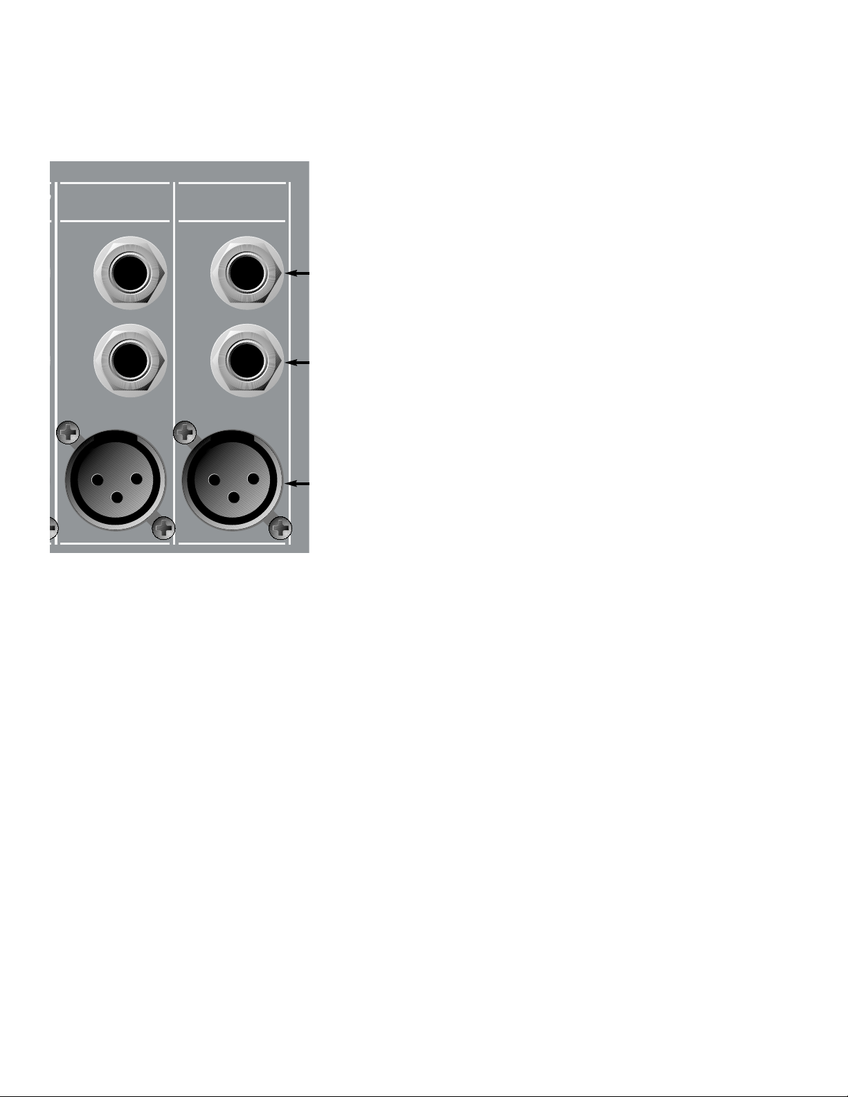
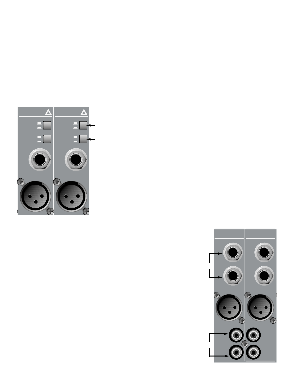
REAR PANEL CONNECTIONS (1) INSERT
This jack is a 1/4" Tip/Ring/Sleeve (TRS)
connection that allows a pre-EQ, pre-fader
signal to be taken from and returned to the
channel. Insert jacks are often used to route
an input signal to an external signal processor.
The RQ 4300’s on-board compressors can
be patched to any channel with an INSERT.
(2) LINE
This jack is a 1/4" balanced (TRS) high
impedance input for high level signals. The tip
is the positive input, which should also be
used for unbalanced inputs. This input is
connected through a 20 dB pad to the MIC
input (3). The two inputs cannot be used
simultaneously.
(3) MIC
This jack is a balanced XLR (3-pin) lowimpedance connection intended for
microphones. Other low-impedance signals
such as instruments sent to the console via
direct boxes will also utilize these inputs.
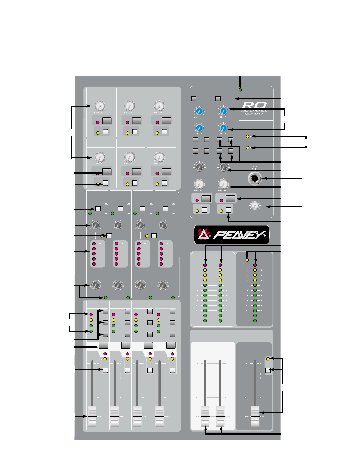
CHANNEL STRIP CONTROLS
(4) GAIN
This control varies the input gain of the channel to provide a wider dynamic range. The
adjustment range is +10 dB to +58 dB for the XLR input and –10 dB to +38 dB for the line
input. Proper adjustment of input gain maximizes signal-to-noise ratio. Optimum gain setting
can be achieved by depressing the PFL switch (15) and adjusting the GAIN control until the
signal occasionally illuminates the 0 dB LED in the AFL/PFL display (45).
(5) LOW CUT
This control adjusts the setting of the low-cut filter. Variable from no cut to cut below 300 Hz,
this feature reduces/eliminates extremely low frequencies that cause “low-end rumble,” and is
a very effective tone shaping tool. It can also be used to reduce the “boominess” sometimes
encountered with male voices.
(6) HI
This active tone control is a shelving-type that varies high-frequency response by +/-15 dB in
the range above 12 kHz.
(7) MID
This active tone control is a bandpass (peak/notch) type that varies mid-frequency response
by +/-15 dB in a range from 200 Hz to 6 kHz.
5
T
3
2
1
IP=SEND RING=RETURN SLEEVE=GROUND)
12
INSERT
(TRS)
LINE
(BAL)
MIC
(BAL)
INSERT
(TRS)
LINE
(BAL)
MIC
(BAL)
Page 6
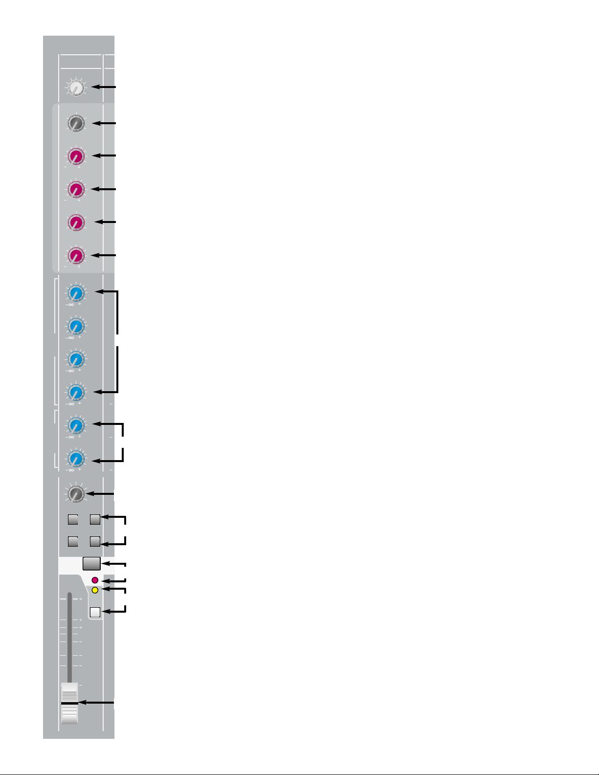
(8) MID FREQ
This control determines the center frequency of the MID control.
Center frequency for the bandpass filter can be set from 200 Hz
to 6 kHz.
(9) LOW
This active tone control is a shelving-type that varies low-frequency
response by +/-15 dB. Corner frequency is 75 Hz.
(10) AUX 1– 4
These controls adjust the level of the channel’s pre-fader signal that
is sent to the auxiliary mix. Gain is variable from minus infinity (– ∞)
to +10 dB. Unity gain is at the center detent position. Pre-fader
auxiliaries are typically used to send signal to stage monitors, but
can also be used to generate an independent recording mix.
NOTE: AUX SENDS 1-4 are factory set to deliver signal pre-EQ, but can
be modified (internally) to deliver signal post-EQ. Contact Peavey
Electronics Service Dept. for information. AUX SENDS 5-6 are always
post-EQ.
(11) AUX 5 – 6
These controls adjust the level of the channel’s post-fader signal
that is sent to the auxiliary mix. Gain is variable from minus infinity
(– ∞) to +10 dB. Unity gain is at the center detent position.
(12) PAN
This control determines the signal’s position with respect to L/R and
SUB 1– 4 outputs. Rotating the control counterclockwise increases
the amount of signal sent to L and odd-numbered SUBs; rotation
clockwise increases the amount sent to R and even-numbered
SUBs. For example, with the channel ASSIGN switch (13) in the
1/2 position, rotating the control counterclockwise increases the
amount of signal sent to SUB 1, while rotating clockwise increases
the amount sent to SUB 2. The C position sends equal amounts
to each.
(13) 1/2, 3/4, L/R, MONO (ASSIGN)
These post-fader, post-EQ switches determine where the channel
signal is being sent. For example, to send a signal to SUBs 1 & 2,
depress the 1/2 button. The PAN control (12) determines how much
signal is sent to each SUB group.
(14) MUTE SWITCH/MUTE-CLIP LED
This switch mutes all AUX, SUB, L/R and MONO sends from the
corresponding channel. This switch is equipped with a red LED that
will illuminate when the channel is muted. When the MUTE switch is
disengaged, the LED functions as a clip (PK) indicator that will
illuminate at 2 dB below clipping. Muting the channel does not
prevent the PFL signal from being sent to the PFL mix when the
PFL switch (15) is engaged.
(15) PFL SWITCH/SIGNAL-PFL LED
This switch connects the channel’s pre-fader signal to the PFL mix.
With this feature engaged, the channel’s signal can be monitored
through the headphones and/or on the AFL/PFL display. A yellow
6
1
4
5
6
7
8
9
12
16
10
11
13
14
15
5
64
37
2
9
1
010
10050
150
20
300
OFF
0
33
66
9
12
12
1515
0
33
66
9
12
12
1515
1K700
EQUALIZATION
2.5K
300
6K
200
0
33
66
9
12
12
1515
0
3
3
6
15
40
10
dB
0
3
3
6
15
40
10
dB
0
3
3
6
PREPOST
15
40
10
dB
0
3
3
6
15
40
10
dB
0
3
3
6
15
40
10
dB
0
3
3
6
15
40
10
dB
C
L
R
1/2 3/4
L/R MONO
CHANNEL
1
MUTE/
PK
10
6
3
0
6
12
20
30
8
9
9
9
5
5
5
5
5
5
GAIN
LOW
CUT
(Hz)
(dB)
MID
(dB)
MID
FREQ.
(Hz)
LOW
(dB)
AUX
AUX
AUX
AUX
AUX
AUX
PAN
SIG/
PFL
HI
1
2
3
4
5
6
Page 7
LED in the MONO MASTER section (45) will blink to indicate that the signal on the MONO
LED display and at the headphone out is PFL. Selecting PFL allows the operator to monitor a
channel even with the channel muted, and is especially useful for cueing CDs/tapes. When
the PFL button is in the out position, the yellow channel LED will blink as an indication of
signal presence (-20 dBu).
(16) CHANNEL FADER
This control varies the signal level sent from the channel to the L/R, SUB, and/or MONO
master channels from (– ∞) to +10 dB. The 0 position is unity gain, meaning no increase or
decrease in the level set by the GAIN control (4), and is the optimum setting for this control. If
the level is too quiet or too loud at unity gain on the FADER, the channel GAIN (4) may need
to be adjusted.
SUPER CHANNELS
[CHANNELS 21–22 (RQ 4324)
AND 29–30 (RQ 4332)]
Input connections and channel strip controls on SUPER
CHANNELS are the same as STANDARD CHANNELS with
the exception of INSERT jacks. In place of INSERT
connections, SUPER CHANNELS are equipped with:
(17) PAD
This switch attenuates (reduces) the input signal by 20 dB.
This allows accommodation of higher input levels without
clipping and is especially useful when close-miking high
sound pressure level (SPL) sources such as drums or guitar
cabinets. It is also beneficial for “hot” line sources such as
keyboards and some wireless microphones.
(18) POLARITY
This switch reverses the polarity of both the XLR and LINE input
connectors to compensate for an out-of-phase signal that would
otherwise cause frequency (phase) cancellations in the mix.
STEREO CHANNELS
[CHANNELS 23–24 (RQ 4324)
AND 31–32 (RQ 4332)]
STEREO CHANNELS offer the same channel strip controls as STANDARD
CHANNELS with the exception of the MID FREQ control (8). Center
bandpass frequency is set at 850 Hz. In place of the MID FREQ control,
STEREO CHANNELS offer independent gain controls for LINE and MIC
(XLR).
(19) STEREO 1/4" LINE INPUTS
These TS jacks are unbalanced line-level inputs for stereo (L/R)
signals. They are connected in parallel with the STEREO RCA
LINE INPUTS (20). If you have a MONO line source, use a Y
cable or one of the channels with a MONO line input.
7
17
18
19
20
22
0 dB
-20 dB
PAD
NORMAL
REVERSED
POLARITY
LINE
(BAL)
21
0 dB
-20 dB
PAD
NORMAL
REVERSED
POLARITY
LINE
(BAL)
MIC
MIC
(BAL)
MIC
(BAL)
24s
LEFT
RIGHT
MIC
(BAL)
23s
LEFT
RIGHT
MIC
(BAL)
LEFT
INPUT
RIGHT
INPUT
LEFT
INPUT
RIGHT
INPUT
Page 8
(20) STEREO RCA LINE INPUTS
These RCA (phono) inputs are unbalanced line-level inputs for stereo (L/R) signals. They are
connected in parallel with the STEREO 1/4" LINE INPUTS (19).
8
21
22
23
24
25
26
27
28
31
33
32
29
30
34
37
39
42
43
38
40
35
41
36
44
47
MASTER SECTION
45
48
46
6
12
GAIN
THRESHOLD
-5
CLIP
+6
0
-20
GAIN
(dB)
8
10
1
3
6
9
12
(dB)
LEFT
RIGHT
MONO
MUTE
SEND 3
SEND 6
AUX
3
6
15
40
MUTE/
PEAK
SIG/
AFL
AUX
3
6
15
40
MUTE/
PEAK
SIG/
AFL
COMPRESSOR I/O
SUBGROUP
4
2
LINK 3/4
-15 +5
-25 +15
-30 OFF
0 dBu (INPUT)
SUB 4
4
AUX
SEND 1
LEVEL
0
3
3
6
5
15
40
10
dB
MUTE/
PEAK
SIG/
AFL
AUX
SEND 4
0
LEVEL
3
3
6
5
15
40
10
dB
MUTE/
PEAK
SIG/
AFL
COMP 1 COMP 2 COMP 3 COMP 4
COMPRESSOR I/O
SUBGROUP
EXTERNAL
6
GAIN
(dB)
4
8
10
2
12
0
1
3
6
9
12
GAIN
REDUCTION
THRESHOLD
(dB)
-5
-15 +5
-25 +15
-30 OFF
0 dBu (INPUT)
SUB 1
CLIP
LEFT
+6
0
RIGHT
-20
MONO
1
MUTE
SEND 2
6
15
40
MUTE/
PEAK
SEND 5
6
15
40
MUTE/
PEAK
COMPRESSOR I/O
SUBGROUP
EXTERNAL
6
4
8
10
2
12
0
LINK 1/2
1
3
6
9
12
GAIN
REDUCTION
THRESHOLD
(dB)
-5
-15 +5
-25 +15
-30 OFF
0 dBu (INPUT)
SUB 2
CLIP
+6
0
RIGHT
-20
MONO
2
MUTE
AUX
3
SIG/
AFL
AUX
3
SIG/
AFL
GAIN
(dB)
LEFT
0
0
LEVEL
3
5
10
dB
LEVEL
3
5
10
dB
COMPRESSOR I/O
SUBGROUP
EXTERNAL
4
2
0
REDUCTION
-15 +5
-25 +15
-30 OFF
0 dBu (INPUT)
SUB 3
3
0
3
5
10
dB
0
3
5
10
dB
EXTERNAL
6
12
0
GAIN
REDUCTION
THRESHOLD
-5
CLIP
+6
0
-20
LEVEL
LEVEL
8
10
1
3
6
9
12
(dB)
RIGHT
MONO
MUTE
GAIN
(dB)
LEFT
RETURN
3
6
15
40
3
6
15
40
1/2 3/4
L/R
AUXILIARY MASTER
L
3
6
15
40
MUTE/
PEAK
SIG/
AFL
DYNAMICS
CLIP
DYNAMICS
RETURN
1
LOW CUT LOW CUT
(150 Hz) (150 Hz)
0
3
5
10
dB
0
3
5
10
dB
MONO
C
R
0
3
5
10
dB
AUX
AUX
BAL/
PAN
LEVEL
1
2
2
0
3
6
15
40
0
3
6
15
40
1/2 3/4
L/R MONO
C
L
0
3
6
15
40
10
MUTE/
PEAK
SIG/
AFL
DESIGNED IN U.S.A.
3
5
10
dB
3
5
10
dB
R
LEVEL
3
5
dB
LR
9
6
3
0
3
6
9
15
21
27
33
CLIP
9
6
3
0
3
6
9
15
21
27
33
MASTER
LR
AUX
1
AUX
PHANTOM
2
HEADPHONE
BAL/
PAN
MONO
MONO
POWER
POWER
(+48V)
1-16
17-24
HEADPHONE LEVEL
5
64
37
2
1
010
AFL/PFL ACTIVE
CLIP
9
6
3
0
3
6
9
15
21
27
33
TM
8
9
CLIP
9
6
3
0
3
6
9
15
21
27
33
10
6
3
0
6
12
20
30
10
AFL
6
3
0
6
12
20
30
10
AFL
6
3
0
6
12
20
30
10
AFL
AFL
6
3
0
6
12
20
30
10
6
3
0
6
12
20
30
10
6
3
0
6
12
20
30
10
10
6
3
0
6
12
20
30
AFL
6
3
0
6
12
20
30
Page 9

MASTER SECTION FEATURES AND CONTROLS
AUX SENDS
(21) LEVEL
This control sets the output level of the various AUX mixes and is adjustable from no output
(– ∞) to +10 dB.
(22) MUTE SWITCH/MUTE-CLIP LED
This switch mutes the output signal from the respective AUX SEND. Illumination of the
corresponding red LED signifies this status. When the MUTE switch is disengaged, the LED
functions as a clip (PK) indicator that will illuminate at 2 dB below clipping.
(23) AFL SWITCH/AFL-SIGNAL LED
This switch directs the post-fader (AFL) signal to the HEADPHONE output (39), and activates
the AFL/PFL LED display. An adjacent LED illuminates to signify this selection. If AFL is
not selected, the LED will blink as an indication of signal presence (-20 dBu). Selecting AFL
allows monitoring of AUX SENDS with the full AFL/PFL LEVEL DISPLAY (45), as well as
allowing the operator to hear the output.
COMPRESSORS
The compressors on the RQ Series function similarly to automatic volume controls. In other words,
they put signals into a more controllable dynamic range. For example, suppose a singer sings too
softly and gets buried in the mix on certain parts of a song, yet sings really loudly on other parts. To
control this problem, the operator must “ride gain” (turn the volume up and down to achieve a
constant level), but these dynamic changes may be hard to anticipate. Using a compressor
eliminates this problem. The RQ’s compressors are factory set at a ratio of 4 to 1, meaning that for
every 4 dB of change in input signal, the output changes 1 dB. Compression takes place once the
level determined by the THRESHOLD (28) is reached. A high setting, rotating the control clockwise,
will result in only the louder notes being compressed; a low setting, rotating the control
counterclockwise, will compress a broader range of notes.
(24) COMPRESSOR I/O
This switch determines if the compressor will be used on the SUB mix or will be patched to
another channel or other external location. The corresponding yellow LED illuminates when
the compressor is being patched externally. This switch can also be used to perform the
bypass function. When the compressor is assigned to the SUB group, the I/O jack (53) is
bypassed. Similarly, when the compressor is being patched externally, the SUB group is
bypassed. Engaging the I/O switch allows the operator to hear the difference between the
compressed and noncompressed signal when the compressor is being used on the SUB
group.
(25) GAIN
This control sets the output level of the compressor and allows recovery of gain lost by
compression. The amount of gain being lost will be represented on the GAIN REDUCTION
LEDs (27), and a similar setting on the GAIN control will approximate pre-compression levels.
(26) LINK
This switch allows the compressor in SUB group 1 (or 3) to be linked with the compressor in
SUB group 2 (or 4). This is useful if the two SUB groups are being used to create a stereo
image. When they are linked, the RMS detector voltages are summed together for an
accurate representation of the two levels. This locks the compressors together to maintains
the stereo image during compression. While linked, the controls in the first of the two linked
groups affect both channels. The compressor controls in the second group are disabled. The
gain reduction meter for the first group is accurate for both groups and should be used to
monitor compressor activity. When the link is enabled the yellow LED will illuminate.
9
Page 10

NOTE: While linked, the gain reduction meter in the second group may show gain reduction,
although it is not a true representation of the compressor activity.
(27) GAIN REDUCTION LED’s
These LEDs graphically show the amount of gain being reduced through compression
(-1 to –12 dB).
(28) THRESHOLD
This control sets the level at which compression activates and is variable from –30 dBu to no
compression in the OFF position. The adjacent LED (0 dBu) will illuminate when enough
signal is present for compression to function properly.
SUB GROUPS
(29) LEVEL LEDs
This display indicates the amount of signal present in the SUB group mix. Signal is sampled
at the summing amp and post-master faders to monitor clipping throughout the SUB group.
The CLIP indicator will illuminate when signal approaches (-2 dB) clipping. For example, the
SUB fader (33) may be at an acceptable setting, yet the channel signals assigned to the SUB
may be approaching clipping. If this is occurring, the channel FADER (16) and GAIN (4)
settings may need to be assessed and setting corrections made.
NOTE: The CLIP LED can illuminate before the rest of the array indicating the summing amp
is clippping.
(30) LEFT, RIGHT, MONO (OUTPUT ASSIGN)
These switches determine where the SUB mix signal is being sent. For example, if each
individual drum mic is assigned to SUB 1, depressing the LEFT button will send the drum
SUB mix to the LEFT OUT on the rear panel.
(31) MUTE/MUTE LED
This switch mutes all output from the corresponding SUB group. Illumination of the adjacent
red LED occurs when the MUTE button is depressed.
(32) AFL/AFL LED
This switch directs the post-fader signal from the respective SUB group to the HEADPHONE
OUTPUT (42) and is displayed in the AFL/PFL LEVEL DISPLAY (45).
(33) SUB FADER
This control determines how much signal is present at the selected output. As with channel
faders, optimum setting is at unity gain (0). If the output level is too quiet or too loud at unity
gain, the GAIN and FADER settings on the channels assigned to the SUB mix should be
checked. If two SUB mixes, SUB 1 and SUB 2 for example, are intended to be in stereo,
adjust both FADERS equally and simultaneously to preserve balance.
RETURNS
(34) LOW CUT
This switch activates the low-cut (150 Hz -18 dB/per octave) filter. With this feature engaged,
input frequencies below 150 Hz will be rejected. Especially when using reverb, the low-cut
filter is useful in reducing “low-end rumble” and making resultant sounds less “muddy”.
(35) AUX 1 & AUX 2
These controls determine the level of the signal returned to the respective AUX bus, allowing
musicians/singers to hear external effects.
NOTE: Do not use AUX SENDS 1 or 2 as the path to external equipment that is to be sent
back to the corresponding AUX mix (1 or 2) due to the creation of an electronic feedback
loop.
10
Page 11

(36) 1/2, 3/4, L/R, MONO (ASSIGN)
Like the channel assign switches, these buttons determine the bus assignment of the input
signal. They determine where the return signal is being sent.
(37) BAL/PAN
This control determines the placement of the signal in its assigned bus. Rotating the control
counterclockwise (L) sends more signal to the LEFT output and odd-numbered SUBS;
rotating clockwise (R) sends more signal to the RIGHT output and even-numbered SUBS.
The C position sends equal amounts to each.
(38) LEVEL
This control determines the level of the signal being sent to its assigned bus(es). It functions
similarly to the CHANNEL FADERS (16).
(39) MUTE SWITCH/MUTE-CLIP LED
Like the other mutes on the console, this switch interrupts the input signal being sent to the
bus(es). Red LED illumination indicates activation. When MUTE is not engaged, the LED
functions as a clip (PK) indicator that illuminates at 2 dB below clipping.
(40) AFL SWITCH/AFL-SIGNAL LED
This switch directs the post-fader (AFL) signal to the HEADPHONE OUTPUT (42), and to the
AFL/PFL LEVEL DISPLAY (45). An adjacent LED illuminates to signify this selection. If AFL is
not selected, the LED will blink as an indication of signal presence (-20 dBu).
(41) PHANTOM POWER
These switches apply power (+48 V DC) to the MIC inputs (6) on CHANNELS 1–16 and
17–24 respectively (1–24 and 25–32 on the RQ 4332). This feature provides power to
microphones that need an external power source. These switches are recessed into the
console and require a small “tool” to activate. If PHANTOM POWER is used, do not connect
unbalanced dynamic microphones or other devices that cannot handle this voltage to the XLR
inputs. (Some wireless receivers may be damaged. Consult their manuals). A regular lowimpedance mic such as the PVM
™
22 will not be harmed. The LINE inputs (2) are not
connected to the +48 V supply and are safe for balanced or unbalanced inputs. An adjacent
LED will illuminate when PHANTOM POWER is activated on its respective channels.
(42) HEADPHONE OUTPUT
This stereo output jack (TRS) provides the signal to drive headphones. Signal to this output is
L/R unless AFL or PFL is activated.
(43) HEADPHONE LEVEL
This control adjusts the volume of the signal being sent to the HEADPHONE OUTPUT (42).
(44) LEFT/RIGHT LEVEL DISPLAYS
These indicators graphically display the signal level being sent to the LEFT or RIGHT outputs
(L, R). Signal is sampled at the summing amp and post-master faders to monitor clipping
throughout the Left/Right and MONO MASTER section. The CLIP indicator will illuminate
when signal approaches (-2 dB) clipping.
NOTE: CLIP LED can illuminate before the rest of the array indicating the summing amp is
clippping.
(45) MONO — AFL/PFL LEVEL DISPLAY
This indicator graphically displays the signal level being sent to the MONO output. When any
AFL/PFL switch on the mixer is activated, this display indicates the signal level being sent to
the AFL/PFL bus. The AFL/PFL indicator flashes if either mode (AFL or PFL) is selected.
(46) MONO MASTER FADER
This control determines the level of the output signal sent to the MONO output. An adjacent
11
Page 12
switch allows a post-fader signal to be sent to the HEADPHONE OUTPUT (42) and the
AFL/PFL LEVEL DISPLAY (45). A yellow LED above the switch indicates AFL (post-fader)
engagement.
(47) L & R MASTER FADERS
These controls determine the level of the signal sent to the LEFT and RIGHT outputs
respectively. As with all faders, the optimum setting is at unity gain (0).
(48) POWER LED
This green LED will illuminate when power is applied to the RQ 4300, indicating the unit is on.
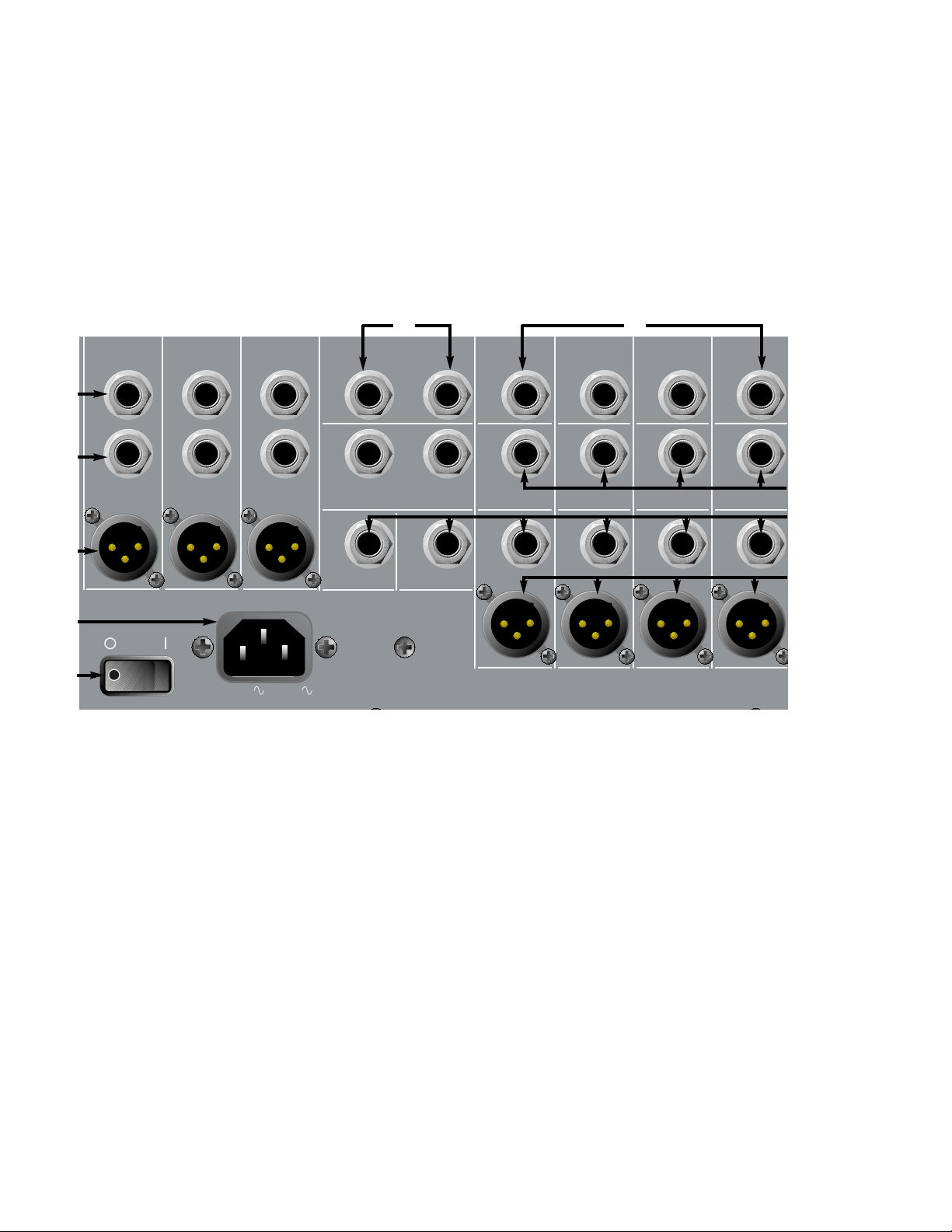
REAR PANEL CONNECTIONS
12
(49) L, R, MONO INSERT
These 1/4" stereo (TRS) jacks, provided on the LEFT, RIGHT and MONO channels, allow an
external device to be inserted into the signal path, pre-MASTER FADER. The tip carries the
signal being sent and the ring is the signal return. A switch in the jack connects the send to
the return if no plug is inserted. The signal must be returned to this jack when this feature is
used. Failure to return the signal will result in no output.
(50) L, R, MONO UNBAL (UNBALANCED OUTPUT)
These 1/4" jacks allow output of an unbalanced signal and are provided for the LEFT, RIGHT
and MONO channels.
(51) L, R, MONO BAL (BALANCED OUTPUT)
These XLR connectors allow output of a balanced signal and are also provided for the LEFT,
RIGHT and MONO channels. The unbalanced and balanced outputs can be used
simultaneously, but both output levels are controlled by the corresponding MASTER FADER.
(52) RETURN INPUTS
These 1/4" balanced (TRS) high-impedance inputs can be used as stereo or individual
returns. Designed for effects return, they can also be used as additional stereo inputs. The
MONO/LEFT input provides signal to both inputs if no connector is attached to the RIGHT
jack. The tip is the positive input for both balanced and unbalanced use.
49
50
51
58
57
52
53
54
55
56
INSERT
(TRS)
LEFT
MONO
INSERT
(TRS)
RIGHT
INSERT
(TRS)
(UNBAL)
(UNBAL) (UNBAL)
MONO
OUT
RIGHT
OUT
LEFT
OUT
(BAL)(BAL)(BAL)
POWER
100VAC -240VAC
50/60 Hz
70 WATTS
RETURN 1
RIGHT
RIGHT
RETURN 2
(UNBAL)
AUX 6
OUT
MONO/
LEFT
MONO/
LEFT
(UNBAL)
AUX 5
OUT
COMP 4
I/O
T=IN
R=OUT
SUB 4
OUT
(UNBAL)
AUX 4
OUT
(BAL)
COMP 3
I/O
T=IN
R=OUT
SUB 3
OUT
(UNBAL)
AUX 3
OUT
(BAL)
COMP 2
T=IN
R=OUT
(UNBAL)
(BAL)
I/O
SUB 2
OUT
AUX 2
OUT
COMP 1
I/O
T=IN
R=OUT
(UNBAL)(UNBAL)(UNBAL)(UNBAL)
(UNBAL)
SUB 1
OUT
(UNBAL)
AUX 1
OUT
(BAL)
Page 13

(53) COMPRESSOR I/O (INPUT/OUTPUT)
These 1/4" stereo (TRS) jacks allow the internal compressors for each SUB group to be
patched to an input channel or to an external device. The tip carries the input (return) signal
to the compressor and the ring carries the output (send).
(54) SUB OUT
These 1/4" (TRS) unbalanced outputs provide signal from the SUB groups.
(55) AUX 1 - 6 OUT (UNBALANCED)
These 1/4" (TS) jacks provide signal from the AUX buses.
(56) AUX 1 - 4 OUT (BALANCED)
These XLR connectors are provided on AUX 1–4 and provide output from those buses.
These can be used simultaneously with the unbalanced jacks (55), but both levels will be
determined by the AUX SEND LEVEL (21).
POWER
(57) REMOVABLE POWER CORD
This receptacle is for the IEC line cord (included) that provides AC power to the unit. Connect
the line cord to this connector and to a properly grounded AC supply. Damage to the
equipment may occur if an improper line voltage is used (see voltage marking on unit). Never
remove or cut the ground pin of the line cord plug. The console is supplied with a properly
rated line cord. If lost or damaged, replace this cord with one of the proper rating.
NOTE: FOR UK ONLY
If the colors of the wires in the mains lead of this unit do not correspond with the colored
markings identifying terminals in your plug, proceed as follows: (1) The wire that is colored
green and yellow must be connected to the terminal marked by the letter E, or by the earth
symbol, or colored green or green and yellow. (2) The wire that is colored blue must be
connected to the terminal that is marked with the letter N, or colored black. (3) The wire
that is colored brown must be connected to the terminal that is marked with the letter L
or colored red.
(58) POWER SWITCH
Place this switch in the “|” position to apply power to the RQ 4300. Return it to the “O”
position to turn the unit off. It is recommended that the unit be turned off while patching
and/or applying power to external equipment to be used in conjunction with the RQ 4300.
The POWER LED (48) will illuminate when power has been applied and the unit is on.
13
Page 14
14
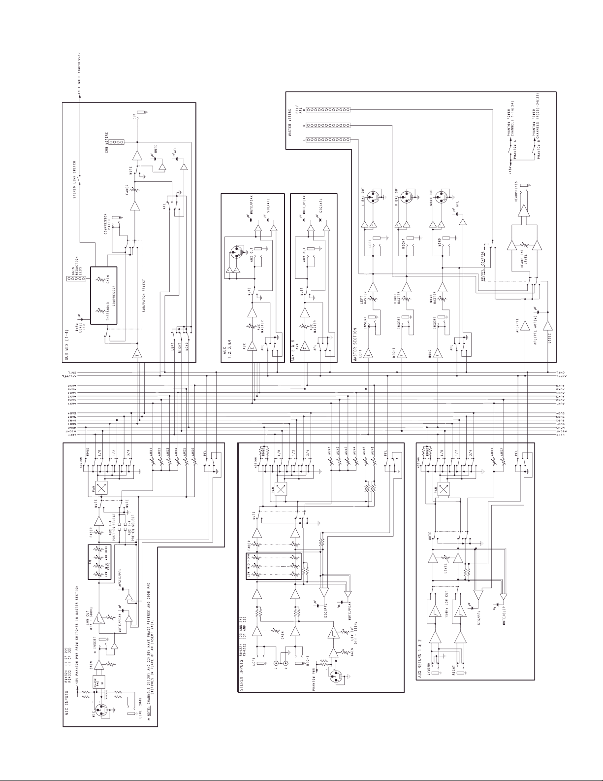
BLOCK DIAGRAM
Page 15
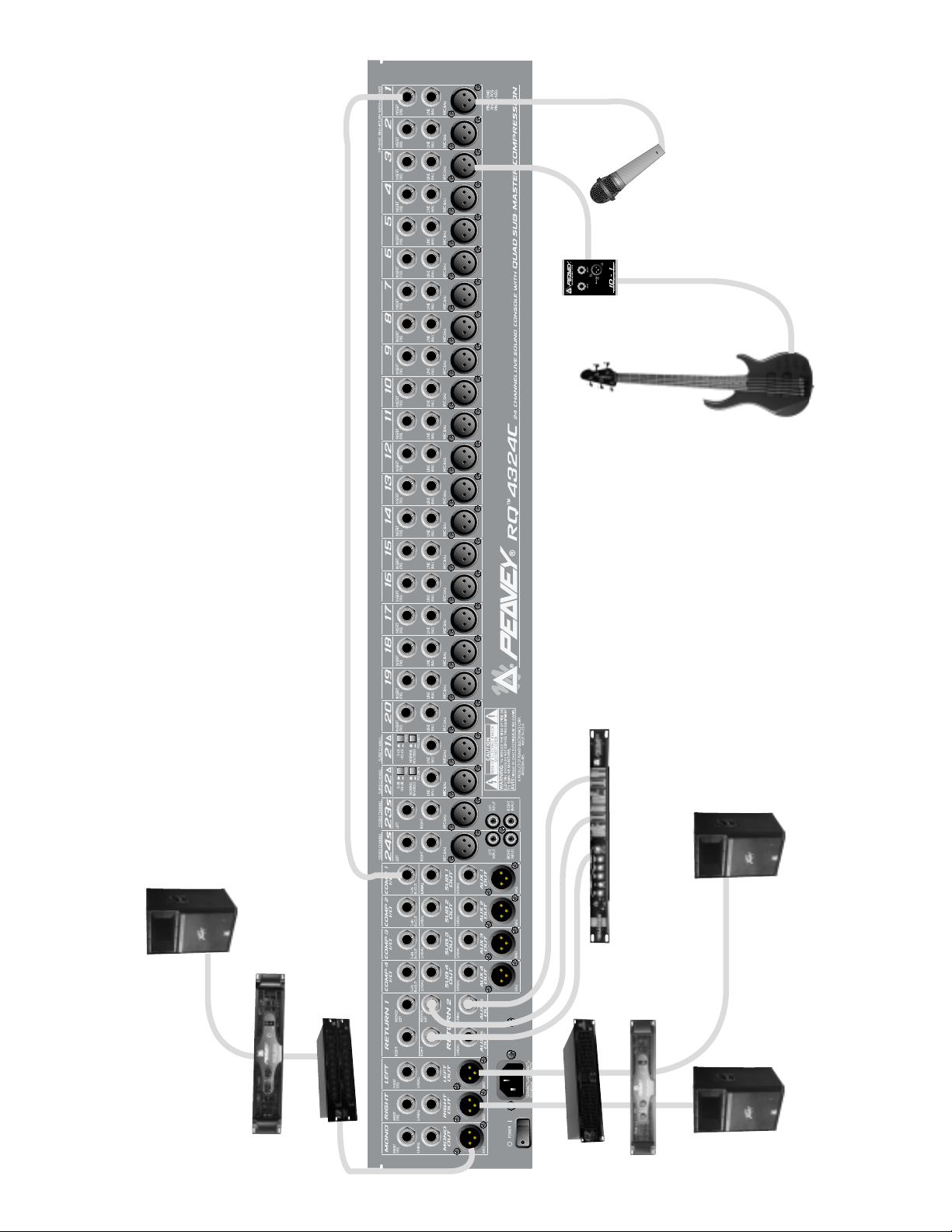
15
Direct Box
Mic
Bass Guitar
Comp 1 patched to Channel 1
Left, Center, Right Configuration
900
®
(bridged)
GPS
2G
™
SP
(center)
231F
™
Q
®
Out In
DeltaFex
1500
®
GPS
215F
™
Q
™
2G
SP
(left)
™
2G
SP
(right)
Page 16
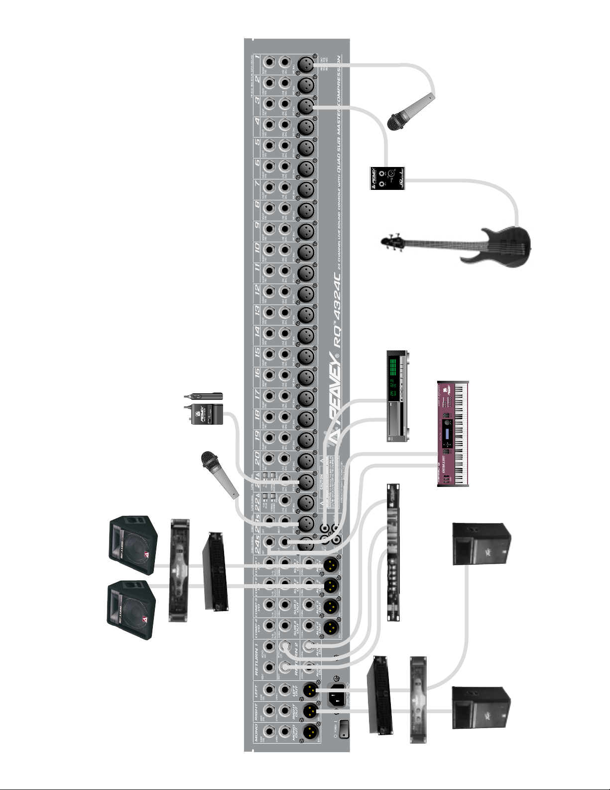
16
Wireless
Mic
Mic
Direct Box
Bass Guitar
CD Player
Stereo Configuration
900
112M
®
SP
112M
®
SP
®
GPS
Mic
215F
™
Q
®
Out In
DeltaFex
1500
®
GPS
215F
™
Q
Keyboard
(stereo)
™
™
2G
SP
2G
SP
Page 17
17
RQ™4324 and 4332 Sound Reinforcement Mixer
Specifications:
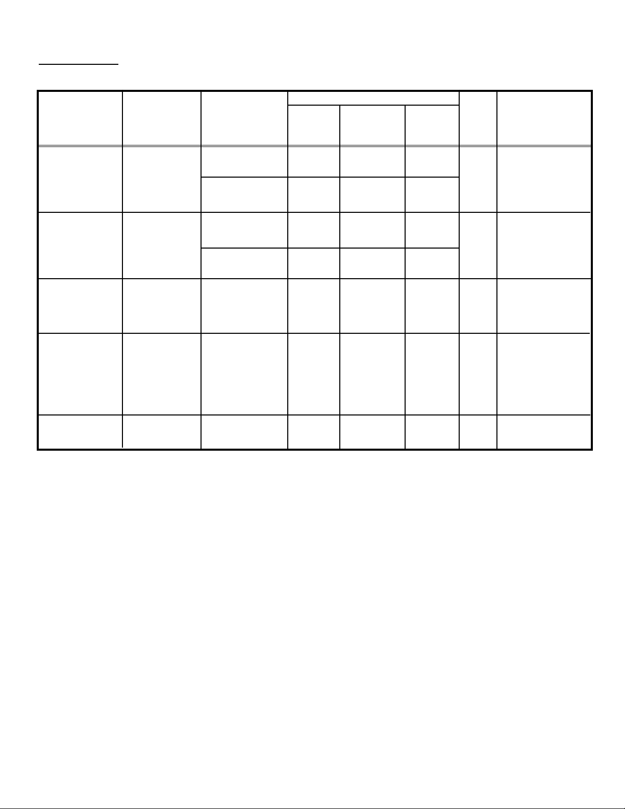
Input Specifications:
Function Input Z Input Input Levels Bal./ Connector
(Ohms) gain Min.** Nominal Max. Unbal.
Min. setting
Microphone 2 k Max. Gain -74 dBu -54 dBu -38 dBu Bal. XLR Pin:
(150 Ohms) (58 dB) Pin 1 (Ground)
Pin 2 (+),
Min. Gain -24 dBu -6 dBu +12 dBu Pin 3 (-)
(10 dB)
Line Input 10 k Max. Gain -54 dBu -34 dBu -18 dBu Bal. 1/4" TRS:
(10 k Ohms) (38 dB) Tip (+),
Ring (-),
Min Gain -6 dBu +14 dBu +32 dBu Sleeve (Ground)
(-10 dB)
Insert 22 k N/A -16 dBu +4 dBu +22 dBu Unbal. 1/4" TRS:
Return (0 dB) Tip Send,
Ring Return
Sleeve Ground
Stereo 20 k Max. Gain -29 dBu -9 dBu +4 dBu Unbal. 1/4" Phono
Line Input (20 dB)
Sleeve (Ground)
(RCA’s) Min. Gain -16 dBu +4 dBu +18 dBu
0 dB
(detent)
Aux Return 22 k N/A -24 dBu +4 dBu +22 dBu Unbal. 1/4" Phono
(0 dB)
0 dBu = 0.775 V (RMS)
** Minimum input level (Sensitivity) is the smallest signal that will produce nominal output (+4 dBu) with sub and
master controls set for maximum gain.
* Nominal settings are defined as all controls set at 0 dB (or 50% rotation for rotary pots) except the gain
adjustment pot, which is as specified.
Page 18

18
* 0 dBu = 0.775 V (RMS)
Output Specifications:
Function Minimum Output Levels, Bal./ Connector
Load Z Nominal Max. Unbal.
(Ohms)
Main L/R 600 +4 dBu +22 dBu Unbal. 1/4" Phono (Unbal);
Bal. XLR: Pin 1 Ground
Pin 2 (+)
Pin 3 (-) (Bal.)
Mono 600 +4 dBu +22 dBu Unbal. 1/4" Phono (Unbal.);
Bal. XLR: Pin 1 Ground
Pin 2 (+)
Pin 3 (-)
Sub Master 600 +4 dBu +22 dBu Unbal. 1/4" Phono
Aux Send 600 +4 dBu +22 dBu Unbal. 1/4" Phono (Unbal.);
XLR Pin 1 Ground
Pin 2 (+)
Pin 3 (-)
Channel 600 +4 dBu +22 dBu Unbal. 1/4" TRS: Tip Send,
Insert Send Ring Return,
Sleeve Ground
Headphone 8 +4 dBu +22 dBu Unbal. 1/4" TRS: Tip Left
(no load) Ring Right
Sleeve Ground
Gain:
Mic Input Gain Adj Range: 10 dB to 58 dB
Mic Input to Sub Output 78 dB (Max Gain)
Mic lnput Longest Path 88 dB (Max Gain)
Line Input Gain Adj Range: -10 dB to 38 dB
Line Input to Sub Output 58 dB (Max Gain)
Line Input Longest Path 68 dB (Max Gain)
Stereo Line Input Gain Adj Range -60 dB to 10 dB
Stereo Line Input to Sub Output 30 dB (Max Gain)
Stereo Line Input Longest Path 40 dB (Max Gain)
Aux Return to Sub Output 28 dB (Max Gain)
Aux Return Longest Path 38 dB (Max Gain)
Frequency Response:
Mic Input to L-R Output 20 Hz to 50 kHz +0 dB / -1 dB
Stereo Input to L-R Output 20 Hz to 30 kHz +0 dB / -1 dB
Total Harmonic Distortion (THD):
< 0.007% 20 Hz to 20 kHz Mic to L-R output at Nominal Level (20 Hz - 80 kHz BW)
Page 19

19
Hum and Noise:
Output Residual Noise S/N Ratio Test Conditions
Ref: 0 dBu
Master L/R -105 dBu 109 dB All Faders Down
Mono
-90 dBu 94 dB Master Fader Nominal,
Channel Faders Down,
All Channels Assigned
Submaster -98 dBu 102 dB All Faders Down
-88 dBu 92 dB Submaster Fader
Nominal, Channel
Faders Down,
All Channels Assigned
(Hum and Noise Measurements: 22 Hz to 22 KHz BW)
Equivalent Input Noise (EIN):
-128 dBu (Input terminated with 150 Ohms)
Crosstalk:
>90 dB Adjacent Input Channels (20 Hz - 20 kHz)
>70 dB Left to Right Outputs (20 Hz - 20 kHz)
Common Mode Rejection Ratio (Mic Input):
50 dB min (20 Hz - 20 kHz)
70 dB typ @ 1 kHz
Meters:
L/R Master and all Submasters = 12 segment, peak reading
(0 dB= +4 dBu)
Signal / Overload Indicators:
Red LED lights 2 dB below clipping
Lamp Power:
12 VDC @ 350mA per connector, or 12VDC @ 700mA total maximum load
Power Requirements:
DOM: 100 VAC –240 VAC 50/60 Hz 70 Watts Nominal, 24 chan
80 Watts Nominal, 32 chan
RQ™4324
Height: 8.9" (226 mm)
Width: 36.6" (930 mm)
Depth: 19.5" (495 mm)
Weight: 36 lbs. (16.4 kg)
RQ™4332
Height: 8.9" (226 mm)
Width: 44.6" (1132 mm)
Depth: 19.5" (495 mm)
Weight: 48 lbs. (21.8 kg)
Dimensions:
Page 20

20
Serie RQ™4300
Consola de grabación y sonorización con calidad de referencia
INTODUCCIÓN
Gracias por su compra de la consola de mezcla de la serie RQ
™
4300. La RQ™4300 representa
años de experiencia en diseño de mezcladoras, y ofrece increíble versatilidad en sus flexibles 13
buses. Sus impresionantes 4 sub grupos, 6 Auxs, salidas L/R (izquierda y derecha) y mono ponen a
la RQ™4300 en su propia liga. Y si eso no fuera suficiente, cada bus incluye un compresor
dinámico de alta calidad que puede ser usado en su submezcla correspondiente, o conectado a
cualquier punto de inserción. Su diseño compacto es ideal tanto para sonido en vivo como para
instalaciones permanentes. Este manual cubrirá las características y controles de ambas RQ
™
4324
y RQ
™
4332.
• 24 (RQ 4324) ó 32 (RQ 4332) canales de entrada con ganancia, ecualizador y controles de
asignación de Paneo, Aux, Sub, L/R y mono
• Preamplificadores de micrófono (XLR) de muy bajo ruido en todos los canales de entrada
• Entradas balanceadas de 1/4" en los CANALES 1-22 (RQ 4324) ó 1-30 (RQ 4332)
• Puntos de inserción en los canales 1-20 (RQ 4324) ó 1-28 (RQ 4332)
• Diseño innovador de chasis con conexiones retraídas en el panel trasero (ideal para
posicionamiento sobre un escritorio)
• Fader suave de 60mm en cada canal, Subs 1-4, salidas L/R y mono
• Poder phantom con interruptores de cancelación separados para seleccionar ya sea canales
1-16 ó 17-24 (RQ 4324); 1-24 ó 25-32 (RQ 4332)
• Dos SUPER CANALES con pad (-20 dB) e interruptor de POLARIDAD
• Dos CANALES ESTÉREO con conectadores de 1/4" y RCA
• 6 envíos AUX (4 XLR balanceados)
• 4 SUB grupos con compresores dinámicos parchables.
• Interruptores de fase y pad en Super Canales
• Interruptor de mute y PFL, LEDs de saturación (PK) y señal (SIG) en todos los canales de
entrada.
• Dos Retornos con posibilidad de filtros de recorte de graves (150 Hz), control de nivel,
asignación de bus, mute y AFL.
• PFL (nivel de entrada pre fader) en todos los canales de entrada
• AFL (nivel de entrada post fader) en Envíos de Aux, Retornos de Aux, Sub y canales mono
• Salida de auriculares estéreo
• Salida mono balanceada (XLR) y no balanceada (1/4") para MONO, LEFT y RIGHT
• Puntos de inserción maestros (1/4") L/R y MONO
• LEDs de saturación de subgrupo y maestro en suma de amplificadores y Post-fader.
EXPLICACIÓN DE LOS TÉRMINOS
BUSES – Las diferentes rutas a través de la consola desde los canales a las varias salidas. La
mezcladora RQ 4300 contiene 13 buses diferentes: L, R, MONO, SUBS 1-4, AUX 1-6.
SUB grupos – Los buses usados para agrupar canales. Esto permite controlar una submezcla de
muchos canales por medio de un solo fader.
ESPAÑOL
Page 21

21
ENVÍOS AUX – Los buses usados para mandar señales a efectos y monitores desde cada canal.
PRE significa que el nivel del AUX no se verá afectado por la posición del fader. POST indica que el
nivel del AUX será afectado por el fader.
PFL – ESCUCHA PREVIA AL FADER (Por sus siglas en Inglés). El PFL manda la señal a la salida
de auriculares y no es afectada por la posición del fader.
AFL – ESCUCHA DESPUÉS DEL FADER (Por sus siglas en Inglés). El AFL manda la señal a la
salida de auriculares y no es afectada por la posición del fader.
CORTE DE GRAVES – (Corte de graves del canal) Este ajusta las frecuencias en el canal dónde
las frecuencias graves comenzarán a desvanecerse. Se puede ajustar desde OFF (inaudible) a
300 Hz.
1/2 , 3/4, L/R, MONO – estos interruptores mandan la señal a sus respectivos buses de salida.
BAL/PAN determinan entre 1/2, 3/4, y L/R.
PUNTOS DE INSERCIÓN – Estos conectadores permiten que la señal sea enviada de un canal y
regresada a este, permitiendo insertar equipo periférico a la ruta de la señal.
MID FREQ – Este control selecciona la frecuencia ajustable por el control de medios del
ecualizador.
COMPRESORES – Estos reducen la razón de los niveles 4 a 1 cundo se alcanza el umbral.
UMBRAL – Este control determina el nivel al cual el compresor se activa
GANANCIA – Este control ajusta el nivel de salida del compresor. Puede ser considerada
una ganancia ajustadora, ya que permite recuperar la diferencia perdida por la compresión.
LINK – Cuando este botón es oprimido, la entrada del compresor 1 activará los compresores
1 y 2, y la entrada 3 activará los compresores 3 y 4.
SUB GRUPO/EXTERNO – Este botón manda la señal del compresor a la salida del
compresor (el LED lo indicará). Este conectador está cableado al revés que un conectador
de inserción, permitiendo que el compresor sea parcheado por medio de un cable de 1/4".
PODER PHANTOM – Provee +48 Voltios de poder a los micrófonos que lo necesitan.
CABLEADO DE CONECTADORES
A menos que se indique de otra forma, todas las entradas y salidas están cableadas de la siguiente
manera:
XLR (MIC) - Pin 1 = TIERRA
Pin 2 = POSITIVO
Pin 3 = NEGATIVO
TS y TRS Punta = POSITIVO
Anillo = NEGATIVO (RETORNO)
Manga = TIERRA
RCA (Phono) Punta = POSITIVO
Manga = TIERRA
Page 22

DESEMPAQUE
Inspeccione la consola cuidadosamente durante el desempaque. Si encuentra cualquier daño
notifique a su distribuidor inmediatamente. Asegúrese de guardar la caja y todos los materiales de
empaque. Si alguna vez necesita mandar la unidad de regreso a Peavey Electronics, alguno de sus
centros de servicios, o distribuidor, use solamente los materiales de empaque originales.
CANALES ESTÁNDAR
CONEXIONES DE LA PARTE TRASERA
(1) PUNTO DE INSERCIÓN
Este conectador de 1/4" TRS (punta, anillo, manga,
por sus siglas en Inglés) permite sacar y regresar
una señal prefader, pre eq del canal. Los puntos de
inserción son comúnmente usados para mandar una
señal a un procesador externo. Los compresores
incluidos en la RQ 4300 pueden ser parcheados a
cualquier canal por medio del PUNTO DE
INSERCIÓN.
(2) LÍNEA
Este conectador de 1/4" balanceado (TRS) de alta
impedancia es una entrada para señales de alto
nivel. La punta es la entrada positiva, que también
debe ser usada para entradas no balanceadas. La
entrada es conectada a través de un pad de 20 dB a
la entrada de MICRO (3). Las dos entradas no
pueden ser usadas simultáneamente.
(3) MICRO
Este conectador balanceado XLR de 3 vías de baja
impedancia ha sido intencionado para micrófonos. Otras fuentes de baja impedancia como
instrumentos mandados a la consola por medio de cajas directas usarán esta entrada también.
CONTROLES DE LOS CANALES
(4) GANANCIA
El control de Ganancia varía la ganancia de entrada del canal para permitir un rango
dinámico más amplio. El rango de ajuste de la Ganancia es +10 dB a +58 dB para la entrada
XLR y –10 dB a +38 dB para la entrada de línea. El ajuste adecuado de la ganancia de
entrada incrementará la razón señal/ruido. Puede ser ajustado presionando el interruptor de
PFL (15) y ajustando el control de ganancia hasta que se identifique el nivel 0 en el medidor
LED de AFL/PFL (45).
(5) RECORTE DE GRAVES
Este control ajusta el filtro de recorte de graves. Varía de ningún recorte a 300 Hz. Este
control reduce o elimina frecuencias extremadamente graves que causan elementos
indeseables en la mezcla, además de ser una buena herramienta para alterar tonos. También
puede ser usado para eliminar las frecuencias demasiado graves de algunas voces
masculinas.
22
T
3
2
1
IP=SEND RING=RETURN SLEEVE=GROUND)
INSERT
(TRS)
12
INSERT
(TRS)
LINE
(BAL)
LINE
(BAL)
MIC
(BAL)
MIC
(BAL)
Page 23

(6) EQ AGUDO
El EQ agudo es activo, de tipo shelving, con control de tono activo que
varía el rango de frecuencias por encima de los 12 kHz por +/- 15 dB.
(7) EQ DE MEDIOS (dB)
Este es un control de tono activo tipo bandpass (corta o incrementa) que
varía los niveles de frecuencias medias +/- 15 dB dentro del rango de
200 Hz a 6 kHz.
(8) EQ DE MEDIOS (Hz)
Este control determina la frecuencia central del EQ DE MEDIOS que
varía entre 200 Hz y 6 kHz.
(9) EQ GRAVE
El EQ grave es de tipo shelving con control de tono activo que varía el
nivel de frecuencias por +/- 15 dB (la frecuencia de esquina es 75 Hz).
(10) AUX 1-4
Estos controles ajustan el nivel de la señal de un canal (pre fader) que
se enviará a la mezcla auxiliar. La ganancia varia desde menos infinito
(– ∞) hasta +10 dB. La ganancia unitaria es el centro marcado. Los
auxiliares prefader son comúnmente usados para mandar señal a
monitores de escenario, pero también pueden ser usados para generar
mezclas independientes.
NOTA: Los ENVIOS AUX 1-4 han sido diseñados para mandar seña pre
eq, pero pueden ser modificados (internamente) para que generen
señales post eq. Contacte al Departamento de Servicio de Peavey
Electronics para más información. Los ENVIOS AUX 5-6 siempre son
post eq. La ganancia varía desde menos infinito (– ∞) hasta +10 dB. La
ganancia unitaria es el centro marcado.
(11) AUX 5-6
Estos controles ajustan el nivel de señal post fader que se envía a la
mezcla auxiliar. La ganancia varía desde menos infinito (– ∞) hasta
+10 dB. La ganancia unitaria es el centro marcado.
(12) PAN
Este control determina la posición de la señal con respecto a las salidas
L/R y SUB 1-4. El rotar este control en contra de las manecillas del reloj
incrementa la cantidad de la señal enviada al lado izquierdo (L) o subs
nones. La rotación en dirección de las manecillas del reloj incrementa la
cantidad de la señal enviada al lado derecho o SUBS pares. Por
ejemplo, con el interruptor de asignación (13) en 1/2 posición, rotar el
control en contra de las manecillas del reloj incrementa la cantidad de
señal mandada al SUB 1, mientras que rotarla en la dirección contraria la
mandará al SUB 2. La posición central mandará la misma cantidad a las
dos.
23
5
4
5
6
7
8
9
12
16
10
11
13
14
15
64
37
2
9
1
010
10050
150
20
300
OFF
0
33
66
9
12
12
1515
0
33
66
9
12
12
1515
1K700
EQUALIZATION
2.5K
300
6K
200
0
33
66
9
12
12
1515
0
3
3
6
15
40
10
0
3
3
6
15
40
10
0
3
3
6
PREPOST
15
40
10
0
3
3
6
15
40
10
0
3
3
6
15
40
10
0
3
3
6
15
40
10
C
L
R
1/2 3/4
1
dB
dB
dB
dB
dB
dB
8
9
9
9
5
5
5
5
5
5
GAIN
LOW
CUT
(Hz)
(dB)
MID
(dB)
MID
FREQ.
(Hz)
LOW
(dB)
AUX
AUX
AUX
AUX
AUX
AUX
PAN
HI
1
2
3
4
5
6
L/R MONO
CHANNEL
1
MUTE/
PK
10
6
3
0
6
12
20
30
SIG/
PFL
Page 24

(13) ASIGNACIÓN 1/2, 3/4, L/R, MONO
Estos interruptores post fader, post eq determinan a dónde se manda la señal de cada canal.
Por ejemplo, para mandar una señal a los SUBS 1 y 2, oprima el botón 1/2. El control de
PAN (12) determina cuánta señal será enviada a cada SUB grupo.
(14) INTERRUPTOR DE MUTE
Este interruptor mutea los envíos AUX, SUB, L/R y MONO del canal correspondiente. Ente
interruptor está equipado con un LED rojo que se ilumina cuando el canal es muteado.
Cuando el interruptor de MUTE no esté activado, el LED funciona como indicador de
saturación (PK) que se iluminará 2 dB antes de saturar. Mutear el canal no previene que la
señal del PFL siga siendo enviada a la mezcla PFL cuando el interruptor PFL (15) está
activado.
(15) INTERRUPTOR DE PFL/LED DE SEÑAL PFL
Este interruptor conecta la señal pre fader a la mezcla PFL. Cuando este está activado, la
señal del canal puede ser monitoreada por medio de auriculares y/o luces AFL/PFL. Un LED
amarillo en la sección MAESTRA MONO (45) se encenderá de forma intermitente indicando
que la señal de salida de auriculares es PFL. Seleccionar PFL permite al operador
monitorear el canal aun cuando este ha sido muteado, y es especialmente útil para medir
CDs y cintas. Cuando el interruptor PFL está en la posición salida, el LED amarillo se
encenderá de manera intermitente indicando la presencia de señal (-20 dBu)
(16) FADER DE CANAL
Este control varía el nivel de señal enviada del canal a los subs L/R, SUB, y/o MONO de
(– ∞) a +10 dB. La posición 0 es ganancia unitaria, o sea ningún incremento ni recorte en
nivel por medio del control de GANANCIA (4), y es la posición óptima para este control. Si el
nivel es demasiado silencioso o demasiado elevado en ganancia unitaria del fader, se puede
usar el control de GANANCIA (4) del canal para ajustarlo.
SUPER CANALES
[CANALES 21-22 (RQ 4324) Y 29-30 (RQ 4332)]
Las conexiones de entrada y controles del canal de los
SUPER CANALES son iguales a los CANALES
ESTÁNDAR con la excepción de los PUNTOS DE
INSERCIÓN. En lugar de PUNTOS DE INSERCIÓN, los
SUPER CANALES cuentan con:
(17) PAD
Este interruptor atenúa (reduce) la señal de entrada por
20 dB. Esto permite acomodar señales de niveles más
elevados sin saturar y es especialmente útil cuando se
microfonean fuentes de alto nivel (SPL) como son baterías
o amplificadores de guitarra. También es recomendable
para señales “calientes” de línea como teclados o algunos
micrófonos inalámbricos.
(18) POLARIDAD
Este interruptor invierte la polaridad tanto de una entrada XLR como LÍNEA para compensar
alguna señal fuera de fase que de otra manera tendría como resultado cancelaciones en la
mezcla.
24
17
18
22
0 dB
-20 dB
NORMAL
REVERSED
LINE
(BAL)
MIC
MIC
(BAL)
PAD
POLARITY
21
0 dB
-20 dB
NORMAL
REVERSED
LINE
(BAL)
MIC
(BAL)
PAD
POLARITY
Page 25

CANALES ESTÉREO
[CANALES 23-24 (RQ 4324) Y 31-32 (RQ4332)]
Los CANALES ESTÉREO ofrecen los mismos controles que los CANALES ESTÁNDAR con la
excepción del control de frecuencias medias (8). La banda central está ajustada a 850 Hz. En lugar
del control de frecuencias medias, los CANALES ESTÉREO ofrecen controles de ganancia
independientes para micro (XLR) y línea.
(19) ENTRADAS DE LÍNEA DE 1/4" ESTÉREO
Estas entradas de TS son entradas no balanceadas de nivel de línea para señales estéreo
(L/R). Están conectadas en paralelo con las ENTRADAS DE LÍNEA ESTÉREO RCA (20). Si
hay una fuente MONO de línea, use un cable “Y” o alguno de los canales con entradas de
línea MONO.
(20) ENTRADAS DE LÍNEA ESTÉREO RCA
Estas entradas de RCA son entradas no balanceadas de nivel de línea para señales estéreo
(L/R). Están conectadas en paralelo con las ENTRADAS DE LÍNEA DE 1/4" ESTÉREO (19).
25
19
20
24s
LEFT
RIGHT
MIC
(BAL)
LEFT
INPUT
RIGHT
INPUT
23s
LEFT
RIGHT
MIC
(BAL)
LEFT
INPUT
RIGHT
INPUT
Page 26

CARACTERÍSTICAS Y CONTROLES DE LA SECCIÓN MAESTRA
ENVÍOS AUXILIARES
(21) NIVEL
Este control ajusta el nivel de salida de las varias mezclas auxiliares y es ajustable desde
cero entrada (– ∞) a +10 dB.
26
21
22
23
24
25
26
27
28
31
33
32
29
30
34
37
39
42
43
38
40
35
41
36
44
47
45
48
46
SECCIÓN MAESTRA
LEVEL
LEVEL
EXTERNAL
6
12
GAIN
THRESHOLD
-5
CLIP
+6
0
-20
GAIN
(dB)
8
10
1
3
6
9
12
(dB)
LEFT
RIGHT
MONO
MUTE
SEND 3
15
SEND 6
15
AUX
3
6
40
MUTE/
PEAK
SIG/
AFL
AUX
3
6
40
MUTE/
PEAK
SIG/
AFL
COMPRESSOR I/O
SUBGROUP
4
2
LINK 3/4
-15 +5
-25 +15
-30 OFF
0 dBu (INPUT)
SUB 4
4
AUX
SEND 1
LEVEL
0
3
3
6
5
15
40
10
dB
MUTE/
PEAK
SIG/
AFL
AUX
SEND 4
0
LEVEL
3
3
6
5
15
40
10
dB
MUTE/
PEAK
SIG/
AFL
COMP 1 COMP 2 COMP 3 COMP 4
COMPRESSOR I/O
SUBGROUP
EXTERNAL
6
GAIN
(dB)
4
8
10
2
12
0
1
3
6
9
12
GAIN
REDUCTION
THRESHOLD
(dB)
-5
-15 +5
-25 +15
-30 OFF
0 dBu (INPUT)
SUB 1
CLIP
LEFT
+6
0
RIGHT
-20
MONO
1
MUTE
SEND 2
6
15
40
MUTE/
PEAK
SEND 5
6
15
40
MUTE/
PEAK
COMPRESSOR I/O
SUBGROUP
EXTERNAL
6
4
8
10
2
12
0
LINK 1/2
1
3
6
9
12
GAIN
REDUCTION
THRESHOLD
(dB)
-5
-15 +5
-25 +15
-30 OFF
0 dBu (INPUT)
SUB 2
CLIP
+6
0
RIGHT
-20
MONO
2
MUTE
AUX
3
SIG/
AFL
AUX
3
SIG/
AFL
GAIN
(dB)
LEFT
0
0
3
5
10
dB
3
5
10
dB
COMPRESSOR I/O
SUBGROUP
4
2
0
REDUCTION
-15 +5
-25 +15
-30 OFF
0 dBu (INPUT)
SUB 3
3
0
3
5
10
dB
0
3
5
10
dB
EXTERNAL
6
12
0
GAIN
REDUCTION
THRESHOLD
-5
CLIP
+6
0
-20
LEVEL
LEVEL
8
10
1
3
6
9
12
(dB)
RIGHT
MONO
MUTE
GAIN
(dB)
LEFT
RETURN
3
6
15
40
3
6
15
40
1/2 3/4
L/R
AUXILIARY MASTER
L
3
6
15
40
MUTE/
PEAK
SIG/
AFL
DYNAMICS
CLIP
DYNAMICS
RETURN
1
LOW CUT LOW CUT
(150 Hz) (150 Hz)
0
3
5
10
dB
0
3
5
10
dB
MONO
C
R
0
3
5
10
dB
AUX
AUX
BAL/
PAN
LEVEL
1
2
2
0
3
6
15
40
0
3
6
15
40
1/2 3/4
L/R MONO
C
L
0
3
6
15
40
MUTE/
PEAK
SIG/
AFL
DESIGNED IN U.S.A.
3
5
10
dB
3
5
10
dB
R
LEVEL
3
5
10
dB
LR
9
6
3
0
3
6
9
15
21
27
33
CLIP
9
6
3
0
3
6
9
15
21
27
33
MASTER
LR
AUX
1
AUX
PHANTOM
2
HEADPHONE
BAL/
PAN
MONO
MONO
POWER
POWER
(+48V)
1-16
17-24
HEADPHONE LEVEL
5
64
37
2
1
010
AFL/PFL ACTIVE
CLIP
9
6
3
0
3
6
9
15
21
27
33
TM
8
9
CLIP
9
6
3
0
3
6
9
15
21
27
33
10
6
3
0
6
12
20
30
10
AFL
6
3
0
6
12
20
30
10
AFL
6
3
0
6
12
20
30
10
AFL
AFL
6
3
0
6
12
20
30
10
6
3
0
6
12
20
30
10
6
3
0
6
12
20
30
10
10
6
3
0
6
12
20
30
AFL
6
3
0
6
12
20
30
Page 27

(22) LED DE MUTE/SATURACIÓN
Este interruptor mutea la señal de salida de su respectivo ENVIO AUX. La iluminación del
LED correspondiente significa este estatus. Cuando el interruptor de mute es apagado, el
LED funciona como indicador de saturación (PK) que se iluminará a 2 dB antes de la
saturación.
(23) LED DE AFL
Este interruptor manda la señal post fader (AFL) a la salida de auriculares (39), y activa el
LED AFL/PFL. Un LED adyacente se ilumina para indicar la selección. Si AFL no está
seleccionado, el LED se iluminará intermitentemente para indicar la presencia de señal (-20
dB). Seleccionar AFL permite monitorear ENVIOS AUX con el indicador AFL/PFL completo
(45), así como permitir al operador escuchar la salida.
COMPRESORES
Los compresores de la serie RQ funcionan de manera similar a controles de volumen automáticos.
En otras palabras, ajustan las señales a un rango dinámico manejable. Por ejemplo, supongamos
que un cantante canta demasiado suave y se pierde en la mezcla en ciertas partes de la canción,
pero canta muy fuerte en otras. Para controlar este problema, el operador tiene que ir cambiando el
nivel constantemente en tiempo real. El usar un compresor elimina este problema. Los compresores
de la RQ han sido preajustados a una razón de 4:1; por cada 4 dB de cambio en la señal de
entrada, el cambio de salida sólo será de 1 dB. La compresión entra en acción una vez que el nivel
determinado por el UMBRAL (28) ha sido alcanzado. Un ajuste alto, en dirección de las manecillas
del reloj, resultará compresión de notas más fuertes. Un ajuste bajo, en contra de las manecillas,
comprimirá un rango más amplio de notas.
(24) I/O DEL COMPRESOR
Este interruptor determina si el compresor será usado en la mezcla SUB o si será parcheado
a otro canal o destino externo. El LED amarillo correspondiente se iluminará cuando el
compresor sea parcheado externamente. Este interruptor también puede ser usado para
llevar a cabo la función de “bypass”. Cuando el compresor es asignado al grupo SUB, el
conectador I/O permite al operador escuchar la diferencia entre las señales comprimida y no
comprimida cuando el compresor es usado en el grupo SUB.
(25) GANACIA
Este control ajusta el nivel de salida del compresor y permite la recuperación de ganancia
perdida por la compresión. La cantidad de ganancia perdida será representada en el LED DE
REDUCCIÓN DE GANANCIA (27), y un ajuste similar en el control de GANANCIA se
aproximará a niveles precomprimidos.
(26) LINK
Este interruptor permite que el compresor de sub grupo 1 (ó 3) sea ligado con el compresor
del sub grupo 2 (ó 4). Esto funciona si los dos sub grupos se usan para crear una imagen
estéreo. Cuando están ligados, los detectores de voltajes RMS se suman para una
presentación real de los dos niveles. Cuando está activado el LINK, los controles en el
primero de los dos grupos afectará a los dos canales. Los controles del segundo compresor
son desactivados. El medidor de reducción de ganancia del primer grupo es correcto para los
dos grupos y debe ser usado para monitorear la actividad del compresor. Con el LINK
activado el LED amarillo se iluminará.
27
Page 28

NOTA: Cuando ligados, el medidor de reducción de ganancia en el segundo grupo puede
mostrar reducción de ganancia aunque esta no sea un representación verdadera de la
actividad del compresor.
(27) LEDs DE REDUCCIÓN DE GANANCIA
Estos LEDs muestran de manera gráfica la cantidad de ganancia reducida por el compresor
(-1 a -12 dB).
(28) UMBRAL
Este control ajusta el nivel en el que el compresor se activará y es variable de – 30 dBu a
nada de compresión en la posición OFF. El LED adyacente (0 dBu) se iluminará cuando
exista suficiente señal para que el compresor funcione correctamente.
SUB GRUPOS
(29) LED DE NIVEL
Esta muestra representa la cantidad de señal presente en la mezcla de SUB grupo. La señal
es capturada en el amplificador de suma y es post faders maestros para monitorear
saturación en el sub grupo. El indicador de CLIP (saturación) se iluminará cuando la señal se
encuentre 2 dB antes de saturar. Por ejemplo, el SUB fader (33) pude encontrarse en un
nivel aceptable, pero las señales asignadas l SUB pueden estar cerca de la saturación. Si
esto está sucediendo, los ajustes del FADER (16) del canal y la GANACIA (4) pueden
requerir ser evaluados y corregidos.
NOTA: El LED de saturación (CLIP) puede iluminarse antes que cualquier otra indicando que
el amplificador de suma esta saturando.
(30) IZQUIERDO, DERECHO Y MONO (ASIGNACIÓN DE SALIDA)
Estos interruptores determinan hacia donde es mandada la señal de la SUB mezcla. Por
ejemplo, si cada micro de la batería es asignado al SUB 1, oprimir el botón izquierdo (LEFT)
mandará la señal de la SUB mezcla a la salida marcada LEFT OUT en la parte trasera.
(31) MUTE/ LED DE MUTE
Este interruptor mutea todas las salidas del SUB grupo correspondiente. La iluminación de
LED rojo adyacente ocurre cuando el botón de MUTE es oprimido.
(32) LED AFL/AFL
Este interruptor manda la señal post fader de su respectivo SUB grupo a la salida de
AURICULARES (42) y es mostrada en el medidor de NIVEL AFL/PFL (45).
(33) SUB FADER
Este control determina cuanta cantidad de señal es presente en la salida seleccionada.
Como con los faders de los canales, el ajuste óptimo es ganancia unitaria (0). Si el nivel de
salida es demasiado silencioso o demasiado fuerte a ganancia unitaria, los ajustes de
GANACIA y FADER en los canales asignados a esa SUB mezcla deben ser verificados. Si
dos SUB mezclas, digamos SUB 1 y SUB 2 por ejemplo, están intencionadas para ser
estéreo, es necesario ajustar los dos FADERS igualmente y simultáneamente para mantener
el balance.
28
Page 29

(34) CORTE DE GRAVES
Este interruptor activa el filtro de graves (150 Hz -18 dB/por octava). Con este filtro activado,
las frecuencias por debajo de los 150 Hz serán rechazadas. Especialmente cuando se use
reverb, el filtro de graves es benéfico para reducir ruidos graves y ‘lodosos’.
(35) AUX 1 & AUX 2
Estos controles determinan el nivel de señal que regresará al respectivo bus AUX,
permitiendo a músicos o cantantes escuchar efectos externos.
NOTA: No se usen los ENVIOS AUX 1 ó 2 como el camino a equipos periféricos que no
regresarán a las mezclas correspondientes AUX (1 ó 2) dado que puede resultar en un
circuito vicioso.
(36) 1/2, 3/4, L/R, MONO (ASIGNACIONES)
Como los interruptores de asignación de canal, estos botones determinan la asignación de
bus de la señal de entrada. Determinan a dónde se mandará la señal de retorno.
(37) BAL/PAN
Este control determina la localización de la señal en su bus asignado. Rotar el control contra
las manecillas del reloj manda más señal al lado IZQUIERDO y subs no pares; rotar en
sentido de las mancillas mandará más señal al lado DERECHO y subs pares. La posición
central (C) manda la misma cantidad a los dos lados.
(38) NIVEL
Este control determina el nivel de la señal que será enviada a su bus(es) asignado(s).
Funciona de manera similar a los FADERS DE CANALES (16).
(39) LED DE MUTE/SATURACIÓN
Como otros mutes en la consola, este control interrumpe la señal que es enviada a los
bus(es). Iluminación roja del LED indica activación. Cuando el MUTE no está seleccionado,
el LED funciona como indicador de saturación (PK) y se ilumina 2 dB antes de saturar.
(40) INTERRUPTOR AFL/LED DE AFL
Este interruptor manda la señal post fader (AFL) a la salida de AURICULARES (42) y a la
MUESTRA DE NIVEL MONO – AFL/PFL (45). Un LED adjacente se ilumina para indicar está
selección. Si AFL no es seleccionado, el LED se encenderá intermitentemente indicando
presencia de señal (-20 dBu).
(41) PODER PHANTOM
Este interruptor aplica poder (+ 48 CD) a las entradas de micrófono (6) en los canales 1-16 y
17-24 respectivamente (1-24 y 25-32 en la RQ 4332). Esto permite aplicar corriente a los
micros que requieren una fuente de poder externa. Estos interruptores requieren una
pequeña herramienta para ser ajustados. Si se usa el PODER PHANTOM no se conecten
micrófonos dinámicos no balanceados u otros que no puedan soportar el voltaje de las
entradas XLR. (algunos receptores de inalámbricos pueden ser dañados, hacer referencia a
sus manuales). Un micro normal de baja impedancia, como el PVM
™
22 no sufrirán daños.
Las entradas de línea (2) no están conectadas a la fuente de +48 V y son seguros para
entradas balanceadas o no balanceadas. El LED adyacente se iluminará cuando el PODER
PHANTOM sea activado en sus respectivos canales.
29
Page 30

(42) SALIDA DE AURICULARES
Este conectador de salida estéreo (TRS) provee señal a auriculares. La señal de esta salida
es L/R a menos que esté activado el AFL o PFL.
(43) NIVEL DE AURICULARES
Este control ajusta el volumen de la señal enviada a la SALIDA DE AURICULARES (42).
(44) MEDIDORES IZQUIERDO/DERECHO
Estos indicadores representan gráficamente el nivel de señal enviada a las salidas izquierda
o derecha (L, R). La señal es tomada en el amplificador sumario y es post faders maestros
para monitorear saturación a través de la sección MAESTRA MONO y Left/Right. El indicador
de saturación se iluminará cuando la señal esté a 2 dB de saturación.
NOTA: El LED de saturación puede iluminarse antes que el resto de los medidores para
indicar que hay saturación en el amplificador sumario.
(45) MUESTRA DE NIVEL MONO – AFL/PFL
Este indicador muestra de manera gráfica el nivel enviado a la salida MONO. Cuando esta
activado cualquier interruptor de AFL/PFL en la consola, este indicador mostrará el nivel de
señal enviado al bus AFL/PFL. El indicador AFL/PFL se encenderá de manera intermitente si
cualquiera de los dos modos (AFL o PFL) está seleccionado.
(46) FADER MAESTRO MONO
Este control determina el nivel de señal enviado a la salida MONO. Un interruptor adyacente
permite que una señal post fader sea enviada a la salida de AURICULARES (42) e indicador
de MUESTRA DE NIVEL AFL/PFL (45). Un LED amarillo sobre el interruptor indica si está
seleccionado el AFL (post fader).
(47) FADERS MAESTROS L y R
Estos controles determinan el nivel de señal enviado a las salidas IZQUIERDA y DERECHA
(L/R) respectivamente. Como con el resto de los faders, el ajuste optimo es en ganancia
unitaria (0).
(48) LED DE CORRIENTE
Este LED verde se iluminará cuando se le aplique corriente a la RQ 4300, indicando que la
unidad está encendida.
30
Page 31

CONEXIONES DEL PANEL TRASERO
(49) INSERCIÓN MONO, L, R
Estos conectadores de 1/4" (TRS) incluidos en los canales LEFT, RIGHT Y MONO, permiten
insertar un procesador periférico a la ruta de la señal, pre fader MAESTRO. La punta lleva la
señal enviada y el anillo es la señal que regresa. Un interruptor dentro del conector conecta
la salida y entrada si no se lleva a cabo una conexión. La señal tiene que ser regresada a
este conectador cuando se usa esta característica. Si no se regresa la señal no habrá señal
de salida.
(50) L, R, MONO UNBAL (SALIDA NO BALANCEADA)
Estos conectadores de 1/4" permiten la salida de una señal no balanceada y son incluidos
para los canales LEFT (izq.) RIGHT (der.) y MONO.
(51) L, R, MONO BAL (SALIDA BALANCEADA)
Estas salidas XLR permiten la salida de señales balanceadas y también son incluidos para
los canales LEFT (izq.) RIGHT (der.) y MONO. Las salidas balanceadas y no balanceadas
pueden ser usadas simultáneamente, pero los dos niveles de salida son controlados por el
correspondiente MASTER FADER.
(52) ENTRADAS DE RETORNO
Estas entradas de 1/4" (TRS) de alta impedancia pueden ser usadas en estéreo o como
retornos individuales. Diseñados como retornos de efectos, también pueden funcionar como
entradas estéreo adicionales. La entrada MONO/LEFT provee señal para las dos entradas si
no hay conexión en el conectador derecho (RIGHT). La punta es la entrada positiva tanto
para uso balanceado como no balanceado.
(53) I/O DEL COMPRESOR (ENTRADA/SALIDA)
Estos conectadores de 1/4" (TRS) permiten que el compresor de cualquier SUB grupo sea
parchado a un canal de entrada o aparato externo. La punta lleva la señal de entrada
(retorno) al compresor y el anillo la salida (o envío).
31
49
50
51
58
57
52
53
54
55
56
INSERT
(TRS)
LEFT
MONO
INSERT
(TRS)
RIGHT
INSERT
(TRS)
(UNBAL)
(UNBAL) (UNBAL)
MONO
OUT
RIGHT
OUT
LEFT
OUT
(BAL)(BAL)(BAL)
POWER
100VAC -240VAC
50/60 Hz
70 WATTS
RETURN 1
RIGHT
RIGHT
RETURN 2
(UNBAL)
AUX 6
OUT
(UNBAL)
MONO/
LEFT
MONO/
LEFT
AUX 5
OUT
COMP 4
T=IN
R=OUT
SUB 4
OUT
(UNBAL)
AUX 4
OUT
(BAL)
I/O
COMP 3
I/O
T=IN
R=OUT
SUB 3
OUT
(UNBAL)
AUX 3
OUT
(BAL)
COMP 2
T=IN
R=OUT
(UNBAL)
(BAL)
I/O
SUB 2
OUT
AUX 2
OUT
COMP 1
I/O
T=IN
R=OUT
(UNBAL)(UNBAL)(UNBAL)(UNBAL)
(UNBAL)
SUB 1
OUT
(UNBAL)
AUX 1
OUT
(BAL)
Page 32

(54) SALIDA SUB
Estas salidas de 1/4" (TRS) no balanceadas proveen señal de los SUB grupos.
(55) SALIDA AUX 1-6 (NO BALANCEADAS)
Estos conectadores de 1/4" proveen señal a los buses AUX.
(56) SALIDA AUX 1-4 (BALANCEADAS
Estos conectadores XLR son incluidos en los AUX 1-4 y proveen salida para los buses. Estos
pueden ser usados simultáneamente con las salidas no balanceadas (55), pero los dos
niveles serán determinados por el NIVEL DE ENVÍO AUX (21).
CORRIENTE
(57) CABLE DE CORRIENTE REMOVIBLE
Este receptáculo es para el cable de corriente IEC (incluido), que provee corriente a la
unidad. Conecte el cable a su conector y a una fuente de CA propiamente aterrizada. El
equipo puede sufrir daños si se usa el voltaje equivocado (ver marca de voltaje en la unidad).
Nunca se quite o corte la aguja de tierra del cable. Esta unidad incluye un cable propiamente
calificado para corriente. Cuando se pierda o dañe, este cable debe ser remplazado por uno
propiamente calificado.
(58) INTERRUPTOR DE PODER
Poner este control en la posición de encendido (I) enciende la RQ 4300. La posición (0)
apagará la RQ 4300. Es recomendable que la unidad no esté encendida cuando de lleven a
cabo conexiones o se le aplique corriente a equipo externo usado en conjunto a la RQ 4300.
El LED DE CORRIENTE (4) se iluminará cuando se le aplique la corriente adecuada y la
unidad esté encendida.
32
Page 33

RQ™4300 SERIES
Console de mixage
INTRODUCTION
Félicitations d’avoir choisi une console de mixage RQ 4300 Series! Ces consoles profitent de
nombreuses années d’expérience dans l’ingénieurie et proposent d’incroyables fonctionnalités
capables de satisfaire aussi bien un professionnel acharné qu’un utilisateur occasionnel. Sa
conception 13-bus (4 SUB GROUPS, 6 AUX, L/R et MONO) la place dans une catégorie à part du
point de vue de ses possibilités. De plus, chaque sous groupe (SUB) possède une compression
dynamique de grande qualité pouvant être assigné à ce sous groupe ou à l’un des INSERT de
canal. De conception et fabrication robuste et compacte, votre RQ 4300 est une alliée de choix pour
affronter les aléas d’utilisations diverses. Ce manuel est commun aux deux modèles RQ 4324 et
RQ 4332, et détaille les différents contrôles et connecteurs de votre table de mixage.
• 24 (RQ 4324) ou 32 (RQ 4332) canaux d’entrées; chacuns avec contrôles de GAIN, EQ, AUX
et PAN et assignables individuellement aux bus SUB, L/R et MONO
• Pré-ampli micro faible-bruit avec connecteur XLR sur chaque canal
• Entrée ligne 1/4" Jack sur les canaux 1-22 (RQ 4324) ou 1-30 (RQ 4332)
• Jack INSERT sur les canaux 1-20 (RQ 4324) ou 1-28 (RQ 4332)
• Connecteurs en renfoncement sur le panneau arrière (idéal pour une utilisation ‘bureau’
• Fader de 60 mm pour canaux et bus (SUB, L/R et MONO)
• Alimentation Phantom avec interrupteur et Led d’opération pour les groupes de canaux 1-16
ou 17-24 (RQ 4324); 1-24 ou 25-32 (RQ 4332)
• 2 SUPER CHANNELS avec atténuateur (-20 dB) et inverseur de polarité
• 2 STEREO CHANNELS avec connecteur Jack 1/4" et RCA
• 6 sorties AUX (dont 4 en XLR balancé)
• 4 SUB (sous-groupes) munis de compresseurs dynamiques assignables
• Interrupteurs MUTE et PFL, Leds de clip (PK) et de signal (SIG) sur chaque canal
• Deux RETURNs, chacun avec filtre coupe-bas (150 Hz) activable, contrôle de niveau,
assignement de bus, mute et AFL
• PFL sur tous les canaux
• AFL sur les canaux mono et bus AUX SEND, RETURN et SUB
• Sortie casque d’écoute stéréo
• Sortie symétrique XLR et assymétrique Jack 1/4" Mono, Droite et Gauche
• Jacks INSERT sur les sorties Mono, Droite et Gauche
• Leds de clip de sous-groupe et de sortie Post-Fader (même signal envoyé aux amplificaeurs)
EXPLICATION DES TERMES
BUS(ES) – Le parcour du signal à travers une table de mixage entre ses entrées et sorties. Les RQ
4300 possèdent 13 Buses differents: L, R, MONO, SUBS 1-4, AUX 1-6.
SUB groups – Les Buses utilisés pour regrouper plusieurs signaux (canaux) d’entrée. Ceux-ci
permettent de controler un groupe de canaux avec un seul fader.
AUX sends – Les Buses utilisés pour diriger le signal d’une entrée vers un processeur d’effets ou
des moniteurs. PRE signifie que le signal ne sera pas affecté par le Fader du canal d’entrée
correspondant; POST que le signal sera affecté par ce fader.
PFL – PRE-FADER LISTEN. Ce sélecteur vous permet d’envoyer le signal vers la sortie casque
sans que celui-ci soit affecté par la position du Fader corespondant.
33
FRANÇAIS
Page 34

AFL – AFTER-FADER LISTEN. Ce sélecteur vous permet d’envoyer le signal vers la sortie casque
affecté par la position du fader correspondant.
LOW CUT – (de canal). Ceci permet d’ajuster la fréquence de filtre coupe-bas sur chaque canal,
variable de OFF (pas de filtrage) jusqu’à 300 Hz.
1/2, 3/4, L/R, MONO – Ces sélecteur permettent de ‘router’ les signaux concernés vers les Buses
de sortie. BAL/PAN détermine le partage entre 1/2, 3/4 ou L/R.
INSERTS – Ces jacks permettent de récupérer et de renvoyer un signal sur le canal correspondant,
permettant ainsi un ‘traitement’ par une unité externe.
MID FREQ – Ce contrôle permet de sélectionner la plage de fréquences altérée par le contrôle MID
de la section équalisation.
COMPRESSORS – Ceux-ci compressent le signal assigné à un rapport de 4 pour 1 quand le seuil (
THRESHOLD) est atteint.
THRESHOLD – Ce contrôle détermine le niveau d’activation du compresseur correspondant.
GAIN – Ce contrôle détermine le niveau de sortie du compresseur correspondant. Il permet
de récupérer le niveau perdu pendant la compression.
LINK – Lorsque ces sélecteurs sont en position ‘sortie’, le niveau d’entrée du compresseur 1
active les compresseurs 1 et 2, et le niveau d’entrée du compresseur 3 active les
compresseurs 3 et 4.
SUBGROUP/EXTERNAL – Ce sélecteur vous permet de patcher le compresseur
correspondant grace à l’entrée/sortie Jack correspondante de la face arrière. La Led
s’illumine pour indiquer la position ‘externe’. Dans le cas contraire, le compresseur est
automatiquement appliqué sur son sous-groupe (SUB).Les connexions d’entrée/sortie sont de
type ‘Insert’(mais inversées) permettant d’être utilisé avec un Jack 1/4" TRS.
PHANTOM POWER – Alimente en +48 Volt les microphones le nécessitant.
STANDARTS DE CONNEXION
Sauf précisé différemment, les connecteurs sont branchés comme ci-dessous:
XLR (MIC) – Pin 1 = MASSE
Pin 2 = POSITIVE
Pin 3 = NEGATIVE
TS et TRS (Jack) –Tip = POSITIVE (SEND)
Ring = NEGATIVE (RETURN)
Sleeve = MASSE
RCA
(PHONO) – Tip = POSITIVE
Cup = Masse
DEBALLAGE
Inspectez votre unité au déballage. Si vous constatez le moindre problème, signifiez le
immédiatement à votre revendeur. Veillez à conserver les emballages au cas où vous devriez
retourner votre unité à votre revendeur ou à un centre technique.
34
Page 35

CANAUX STANDARDS
[CANAUX 1 — 20 (RQ 4324) ET 1 — 28 (RQ 4332)]
CONNECTIONS PANNEAU ARRIERE
(1) INSERT
Ce jack 1/4" Tip/Ring/Sleeve (TRS) vous
permet de récupérer un signal pré-EQ, préfader de canal et de l’y ré-insérer, très utile en
cas d’utilisation avec une unité externe (ou
l’un des compresseurs assignables de votre
RQ 4300).
(2) LINE
Ce jack 1/4" balanced (TRS) est prévu pour
recevoir un signal ligne (haute impédance).
L’extrémité (Tip) est positive et peut recevoir
un signal balancé. Cette entrée est couplée à
l’entrée Micro (3) mais possède un
atténuateur 20 dB. Les 2 entrés d’un même
canal ne doivent pas être utilisées
simultanément.
(3) MIC
Cette XLR est une entrée basse impédance
balancée prévue pour micro. D’autres signaux
basses-impédance comme un instrument en
boite de direct utiliseront également cette
entrée.
CONTROLES PAR CANAL
(4) GAIN
Ce contrôle permet d’ajuster le niveau d’entrée du signal du canal correspondant. Son action
est de +10 dB à +58 dB pour les connecteurs XLR et de –10 dB à +38 dB pour les entrées
ligne. Un gain correctement ajusté minimisera le rapport signal/bruit. Pour un réglage
optimum, désenclenchez l’interrupteur PFL(15) du canal correspondant et ajustez le gain
jusqu’à obtenir un allumage épisodique de la Led 0 dB de l’afficheur AFL/PFL (45).
(5) LOW CUT
Ce contrôle vous permet d’ajuster le filtre coupe-bas. De ‘pas de filtre’ à 300 Hz, il permet de
réduire les fréquences très basses d’un signal qui peuvent salir le son en diffusion. Il peut
également servir à atténuer le côté ‘punch’ de certaine voix d’hommes.
(6) HI
Ce contrôle de tonalité est actif et vous permet d’altérer uniformément de +/-15 dB le signal
au dessus de 12 kHz.
(7) MID
Ce contrôle de tonalité est actif et crée un creux/pic de +/-15 dB avec un centre situé entre
200 Hz à 6 kHz.
35
T
3
2
1
IP=SEND RING=RETURN SLEEVE=GROUND)
12
INSERT
(TRS)
LINE
(BAL)
MIC
(BAL)
INSERT
(TRS)
LINE
(BAL)
MIC
(BAL)
Page 36

(8) MID FREQ
Ce contrôle permet d’ajuster la valeur de fréquence du centre de la bande
d’altération de l’équalisation médium (MID - 7). Il va de 200 Hz à 6 kHz.
(9) LOW
Ce contrôle de tonalité est actif et vous permet d’altérer uniformément de +/15 dB le signal en dessous de 75 Hz.
(10) AUX 1– 4
Ces contrôles permettent d’ajuster le signal envoyé aux buses auxiliaires. Ce
signal est pré-fader (non altéré quelque soit la position du Fader). Le gain
unitaire est en position centrale, et l’action va de (– ∞) à +10 dB. Ces
auxiliaires pré-fader sont souvent utilisés pour envoyer un signal sur les
systémes de retours de scène, et peut également servir pour un
enregistrement indépendant du signal général de sortie.
NOTE: AUX SENDS 1-4 sont d’usine préréglés pour donner un signal préEQ, mai peuvent-être modifiés (modification interne) pour donner un signal
post-EQ.Contactez un centre technique agréé Peavey Electronics pour cette
manipulation. AUX SENDS 5-6 sont toujours post-EQ.
(11) AUX 5 – 6
Ces contrôles permettent d’ajuster le signal envoyé aux buses auxiliaires. Ce
signal est post-fader (non altéré quelquesoit la position du fader). Le gain
unitaire est en position centrale, et l’action va de (– ∞) à +10 dB.
(12) PAN
Ce contrôle détermine l’image stéréo du signal du canal correspondant. Le
tourner dans le sens contre-horaire augmentera la quantité de signal
envoyée vers les buses gauche (LEFT) et les auxiliaires impairs, le tourner
dans le sens horaire augmentera la quantité de signal envoyée vers les
buses droits (RIGHT) et les auxiliaires pairs. Par exemple, avec le sélecteur
de routage (13) en position 1/2 position, tourner le PAN contre-horairement
augmentera le signal sur l’auxiliaire 1 et le tourner horairement augmentera
le signal sur l’auxiliaire 2. La position centrale envoie la même quantité de
signal à chacun.
(13) 1/2, 3/4, L/R, MONO (ASSIGN)
Ces sélecteur post-fader déterminent le routage du signal du canal
correspondant. Par exemple, pour envoyer le signal sur les auxiliaires 1 et 2,
désenclencher le sélecteur 1/2 (position sortie). Le contrôle de panoramique
(12) détermine le ‘partage’ du signal entre les busses 1 et 2.
(14) MUTE SWITCH/MUTE-CLIP LED
Ce sélecteur déconnecte le canal correspondant des buses AUX, SUB, L/R
et MONO. La Led rouge correspondante s’illumine dans ce cas. Lorsque ce
sélecteur est désengagé, la Led de clip (PK) s’illuminera 2 dB avant seuil de
coupure. Ce sélecteur ne déconnecte pas du bus PFL lorsque son sélecteur
correpondant (15) est enclenché.
36
4
5
6
7
8
9
12
16
10
11
13
14
15
1
5
64
37
2
9
1
010
10050
150
20
300
OFF
0
33
66
9
12
12
1515
0
33
66
9
12
12
1515
1K700
EQUALIZATION
2.5K
300
6K
200
0
33
66
9
12
12
1515
0
3
3
6
15
40
10
dB
0
3
3
6
15
40
10
dB
0
3
3
6
PREPOST
15
40
10
dB
0
3
3
6
15
40
10
dB
0
3
3
6
15
40
10
dB
0
3
3
6
15
40
10
dB
C
L
R
1/2 3/4
8
9
9
9
5
5
5
5
5
5
GAIN
LOW
CUT
(Hz)
(dB)
MID
(dB)
MID
FREQ.
(Hz)
LOW
(dB)
AUX
AUX
AUX
AUX
AUX
AUX
PAN
HI
1
2
3
4
5
6
L/R MONO
CHANNEL
1
MUTE/
PK
10
6
3
0
6
12
20
30
SIG/
PFL
Page 37

(15) PFL SWITCH/SIGNAL-PFL LED
Ce sélecteur connecte le canal correspondant (pré-fader) au casque d’écoute et aux Leds de
niveaux AFL/PFL. Une Led jaune dans la section MONO MASTER (45) clignotera pour
indiquer que le signal concerné (au casque et sur l’indacateur de Leds MONO) est PFL (PreFader). Le PFL permet à l’opérateur de ‘surveiller’ le niveau d’une tranche même si celle-ci
est déconnectée (Mute), et est particulièrement utile pour ‘préparer’ (pré-écoute au casque)
un système de lecture (CD, K7,...). Lorsque le PFL est désengagé, la Led de canal jaune
clignotera pour indiquer la présence d’un signal (-20 dBu).
(16) CHANNEL FADER
Ce contrôle permet d’ajuster le niveau du signal du canal correspondant envoyé vers les
buses droite/gauche, SUB et/ou MONO. Son action va de (– ∞) à +10 dB. La position 0
représente le gain unitaire, qui se traduit par aucune modification par rapport à la valeur de
gain(4). Cette valeur permet de rester avec un rapport signa/bruit optimum. Si le niveau du
signal est trop bas ou trop haut pour la position 0 du fader, c’est que le contrôle de gain (4)
doit être ajusté.
SUPERS CANAUX
[CANAUX 21–22 (RQ 4324) ET 29–30 (RQ 4332)]
Les connexions d’entrée et les contrôles des super canaux sont les mêmes que les canaux
standards à l’exception du jack d’INSERT. Celui-ci est en effet remplacé par:
(17) PAD
Ce sélecteur atténue le signal d’entrée de 20 dB. Ceci vous
permet d’accomoder des signaux d’entrées élevés sans
avoir de problème de clip en sortie, utile à la fois pour
microphone de prise de son proche (batterie) ou dans le
cas de gros niveau d’entrée (Clavier, micro sans fil,...).
(18) POLARITY
Ce sélecteur vous permet d’inverser la polarité des entrées
XLR et LINE pour palier aux problèmes de phase
rencontrés avec certain micro.
CANAUX STEREO
[CANAUX 23–24 (RQ 4324)
ET 31–32 (RQ 4332)]
Les connexions d’entrée et les contrôles des super canaux sont les mêmes que les canaux
standards à l’exception du contrôle de MID FREQ (8). L’altération est centrée sur 850 Hz. Vous
trouverez par contre des contrôles de gain indépendant pour les entrées LINE et MIC (XLR).
(19) ENTREES STEREO LIGNE-JACK
Ces jacks TS (2-connecteurs) sont des entrées assymétriques de niveau ligne pour signal
stéréo (L/R). Ils sont connectés en parallèle avec les fiches STEREO RCA du même canal
(20). Si vous avez un signal MONO, utilisez un cable en Y ou de préférence utilisez un canal
à entrée ligne MONO.
37
17
18
22
0 dB
-20 dB
NORMAL
REVERSED
LINE
(BAL)
MIC
MIC
(BAL)
PAD
POLARITY
21
0 dB
-20 dB
NORMAL
REVERSED
LINE
(BAL)
MIC
(BAL)
PAD
POLARITY
Page 38

(20) ENTREES STEREO LIGNE-RCA
Ces fiches RCA sont des entrées assymétriques de niveau ligne pour signal stéréo (L/R). Ils
sont connectés en parallèle avec les entrées ligne jack du même canal (20).
38
21
22
23
24
25
26
27
28
31
33
32
29
30
34
37
39
42
43
38
40
35
41
36
44
47
45
48
46
SECTION MASTER
LEVEL
LEVEL
EXTERNAL
6
12
GAIN
THRESHOLD
-5
CLIP
+6
0
-20
GAIN
(dB)
8
10
1
3
6
9
12
(dB)
LEFT
RIGHT
MONO
MUTE
SEND 3
15
SEND 6
15
AUX
3
6
40
MUTE/
PEAK
SIG/
AFL
AUX
3
6
40
MUTE/
PEAK
SIG/
AFL
COMPRESSOR I/O
SUBGROUP
4
2
LINK 3/4
-15 +5
-25 +15
-30 OFF
0 dBu (INPUT)
SUB 4
4
AUX
SEND 1
LEVEL
0
3
3
6
5
15
40
10
dB
MUTE/
PEAK
SIG/
AFL
AUX
SEND 4
0
LEVEL
3
3
6
5
15
40
10
dB
MUTE/
PEAK
SIG/
AFL
COMP 1 COMP 2 COMP 3 COMP 4
COMPRESSOR I/O
SUBGROUP
EXTERNAL
6
GAIN
(dB)
4
8
10
2
12
0
1
3
6
9
12
GAIN
REDUCTION
THRESHOLD
(dB)
-5
-15 +5
-25 +15
-30 OFF
0 dBu (INPUT)
SUB 1
CLIP
LEFT
+6
0
RIGHT
-20
MONO
1
MUTE
SEND 2
6
15
40
MUTE/
PEAK
SEND 5
6
15
40
MUTE/
PEAK
COMPRESSOR I/O
SUBGROUP
EXTERNAL
6
4
8
10
2
12
0
LINK 1/2
1
3
6
9
12
GAIN
REDUCTION
THRESHOLD
(dB)
-5
-15 +5
-25 +15
-30 OFF
0 dBu (INPUT)
SUB 2
CLIP
+6
0
RIGHT
-20
MONO
2
MUTE
AUX
3
SIG/
AFL
AUX
3
SIG/
AFL
GAIN
(dB)
LEFT
0
0
3
5
10
dB
3
5
10
dB
COMPRESSOR I/O
SUBGROUP
4
2
0
REDUCTION
-15 +5
-25 +15
-30 OFF
0 dBu (INPUT)
SUB 3
3
0
3
5
10
dB
0
3
5
10
dB
EXTERNAL
6
12
0
GAIN
REDUCTION
THRESHOLD
-5
CLIP
+6
0
-20
LEVEL
LEVEL
8
10
1
3
6
9
12
(dB)
RIGHT
MONO
MUTE
GAIN
(dB)
LEFT
RETURN
3
6
15
40
3
6
15
40
1/2 3/4
L/R
AUXILIARY MASTER
L
3
6
15
40
MUTE/
PEAK
SIG/
AFL
DYNAMICS
CLIP
DYNAMICS
RETURN
1
LOW CUT LOW CUT
(150 Hz) (150 Hz)
0
3
5
10
dB
0
3
5
10
dB
MONO
C
R
0
3
5
10
dB
AUX
AUX
BAL/
PAN
LEVEL
1
2
2
0
3
6
15
40
0
3
6
15
40
1/2 3/4
L/R MONO
C
L
0
3
6
15
40
MUTE/
PEAK
SIG/
AFL
DESIGNED IN U.S.A.
3
5
10
dB
3
5
10
dB
R
LEVEL
3
5
10
dB
LR
9
6
3
0
3
6
9
15
21
27
33
CLIP
9
6
3
0
3
6
9
15
21
27
33
MASTER
LR
AUX
1
AUX
PHANTOM
2
HEADPHONE
BAL/
PAN
MONO
MONO
POWER
POWER
(+48V)
1-16
17-24
HEADPHONE LEVEL
5
64
37
2
1
010
AFL/PFL ACTIVE
CLIP
9
6
3
0
3
6
9
15
21
27
33
TM
8
9
CLIP
9
6
3
0
3
6
9
15
21
27
33
10
6
3
0
6
12
20
30
10
AFL
6
3
0
6
12
20
30
10
AFL
6
3
0
6
12
20
30
10
AFL
AFL
6
3
0
6
12
20
30
10
6
3
0
6
12
20
30
10
6
3
0
6
12
20
30
10
10
6
3
0
6
12
20
30
AFL
6
3
0
6
12
20
30
Page 39

CONNEXIONS ET CONTROLES DE SECTION MASTER
AUX SENDS (SORTIES AUXILIAIRES)
(21) LEVEL
Ce contrôle permet d’ajuster le niveau de sortie des différents buses AUX et son action va de
pas de sortie (– ∞) à +10 dB.
(22) MUTE SWITCH/MUTE-CLIP LED
Ce sélecteur déconnecte la sortie AUX SEND du bus correspondant. Ce statut est indiqué
par l’illumination de la Led rouge. Si ce sélecteur est désengagé, cette Led fonctionne
comme un indicateur de pic (PK) s’illuminant 2 dB avant clipping.
(23) AFL SWITCH/AFL-SIGNAL LED
Ce sélecteur envoie le signal post-fader (AFL) vers la sortie casque (39), et active les Leds
de niveau AFL/PFL. Une Led correspondante s’illumine pour indiquer ce statut. Si l’AFL n’est
pas engagé, cette Led fonctionne comme un indicateur de signal (-20 dBu). L’AFL permet à
l’opérateur de surveiller les sorties AUX SENDS au casque ou grace aux Leds de niveau
AFL/PFL (45).
COMPRESSORS
Les compresseurs de votre RQ fonctionnent comme des contrôles de volume automatiques, c’est à
dire qu’ils ‘maintiennent’ le niveau dans une certaine plage. Par exemple, supposez un chanteur
chantant très faiblement pendant une partie de chanson et hurlant dans d’autres. Pour contrôler les
problèmes de niveau, un opérateur doit ‘suivre le chanteur’ à ses contrôles de gain (monter et
descendre les gains) avec des passages pas forcément faciles à prévoir. Un compresseur peut
résoudre ce problème. Avec un taux de compression de 4 pour 1 préréglé en usine, une variation de
4 dB sur le signal d’entrée se traduit par une variationde 1 dB en sortie. La compression s’active
dès que le signal d’entrée atteint le niveau de seuil déterminé par le THRESHOLD (28). Une
position ‘a droite’ (tourné horairement) résultera dans une compression seulement sur les très forts
signaux. En le tournant contre-horairement, le niveau d’activation du compresseur diminue .
(24) COMPRESSOR I/O
Ce sélecteur détermine si le compresseur sera assigné au sous-groupe correspondant ou
sera utilisé avec une autre source (de la table ou externe). La Led jaune correspondante
s’illumine pour indiquer qu’il sera utilisé avec une autre source au travers du connecteur jack
entrée/sortie (53). Ce jack est déconnecté dans le cas de l’utilisation avec le sous-groupe
correspondant. Dans ce cas, le sélecteur(24) peut également être utilisé pour comparer les
signaux avec et sans la compression.
(25) GAIN
Ce contrôle permet d’ajuster le niveau de sortie du compresseur et de récupérer le niveau de
signal perdu par son activation. La quantité de signal perdu sera repésentée sur les Leds de
niveau GAIN REDUCTION (27), et un réglage équivalent du gain permettra de retrouver le
niveau pré-compression.
(26) LINK
Ce sélecteur permet de ‘coupler’ les compresseurs des sous-groupes 1 (ou 3) et 2 (ou 4)
pour respecter l’image stéréo dans le cas d’une assignation des sous groupes aux signaux
droite/gauche. Quand ils sont couplés, les contrôles des premiers compresseurs (1 et 3)
pilotent également les seconds dont les contrôles sont rendus inactifs. Le déclenchement des
39
Page 40

compresseurs couplés se fait conjointement et en fonction du niveau de la somme des 2
signaux d’entrée, permettant d’harmoniser’ les niveaux de sortie des signaux droite/gauche.
Les Led de niveau de perte de gain (27) du premier compresseur tiend compte des deux
signaux (il compare les sommes des signaux) et le gain des deux compresseurs couplés
s’ajuste par le contrôle de gain du premier compresseur. La Led jaune correspondante
s’illumine pour indiquer que les compresseurs sont couplés.
NOTE: Les Leds de niveau de perte de gain du second compresseur ‘couplé’ (2 ou 4)
peuvent donner une représentation qui ne correspond pas à la réelle perte de gain du
compresseur.
(27) GAIN REDUCTION LEDS (Leds de niveau de perte de gain)
Ces LEDs montrent graphiquement la quantité de gain perdue par la compression.(de -1 à
–12 dB).
(28) THRESHOLD
Ce contrôle permet d’ajuster la valeur de gain du signal à partir duquel le compresseur sera
actif. Son action va de –30 dBu à ‘pas de compression’(OFF). La Led correspondante (0 dBu)
indique quand le signal dépasse le niveau de seuil (compression effective).
SUB GROUPS
(29) LEVEL LEDs
Cet afficheur de Leds de niveau vous indique le niveau du signal du sous-groupe
correspondant. Ce signal est pris à la sortie (post fader). L’indicateur de clip s’illumine quand
le signal atteint -2 dB. Par exemple, si vous obtenez des problèmes de clipping avec une
position de fader de sous-groupe (33) raisonnable, ce sont que les gains (4) et faders (16)
des canaux concernés doivent être réglés moins hauts.
NOTE: La Led de clip s’illumine avant le clip effectif de votre unité.
(30) LEFT, RIGHT, MONO (OUTPUT ASSIGN)
Ces sélecteurs déterminent où vous envoyez le signal du sous-groupe correspondant. Par
example, si les micros batterie sont regroupés dans le SUB 1, avoir le bouton LEFT (gauche)
sorti enverra le signal du sous-groupe à la sortie gauche du panneau arrière.
(31) MUTE/MUTE LED
Ce sélecteur déconnecte toutes les sorties du sous-groupe correspondant. La Led rouge
correspondante s’illumine pour indiquer ce statut.
(32) AFL/AFL LED
Ce sélecteur envoie le signal post-fader du sous-groupe correspondant vers la sortie casque
(42) et les Leds de niveau AFL/PFL (45).
(33) SUB FADER
Ce contrôle détermine la quantité de signal présent à la sortie du sous-groupe correspondant.
Le réglage optimum est représenté par le 0dB. Si le signal est trop faible ou trop fort au
réglage de fader optimum, les gains et faders des canaux assignés doivent être vérifiés. Si
deux sous groupes sont utilisés conjointement pour un signal stéréo, les mouvements et
positions de fader doivent être identiques pour respecter l’image stéréo de votre signal.
40
Page 41

RETURNS
(34) LOW CUT
Ce sélecteur active le filtre coupe-bas (150 Hz -18 dB/par octave). Avec ce filtre actif, toutes
les fréquences inférieures à 150 Hz sont éliminées. Ceci permet de garder un signal propre
et net surtout lors d’utilisation de reverb (pas de perte de netteté sur les basses fréquences).
(35) AUX 1 & AUX 2
Ces contrôles déterminent le niveau envoyé sur les buses auxiliares, permettant aux
musiciens/chanteurs d’entender les effets.
NOTE: N’utilisez pas les AUX SENDS 1 ou 2 pour envoyer un signal qui reviendra dans les
AUX mix (1 ou 2) pour éviter tout problème de boucle électronique.
(36) 1/2, 3/4, L/R, MONO (ASSIGN)
De la même facon que les sélecteurs des canaux, ils permettent d’assigner le signal d’entrée
(retour auxiliaire) aux différents buses.
(37) BAL/PAN
Ce contrôle détermine l’emplacement de votre signal dans l’image stéréo ou de paires de
sous-groupes (1 et 2, 3 et 4). Le tourner dans le sens contre-horaire enverra plus de signal
sur les buses gauche et impairs, et inversement. La position centrale correspond à une
répartition égale entre les deux buses concernés.
(38) LEVEL
Ce contrôle détermine le niveau du signal envoyés sur les buses concernés. Il fonctionne de
facon similaire aux faders de canaux (16).
(39) MUTE SWITCH/MUTE-CLIP LED
Ce sélecteur déconnecte les entrées des buses concernés. La Led rouge correspondante
s’illumine pour indiquer ce statut. Dans le cas contraire, cette Led s’illuminera 2 dB avant le
niveau de clipping (PK).
(40) AFL SWITCH/AFL-SIGNAL LED
Ce sélecteur envoie le signal post-fader (AFL) vers la sortie casque (39), et active les Leds
de niveau AFL/PFL(45). Une Led correspondante s’illumine pour indiquer ce statut. Si l’AFL
n’est pas engagé, cette Led fonctionne comme un indicateur de signal (-20 dBu).
(41) PHANTOM POWER
Ces sélecteurs permettent d’appliquer une alimentation phantom (+48 V DC) sur les entrés
MIC(6) des canaux 1–16 et 17–24 (1–24 et 25–32 sur les RQ 4332). Ces sélecteurs
nécessitent l’utilisation d’un outil pointu. Si l’alimentation est engagée, ne connectez pas sur
les fiches concernés (XLR) d’unités ne pouvant pas la supporter (certains micros sans fil,
consultez leur manuel). Un microphone dynamique basse-impédance standard (PVM-22) ne
sera pas endommagé. Les entrés ligne (2) ne sont pas concernées par l’alimentation
phantom. Une Led indique quand l’alimentation est engagée sur le canal concerné.
(42) HEADPHONE OUTPUT
Cette sortie stéréo (TRS) permet de connecter un casque d’écoute standard. Le signal est le
Gauche/Droite tant qu’un AFL ou PFL soit engagé.
41
Page 42

(43) HEADPHONE LEVEL
Ce contrôle vous permet d’ajuster le niveau du signal envoyé à la prise casque (42).
(44) LEFT/RIGHT LEVEL DISPLAYS
Ces indicateurs donnent une représentation graphique des signaux envoyés aux sorties
Droite/Gauche (L, R). Le signal est post-fader et l’indicateur vous permet de surveiller les
sorties Left/Right et MONO MASTER. L’indicateur de clipping s’illuminera 2dB avant le niveau
de clipping.
(45) MONO — AFL/PFL LEVEL DISPLAY
Cet indicateur donne une représentation graphique du niveau du signal envoyé à la sortie
mono. Quand un interrupteur AFL/PFL est activé, il indique le niveau du bus AFL/PFL et la
Led de mode AFL/PFL clignote.
(46) MONO MASTER FADER
Ce contrôle permet d’ajuster le niveau du signal envoyé à la sortie MONO. Un sélecteur
adjacent permet d’envoyer le signal post-fader vers le casque d’écoute (42) et les Leds de
niveau AFL/PFL (45). Une Led jaune à coté du sélecteur indique son satut.
(47) L & R MASTER FADERS
Ces contrôles permettent d’ajuster le niveau du signal envoyé vers les sorties LEFT (gauche)
et RIGHT (droite). Comme tous les faders, la position optimum est donnée à 0dB.
(48) POWER LED
Cette Led verte s’illumine lorsque votre unité est mise sous tension.
REAR PANEL CONNECTIONS
(49) L, R, MONO INSERT
Ces jacks 1/4" stéréo (TRS) vous permettent d’insérer une unité de traitement de signal sur
les buses LEFT, RIGHT et MONO. L’extrémité (Tip) porte le signal de sortie alors que
l’anneau (Ring) porte le signal de retour. Ces inserts sont pré-fader. Si rien n’est inséré dans
42
49
50
51
58
57
52
53
54
55
56
RIGHT
INSERT
(TRS)
(UNBAL) (UNBAL)
POWER
MONO
INSERT
(TRS)
(UNBAL)
MONO
OUT
RIGHT
OUT
LEFT
INSERT
(TRS)
LEFT
OUT
(BAL)(BAL)(BAL)
100VAC -240VAC
50/60 Hz
70 WATTS
RETURN 1
RIGHT
RIGHT
RETURN 2
(UNBAL)
AUX 6
OUT
MONO/
LEFT
MONO/
LEFT
(UNBAL)
AUX 5
OUT
COMP 4
I/O
T=IN
R=OUT
SUB 4
OUT
(UNBAL)
AUX 4
OUT
(BAL)
COMP 3
I/O
T=IN
R=OUT
SUB 3
OUT
(UNBAL)
AUX 3
OUT
(BAL)
COMP 2
T=IN
R=OUT
(UNBAL)
(BAL)
I/O
SUB 2
OUT
AUX 2
OUT
COMP 1
I/O
T=IN
R=OUT
(UNBAL)(UNBAL)(UNBAL)(UNBAL)
(UNBAL)
SUB 1
OUT
(UNBAL)
AUX 1
OUT
(BAL)
Page 43

la prise jack, un interrupteur route le signal vers la sortie correspondante. Si le signal est ‘pris’
(Jack dans l’insert), il doit être retourné ou rien ne passera en sortie.
(50) L, R, MONO UNBAL (UNBALANCED OUTPUT)
Ces jack 1/4" vous donne un signal assymétrique pour les sorties LEFT, RIGHT et MONO.
(51) L, R, MONO BAL (BALANCED OUTPUT)
Ces connecteurs XLR vous donnent un signal symétrique pour les sorties LEFT, RIGHT et
MONO. Les sorties symétriques et assymétriques peuvent être utilisées conjointement mais
toutes sont pilotées par le MASTER FADER correspondant.
(52) RETURN INPUTS
Ces jacks 1/4" (TRS) haute-impédance peuvent être utilisés comme retour stéréo ou
individuellement. Prévus pour les retours d’effets, ils peuvent être utilisés comme entrées
stéréo supplémentaires. L’entrée MONO/LEFT envoie un signal sur les 2 côtés si rien n’est
inséré dans le jack RIGHT.
(53) COMPRESSOR I/O (INPUT/OUTPUT)
Ces jacks 1/4" stereo (TRS) vous permet d’appliquer chaque compresseurs à n’importe quel
signal (interne ou externe). L’extrémité (Tip) du connecteur est l’entrée, alors que l’anneau
(Ring) est la sortie.
(54) SUB OUT
Ces jacks 1/4" (TRS) vous donnent le signal balancé de sortie du sous-groupe
correspondant.
(55) AUX 1 - 6 OUT (UNBALANCED)
Ces jacks 1/4" (TS) vous donnent le signal non-balancé de sortie de l’auxiliaire
correspondant.
(56) AUX 1 - 4 OUT (BALANCED)
Ces connecteurs XLR vous donnent le signal balancé de sortie sur les AUX 1–4. Ils peuvent
être utilisés simultanément avec les sorties Jack (55), mais toutes seront controlées par les
AUX SEND LEVEL (21).
POWER
(57) REMOVABLE POWER CORD
Ce connecteur IEC vous permet d’alimenter votre unité. Utilisez un cable IEC (fourni) en le
connectant d’abord à l’unité. Pour votre propre sécurité et celle de votre matériel, veillez à
respecter les valeurs de tension annotées sur votre unité. En cas de perte, remplacez le
cordon uniquement par un modèle équivalent.
(58) POWER SWITCH
Placez ce sélecteur en position “|” pour mettre votre unité sous tension. Placez-le en position
“O” pour la mettre hors-tension. Il est recommandé d’effectuer toutes les connexions de votre
unité avant de la mettre sous tension. La Led (48) s’illuminera pour indiquer la mise sous
tension de votre unité.
43
Page 44

RQ™4300-SERIE
Mischpult für anspruchsvolle Aufnahmen und Klangverstärkung
EINLEITUNG
Wir möchten uns bei Ihnen dafür bedanken, dass Sie sich für einen Mischpult der RQ 4300-Serie
entschieden haben. Der RQ 4300 zeichnet sich durch jahrelange Erfahrungen in der Entwicklung
von Mischpulten aus und bietet dank seiner flexiblen 13-Bus-Konstruktion eine unglaubliche
Vielseitigkeit. Seine beeindruckenden 4 SUB Groups, 6 AUX-, L/R- sowie MONO-Ausgänge machen
den RQ 4300 zu einer Klasse für sich. Daneben ist jede SUB Group mit einem hochwertigen
dynamischen Kompressor ausgestattet, der mit dem entsprechenden SUB Mix eingesetzt oder an
jeden beliebigen Kanal-INSERT angeschlossen werden kann. Durch sein kompaktes Design und die
robuste Konstruktion ist der RQ 4300 ideal geeignet für das Leben "on the road" oder für
Dauerinstallationen. Diese Anleitung beschreibt sowohl den RQ 4324 als auch den RQ 4332 und
erläutert die Funktionen und Regler Ihres neuen Mischpults:
• 24 (RQ 4324) oder 32 (RQ 4332) Eingangskanäle, die jeweils mit GAIN-, EQ-, AUX- und PANReglern sowie mit SUB-, L/R- und MONO-Zuweisungsschaltern ausgestattet sind.
• Geräuscharme Mikro-Vorverstärker und XLR-Stecker an jedem Kanal.
• Symmetrierte 1/4"-LINE-Eingänge an den KANÄLEN 1-22 (RQ 4324) bzw. 1-30 (RQ 4332).
• INSERT-Klinken an den KANÄLEN 1-20 (RQ 4324) bzw. 1-28 (RQ 4332)
• Innovatives Gehäusedesign mit eingelassenen Steckern auf der Rückseite (ideal für die
Tischmontage).
• Leichtgängige 60 mm-Fader für CHANNEL, SUB, L/R und MONO.
• Phantomspeisung mit getrennten Aktivierungsschaltern und LEDs, die den Betrieb der Kanäle 116 oder 17-24 (RQ 4324) bzw. 1-24 oder 25-32 (RQ 4332) anzeigen.
• 2 SUPER CHANNELS mit PAD- (-20 dB) und POLARITY-Tasten.
• 2 STEREO CHANNELS mit 1/4"- und RCA-Steckern.
• 6 AUX Sends (4 symmetrierte XLR).
• 4 SUB Groups mit anschließbaren dynamischen Kompressoren.
• MUTE- und PFL-Tasten, Clip- (PK) und Signal- (SIG) LEDs an allen Eingangskanälen.
• 2 RETURNs, jeweils mit einem umschaltbaren Tiefpassfilter (150 Hz), Pegelregler, Buszuweisung,
Stummschaltung und AFL.
• PFL an allen Eingangskanälen.
• AFL an allen AUX SEND-, RETURN-, SUB- und MONO-Kanälen.
• Stereo-HEADPHONE-Ausgang.
• SYMMETRIERTE XLR- und UNSYMMETRIERTE 1/4"-Ausgänge für MONO, LEFT und RIGHT.
• MASTER-INSERTS für LEFT, RIGHT und MONO.
• SUB Group- und MASTER CLIP-LED-Abnahme am Summierverstärker und hinter dem Fader
(Post-FADER).
ERKLÄRUNG DER BEGRIFFE
BUS – Der Signalweg durch den Mischpult, von den Kanälen zu den verschiedenen Ausgängen.
Der Mischpult der RQ 4300-Serie ist mit 13 verschiedenen Bussen ausgestattet: L, R, MONO,
SUBS 1-4, AUX 1-6.
44
DEUTSCH
Page 45

SUB Groups – Die Busse, mit denen die Kanäle zu Gruppen zusammengefasst werden. Dadurch
kann mit einem Fader das Abmischen einer Untergruppe von Kanälen geregelt werden.
AUX Sends – Die Busse, mit denen die Signale von den jeweiligen Kanälen zu den Effekten und
Monitoren gesendet werden. PRE bedeutet, dass der AUX-Pegel nicht durch die Fader-Einstellung
beeinflusst wird; POST bedeutet, dass der AUX-Pegel durch die Fader-Einstellung beeinflusst wird.
PFL – PRE-FADER LISTEN. PFLs senden Signale an den Kopfhörerausgang und werden von der
Fader-Einstellung nicht beeinflusst.
AFL – AFTER-FADER LISTEN. AFLs senden Signale an den Kopfhörerausgang und werden von
der Fader-Einstellung beeinflusst.
LOW CUT – (Kanal-Tiefpass). Hiermit wird die Frequenz in dem Kanal, in dem die niedrigen
Frequenzen allmählich gedämpft werden, eingestellt. Die Frequenz kann von OFF (nicht hörbar) bis
300 Hz variabel eingestellt werden.
1/2, 3/4, L/R, MONO – Mit diesen Tasten werden die Kanäle an die jeweiligen Ausgangsbusse
geleitet. Mit BAL/PAN wird 1/2, 3/4 oder L/R festgelegt.
INSERTS – Mit diesen Klinken kann das Signal vom Kanal abgenommen und wieder
zurückgesendet werden, so dass externe Geräte in die Signalkette integriert werden können.
MID FREQ – Mit diesem Regler wird die Frequenz ausgewählt, die mit dem MID-Regler in der EQStufe eingestellt wird.
COMPRESSORS – Die Kompressoren verringern die Pegel mit einem Verhältnis von 4:1, wenn
THRESHOLD (Schwelle) erreicht wird.
THRESHOLD – Mit diesem Regler wird der Pegel eingestellt, an dem die Kompressoren aktiviert
werden.
GAIN – Mit diesem Regler wird der Ausgangspegel des Kompressors eingestellt. Hierbei handelt es
sich um eine Ausgleichsverstärkung, mit der der Anwender Verstärkung zurückgewinnen kann, die
durch die Kompression verloren ging.
LINK – Werden diese Tasten gedrückt, aktiviert der Eingang zu Kompressor 1 die Kompressoren 1
und 2, und der Eingang zu Kompressor 3 aktiviert die Kompressoren 3 und 4.
SUBGROUP/EXTERNAL – Mit dieser Taste wird das Kompressorsignal zur KompressorAusgangsklinke gesendet (die LED zeigt an, dass es sich um eine externe Klinke handelt). Diese
Klinke ist umgekehrt wie eine Insert-Klinke verdrahtet, so dass der Kompressor mit einem 1/4"-TRSKabel angeschlossen werden kann.
PHANTOM POWER – Die Phantomspeisung bietet +48 Volt für Mikrophone, bei denen dies
erforderlich ist.
45
Page 46

VERDRAHTUNG DER STECKER
Wenn nicht anders angegeben, werden alle Eingangs- und Ausgangsklinken folgendermaßen
verdrahtet:
XLR (MIC) – Stift 1 = ERDE
Stift 2 = POSITIV
Stift 3 = NEGATIV
TS und TRS – Spitze = POSITIV (SEND)
Ring = NEGATIV (RETURN)
Masse = ERDE
RCA
(PHONO) – Spitze = POSITIV
Masse = ERDE
AUSPACKEN
Überprüfen Sie den Mischpult beim Auspacken sorgfältig. Sollten Sie Beschädigungen feststellen,
informieren Sie unverzüglich Ihren Händler. Heben Sie den Karton und sämtliches
Verpackungsmaterial bitte auf. Sollte es irgendwann einmal erforderlich sein, das Gerät zu Peavey
Electronics oder zu einem unserer Service-Center oder Händler zurückzuschicken, verwenden Sie
dazu bitte ausschließlich die Original-Werksverpackung.
STANDARDKANÄLE
[KANÄLE 1-20 (RQ 4324) UND 1-28 (RQ 4332)]
ANSCHLÜSSE AN DER RÜCKSEITE
(1) INSERT
Bei dieser Klinke handelt es sich um einen 1/4"Spitze/Ring/Masse-Anschluss (TRS), mit dem ein
Pre-EQ-, Pre-Fader-Signal (vor Equalizer und Fader)
vom Kanal abgenommen und wieder an ihn
zurückgesendet werden kann. Insert-Klinken werden
häufig dazu verwendet, ein Eingangssignal zu einem
externen Signalprozessor zu senden. Die
eingebauten Kompressoren des RQ 4300 können
über eine INSERT-Klinke an jeden Kanal
angeschlossen werden.
( 2) LINE
Bei dieser Klinke handelt es sich um einen
symmetrierten hochohmigen 1/4"-TRS-Eingang für
Signale mit hohem Pegel. Die Spitze ist der positive
Eingang, der auch für unsymmetrierte Eingänge
verwendet werden sollte. Dieser Eingang ist über
einen 20 dB-Dämpfer an den MIC-Eingang (3)
angeschlossen. Die beiden Eingänge können nicht
gleichzeitig verwendet werden.
(3) MIC
Bei dieser Klinke handelt es sich um einen symmetrierten niederohmigen XLR-Stecker
(3 Stifte) für den Mikrophoneinsatz. Diese Eingänge können auch von
46
T
3
2
1
IP=SEND RING=RETURN SLEEVE=GROUND)
12
INSERT
(TRS)
INSERT
(TRS)
LINE
(BAL)
LINE
(BAL)
MIC
(BAL)
MIC
(BAL)
Page 47

niederohmigen Signalen wie etwa Instrumenten verwendet werden, die
über direkte Boxen an den Mischpult gesendet werden.
KANAL-SCHIEBEREGLER
(4) GAIN
Mit diesem Regler wird die Eingangsverstärkung des Kanals eingestellt, um
einen breiteren Dynamikbereich zu erhalten. Die Einstellung reicht von +10
dB bis +58 dB für den XLR-Eingang und -10 dB bis +38 dB für den LINEEingang. Durch eine angemessene Einstellung der Eingangsverstärkung
wird das Verhältnis zwischen Signal und Rauschen maximiert. Eine
optimale Einstellung der Verstärkung wird erreicht, indem der PFL-Schalter
(15) gedrückt und der GAIN-Regler eingestellt wird, bis das Signal hin und
wieder die 0 dB-LED in der AFL/PFL-Anzeige aufleuchten lässt (45).
(5) LOW CUT
Mit diesem Regler wird die Einstellung des Tiefpassfilters verändert. Diese
Funktion reicht vom deaktivierten Abschneiden bis zum Abschneiden unter
300 Hz, so dass extrem niedrige Frequenzen, die ein “Brummen im unteren
Bereich” verursachen, verringert bzw. eliminiert werden. Zudem ist die
Funktion ein geeignetes Mittel, um den Klang zu verändern. Daneben kann
sie eingesetzt werden, um das „Dröhnen" zu verringern, dass manchmal
bei männlichen Stimmen auftritt.
(6) HI
Dieser aktive Tonregler ist stufenlos regelbar und variiert das Ansprechen
bei hohen Frequenzen um +/-15 dB im Bereich über 12 kHz.
(7) MID
Bei diesem aktiven Tonregler handelt es sich um einen Bandpassfilter
(Spitze/Kerbe), der das Ansprechen bei mittleren Frequenzen um +/-15 dB
im Bereich von 200 Hz bis 6 kHz variiert.
(8) MID FREQ
Mit diesem Regler wird die Mittenfrequenz des MID-Reglers festgelegt. Die
Mittenfrequenz für den Bandpassfilter kann von 200 Hz bis 6 kHz
eingestellt werden.
(9) LOW
Dieser aktive Tonregler ist stufenlos regelbar und variiert das Ansprechen
bei niedrigen Frequenzen um +/-15 dB. Die Eckfrequenz beträgt 75 Hz.
(10) AUX 1- 4
Mit diesen Reglern wird der Pegel des Pre-Fader-Signals des Kanals
eingestellt, das zum Auxiliary Mix gesendet wird. Die Verstärkung lässt sich
von minus unendlich (-8) bis +10 dB variieren. Die Leistungsverstärkung
befindet sich auf der mittleren arretierten Position. Pre-Fader-Auxiliaries
(vor dem Fader geschaltete Zusatzgeräte) werden in der Regel eingesetzt,
um Signale zu den Bühnenmonitoren zu senden, sie können jedoch auch
verwendet werden, um einen unabhängigen Aufnahme-Mix zu erhalten.
47
5
4
5
6
7
8
9
12
16
10
11
13
14
15
64
37
2
9
1
010
10050
150
20
300
OFF
0
33
66
9
12
12
1515
0
33
66
9
12
12
1515
1K700
EQUALIZATION
2.5K
300
6K
200
0
33
66
9
12
12
1515
0
3
3
6
15
40
10
0
3
3
6
15
40
10
0
3
3
6
PREPOST
15
40
10
0
3
3
6
15
40
10
0
3
3
6
15
40
10
0
3
3
6
15
40
10
C
L
R
1/2 3/4
L/R MONO
CHANNEL
1
MUTE/
PK
10
6
3
0
6
12
20
30
1
dB
dB
dB
dB
dB
dB
8
9
9
9
5
5
5
5
5
5
GAIN
LOW
CUT
(Hz)
(dB)
MID
(dB)
MID
FREQ.
(Hz)
LOW
(dB)
AUX
AUX
AUX
AUX
AUX
AUX
PAN
SIG/
PFL
HI
1
2
3
4
5
6
Page 48

HINWEIS: AUX SENDS 1-4 sind ab Werk so eingestellt, dass sie ein Signal vor dem
Equalizer (Pre-EQ) liefern, können jedoch (intern) so umgestellt werden, dass sie ein Signal
hinter dem Equalizer (Post-EQ) liefern. Informationen dazu erhalten Sie beim Peavey
Electronics Service Department. AUX SENDS 5-6 sind immer Post-EQ.
(11) AUX 5-6
Mit diesen Reglern wird der Pegel des Post-Fader-Signals (hinter dem Fader) des Kanals
eingestellt, das zum Auxiliary Mix gesendet wird. Die Verstärkung lässt sich von minus
unendlich (-8) bis +10 dB variieren. Die Leistungsverstärkung befindet sich auf der mittleren
arretierten Position.
(12) PAN
Mit diesem Regler wird die Position des Signals hinsichtlich der Ausgänge L/R und SUB 1-4
festgelegt. Durch Drehen des Reglers im entgegengesetzten Uhrzeigersinn wird die Stärke
des Signals erhöht, die an L und die ungerade nummerierten SUBs gesendet wird, durch
Drehen des Reglers im Uhrzeigersinn wird die Stärke des Signals erhöht, die an R und die
gerade nummerierten SUBs gesendet wird. Steht beispielsweise der Kanalschalter ASSIGN
(13) auf Position 1/2, erhöht das Drehen des Reglers im entgegengesetzten Uhrzeigersinn
die an SUB 1 gesendete Signalstärke, während das Drehen des Reglers im Uhrzeigersinn die
an SUB 2 gesendete Signalstärke erhöht. Steht der Regler auf Position C, werden an beide
gleiche Signalstärken gesendet.
(13) 1/2, 3/4, L/R, MONO (ASSIGN)
Diese Post-Fader-, Post-EQ-Schalter legen fest, wohin das Kanalsignal gesendet wird. Um
beispielsweise ein Signal an die SUBs 1 und 2 zu senden, wird die Taste 1/2 gedrückt. Mit
dem PAN-Regler (12) wird festgelegt, wie stark das an jede SUB Group gesendete Signal ist.
(14) MUTE-SCHALTER/MUTE-CLIP-LED
Mit diesem Schalter werden alle AUX-, SUB-, L/R- und MONO-Sends aus dem jeweiligen
Kanal stummgeschaltet. Der Schalter ist mit einer roten LED ausgestattet, die leuchtet, wenn
der Kanal stummgeschaltet ist. Ist der MUTE ausgeschaltet, dient die LED als Clip-Anzeige
(PK), die bei 2 dB unter Clipping aufleuchtet. Wird der Kanal stummgeschaltet, verhindert
dies nicht, dass das PFL-Signal zum PFL-Mix gesendet wird, wenn der PFL-Schalter (15)
aktiviert ist.
(15) PFL-Schalter/SIGNAL-PFL-LED
Dieser Schalter schließt das Pre-Fader-Signal des Kanals an den PFL-Mix an. Ist diese
Funktion eingeschaltet, kann das Signal des Kanals über die Kopfhörer und/oder in der
AFL/PFL-Anzeige kontrolliert werden. Eine gelbe LED in der MONO MASTER-Stufe (45)
blinkt, um anzuzeigen, dass es sich beim Signal in der MONO LED-Anzeige und am
Kopfhörerausgang um ein PFL-Signal handelt. Mit Hilfe der PFL-Funktion kann der Mischer
einen Kanal kontrollieren, selbst wenn er stummgeschaltet ist, und die Funktion ist
insbesondere für das Cueing von CDs oder Bändern hilfreich. Steht die PFL-Taste auf
Ausgangsposition, blinkt die gelbe Kanal-LED um anzuzeigen, dass ein Signal vorhanden ist
(-20 dBu).
(16) CHANNEL FADER
Mit diesem Regler kann der Signalpegel, der vom Kanal zu den L/R-, SUB-, und/oder MONOMaster-Kanälen gesendet wird, von (-8) bis +10 dB variiert werden. Auf der Position 0
48
Page 49

befindet sich die Leistungsverstärkung, d.h. der mit dem GAIN-Regler (4) eingestellte Pegel
wird weder erhöht noch gesenkt. Dies ist die optimale Einstellung für diesen Regler. Ist der
Pegel bei Leistungsverstärkung am FADER zu leise oder zu laut, muss der Kanal-GAIN (4)
eventuell neu eingestellt werden.
SUPER CHANNELS
[KANÄLE 21-22 (RQ 4324) UND 29-30 (RQ 4332)]
Die Eingangsanschlüsse und Kanal-Schieberegler an den
SUPER CHANNELS sind dieselben wie an den
STANDARD CHANNELS (mit Ausnahme der INSERTKlinken). Anstatt der INSERT-Anschlüsse sind die SUPER
CHANNELS folgendermaßen ausgestattet:
(17) PAD
Mit diesem Schalter wird das Eingangssignal um
20 dB gedämpft bzw. verringert. Dies erlaubt die
Anpassung höherer Eingangspegel ohne Clipping
und ist besonders für Fälle geeignet, in denen
Quellen mit hohem Schalldruckpegel (SPL) und
geringem Mikro-Abstand wie etwa Schlagzeug oder
Gitarrenboxen abgenommen werden müssen. Zudem ist diese Funktion auch bei „heißen" LineQuellen wie Keyboards und einigen Funk-Mikrophonen von Vorteil.
(18) POLARITY
Mit diesem Schalter wird die Polarität der XLR- und LINE-Eingangsstecker vertauscht, um ein
phasenverschobenes Signal auszugleichen, das andernfalls zu Frequenz- bzw.
Phasenausfällen im Mix führen würde.
STEREO CHANNELS
[KANÄLE 23-24 (RQ 4324) UND 31-32 (RQ 4332)]
Die Kanal-Schieberegler an den STEREO CHANNELS sind dieselben wie
bei den STANDARD CHANNELS, mit Ausnahme des MID FREQ-Reglers
(8). Die Bandpass-Mittenfrequenz liegt bei 850 Hz. An Stelle des MID
FREQ-Reglers sind die STEREO CHANNELS mit unabhängigen GAINReglern für LINE und MIC (XLR) ausgestattet.
(19) STEREO 1/4" LINE-EINGÄNGE
Bei diesen TS-Klinken handelt es sich um unsymmetrierte LinePegeleingänge für Stereo- (L/R-) Signale. Sie sind parallel mit den
STEREO RCA LINE-EINGÄNGEN (20) geschaltet. Falls Sie über
eine MONO-Line-Quelle verfügen, verwenden Sie ein Y-Kabel oder
einen der Kanäle mit einem MONO-Line-Eingang.
(20) STEREO RCA LINE-EINGÄNGE
Bei diesen RCA- (Phono-) Eingängen handelt es sich um
unsymmetrierte Line-Pegeleingänge für Stereo- (L/R-) Signale.
Sie sind parallel mit den STEREO 1/4"-LINE-EINGÄNGEN (19)
geschaltet.
49
17
18
19
20
22
21
0 dB
-20 dB
PAD
NORMAL
REVERSED
POLARITY
0 dB
-20 dB
NORMAL
REVERSED
PAD
POLARITY
LINE
(BAL)
MIC
MIC
(BAL)
LINE
(BAL)
MIC
(BAL)
24s
LEFT
RIGHT
MIC
(BAL)
LEFT
INPUT
RIGHT
INPUT
23s
LEFT
RIGHT
MIC
(BAL)
LEFT
INPUT
RIGHT
INPUT
Page 50

FUNKTIONEN UND REGLER DER MASTER-STUFE
AUX SENDS
50
21
22
23
24
25
26
27
28
31
33
32
29
30
34
37
39
42
43
38
40
35
41
36
44
47
45
48
46
(21) LEVEL
Mit diesem Regler wird der Ausgangspegel der verschiedenen AUX-Mixe eingestellt, er lässt
sich von kein Ausgang (-8) bis +10 dB variieren.
LEVEL
LEVEL
EXTERNAL
6
12
GAIN
THRESHOLD
-5
CLIP
+6
0
-20
GAIN
(dB)
8
10
1
3
6
9
12
(dB)
LEFT
RIGHT
MONO
MUTE
SEND 3
15
SEND 6
15
AUX
3
6
40
MUTE/
PEAK
SIG/
AFL
AUX
3
6
40
MUTE/
PEAK
SIG/
AFL
COMPRESSOR I/O
SUBGROUP
4
2
LINK 3/4
-15 +5
-25 +15
-30 OFF
0 dBu (INPUT)
SUB 4
4
AUX
SEND 1
LEVEL
0
3
3
6
5
15
40
10
dB
MUTE/
PEAK
SIG/
AFL
AUX
SEND 4
0
LEVEL
3
3
6
5
15
40
10
dB
MUTE/
PEAK
SIG/
AFL
COMP 1 COMP 2 COMP 3 COMP 4
COMPRESSOR I/O
SUBGROUP
EXTERNAL
6
GAIN
(dB)
4
8
10
2
12
0
1
3
6
9
12
GAIN
REDUCTION
THRESHOLD
(dB)
-5
-15 +5
-25 +15
-30 OFF
0 dBu (INPUT)
SUB 1
CLIP
LEFT
+6
0
RIGHT
-20
MONO
1
MUTE
SEND 2
6
15
40
MUTE/
PEAK
SEND 5
6
15
40
MUTE/
PEAK
COMPRESSOR I/O
SUBGROUP
EXTERNAL
6
4
8
10
2
12
0
LINK 1/2
1
3
6
9
12
GAIN
REDUCTION
THRESHOLD
(dB)
-5
-15 +5
-25 +15
-30 OFF
0 dBu (INPUT)
SUB 2
CLIP
+6
0
RIGHT
-20
MONO
2
MUTE
AUX
3
SIG/
AFL
AUX
3
SIG/
AFL
GAIN
(dB)
LEFT
0
0
3
5
10
dB
3
5
10
dB
COMPRESSOR I/O
SUBGROUP
4
2
0
REDUCTION
-15 +5
-25 +15
-30 OFF
0 dBu (INPUT)
SUB 3
3
0
3
5
10
dB
0
3
5
10
dB
EXTERNAL
6
12
0
GAIN
REDUCTION
THRESHOLD
-5
CLIP
+6
0
-20
LEVEL
LEVEL
8
10
1
3
6
9
12
(dB)
RIGHT
MONO
MUTE
GAIN
(dB)
LEFT
RETURN
3
6
15
40
3
6
15
40
1/2 3/4
L/R
AUXILIARY MASTER
L
3
6
15
40
MUTE/
PEAK
SIG/
AFL
DYNAMICS
CLIP
DYNAMICS
RETURN
1
LOW CUT LOW CUT
(150 Hz) (150 Hz)
0
3
5
10
dB
0
3
5
10
dB
MONO
C
R
0
3
5
10
dB
AUX
AUX
BAL/
PAN
LEVEL
1
2
2
0
3
6
15
40
0
3
6
15
40
1/2 3/4
L/R MONO
C
L
0
3
6
15
40
MUTE/
PEAK
SIG/
AFL
DESIGNED IN U.S.A.
3
5
10
dB
3
5
10
dB
R
LEVEL
3
5
10
dB
LR
9
6
3
0
3
6
9
15
21
27
33
CLIP
9
6
3
0
3
6
9
15
21
27
33
MASTER
LR
AUX
1
AUX
PHANTOM
2
HEADPHONE
BAL/
PAN
MONO
MONO
POWER
POWER
(+48V)
1-16
17-24
HEADPHONE LEVEL
5
64
37
2
1
010
AFL/PFL ACTIVE
CLIP
9
6
3
0
3
6
9
15
21
27
33
TM
8
9
CLIP
9
6
3
0
3
6
9
15
21
27
33
10
6
3
0
6
12
20
30
10
AFL
6
3
0
6
12
20
30
10
AFL
6
3
0
6
12
20
30
10
AFL
AFL
6
3
0
6
12
20
30
10
6
3
0
6
12
20
30
10
6
3
0
6
12
20
30
10
10
6
3
0
6
12
20
30
AFL
6
3
0
6
12
20
30
Page 51

(22) MUTE-SCHALTER/MUTE-CLIP-LED
Mit diesem Schalter wird das Ausgangssignal vom jeweiligen AUX SEND stummgeschaltet.
Dieser Status wird durch Aufleuchten der entsprechenden roten LED angezeigt. Ist der
MUTE-Schalter ausgeschaltet, dient die LED als Clip-Anzeige (PK), die bei 2 dB unter
Clipping aufleuchtet.
(23) AFL-SCHALTER/AFL-SIGNAL-LED
Mit diesem Schalter wird das Post-Fader- (AFL-) Signal an den HEADPHONE-Ausgang (39)
gesendet und die AFL/PFL LED-Anzeige aktiviert. Dies wird durch das Aufleuchten der
zugehörigen LED angezeigt. Wird der AFL-Schalter nicht gedrückt, blinkt die LED um
anzuzeigen, dass ein Signal vorhanden ist (-20 dBu). Der AFL-Schalter erlaubt die Kontrolle
von AUX SENDS mit der vollständigen AFL/PFL LEVEL-Anzeige (45) sowie das Abhören des
Ergebnisses durch den Mischer.
KOMPRESSOREN
Die Kompressoren der RQ-Serie arbeiten ähnlich wie automatische Lautstärkeregler. Mit anderen
Worten, sie setzen Signale in einen Dynamikbereich um, der sich besser regeln lässt. Beispiel: Ein
Sänger singt in bestimmten Teilen eines Stückes zu verhalten, so dass er beim Mix überdeckt wird,
in anderen Teilen dagegen singt er sehr laut. Um dieses Problem zu lösen, muss der Mischer ein
„Ride Gain" durchführen, d.h. die Lautstärke hoch- und runterdrehen, um einen einheitlichen Pegel
zu erreichen. Solche Dynamikveränderungen lassen sich jedoch unter Umständen nur schwer
vorhersehen. Durch den Einsatz eines Kompressors wird dieses Problem behoben. Die
Kompressoren der RQ-Serie sind ab Werk auf ein Verhältnis von 4:1 eingestellt, d.h. für jede
Veränderung eines Eingangssignals um 4 dB wird das Ausgangssignal um 1 dB verändert. Die
Kompression erfolgt, wenn die mit dem THRESHOLD-Regler (28) festgelegte Schwelle erreicht ist.
Durch eine hohe Einstellung (Drehung im Uhrzeigersinn) werden nur die lauteren Töne komprimiert,
durch eine niedrige Einstellung (Drehung im entgegengesetzten Uhrzeigersinn) wird ein breiterer
Bereich an Tönen komprimiert.
(24) COMPRESSOR I/O
Mit diesem Schalter wird festgelegt, ob der Kompressor für den SUB-Mix eingesetzt oder an
einen anderen Kanal oder einen externen Standort angeschlossen wird. Die zugehörige
gelbe LED leuchtet auf, wenn der Kompressor extern angeschlossen wird. Dieser Schalter
kann auch zur Aktivierung der Bypass-Funktion verwendet werden. Wird der Kompressor der
SUB Group zugewiesen, wird die I/O-Klinke (53) im Bypass-Modus umgangen. Wird dagegen
der Kompressor extern angeschlossen, wird die SUB Group im Bypass-Modus umgangen.
Durch Aktivierung des I/O-Schalters kann der Mischer den Unterschied zwischen dem
komprimierten und dem nicht komprimierten Signal hören, wenn der Kompressor für die SUB
Group eingesetzt wird.
(25) GAIN
Mit diesem Regler wird der Ausgangspegel des Kompressors festgelegt, zudem erlaubt er,
Verstärkung zurückzugewinnen, die durch die Kompression verloren ging. Der Umfang der
verlorenen Verstärkung wird durch die GAIN REDUCTION LEDs (27) angezeigt, und durch
eine ähnliche Einstellung am GAIN-Regler werden Pegel erreicht, die nahezu den Pegeln vor
der Kompression entsprechen.
(26) Link
Mit diesem Schalter kann der Kompressor in SUB Group 1 (oder 3) an den Kompressor in
SUB Group 2 (oder 4) angeschlossen werden. Dies ist nützlich, wenn mit Hilfe der beiden
51
Page 52

SUB Groups ein Stereoeindruck geschaffen werden soll. Wenn die beiden Kompressoren
aneinander angeschlossen werden, werden die RMS-Richtspannungen addiert, um beide
Pegel präzise wiederzugeben. Dadurch werden die Kompressoren miteinander verknüpft, um
den Stereoeindruck während der Kompression zu gewährleisten. Während des Anschlusses
werden mit den Reglern der ersten der beiden verknüpften Gruppen beide Kanäle
beeinflusst. Die Kompressorregler in der zweiten Gruppe sind deaktiviert. Die
Messvorrichtung für die Gain-Verringerung für die erste Gruppe arbeitet für beide Gruppen
präzise und sollte zur Kontrolle der Kompressortätigkeit eingesetzt werden. Ist die
Verknüpfung aktiviert, leuchtet die gelbe LED auf.
HINWEIS: Während der Verknüpfung kann die Messvorrichtung für die Gain-Verringerung in
der zweiten Gruppe eine Gain-Verringerung anzeigen, obwohl dies nicht der tatsächlichen
Kompressortätigkeit entspricht.
(27) GAIN REDUCTION-LEDs
Diese LEDs stellen graphisch den Umfang der Gain-Verringerung durch Kompression dar (-1
bis -12 dB).
(28) THRESHOLD
Mit diesem Regler wird der Pegel festgelegt, an dem die Kompression aktiviert wird. Er kann
von -30 dBu auf keine Kompression (Position OFF) eingestellt werden. Die zugehörige LED
(0 dBu) leuchtet auf, wenn ein für eine korrekte Kompression ausreichendes Signal
vorhanden ist.
SUB GROUPS
(29) LEVEL-LEDs
Diese Anzeige zeigt die Stärke des Signalpegels im SUB Group-Mix an. Das Signal wird am
Summierverstärker und an den Post-Master-Fadern abgenommen, um das Clipping in der
gesamten SUB Group zu kontrollieren. Die CLIP-Anzeige leuchtet auf, bevor das Signal ein
Clipping erreicht (-2 dB). So kann der SUB-Fader (33) beispielsweise auf einer geeigneten
Einstellung stehen, die dem SUB zugewiesenen Kanalsignale können jedoch trotzdem ein
Clipping-Niveau erreichen. Ist dies der Fall, müssen mit Hilfe der Kanaleinstellungen FADER
(16) und GAIN (4) möglicherweise die Einstellungen korrigiert werden.
HINWEIS: Die CLIP-LED kann vor allen anderen Anzeigen aufleuchten um anzuzeigen, dass
beim Summierverstärker Clipping auftritt.
(30) LEFT, RIGHT, MONO (OUTPUT ASSIGN)
Diese Schalter legen fest, wohin das SUB-Mix-Signal gesendet wird (OUTPUT ASSIGN).
Wird jedes einzelne Schlagzeugmikrophon beispielsweise SUB 1 zugewiesen, wird durch
Drücken der LEFT-Taste der Schlagzeug-SUB-Mix zum LEFT OUT-Ausgang auf der
Rückseite gesendet.
(31) MUTE/MUTE-LED
Mit diesem Schalter werden sämtliche Ausgangssignale von der jeweiligen SUB Group
stummgeschaltet. Wird die MUTE-Taste gedrückt, leuchtet die zugehörige rote LED auf.
(32) AFL/AFL-LED
Mit diesem Schalter wird das Post-Fader-Signal von der jeweiligen SUB Group an den
HEADPHONE-Ausgang (42) gesendet und auf der AFL/PFL LEVEL-Anzeige (45) angezeigt.
52
Page 53

(33) SUB FADER
Mit diesem Regler wird festgelegt, wie stark das Signal am ausgewählten Ausgang sein soll.
Wie bei den Channel Fadern liegt die optimale Einstellung bei Leistungsverstärkung (0). Ist
der Ausgangspegel bei Leistungsverstärkung zu leise oder zu laut, müssen die GAIN- und
FADER-Einstellungen an den Kanälen, die dem SUB Mix zugewiesen wurden, überprüft
werden. Sollen beispielsweise zwei SUB Mix (z.B. SUB 1 und SUB 2) in Stereo vorliegen,
müssen beide FADER gleichzeitig und auf die gleiche Einstellung verändert werden, um die
Balance zu erhalten.
RETURNS
(34) LOW CUT
Mit diesem Schalter wird der Tiefpassfilter (150 Hz -18 dB/pro Oktave) aktiviert. Ist diese
Funktion eingeschaltet, werden Eingangsfrequenzen unter 150 Hz nicht verarbeitet.
Insbesondere bei aktivierter Reverb-Funktion hilft der Tiefpassfilter, „Brummen im unteren
Bereich" zu verhindern, so dass der erzielte Klang weniger unsauber ist.
(35) AUX 1 und AUX 2
Mit diesen Reglern wird der Pegel des Signals festgelegt, das zum jeweiligen AUX-Bus
zurückgeschickt wird, so dass Musiker bzw. Sänger die externen Effekte hören können.
HINWEIS: Die AUX SENDS 1 oder 2 dürfen nicht als Weg zu externen Geräten verwendet
werden, die zum entsprechenden AUX Mix (1 oder 2) zurückgesendet werden sollen, da dies
elektronische Rückkopplungen erzeugen kann.
(36) 1/2, 3/4, L/R, MONO (ASSIGN)
Wie die Kanalzuweisungsschalter (ASSIGN) wird mit diesen Tasten die Buszuweisung des
Eingangssignals festgelegt. Diese Schalter legen fest, wohin das Return-Signal gesendet
wird.
(37) BAL/PAN
Mit diesem Regler wird die Platzierung des Signals in dem ihm zugewiesenen Bus festgelegt.
Durch Drehen des Reglers im entgegengesetzten Uhrzeigersinn (L) wird ein stärkeres Signal
an den LEFT-Ausgang und die ungerade nummerierten SUBS gesendet, durch Drehen des
Reglers im Uhrzeigersinn (R) wird ein stärkeres Signal an den RIGHT-Ausgang und die
gerade nummerierten SUBs gesendet. Steht der Regler auf Position C, werden an beide
gleiche Signalstärken gesendet.
(38) LEVEL
Mit diesem Regler wird der Pegel des Signals festgelegt, das zu dem ihm zugewiesenen Bus
bzw. den ihm zugewiesenen Bussen gesendet wird. Er funktioniert ähnlich wie die CHANNEL
FADER (16).
(39) MUTE-SCHALTER/MUTE-CLIP-LED
Wie die anderen Stummschalter auf dem Mischpult wird mit diesem Schalter das
Eingangssignal unterbrochen, das zum Bus bzw. zu den Bussen gesendet wird. Ist der
Schalter aktiviert, leuchtet die rote LED auf. Ist der MUTE-Schalter ausgeschaltet, dient die
LED als Clip-Anzeige (PK), die bei 2 dB unter Clipping aufleuchtet.
(40) AFL-SCHALTER/AFL-SIGNAL-LED
Mit diesem Schalter wird das Post-Fader- (AFL-) Signal an den HEADPHONE-Ausgang (42)
53
Page 54

gesendet und die AFL/PFL LEVEL-Anzeige (45) aktiviert. Dies wird durch das Aufleuchten der
zugehörigen LED angezeigt. Wird der AFL-Schalter nicht gedrückt, blinkt die LED um
anzuzeigen, dass ein Signal vorhanden ist (-20 dBu).
(41) PHANTOM POWER
Über diese Schalter für Phantomspeisung wird Strom (+48 Volt Gleichstrom) an die MICEingänge (6) an den Kanälen 1-16 bzw. 17-24 gesendet (1-24 und 25-32 beim RQ 4332). Mit
Hilfe dieser Funktion werden Mikrophone, die eine externe Stromquelle benötigen, mit Strom
versorgt. Diese Schalter sind in das Mischpult eingelassen, und zu ihrer Aktivierung ist ein
kleines „Werkzeug" erforderlich. Wird mit PHANTOM POWER gearbeitet, dürfen keine
unsymmetrierten dynamischen Mikrophone oder anderen Geräte angeschlossen werden, die
diese Spannung nicht an die XLR-Eingänge weiterleiten können. (Dadurch können bestimmte
Funkempfänger beschädigt werden. Schauen Sie sich bitte die entsprechenden Handbücher
an.) Ein herkömmliches niederohmiges Mikrophon wie etwa das PVM™ 22 wird dadurch
nicht beschädigt. Die LINE-Eingänge (2) sind nicht an die +48 V-Versorgung angeschlossen
und können sowohl für symmetrierte als auch unsymmetrierte Eingänge bedenkenlos
eingesetzt werden. Wird PHANTOM POWER an bestimmten Kanälen aktiviert, leuchtet die
zugehörige LED auf.
(42) HEADPHONE OUTPUT
Diese Stereo-Ausgangsklinke (TRS) liefert das Signal zum Betrieb der Kopfhörer. Das Signal
zu diesem Ausgang ist L/R, wenn nicht AFL oder PFL aktiviert sind.
(43) HEADPHONE LEVEL
Mit diesem Regler wird die Lautstärke des Signals festgelegt, das zum HEADPHONEAusgang (42) gesendet wird.
(44) LEFT/RIGHT LEVEL-ANZEIGEN
Diese Anzeigen stellen graphisch den Signalpegel dar, der an die rechten bzw. linken
Ausgänge (L, R) gesendet wird. Das Signal wird am Summierverstärker und an den PostMaster-Fadern abgenommen, um das Clipping in der gesamten Left/Right- und MONO
MASTER-Stufe zu kontrollieren. Die CLIP-Anzeige leuchtet auf, bevor das Signal ein
Clipping erreicht (-2 dB).
HINWEIS: Die CLIP-LED kann vor allen anderen Anzeigen aufleuchten um anzuzeigen, dass
beim Summierverstärker Clipping auftritt.
(45) MONO – AFL/PFL LEVEL-ANZEIGE
Diese Anzeige stellt graphisch den Signalpegel dar, der an den MONO-Ausgang gesendet
wird. Wird einer der AFL/PFL-Schalter am Mischpult aktiviert, zeigt diese Anzeige den
Signalpegel an, der zum AFL/PFL-Bus gesendet wird. Die AFL/PFL-Anzeige blinkt, wenn
einer der Modi (AFL oder PFL) ausgewählt wird.
(46) MONO MASTER FADER
Mit diesem Regler wird der Pegel des Ausgangssignals festgelegt, das zum MONO-Ausgang
gesendet wird. Mit einem zugehörigen Schalter kann das Post-Fader-Signal zum
HEADPHONE-Ausgang (42) und zur AFL/PFL LEVEL-Anzeige (45) gesendet werden. Eine
gelbe LED über dem Schalter zeigt an, dass AFL (Post-Fader) aktiviert ist.
54
Page 55

(47) L & R MASTER FADER
Mit diesen Reglern wird der Pegel des Signals festgelegt, das zu den LEFT- bzw. RIGHTAusgängen gesendet wird. Wie bei allen Fadern liegt die optimale Einstellung bei
Leistungsverstärkung (0).
(48) POWER-LED
Diese grüne LED leuchtet auf, wenn der RQ 4300 mit Strom versorgt wird; sie zeigt an, dass
das Gerät eingeschaltet ist.
55
49
50
51
58
57
52
53
54
55
56
ANSCHLÜSSE AN DER RÜCKSEITE
(49) L, R, MONO INSERT
Diese 1/4"-Stereoklinken (TRS), die für die Kanäle LEFT, RIGHT und MONO vorhanden sind,
ermöglichen den Anschluss eines externen Geräts an den Signalweg, und zwar vor dem
MASTER FADER. Die Spitze ist das gesendete Signal, der Ring ist der Signal-Return. Ein
Schalter an der Klinke schließt den Send an den Return an, wenn kein Stecker eingesteckt
ist. Wird diese Funktion verwendet, muss das Signal zu dieser Klinke zurückgesendet
werden. Wird das Signal nicht zurückgesendet, erfolgt auch keine Ausgangsleistung.
(50) L, R, MONO UNBAL (UNSYMMETRIERTER AUSGANG)
Diese 1/4"-Klinken liefern den Ausgang für ein unsymmetriertes Signal und stehen für die
Kanäle LEFT, RIGHT und MONO zur Verfügung.
(51) L, R, MONO BAL (SYMMETRIERTER AUSGANG)
Diese XLR-Stecker liefern den Ausgang für ein symmetriertes Signal und stehen ebenfalls für
die Kanäle LEFT, RIGHT und MONO zur Verfügung. Unsymmetrierter und symmetrierter
Ausgang können gleichzeitig verwendet werden, beide Ausgangspegel werden jedoch vom
entsprechenden MASTER FADER geregelt.
(52) RETURN-EINGÄNGE
Diese hochohmigen symmetrierten 1/4"-Eingänge (TRS) können als Stereo- oder Einzel-
MONO
INSERT
(TRS)
(UNBAL)
MONO
OUT
RIGHT
INSERT
(TRS)
(UNBAL) (UNBAL)
RIGHT
POWER
OUT
LEFT
INSERT
(TRS)
LEFT
OUT
(BAL)(BAL)(BAL)
100VAC -240VAC
50/60 Hz
70 WATTS
RETURN 1
RIGHT
RIGHT
RETURN 2
(UNBAL)
AUX 6
OUT
MONO/
LEFT
MONO/
LEFT
(UNBAL)
AUX 5
OUT
COMP 4
T=IN
R=OUT
SUB 4
OUT
(UNBAL)
AUX 4
OUT
(BAL)
I/O
COMP 3
T=IN
R=OUT
SUB 3
OUT
(UNBAL)
AUX 3
OUT
(BAL)
I/O
COMP 2
T=IN
R=OUT
(UNBAL)
(BAL)
I/O
SUB 2
OUT
AUX 2
OUT
COMP 1
I/O
T=IN
R=OUT
(UNBAL)(UNBAL)(UNBAL)(UNBAL)
(UNBAL)
SUB 1
OUT
(UNBAL)
AUX 1
OUT
(BAL)
Page 56

Returns verwendet werden. Sie wurden als Return von Effekten entwickelt, können jedoch
auch als zusätzliche Stereoeingänge verwendet werden. Der MONO/LEFT-Eingang liefert das
Signal an beide Eingänge, wenn in die RIGHT-Klinke kein Stecker eingesteckt ist. Die Spitze
ist der positive Eingang sowohl für den symmetrierten als auch für den unsymmetrierten
Einsatz.
(53) COMPRESSOR I/O (EINGANG/AUSGANG)
Mit diesen 1/4"-Stereoklinken (TRS) können die internen Kompressoren für jede SUB Group
an einen Eingangskanal oder an ein externes Gerät angeschlossen werden. Die Spitze liefert
das Eingangssignal (Return) an den Kompressor, der Ring liefert das Ausgangssignal (Send).
(54) SUB OUT
Diese unsymmetrierten 1/4"-Ausgänge (TRS) liefern das Signal von den SUB Groups.
(55) AUX 1-6 OUT (UNSYMMETRIERT)
Diese 1/4"-Klinken (TRS) liefern das Signal von den AUX-Bussen.
(56) AUX 1-4 OUT (SYMMETRIERT)
Diese XLR-Stecker stehen für AUX 1-4 zur Verfügung und liefern den Ausgang von diesen
Bussen. Diese können gleichzeitig mit den unsymmetrierten Klinken (55) eingesetzt werden,
beide Pegel werden jedoch durch den AUX SEND LEVEL (21) festgelegt.
STROMVERSORGUNG
(57) ABZIEHBARES STROMKABEL
Diese Steckdose steht für das beiliegende IEC-Netzkabel zur Verfügung, über das das Gerät
mit Wechselstrom versorgt wird. Schließen Sie das Netzkabel an diesen Stecker und an eine
korrekt geerdete Wechselstromversorgung an. Wird eine ungeeignete Netzspannung
verwendet, kann dies das Gerät beschädigen (siehe Spannungsangaben am Gerät). Der
Erdungsstift am Stecker des Netzkabels darf auf keinen Fall entfernt oder abgeschnitten
werden. Der Mischpult wird mit einem Netzkabel geliefert, das die korrekten Werte aufweist.
Sollte das Kabel verloren gehen oder beschädigt werden, muss es durch ein Kabel mit den
korrekten Werten ersetzt werden.
(58) NETZSCHALTER
Stellen Sie diesen Schalter auf die Position “|”, um die Stromversorgung des RQ 4300
einzuschalten. Stellen Sie den Schalter auf die Position “O”, um das Gerät auszuschalten.
Beim Anschließen und/oder Einschalten externer Geräte, die zusammen mit dem RQ 4300
eingesetzt werden, empfiehlt es sich, das Gerät ausgeschaltet zu lassen. Die POWER-LED
(48) leuchtet auf, wenn das Gerät mit Strom versorgt wird und eingeschaltet ist.
56
Page 57

Notes:
57
Page 58

58
PEAVEY ELECTRONICS CORPORATION LIMITED WARRANTY
Effective Date: July 1, 1998
What This Warranty Covers
Your Peavey Warranty covers defects in material and workmanship in Peavey products purchased and serviced in the U.S.A. and Canada.
What This Warranty Does Not Cover
The Warranty does not cover: (1) damage caused by accident, misuse, abuse, improper installation or operation, rental, product modification or neglect; (2) damage occurring during shipment; (3) damage caused by repair or service performed by persons not authorized by Peavey; (4) products on
which the serial number has been altered, defaced or removed; (5) products not purchased from an Authorized Peavey Dealer.
Who This Warranty Protects
This Warranty protects only the original retail purchaser of the product.
How Long This Warranty Lasts
The Warranty begins on the date of purchase by the original retail purchaser. The duration of the Warranty is as follows:
Product Category Duration
Guitars/Basses, Amplifiers, Pre-Amplifiers, Mixers, Electronic
Crossovers and Equalizers 2 years *(+ 3 years)
Drums 2 years *(+ 1 year)
Enclosures 3 years *(+ 2 years)
Digital Effect Devices and Keyboard and MIDI Controllers 1 year *(+ 1 year)
Microphones 2 years
Speaker Components (incl. speakers, baskets, drivers,
diaphragm replacement kits and passive crossovers)
and all Accessories 1 year
Tubes and Meters 90 days
[*Denotes additional warranty period applicable if optional Warranty Registration Card is completed and returned to Peavey by original retail purchaser within
90 days of purchase.]
What Peavey Will Do
We will repair or replace (at Peavey's discretion) products covered by warranty at no charge for labor or materials. If the product or component must
be shipped to Peavey for warranty service, the consumer must pay initial shipping charges. If the repairs are covered by warranty, Peavey will pay the
return shipping charges.
How To Get Warranty Service
(1) Take the defective item and your sales receipt, or other proof of date of purchase, to your Authorized Peavey Dealer or Authorized Peavey
Service Center.
OR
(2) Ship the defective item, prepaid, to Peavey Electronics Corporation, International Service Center, 412 Highway 11 & 80 East, Meridian, MS 39301
or Peavey Canada Ltd., 95 Shields Court, Markham, Ontario, Canada L3R 9T5. Include a detailed description of the problem, together with a copy of
your sales receipt or other proof of date of purchase as evidence of warranty coverage. Also provide a complete return address.
Limitation of Implied Warranties
ANY IMPLIED WARRANTIES, INCLUDING WARRANTIES OF MERCHANTABILITY AND FITNESS FOR A PARTICULAR PURPOSE, ARE LIMITED
IN DURATION TO THE LENGTH OF THIS WARRANTY.
Some states do not allow limitations on how long an implied warranty lasts, so the above limitation may not apply to you.
Exclusions of Damages
PEAVEY'S LIABILITY FOR ANY DEFECTIVE PRODUCT IS LIMITED TO THE REPAIR OR REPLACEMENT OF THE PRODUCT, AT PEAVEY’S
OPTION. IF WE ELECT TO REPLACE THE PRODUCT, THE REPLACEMENT MAY BE A RECONDITIONED UNIT. PEAVEY SHALL NOT BE
LIABLE FOR DAMAGES BASED ON INCONVENIENCE, LOSS OF USE, LOST PROFITS, LOST SAVINGS, DAMAGE TO ANY OTHER EQUIPMENT
OR OTHER ITEMS AT THE SITE OF USE, OR ANY OTHER DAMAGES WHETHER INCIDENTAL, CONSEQUENTIAL OR OTHERWISE, EVEN IF
PEAVEY HAS BEEN ADVISED OF THE POSSIBILITY OF SUCH DAMAGES.
Some states do not allow the exclusion or limitation of incidental or consequential damages, so the above limitation or exclusion may not
apply to you.
This Warranty gives you specific legal rights, and you may also have other rights which vary from state to state.
If you have any questions about this warranty or service received or if you need assistance in locating an Authorized Service Center, please contact
the Peavey International Service Center at (601) 483-5365 / Peavey Canada Ltd. at (905) 475-2578.
Features and specifications subject to change without notice.
Page 59

59
IMPORTANT SAFETY INSTRUCTIONS
WARNING: When using electric products, basic cautions should always be followed, including the following:
1. Read these instructions.
2. Keep these instructions.
3. Heed all warnings.
4. Follow all instructions.
5. Do not use this apparatus near water. For example, near or in a bathtub, swimming pool, sink, wet basement, etc.
6. Clean only with a damp cloth.
7. Do not block any of the ventilation openings. Install in accordance with manufacturer’s instructions. It should not be placed flat against a wall
or placed in a built-in enclosure that will impede the flow of cooling air.
8. Do not install near any heat sources such as radiators, heat registers, stoves or other apparatus (including amplifiers) that produce heat.
9. Do not defeat the safety purpose of the polarized or grounding-type plug. A polarized plug has two blades with one wider than the other. A
grounding type plug has two blades and a third grounding plug. The wide blade or third prong is provided for your safety. When the provided
plug does not fit into your inlet, consult an electrician for replacement of the obsolete outlet. Never break off the grounding. Write for our free
booklet “Shock Hazard and Grounding”. Connect only to a power supply of the type marked on the unit adjacent to the power supply cord.
10. Protect the power cord from being walked on or pinched, particularly at plugs, convenience receptacles, and the point they exit from the
apparatus.
11. Only use attachments/accessories provided by the manufacturer.
12. Use only with a cart, stand, tripod, bracket, or table specified by the manufacturer, or sold with the apparatus. When a cart is used, use caution
when moving the cart/apparatus combination to avoid injury from tip-over.
13. Unplug this apparatus during lightning storms or when unused for long periods of time.
14. Refer all servicing to qualified service personnel. Servicing is required when the apparatus has been damaged in any way, such as powersupply cord or plug is damaged, liquid has been spilled or objects have fallen into the apparatus, the apparatus has been exposed to rain or
moisture, does not operate normally, or has been dropped.
15. If this product is to be mounted in an equipment rack, rear support should be provided.
16. Exposure to extremely high noise levels may cause a permanent hearing loss. Individuals vary considerably in susceptibility to noise-induced
hearing loss, but nearly everyone will lose some hearing if exposed to sufficiently intense noise for a sufficient time. The U.S. Government’s
Occupational and Health Administration (OSHA) has specified the following permissible noise level exposures:
Duration Per Day In Hours Sound Level dBA, Slow Response
890
692
495
397
2 100
1 1/2 102
1 105
1/2 110
1/4 or less 115
According to OSHA, any exposure in excess of the above permissible limits could result in some hearing loss. Ear plugs or protectors to the ear
canals or over the ears must be worn when operating this amplification system in order to prevent a permanent hearing loss, if exposure is in excess
of the limits as set forth above. To ensure against potentially dangerous exposure to high sound pressure levels, it is recommended that all persons
exposed to equipment capable of producing high sound pressure levels such as this amplification system be protected by hearing protectors while
this unit is in operation.
SAVE THESE INSTRUCTIONS!
Page 60

Features and specifications are subject to change without notice.
Peavey Electronics Corporation • 711 A Street • Meridian, MS 39301
(601) 483-5365 • Fax (601) 486-1278 • www.peavey.com
©2001 Printed in U.S.A. 8/01
80304789
 Loading...