


SERVICE MANUAL
150 WATT POWERED MIXER
|
CONTENTS |
Specifications . . . . . . . . . . . . . . . . . . . . |
. . . . . . . . . . . . . . . . . . . . . . . . . . . . . . . . . . . . . . . . .2-4 |
Block Diagram . . . . . . . . . . . . . . . . . . . . |
. . . . . . . . . . . . . . . . . . . . . . . . . . . . . . . . . . . . . . . . . .5 |
Trouble Shooting Guide . . . . . . . . . . . . . |
. . . . . . . . . . . . . . . . . . . . . . . . . . . . . . . . . . . . . . . . . .6 |
PCB Layout . . . . . . . . . . . . . . . . . . . . . |
. . . . . . . . . . . . . . . . . . . . . . . . . . . . . . . . . . . . . . . .7-10 |
Schematic Diagrams . . . . . . . . . . . . . . . |
. . . . . . . . . . . . . . . . . . . . . . . . . . . . . . . . . . . . . . .11-14 |
Electrical Parts List . . . . . . . . . . . . . . . . . |
. . . . . . . . . . . . . . . . . . . . . . . . . . . . . . . . . . . . . .15-22 |
Exploded View • Parts List . . . . . . . . . . . |
. . . . . . . . . . . . . . . . . . . . . . . . . . . . . . . . . . . . . .23-26 |
Peavey Electronics Corporation • 711 A Street • Meridian • MS • 39301 (601) 483-5365 • FAX (601) 486-1278 • www.peavey.com

SPECIFICATIONS
Test condition:
A/C Input Voltage @ 115V or 230V
All Bass, Treble, and FLS are set to center unless specified.
All Reverb are set to minimum counter-clockwise.
Master volume L & R set to maximum
Channel 5 is set to stereo mode.
|
|
|
|
Typical |
LIMIT |
UNIT |
Output Power |
|
|
75 |
70 |
W |
|
(1kHz, 1% ) Ch. 5 In |
|
|
|
|
|
|
Distortion @ 70W |
|
|
0.5 |
0.8 |
% |
|
Ch. 5 In |
w/LPF 30K Filter |
|
|
|
|
|
DDT |
LINE |
Input = 750 mV |
70 |
80 |
W |
|
|
RCA |
Distortion |
|
1 |
<2.5 |
% |
|
Input |
Input = 1400mV |
70 |
85 |
W |
|
|
|
Distortion |
|
2 |
<3.5 |
% |
S/N @ 75W 1KHz |
|
|
85 |
68 |
dB |
|
( A-WTD) Microphone Input open |
|
|
|
|||
FLS |
Freq Range +/-10% |
|
+8/-13 |
+/-2 |
dB |
|
|
RCA |
100 Hz |
|
|
|
|
|
Input |
350 Hz |
|
|
|
|
|
@ 1V |
1 KHz |
|
|
|
|
|
Output |
3 KHz |
|
|
|
|
|
|
8 KHz |
|
|
|
|
|
Gain |
|
|
|
+/-3 |
dB |
|
MIC |
Channel 1 |
(bal) |
82 |
|
|
|
Input |
Channel 2 |
(bal) |
82 |
|
|
|
1mV |
Channel 3 |
(bal) |
82 |
|
|
|
|
Channel 4 |
(bal) |
82 |
|
|
|
10mV |
Channel 5 |
(RCA In) |
38 |
|
|
Tone Control |
|
|
+/-10 |
+/-2.5 |
dB |
|
|
Bass (100Hz) CCW/CW |
|
|
|
||
|
LINE |
Channel 1 |
|
|
|
|
|
Input |
Channel 2 |
|
|
|
|
|
10mV |
Channel 3 |
|
|
|
|
|
|
Channel 4 |
( L.ch In ) |
|
|
|
|
(10mV) |
Channel 5 |
( RCA In ) |
+6/-10 |
+/-2.5 |
dB |
Treble Control |
|
|
+/-10 |
+/-2.5 |
dB |
|
Treble (10KHz) |
CCW/CW |
|
|
|
|
|
|
LINE |
Channel 1 |
|
|
|
|
- 2 -

SPECIFICATIONS
Input |
Channel 2 |
|
|
|
|
10mV |
Channel 3 |
|
|
|
|
|
Channel 4 ( L.ch In ) |
|
|
|
|
(10mV) |
Channel 5 |
|
+6/-10 |
+/-2.5 |
dB |
Hum and Noise w/ BPF |
|
|
|
|
|
17-17KHz Filter |
|
|
|
|
|
All VL gains at maximum |
|
10 |
15 |
mV |
|
Input Impedance |
|
|
|
|
Ω |
Mic Input |
|
2K |
1K5 |
||
Line 1 & 2 & 3 & 4R.ch Input |
30K |
20K |
Ω |
||
Line 4L.ch Input |
|
18K |
12K |
Ω |
|
RCA Input |
|
10K |
8K |
Ω |
|
Frequency Response |
|
30-25K |
70-20K |
Hz |
|
RCA In @ 1W output, -3dB |
|
|
|
|
|
Input Sensitivity @ |
50W ( mono Input ) |
|
|
|
|
Line Input Channel 1 |
|
45 |
+/-10 |
mV |
|
Channel 2 |
|
|
|
|
|
Channel 3 |
|
|
|
|
|
Channel 4 (L In) |
|
|
|
|
|
L/R Separation @ 1KHz ,1w O/P |
|
50 |
36 |
dB |
|
w/ LPF 30k Filter |
|
|
|
|
|
L/R Channel Difference @ 1w O/P |
|
1 |
2 |
dB |
|
Aux Output Gain @ 1KHz |
|
15 |
+/-2 |
dB |
|
100mV Aux In, L/R Master @ Max |
|
|
|
|
|
Channel 5 @ Max |
|
|
|
|
|
Reverb Input 2mV ,VR Set to Max |
|
|
|
|
|
Freq Rance @1KHz, 1V O/P |
|
|
|
|
|
LINE 1 |
260 Hz |
+/-3Hz |
+6 |
+/-2 |
dB |
LINE 2 |
260 Hz |
+/-3Hz |
+6 |
+/-2 |
dB |
LINE 3 |
260 Hz |
+/-3Hz |
+6 |
+/-2 |
dB |
LINE 4 |
260 Hz |
+/-3Hz |
+6 |
+/-2 |
dB |
RCA In |
260 Hz |
+/-3Hz |
+6 |
+/-2 |
dB |
- 3 -

SPECIFICATIONS
FLS LED Sensitivity @ RCA Input |
|
|
|
Low @ 100Hz +/-10% |
15 |
20 |
W |
Low Mid @ 350Hz +/-10% |
15 |
20 |
W |
Mid @ 1KHz +/-10% |
15 |
20 |
W |
High Mid @ 3KHz +/-10% |
15 |
20 |
W |
High @ 8KHz +/-10% |
15 |
20 |
W |
Power Consumption |
|
|
|
Maximum Power (O/P 75Wx2) |
|
|
|
115Vac |
3.5 |
4.0 |
A |
230Vac |
1.75 |
2.8 |
A |
- 4 -

MIC
CHANNEL 1
MIC
CHANNEL 2
MIC
CHANNEL 3
MIC
CHANNEL 4
- 5 -
LEFT
CHANNEL 5
AUX IN
RIGHT
|
LINE |
OP-AMP |
PHONEJACK |
GAIN |
|
|
LINE |
OP-AMP |
PHONEJACK |
GAIN |
|
|
LINE |
OP-AMP |
PHONEJACK |
GAIN |
|
|
STEREO |
|
LEFT |
OP-AMP |
PHONEJACK |
GAIN |
|
|
PHONEJACK |
|
GAIN |
|
RIGHT |
|
MODE |
|
MONO / STEREO |
L BUS R BUS REV BUS
BASS TREBLE
REVERB
BASS TREBLE
REVERB
BASS TREBLE
REVERB
BASS TREBLE
BASS TREBLE
REVERB
1 |
A |
3 |
|
|
2 |
|
|
|
|
|
|
|
|
|
OP-AMP |
|
GAIN |
BASS |
TREBLE |
5 |
B |
6 |
|
|
|
|
|
||
4 |
|
|
|
|
|
|
|
|
|
OP-AMP |
|
GAIN |
BASS |
TREBLE |
REVERB
+15V |
REVERB MODULE |
GND
REVERB
|
|
|
|
|
POWER AMP |
|
BLOCK |
|
|
|
|
|
MIXER |
|
DIAGRAM |
||
|
|
|
|
|
|
|
||
|
|
EQ |
|
GAIN |
DDT |
|
L SPEAKER |
|
|
|
|
|
|
|
|
||
|
|
|
|
|
|
PA |
OUT |
|
100Hz 350Hz 1KHz 3KHz |
8KHz |
|
|
|
||||
|
|
|
|
MAIN LEFT |
|
|
|
|
|
|
|
|
AUX OUT |
|
|
|
|
|
|
|
|
|
LEFT |
|
|
|
|
|
|
|
FLS |
|
|
|
|
|
|
|
|
RED LED |
|
|
|
|
LOW |
LOW |
MID |
HIGH |
HIGH |
RIGHT |
|
|
|
|
|
|
|
|||||
|
MID |
|
MID |
|
|
|
|
|
|
|
|
|
|
DDT |
|
R SPEAKER |
|
|
|
EQ |
|
|
|
|
|
|
|
|
|
|
|
|
OUT |
|
|
|
|
|
|
|
|
|
|
|
100Hz 350Hz 1KHz 3KHz |
8KHz |
|
PA |
|
|
|||
|
|
|
|
GAIN |
|
|
|
|
|
|
|
|
MAIN RIGHT |
|
|
|
|
|
|
|
|
|
+15V |
|
|
|
|
|
|
|
|
-15V |
REGULATOR |
|
|
|
|
|
|
|
|
|
|
|
POWER |
|
|
|
|
|
|
|
|
|
GREEN |
|
FAN CONTROL |
|
|
|
|
|
|
|
LED |
|
|
|
|
|
|
|
|
|
|
|
|
|
|
|
|
|
|
|
FAN1 |
FAN2 |
|
|
|
|
|
|
|
FAN CONTROL BOARD |
|
|
|
|
|
|
|
|
|
-34V GND GND +34V |
|
|
|
|
|
|
|
GND |
Switch Mode |
|
POWER SWITCH |
|
|
|
|
|
|
|
|
|
|
|
|
|
|
|
Power Supply |
|
|
|
|
|
|
|
|
Module |
|
|
|
|
|
|
|
|
110 / 220 V |
|
|
|
|
|
|
|
SMPS |
|
|
MAIN POWER INPUT |
|
OP-AMP
IN
LEFT
RIGHT

TROUBLE SHOOTING GUIDE
Symptom |
Cause |
Remedy |
|
|
|
No power |
Fuse F501 damage |
Replace |
|
|
|
No Power Output |
U403 ,U406 damage |
Replace |
|
|
|
No Power Indicator |
U407 damage |
Replace |
|
|
|
FLS No Function |
U407,U408 damage |
Replace |
|
|
|
Treble No Function |
U407,U408 damage |
Replace |
Bass No Function |
U407,U408 damage |
Replace |
|
|
|
CH.1 to CH.4 No Output |
U407,U408 damage |
Replace |
Reverb No Function |
VR01 damage |
Replace |
|
|
|
THEORY OF OPERATION
Switch Mode Power Supply Unit ( SMPSU)
This unit is not recommended to be serviced in the field except by replacing the complete module as a total assembly.The following information is provided to assist in the trouble shooting of the unit. Please note that the mains fuse must be replaced with exactly the same grade of fuse for safety regulations and to avoid risk of damage and potential fire hazard.
The mains input to the SMPSU allows for operation from 90-130V in 115V setting and 190-250V in the 230V setting. The output of the SMPSU is +/-33V DC for the main power supply rails of the power amplifier. The unit also has connectors for main power input,mains power switch and chassis,earth and signal grounds.
The SMPSU incorporates protection circuits other than the fuses including over current protection.All parts contained in the SMPSU should be considered to be safety parts and should be replace only with exact parts where service can be provided by properly licensed and trained repair technicians.
- 6 -
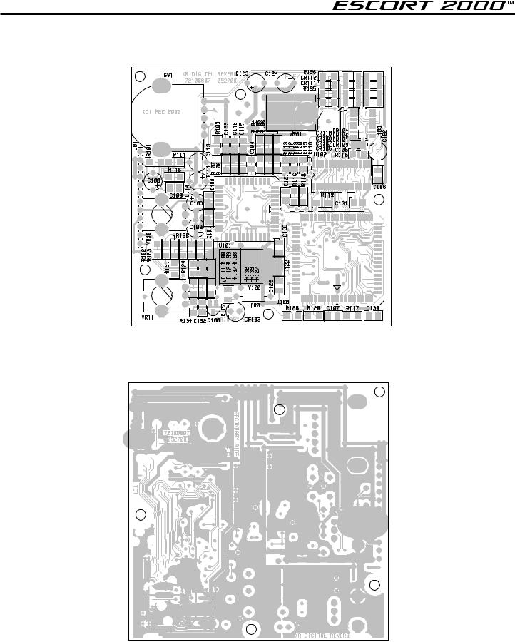
PCB LAYOUT
DSP REVERB PCB
(Top View)
(Bottom View)
- 7 -

PCB LAYOUT
Power Amp PCB
- 8 - |
 Loading...