

Page 1
SPECIFICATIONS Versarray™ 112
Features:
• 2-way Bi-Amp Ribbon Line Source Array
SR System
• 12" Neo Black Widow 4" VC Woofer
• 1,000 watt program, 2000 watt peak
power handling
• Ribbon Tweeters with Neo magnet and
composite material sandwich ribbon
• 90° H by 15° V coverage pattern
(per one cabinet)
• Easy aiming angle adjustment rigging
system
• Angle adjustable in 2 1/2 degree
increments from 0 to 15 degrees, total
angle between adjacent cabinets
• Sound Guard tweeter protection
• Dual stand mount cups, one
perpendicular, one 5° angled down
• Inputs are two Neutrik Speakon 4-pin
jacks in parallel
• 18 mm 13-ply Baltic birch enclosure
Description
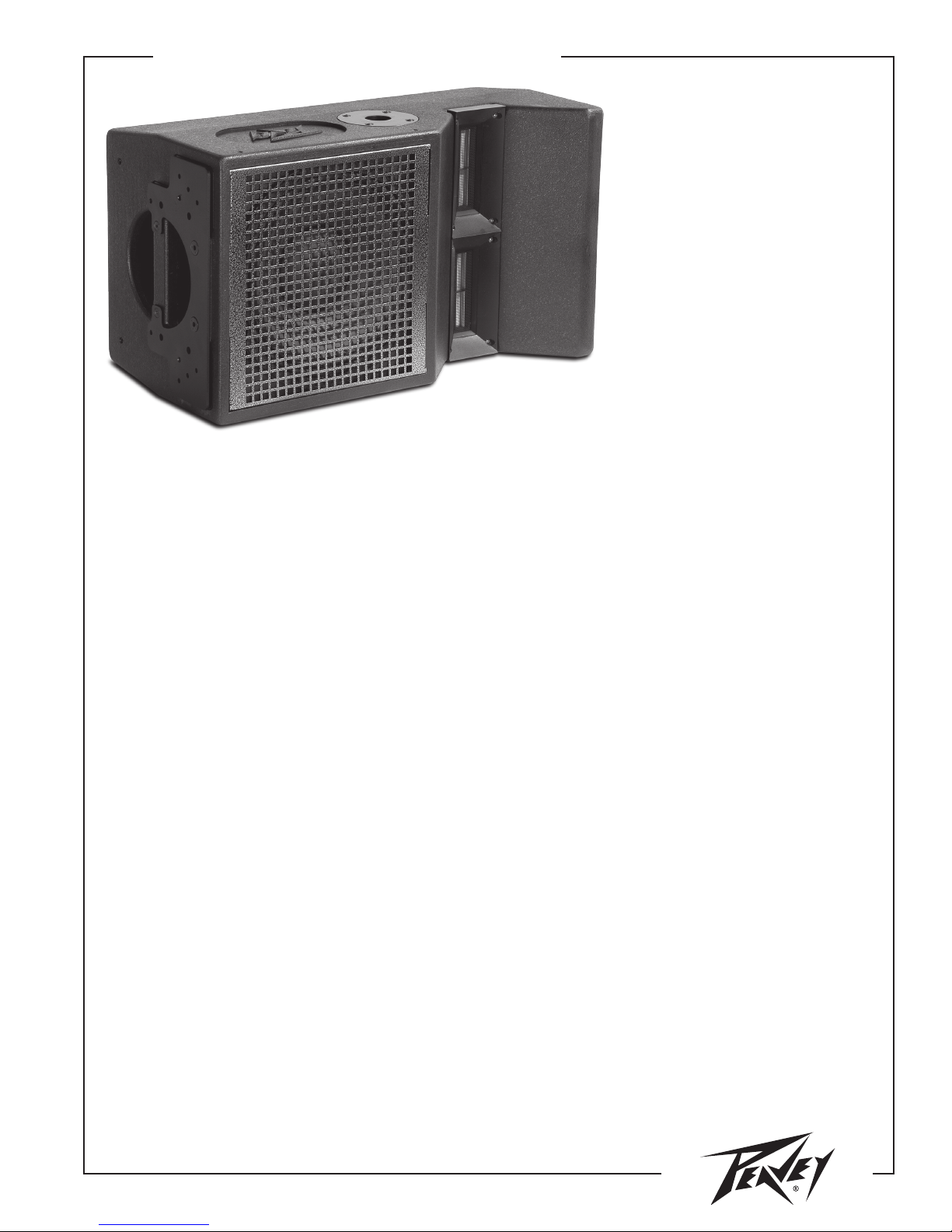
The Versarray 112 Ribbon Tweeter Line Source Array module consists of a new 12" Neo Black Widow® woofer combined with a
Neodymium based Peavey RD™ 1.6 ribbon tweeter in a cabinet with a highly flexible rigging system. Designed to provide modular
coverage of small to medium venues, and intended for use with the companion Versarray Sub models, the Versarray 112 offers
extreme versatility for such high performance capability.
The two-way system consists of a 12" Black Widow Neo series woofer with a Neodymium magnet structure, capable of handling
over 500 watts of continuous power, and two Peavey RD 1.6 ribbon tweeters utilizing a composite sandwich ribbon, a Neodymium
magnet system, and a low distortion waveguide.
Full range input connection to the system is made via two 4-pin Neutrik® Speakon® jacks. The total impedance presented by the
ribbons can be adjusted to 16 ohms or 4 ohms via an internal jumper on the input cup, providing flexibility in how the line array
is wired for your amplifier application. Sound Guard™, Peavey's proprietary protection circuitry, provides long and medium term
driver overload protection for the tweeter without impairing musical transients or dynamics.
The adjustable rigging system allows a classic straight line array configuration, or a number of different angling options for
aiming the system easily. Angles between the array modules are adjustable from 0 degrees (straight), to 7.5 degrees in 2.5 degree
increments. Total angle between two cabinets is 15 degrees. This provides the capability to create a completely straight line array
of 6 or more modules, or a curved array of 6 or more modules, with a recommended maximum total of 5 degrees of angle between
each module for continuous and even coverage, for a total vertical coverage pattern of up to 40 degrees, or somewhere in between
a 5 degree pattern (straight line array) and a 40 degree pattern (8 cabinets with 5 degree curve).
Bolts are supplied with the rigging hardware to couple the Versarray 112 modules together and lock the angles between them into
place, but optional quick release pins are available for quick and easy field adjustments or re-configurations of a line array.
The flexibility of the Versarray™ system allows the use of 1 to 8 or more Versarray 112 modules in conjunction with anything from
one Versarray 118 Sub to a pair of Versarray 218 Subs.
Two stand mount cups on the Versarray 112 allow for stand mounting at either a standard straight ahead angle, or a 5 degree
tilt down for better crowd coverage.
A pole tunnel is built into the Versarray 118 Subwoofer so that one or two Versarray 112 speakers can be mounted on the
Versarray system-specific pole.
An optional special bracket set mounts to the Versarray 218 Sub, and allows up to three of the Versarray 112’s to be mounted
on top of the Versarray 218 Sub, and angled upward, for use on stage in a stadium seating situation.
A lift kit co-designed with Vermette is available as a Versarray system accessory. The Vermette list can elevate up to six
Versarray 112 modules 13 feet high above a Versarray 218 Sub, and then fold down for easy transportation and storage.
Page 2

SPECIFICATIONS Versarray™ 112
Frequency response, 1 meter on-axis,
swept-sine in anechoic environment:
110 Hz to 20 kHz (±3 dB, with processing)
Usable low frequency limit
(-10 dB point):
85 Hz (with processing)
Power handling:
Low Frequency Section:
500 W continuous
1,000 W program
2,000 W peak
High Frequency Section:
80 W continuous
160 W program
320 W peak
Sound pressure level, 1 watt, 1 meter
in anechoic environment:
Low Frequency Section:
96 dB SPL, (2.83 V input)
High Frequency Section:
99 dB SPL, (4.0 V input for 16 ohm wiring;
2.0 V for 4 ohm wiring)
Maximum sound pressure level
(1 meter)*:
Low Frequency Section:
123 dB SPL continuous
129 dB SPL peak
130 dB SPL measured peak**
High Frequency Section:
118 dB SPL continuous
124 dB SPL peak
130 dB SPL measured peak***
*Note: This spec is for one module at 1 meter. A line
array of 6 units has much higher output at distance
due to line source effect where SPL falls of at 3 dB per
distance doubling rather than 6 dB.
**Note: This is measured using transient tone burst
signals with a crest factor of 12 dB, and over 4,000W of
power available.
***Note: This is measured using transient tone burst
signals with a crest factor of 12 dB, and over 1,200W of
power available.
Nominal Radiation Angle measured at
-6 dB point of polar response:
90 degrees Horizontal by 15 degrees
Vertical
(One module only, straight line array of more than 1
module narrows vertical dispersion accordingly)
Radiation angle measured at -6 dB
point of polar response:
500 Hz – 1.6 kHz:
Horiz. 120o +/- 55o
Vert. 117o +/- 75o
1.6 kHz - 5 kHz:
Horiz. 84o +/- 20o
Vert. 34o +/- 20o
5 kHz - 16 kHz:
Horiz. 94o +/- 5o
Vert. 15o +/- 3o
Directivity factor, Q (Mean):
19.78 +19.4, -17.4
Directivity index, Di (Mean):
11.44 dB +4.5 dB, -7.6 dB
Transducer complement:
Low Frequency Section:
1 x 12" Woofer,
1212-4 Neo Black Widow® 4" VC
Woofer, in a sealed box
High Frequency Section:
2 x 4.75 in. Ribbon Tweeters
Two RD™ 1.6 Peavey Ribbon Tweeters,
on a waveguide
Box tuning frequency (sealed):
Low Frequency Section: 100 Hz
Harmonic distortion*:
1W power
Second Harmonic:
200 Hz: 0.18 %
1 kHz: 0.15 %
4 kHz: 0.09 %
Third Harmonic:
200 Hz: 0.22 %
1 kHz: 0.48 %
4 kHz: 0.12 %
10W power
Second Harmonic:
200 Hz: 0.71 %
1 kHz: 0.73 %
4 kHz: 0.42 %
Third Harmonic:
200 Hz: 0.19 %
1 kHz: 0.74 %
4 kHz: 1.08 %
*Note: Distortion levels may be measurement setup
limited in some instances
Electroacoustic Crossover Point,
Peavey Active Digital Crossover:
(Applies to Digitool and VSX settings provided by Peavey)
Sub–Low Frequency:
120 Hz at 24 dB/octave
Low Frequency–High Frequency:
1800 Hz at 24dB/octave
Recommended active crossover
frequency region and slope:
Sub –Low Frequency:
125 Hz at 24 dB/octave LR
Low Frequency – High Frequency:
2000 Hz at 24 dB/octave LR
Time offset:
Low Frequency:
Ahead of tweeter by 0.073 ms
Impedance (Z):
Low Frequency:
Nominal: 8.0 Ω
Minimum: 6.5 Ω
Passive HF:
Nominal: 16 Ω or 4 Ω
Minimum: 13.6 Ω or 3.4 Ω
Input connections:
2x Neutrik® 4-pin Speakon® jack
Enclosure materials & finish:
18 mm 13-ply Baltic birch plywood
finished in black or white painted finish,
perforated steel grille finished in silvervein powder coat paint.
Mounting provisions:
Custom array brackets and hardware, and
a custom array angle adjustment system
are included with each module. Quick
release pins, and a crank-lift system codesigned with Vermette specifically for
the Versarray system, are available as
accessories.
Dimensions (H x W x D):
Front:
14.06 in. x 25.25 in. x 11.75 in.
357 mm x 641 mm x 298 mm
Rear:
12.62 in. x 25.25 in. x 11.75 in.
321 mm x 641 mm x 298 mm
Net Weight:
54 lbs. (24.5 kg)
(includes two of the rigging coupling brackets)
Companion Subwoofers
(sold separately):
Versarray™ 118 Sub single 18"
Lo Max® woofer subwoofer
Versarray™ 218 Sub double 18"
Lo Max® woofer subwoofer
Optional Accessories:
Custom Vermette Lift, for flying arrays
(Peavey part number 00595760); Peavey
Array Fly Bar (Peavey part number
00584970) A Versarray™ subwoofer
stand mount pole (Peavey part number
00584860); 3 foot speaker cable, with 16
gauge 4 conductor wires with 4-pin to 4-pin
Neutrik connectors (Peavey part number
00585240); and Quick Release Positive
Lock Pins (Peavey part number 00594020
for a set of four) for array rigging.
2
Page 3
SPECIFICATIONS Versarray™ 112
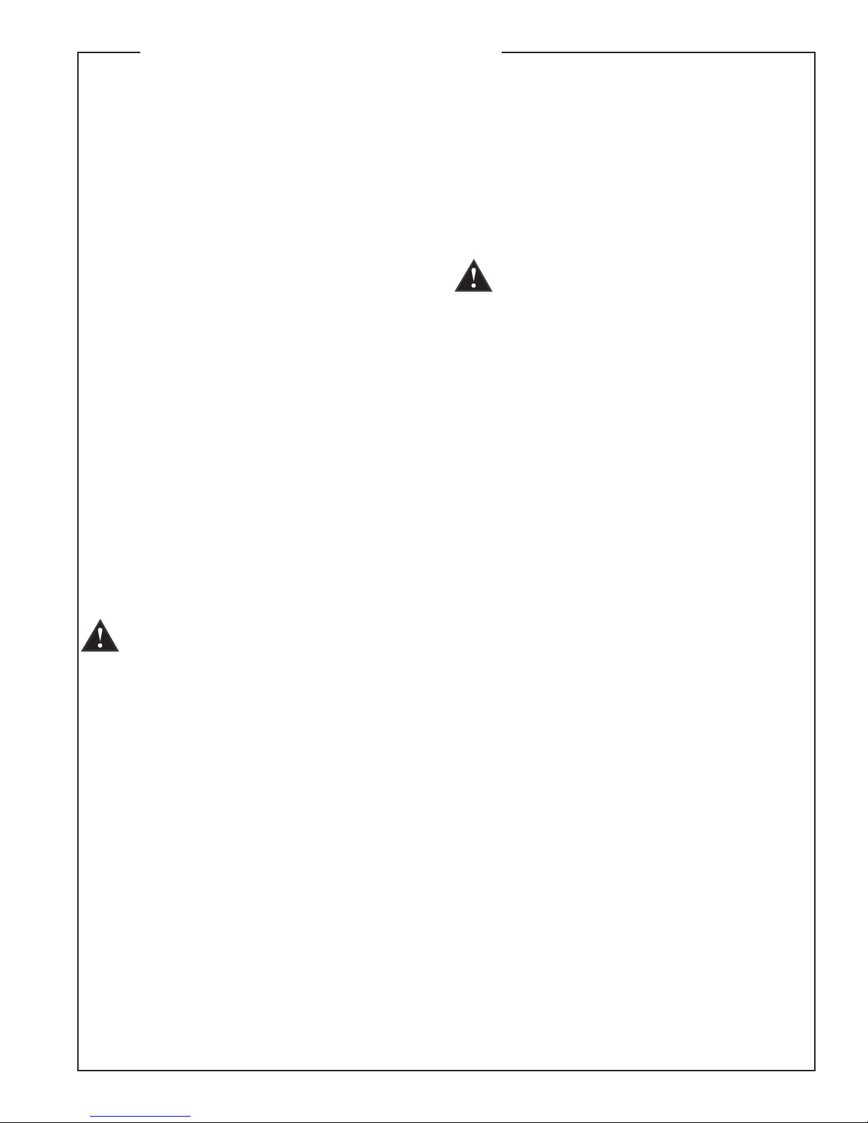
Frequency Response
This measurement is useful in determining how accurately a given unit
reproduces an input signal. The frequency response of the Versarray 112
is measured at a distance of 1 meter using a 1 watt (into the nominal
impedance) swept-sine input signal. As shown in figure 1, the selected
drivers in the Versarray 112 combine to give a smooth frequency response
from 110 Hz to 20 kHz, with signal processing.
Directivity
Beamwidth is derived from the -6 dB points from the polar plots which
are measured in a whole space anechoic environment. Q and Directivity
Index are plotted for the on-axis measurement position. These are
specifications that provide a reference to the coverage characteristics
of the unit. These parameters provide insight for proper placement and
installation in the chosen environment. The blending of the components
of the Versarray 112 and the Peavey VSX™ 26 or Peavey Digitool™ MX
speaker processor and crossover with the Versarray 112 pre-sets, exhibit
a desirable beamwidth and directivity (figure 3 & 4) suitable for sound
reinforcement applications.
Power Handling
There are many different approaches to power handling ratings. Peavey
rates this loudspeaker system's power handling using the AES Standard
2-1984. Using audio band pink noise of the proper range for each
driver, with peaks of four times the RMS level, and then running the
signal through either the Peavey VSX 26 or Peavey Digitool MX speaker
processor and crossover with the Versarray 112 pre-sets, this strenuous
test signal assures the user that every portion of this system can
withstand today's high technology music. This rating is contingent upon
having a minimum of 3 dB of amplifier headroom available.
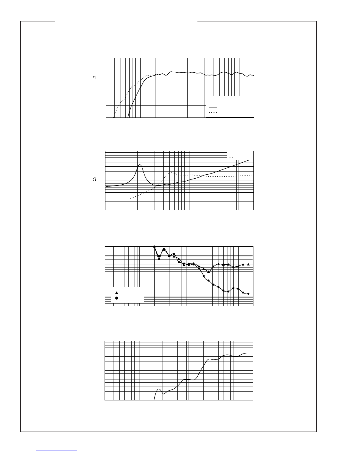
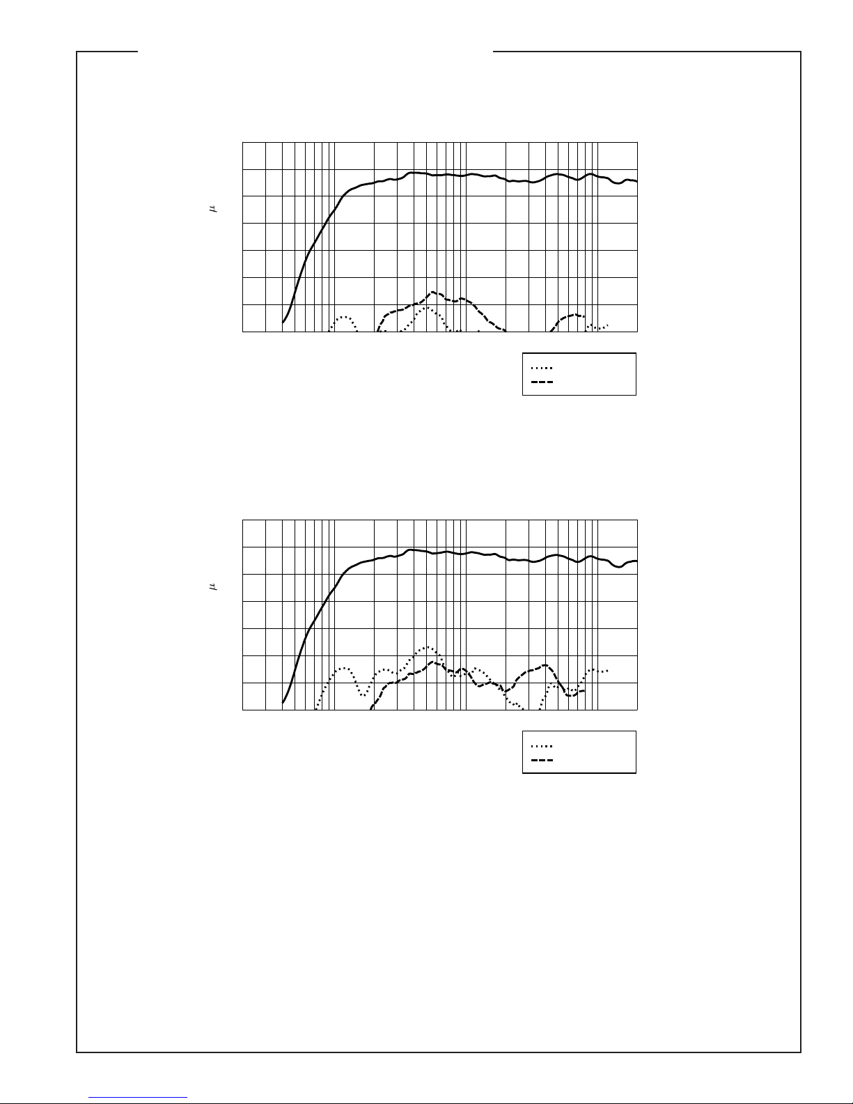
Harmonic Distortion
Second and third harmonic distortions vs. frequency are plotted in figures
5 & 6 for two power levels. Those levels are one watt of input power and
ten watts of input power, to the woofer, at 1 kHz. Distortion is read from
the graph as the difference between the fundamental signal (frequency
response) and the desired harmonic. As an example, a distortion curve
that is down 40 dB from the fundamental is equivalent to 1% distortion.
Mounting
Caution: Before attempting to suspend this speaker, consult a
certified structural engineer.
Speaker can fall from improper suspension, resulting in serious
injury and property damage. Other enclosures may be suspended below
one. However, the combined weight of additional enclosures and all
cables, clamps and other hardware must not exceed 270 pounds. The
Versarray 112 weighs 54 pounds and the maximum combined weight
suspended from the uppermost mounting bracket assemblies must not
exceed 324 pounds. Maximum enclosure angle 45°. Use only the correct
mating hardware. All associated rigging is the responsibility of others.
Architectural & Engineering Specifications
The loudspeaker system shall be a two-way, sealed enclosure with a builtin cabinet-to-cabinet rigging and angle adjustment system included. The
unit shall have an operating bandwidth of 110 Hz to 20 kHz, with signal
processing. The nominal output level of the woofer shall be 96 dB, and
of the tweeters 99 dB when measured at a distance of one meter with an
input of one watt. The nominal impedance shall be 8 ohms for the woofer,
and internally switchable to either 4 or 16 ohms for the tweeters. The
maximum continuous power handling for the woofer shall be 500 watts,
maximum program power of 1,000 watts and a peak power input of at
least 2,000 watts, and for the tweeters it shall be 80 watts continuous,
maximum program power of 160 watts and a peak power input of at
least 320 watts, with a minimum amplifier headroom of 3 dB. The woofer
shall be a Peavey Black Widow® Neo series, with a 4" voice coil, and the
two tweeters shall be a Peavey RD™ 1.6 with true ribbon construction,
transformer coupled to the driving amplifier used. The tweeters shall be
provided with a self-resetting protection circuit internal to the cabinet to
help prevent damage to the tweeters during a power overload condition.
Input shall be via two Neutrik Speakon type 4-pin jacks connected in
parallel.
The nominal radiation geometry shall be 90 degrees in the horizontal
plane and 15 degrees in the vertical plane for a single Versarray 112
cabinet. There shall be stand mount cups provided for stand use, one cup
on one side for a stand angle perpendicular to the cabinet side, the other
cup on the other side angled 5 degrees down from perpendicular, with
regard to the front of the cabinet.
The outside dimensions shall be 14.06 inches high by 25.25 inches wide
by 11.75 inches deep. The cabinet shall be constructed of 18 mm 13 ply
birch plywood. The weight shall be 54 pounds. The loudspeaker system
shall be a Peavey model Versarray 112.
Caution! Important Safety Information for Rigging and
Flying the Versarray 112 Speaker System
Caution: Before attempting to suspend these speakers, consult
a certified structural engineer. The speaker can fall from improper
suspension, resulting in serious injury and property damage.
Other enclosures may be suspended below one Versarray 112 cabinet.
However, the combined weight of additional enclosures and all
cables, clamps, and other hardware must not exceed 378 pounds. The
Versarray 112 weighs 54 pounds and the maximum combined weight
suspended from the uppermost mounting bracket assemblies must not
exceed 432 pounds.
Before you fly the array, be sure to inspect the rigging and flying
hardware to insure that it is mechanically sound and has not been
damaged, there should be no significant distortion of the shape of the
coupling brackets, cabinet brackets, or fly bar, and the hardware should
be checked for tightness.
IF ANY OF THE BRACKETS, OR THE FLY BAR HAS BEEN DAMAGED OR
DISTORTED, DO NOT USE, AND DO NOT FLY THE ARRAY UNTIL THEY CAN
BE REPLACED OR REPAIRED!
DO NOT USE THE COUPLING BRACKETS AS HANDLES TO TRANSPORT
THE CABINETS!
Use only the correct mating hardware. All associated rigging is the
responsibility of others.
Warning! Do not feed a full-range signal to the tweeters in the Versarray
112! This could damage the tweeters and/or the driving amplifier!
These ribbon tweeter diaphragms are transformer coupled to the power
amp, and present a very low impedance load below 300 Hz.
It is recommended that for set-up or testing purposes, a high frequency
sweep starting or ending no lower than 300 Hz be used to verify that the
tweeters are connected to the high frequency output of the crossover/
processor. If the wiring has been swapped, and the signal is mistakenly
fed to the woofers, output will fall off significantly above 5 kHz. Always
double-check and test your wiring before applying any music signals
to the system! The ribbon tweeters are connected to the Neutrik®
Speakon® pins 2+ and 2-, as per industry standards.
If there is any chance that trained personnel are not going to be
connecting and operating the system, then it would be advisable to place
a high quality polypropylene film cap in series with the tweeters, 40 uF for
a 4 ohm wiring, and 10 uF for a 16 ohm wiring.
Caution! Ribbon Tweeters do not exhibit audible signs of distress when
overloaded! It is possible to exceed the physical and/or thermal limits by
overloading the unit suddenly with excess power, even though there are
no obvious sounds of distress.
CAUTION! In order to prevent damage to the ribbon tweeters, keep the
Versarray 112 system away from metal filings at all times. Do not expose
ribbons to blasts of air, and do not use canned air to spray the ribbons,
as this can result in damage. Do not expose ribbons to liquids or caustic
fumes, and keep away from salt spray.
3 + 2 YEAR LIMITED WARRANTY
NOTE: For details, refer to the warranty statement. Copies of
this statement may be obtained by contacting Peavey Electronics
Corporation, P.O. Box 2898, Meridian, Mississippi 39301-2898.
3
Page 4
SPECIFICATIONS Versarray™ 112
20 50 100 200 500 1k 2k 5k 10k 20k
Frequency (Hz)
60
70
80
90
100
110
dB SPL (re 20 Pa)
Amplitude Response (1m Equivalent On-Axis)
No LF Crossover
With Crossover
VR112 Only
Figure 1
20 50 100 200 500 1k 2k 5k 10k 20k
Frequency (Hz)
1
10
100
Q & Directivity Index
Q
Figure 4
20
10
Di
0
20 50 100 200 500 1k 2k 5k 10k 20k
Frequency (Hz)
5
10
20
30
40
60
80
100
140
180
300
360
Beamwidth (Degrees)
Beamwidth
Vertical
Horizontal
Figure 3
20 50 100 200 500 1k 2k 5k 10k 20k
Frequency (Hz)
1
2
3
5
10
20
30
50
100
Impedance
High Frequency
Mid Bass
Z
( )
Figure 2
4
Page 5
SPECIFICATIONS Versarray™ 112
20 50 100 200 500 1k 2k 5k 10k 20k
Frequency (Hz)
50
60
70
80
90
100
110
120
dB SPL (re 20 Pa)
Harmonic Distortion : 10W Power
Figure 6
3rd Harmonic
2nd Harmonic
20 50 100 200 500 1k 2k 5k 10k 20k
Frequency (Hz)
40
50
60
70
80
90
100
110
dB SPL (re 20 Pa)
Harmonic Distortion : 1W Power
Figure 5
3rd Harmonic
2nd Harmonic
5
Page 6

SPECIFICATIONS Versarray™ 112
Input Cup
6
Page 7

SPECIFICATIONS Versarray™ 112
11.625
13.875
24.918
WITHOUT BRACKET
25.184
WITH BRACKET
11.625
25.184
WITH BRACKET
24.918
WITHOUT BRACKET
Dimensions
7
Page 8

SPECIFICATIONS Versarray™ 112
Using the Versarray 112
General Usage Notes
Note that the Versarray 112 is intended to be used with a subwoofer, an electronic crossover, and three channels of amplification to
provide full range performance. The Versarray 112 is not a full range system by itself, and after bi-amplification and EQ, only covers
the range from approximately 125 Hz and up. A number of suitable crossover options are available from Peavey: the Peavey VSX™ 26
Loudspeaker Management System, the VSX 48 Loudspeaker Management System, and the Peavey Digitool™ MX. These Peavey products
provide pre-configured set-up files that include an optimized crossover, an EQ tuned for flat response, and proper level settings that
serve as a starting place for any permanent installation.
There are two subwoofers in the Versarray™ product family that are designed to be used with the Versarray 112 module; the Versarray
118 Sub and the Versarray 218 Sub.
Using a single Versarray 112 pole mounted over a Versarray 118
While the Versarray 112 is meant to be used in multiple cabinet arrays, it can be used as a single cabinet as long as it has a subwoofer
to provide the frequencies below 125 Hz.
The Versarray 112 has a very narrow vertical coverage pattern of approximately 15 degrees. Because of this, it should be aimed accurately
at an angle that will cover the desired space. There are two different pole mount cups on the Versarray 112, one that provides an angle of
0 degrees to perpendicular, and a cup on the other side that provides an angle of 5 degrees down from perpendicular.
Using a combination of the height of the enclosure (where the sub is placed, such as up on a stage, or down on the floor) and the two
angles, be sure to aim the coverage pattern of the Versarray 112 at the desired listening space.
Using Multiple Versarray 112’s mounted over a Versarray 118/218 Sub
The rigging plate hardware allows up to two coupled cabinets to be arrayed over a Versarray 118 on a pole, and up to three coupled
Versarray 112’s mounted over a Versarray 218 with the use of an optional subwoofer mounting bracket set. With the angle between
cabinets adjustable in 2.5 degree increments, the second (or third) cabinet can be aimed as needed at the coverage area.
We do not recommend more than two Versarray 112 cabinets be pole mounted over a Versarray 118 Sub, or more than three cabinets
above a Versarray 218 Sub.
Using the Versarray 112 in a Line Source Array
Set-up and use of line arrays differs considerably from typical point source speaker systems, or arrays of point source speaker systems.
In addition, the Versarray 112 has a versatile rigging system that allows a substantial range of adjustment and abundant options for
aiming the loudspeakers. In this section, we will discuss how to best use the Versarray 112 in line arrays, and how to set the angle
adjustments between cabinets.
There are three major aspects to configuring and using a line array: choosing the geometry (or the curved shape) of the line array,
aligning and aiming the complete line array, and equalizing the line array in its final form.
Line Array Geometry
Classic line arrays used a simple straight line geometry that provided the classic “laser beam” vertical coverage pattern that has become
associated with line arrays today. However, many do not realize that the vertical coverage pattern is extremely tight and limited, typically
not extending vertically past the ends of the array at a distance.
Accurate measurements of the amount of angular coverage are difficult with line arrays, because the effective coverage angle keeps
getting smaller as you get further and further away, until it approaches a fraction of a degree at some very far distance.
The upshot of this is that unless you truly need the extremely tight vertical coverage pattern, AND can successfully aim the entire array
at the exact spot you wish to cover, a classic straight line geometry is not going to be the best choice. A more useful and general-purpose
geometry is a gentle and continuous curve, with the angle between each cabinet a total of 2.5 degrees. This would provide approximately
18 degrees of seamless vertical coverage with a 6 cabinet array, and maintain a fairly smooth frequency response. This creates a system
with a coverage pattern of approximately 90 degrees horizontal and 18 degrees vertical.
If the venue is smaller, or needs a more open vertical pattern for coverage, then there are several options that can address this. You can
increase the angle between all the cabinets to 5 degrees total, providing a vertical coverage of approximately 30 degrees.
If that is too much vertical coverage, but there are still some seats up front that need to be covered, then there are two other recommended
geometries to use. One is a dual radius, as pioneered by Peavey on the Peavey SSE™ LA. The upper 3 cabinets would be set to a total
angle between cabinets of 2.5 degrees, while the bottom three would be set to 5 degrees. This arrangement provides a smooth, seamless
vertical coverage pattern of approximately 28 degrees.
The other geometry is a modification of the classic “J” line, using a continuously curved array for the top section instead of a straight line,
and then an abruptly curved section for the bottom few cabinets. This might consist of the top 4 or 5 cabinets angled at 2.5 or 5 degrees,
with the bottom one or two each angled the maximum amount of 15 degrees total. Up until now, we have been talking about a relatively
smooth vertical coverage, with no gaps or suck-outs in the vertical pattern. However, the use of the “J” precludes this due to the sharper
angles between the individual bottom cabinets. Anything over about 5 degrees total angle between cabinets will tend to cause a “gap’
or a “hole” in the response at certain frequencies, and while it is not too bad, the sharper the angle, the worse it gets.
Why not use a classic “J” line geometry? This combines the narrow “laser beam” pattern with a “gaps in the coverage” pattern, combining
the worst of both worlds. This is why we recommend one form or another of a gentle and continuous curve, to avoid these common
problems, and provide maximum performance.
8
Page 9

SPECIFICATIONS Versarray™ 112
Using the Versarray 112
Aiming the Line Array
If a classic straight line array geometry is used, then aiming becomes critical; coverage pattern at high frequencies will only be about
7.5 feet tall for a set of six Versarray 112 cabinets. You will need to pick the 7.5 feet of vertical space you want covered very carefully,
and aim the array precisely. Here, use of an inexpensive laser pointer temporarily taped to the top and/or bottom of the array can be an
invaluable aiming aid.
If you have chosen one of the geometries that provide a smooth curvature and a relatively narrow vertical coverage, then aiming will
be more in line with the kinds of concerns and methods used for high Q point sources, but you still must pay attention to assuring that
seating areas of primary concern are within that pattern.
If you have chosen one of the dual radius curvatures, the top section will be handling the long throw coverage, and the bottom section
will be providing the short throw coverage. Once again, use of the familiar tools for aiming point sources and clusters will be helpful here,
as long as you realize that you have two different coverage zones.
Peavey has teamed with EASE Focus software to provide you access to line array aiming software for configuring your Peavey Versarray
system. Check with your Peavey representative, or visit the Peavey web site for download information.
Equalizing the Line Array
The sad truth of the matter is, you cannot EQ a line array using a single microphone position or even several different mic positions
averaged out, unless special techniques are used and fully understood. Due to the way a line array works, it just isn’t very accurate to
try and use point source techniques for EQ.
It is strongly advised that you do not try to use a single mic placed out in the listening area, and use an RTA or other spectrum analyzer to
try and “fix” things, as the single mic location will create an erroneous impression of what is going on. Line arrays have special properties
that make equalizing via measurement much more difficult to do without taking a lot more variables into account.
Peavey provides proper settings for the Versarray system within our digital signal processors/crossovers, the VSX™ series and the
Digitool™ MX. These settings provide a nominally flat response from the Versarray system, and can be used as the best starting point
for line array use in most any venue. Once you have the system up and running with these settings, minor overall tonal balance changes
can be made BY EAR to suit that particular venue and situation.
Listen for overall EQ for the room only, which should involve simple tone control type adjustments, rather than several 1/3 octave EQ
or parametric EQ adjustments. Instead, the use of a shelf filter for boost or cut at the frequency extremes as a whole would be more
appropriate.
Processor Settings
Check with Peavey Electronics Corp., or visit the Peavey web site at http://www.peavey.com for the latest crossover and EQ setting
information.
Assembling and Flying the Array
Caution: Before attempting to suspend this speaker, consult a certified structural engineer. Speakers can fall from improper
suspension, resulting in serious injury and property damage. Use only the correct mating hardware. All associated rigging is
the responsibility of others.
The coupling brackets can be mated to the Versarray 112 cabinet brackets by using the supplied 1/4" x 20 x 1.25" hex head grade-5 bolts
OR by using the optionally available Quick Release Positive Lock Pins (Peavey part number 00594020 for a set of four pins). If more of
the grade-5 bolts are needed, please order Peavey part number 71501019.
If bolts are used, a lock washer should be placed between the bolt head and the bracket, and the bolt tightened firmly. If the Quick
Release Positive Lock Pins are used, they should be fully seated, so that the C-clamp near the middle of the pin has been placed nearly
flush with the side of the bracket. You should not be able to pull these pins out unless the center push-button is fully depressed.
On the following pages are diagrams of how the bolts/pins should be placed to achieve the various angles in which the rigging hardware
may be set. Note that once the angle has been set, that one of the pins in a rotation slot may be removed, and the cabinets flown with
two pins/bolts per cabinet/per side, for a total of 4 pins/bolts per side.
If you are not sure how to assemble the rigging or how to fly the array once it has been arrayed, consult a certified structural engineer.
Before you fly the array, be sure to inspect the rigging and flying hardware to insure that it is mechanically sound and has not been
damaged, there should be no significant distortion of the shape of the coupling brackets, cabinet brackets, or fly bar, and the hardware
should be checked for tightness.
IF ANY OF THE BRACKETS, OR THE FLY BAR HAS BEEN DAMAGED OR DISTORTED, DO NOT USE, AND DO NOT FLY THE ARRAY
UNTIL THEY CAN BE REPLACED OR REPAIRED!
DO NOT USE THE COUPLING BRACKETS AS HANDLES TO TRANSPORT THE CABINETS!
Use only the correct mating hardware. All associated rigging is the responsibility of others.
9
Page 10

SPECIFICATIONS Versarray™ 112
0°
0° 2 Pin
2.5° 5°
10
Page 11

SPECIFICATIONS Versarray™ 112
7.5°
10°
12.5°
15°
11
Page 12

SPECIFICATIONS Versarray™ 112
Detail A
?
Cabinet Fly Bar Diagram
12
Page 13

SPECIFICATIONS Versarray™ 112
Coupling Bracket Diagram
Cabinet Bracket Diagram
13
Page 14

NOTES:
SPECIFICATIONS Versarray™ 112
14
Page 15

SPECIFICATIONS Versarray™ 112
NOTES:
15
Page 16

Features and specifications subject to change without notice.
Peavey Electronics Corporation • 5022 Hartley Peavey Drive • Meridian, MS • 39305
(601) 483-5365 • FAX (601) 486-1278 • www.peavey.com
©2006 Printed in the U.S.A.
80305208
 Loading...