

Page 1
owners manual
V12 mixing console
Page 2

direct output features
This section is intended for use in Front of House operations to provide
a controlled feed to an external tape machine. It may also be used as a
localized effects send or monitor output. When the console is being used
for monitor mixing operations,this output is used as a dedicated send to
the Matrix section to generate custom versions of the Matrix mix for
monitor use by secondary artists such as horn sections or backing vocals.
DIRECT OUTPUT CONNECT OR - XLR Balanced Output - rear-panel
mode switch
When not depressed,all contr ols within this block affect the dir ect output
connector. When depressed, all front panel controls within this section
affect the Pan and assignment section of the console.
FDR pre switch
Selects the signal source of this section from its normal post fader sour ce
position to a Pre Fader signal source.
EQ pre switch
Selects the Pre Fader signal source between its normal Post EQ source
position to a Pre EQ signal source.
level control
Controls the Direct Output level when the Mode switch is NOT
depressed. When the Mode switch IS depressed, This level control will
feed the Pan/Assignment section of the module in place of the normal post
fader signal.
push–on/push–off
Located on level control pot,turns this section on and off with its status
displayed by the dual color LED next to this control.
hidden functions
When the Mode switch is depressed,the Direct Output signal source is
determined by internal jumpers. (Post Fader - Pre Fader - Pre EQ) An
additional jumper determines whether or not the Pre Fader signals are
controlled by the module’s mute system.
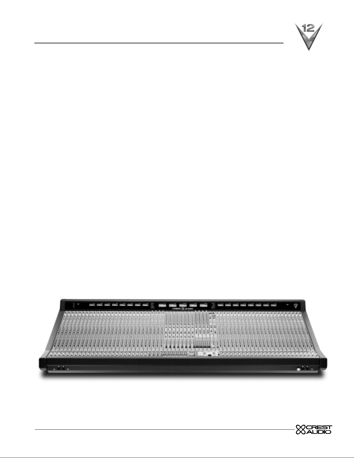
mono input module
p. 2
Page 3
p. 3
group assignment features
discrete group assignment switches 1–8
Assignment of post fader signal to discrete group buses unless the pan
switch is activated, in which case the signal is post pan pot. When the
mode switch within the Direct Output section is depressed, the signal
source disconnects from the channel’s main fader and instead obtains its
signal from the set of controls located above the assignment section.
pan–switch
Configures the discrete bus assignment switches to follo w the pan control
with left assigned to odd and right assigned to even mix buses.
mono assignment switch
Direct assignment of channel to mono mix bus.Normal signal source from
post fader. (When the mode switch depressed,the signal is sourced from
section above assignment area of console).
left/right assignment switch
Assigns post pan pot signals to left and right mix buses. (When the Mode
switch is depressed,the signal is sourced from section above assignment
area of console).
LCR switch
Reconfigures pan pot to LCR operation,requires the M and LR assignment
switches to also be selected. LCR operaton does not affect the pan to
group buses
pan control
Adjust panoramic image between the Left and Right outputs (Including
groups when pan on is selected) When LCR is selected,provides true
LCR panning between Left and Center and Center and Right buses. Signal
to pan is selected by Mode Switch as normal post fader signal or, when
switch is depressed, as a post direct level contr ol source (Monitor Mode).
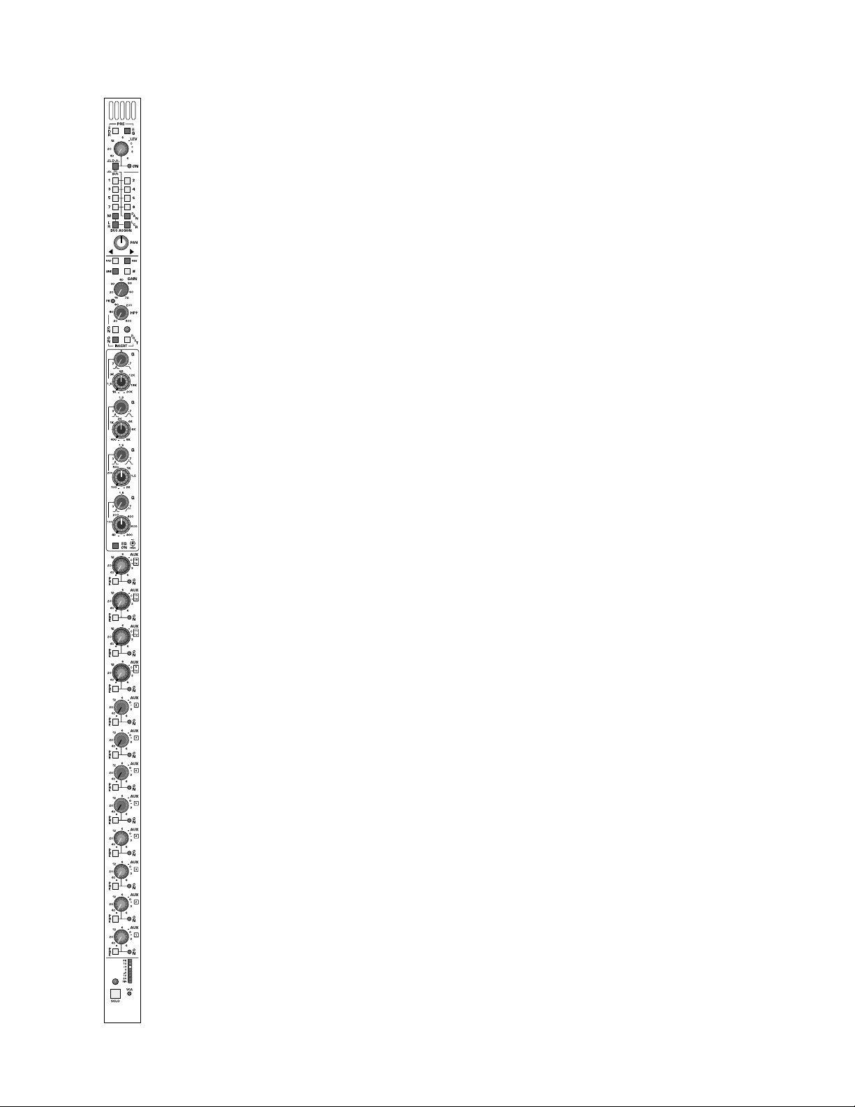
mono input module
Page 4
input features
pad switch
Inserts a 26dB pad into the microphone input circuit.
48-volt phantom power switch
Supplies 48 Volts to the microphone input. Will not operate if Line Input
is selected.
line input switch
Selects the line input circuitry using both the XLR and 1/4” phone jack. If
a connector is plugged into the 1/4” jack,the line input signal from the XLR
connector is defeated. (Note:Line input signal is NOT padded down as is
common in many consoles,but rather fed into another set of electronics
intended for line operation. The result is better noise performance compared to padding line lev el signal down and feeding the mic pre amplifier)
ground-lift switch
Lifts pin 1 of XLR connector from chassis ground. (on rear panel of
module)
input gain control
Adjusts the gain of the input preamp for both mic and line sources.
peak LED indicator
Red LED will illuminate if the pre-amplifier section comes within 3dB of
overload.
polarity reverse switch
Reverses the polarity of input signals (Both Mic and Line).
insert-on switch
Activates Insert return connector. Signal is always fed to balanced insert
send connector. Any equipment patched into the insert jacks will be
inserted into the channel signal path.
insert-post switch
Changes physical location of insert points from normal pre EQ position to
post EQ position.
INSERT SEND AND RETURN CONNECTORS - SEPARATE 1/4”
Balanced Send and Return connectors (on rear of module).
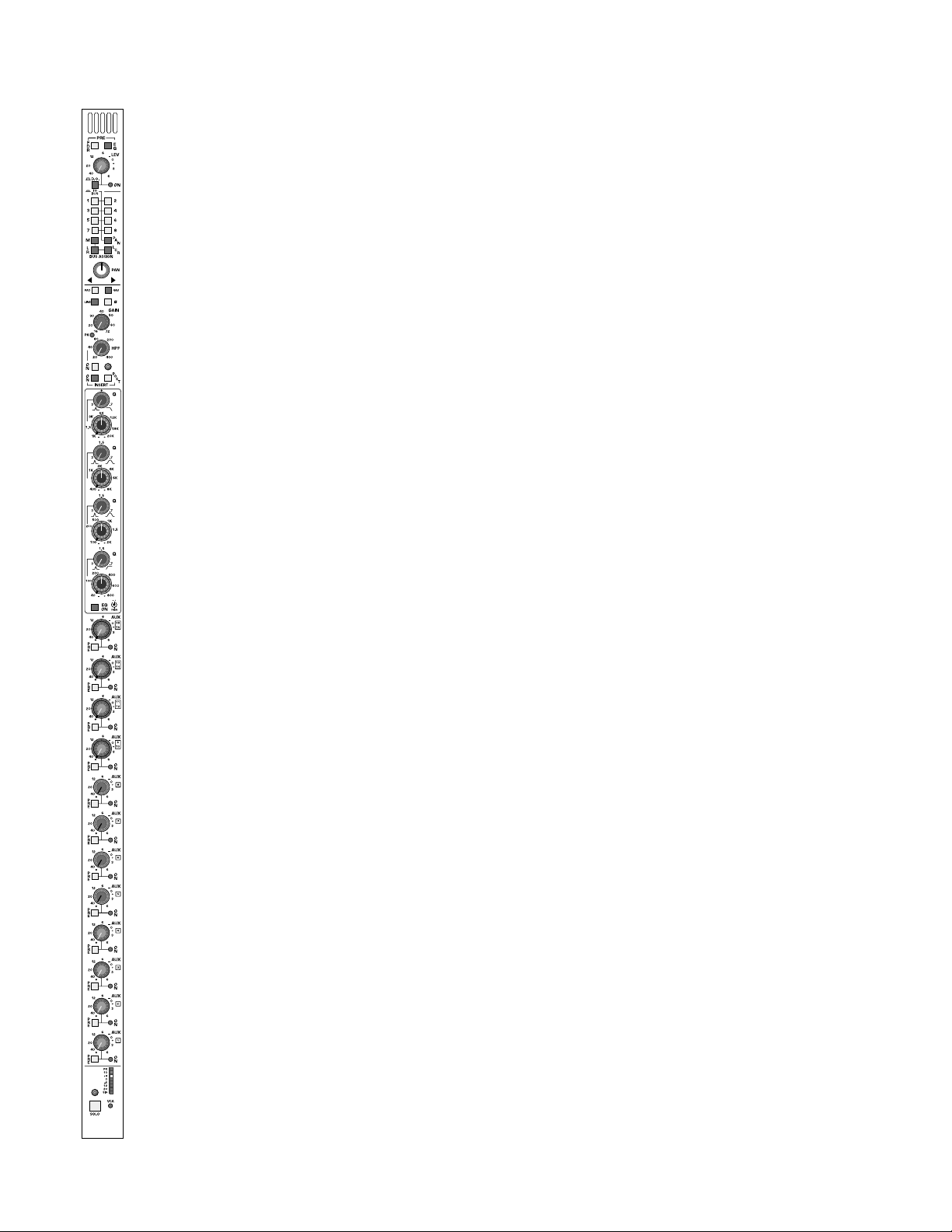
mono input module
p. 4
Page 5

p. 5
EQ features
high-pass filter on-switch
Turn on High Pass filter circuitry.
continuously-variable high-pass filter control
Sweep control variable between 20Hz and 400Hz at a -18dB per octave
rate.
high-frequency Q-control with shelf-switch
Adjust the Q of the high frequency section between 3.0 (Full Counter
Clockwise) and 0.7 (Clockwise). When turned beyond the widest bandwidth, the control has a switched position (Full Clockwise) that puts the
high frequency section into shelving mode.
high-frequency band amplitude and frequency contr ols
The inner-knob allows for up to ±15dB of boost/cut. The outer-knob
determines the center frequency of the band—adjustable from
1KHz–20KHz.
high-mid frequency Q-control
Adjust the Q of the high mid frequency section between 3.0 (Full Counter
Clockwise) and 0.7 (Full Clockwise).
high-mid frequency band amplitude and frequency contr ols
The inner-knob allows for up to ±15dB of boost/cut. The outer-knob
determines the center frequency of the band—adjustable from
400Hz–8KHz.
low-mid frequency Q-control
Adjust the Q of the low mid frequency section between 3.0 (Full Counter
Clockwise) and 0.7 (Full Clockwise).
low-mid frequency band amplitude and frequency controls
The inner-knob allows for up to ±15dB of boost/cut. The outer-knob
determines the center frequency of the band—adjustable from
100Hz–2KHz.
low-frequency Q-control with shelf-switch
Adjust the Q of the low frequency section between 3.0 (Full Counter
Clockwise) and 0.7 (Clockwise). When turned beyond the widest bandwidth, the control has a switched position (Full Clockwise) that puts the
low frequency section into shelving mode.
low-frequency band amplitude and frequency controls
The inner-knob allows for up to ±15dB of boost/cut. The outer-knob
determines the center frequency of the band—adjustable from
40Hz–800Hz.
EQ on switch
Inserts EQ section into the input module’s signal path.This switch has no
affect on the High Pass filter system.
mono input module
Page 6

aux features
aux send section 9/10,11/12,13/14,15/16
Four sets of dual concentric controls,each set having the following associated controls:
pre-fader switch
Selects the source of the signal for the dual concentric pair between the
normal post fader signal source to a pre fader signal source.
push-on /push-off switch
Inner control of dual concentric pot acts as an On/Off switch for the auxiliary send pair of signals (odd and even)
dual-color on-indicator
Each dual concentric control has a dual color LEDto indicate on/off/mute
status. When the aux pair is off,the LED is not illuminated. When the aux
pair is ON,the LED will illuminate GREEN. When the aux pair is ON but
MUTED,the LED will illuminate RED.
invisible mono/stereo switch 9/10,11/12,13/14,15/16
Electronic switching, controlled from within the master section, determines if odd and even pair aux sends ar e independent (Separate lev el controls) or configured as a ster eo pair with the inner contr ol providing level
functions and the outer providing odd/even pan functions.
TWO INTERNAL JUMPERs - select pre fader source as pre EQ or post
EQ for 9–12 and 13–16.Default setting is post EQ.
TWO INTERNAL DIP SWITCHES - set mute/no-mute functions for
9–12 and 13–16.Default setting is follow mute.
mono input module
p. 6
Page 7

p. 7
aux features
aux send section 5,6,7,8
Four rotary controls,each having the following associated controls:
pre-fader switch
Individual switches for each aux send selects the source of the signal
between the normal post fader signal source position to a pr e fader signal
source position.INTERNAL JUMPER - selects pre fader signals as pre or
post EQ (post EQ is default) internal dip switch determines whether pre
source follows channel mute or r emains un-muted (follow mute is default).
push-on/push-off switch
Control pot acts as an On/Off switch for the associated auxiliary send.
dual-color on-indicator
Each control has a dual color status indicator indication of on/off/mute status. When the aux send is off,the LED is not illuminated. When the aux
send is ON,the LED will illuminate GREEN. When the aux send is ON
but MUTED,the LED will illuminate RED.
INTERNAL JUMPER - selects pre fader source as pre or post EQ (post
EQ is default) and Mute/No Mute functions for all 4 aux sends within this
block.Internal dip switch determines whether pre source f ollo ws channel
mute or remains un-muted (follow mute is default).
aux send section 1,2,3,4
Four rotary controls,each having the following associated controls:
pre-fader switch
Individual switches for each aux send selects the source of the signal
between the normal post fader signal source position to a pre fader signal
source position. INTERNAL JUMPER - selects pre fader signals as pre or
post EQ (post EQ is default) internal dip switch determines whether pre
source follows channel mute or r emains un-m uted (f ollo w mute is default).
push-on/push-off switch
Control pot acts as an On/Off switch for the associated auxiliary send.
dual-color on-indicator
Each control has a dual color status indicator indication of on/off/mute status. When the aux send is off,the LED is not illuminated. When the aux
send is ON,the LED will illuminate GREEN. When the aux send is ON
but MUTED,the LED will illuminate RED.
INTERNAL JUMPER - selects pre fader source as pre or post EQ (post
EQ is default) and Mute/No Mute functions for all 4 aux sends within this
block.Internal dip switch determines whether pre source f ollo ws channel
mute or remains un-muted (follow mute is default).
mono input module
Page 8

monitor features
8-segment channel meter
Monitors a pre or post fader signal level as determined by a Master
Global POST switch within the master section of the console. Normally,
a pre fader signal is monitored. When the Global master switch is
depressed, ALL channel meters switch to a post fader monitor position
to prevent confusion betw een pre and post channel metering.The 8 segments include a dynamic signal present LED indicator which varies in
intensity to indicate the presence of any audio signal, and increases in
intensity until it reaches full brightness. When signal level reaches -15dB,
an additional LED will illuminate. Additional LED’s indicate at channel signal levels of -6dB,-3dB, 0dB, +3dB and +8dB.
The top red segment samples signals at a pre EQ position,post EQ position,and a post fader position. When any of these points approach 3dB of
clipping,this led will illuminate RED.This LED is NOT affected by the position of the Global Post Fader monitor switch.
VCA-level LED
This LED glows green to indicate the amount of control v oltage applied to
the channel VCA; the greater the control voltage, the brighter the LED.
Often,a channel may be assigned to more than one VCA master,and it is
easy to overlook an assignment and wonder why a channel isn’t on.This
LED gives the operator a quick refer ence to the state of the channel VCA;
if there is no LED indication,there is no VCA control voltage.The LED will
turn from green to r ed when the control voltage limit of +20dB is r eached
as detailed above.This alerts the operator to unusual or incorrect gain settings and prevents any additional fader boost from being applied.
solo switch
Will illuminate when manually selected in one of the console’s many Solo
modes. Controls within the master section determine if this switch will
sample signal pre fader or post fader/post pan pot.
Additional switches will determine the operating characteristics of the
Solo system. These may be selected from within the master section to be
NORMAL (cumulative), LAST PRESSED (Only one switch will be on at a
time.Selecting the next solo switch will automatically cancel the last switch
selected) or MOMENTARY (Solo system on only while switch is held
down). This Solo switch will also Solo and illuminate automatically if the
VCA master group that the channel may be assigned to is put into SOLO.
The SOLO system displays selected channels on individual Solo Left and
Solo Right meters. The signal also appears on separate Headphone and
Monitor output channels. The solo signal may also be routed to the
Alternate A/B and C/D outputs within the master section.
write-on strip
In the area separating the angled upper portion of the console and the
Fader bay area is a write in strip. This strip the primary module numbering,while providing write in area f or customer use.
mono input module
p. 8
Page 9

p. 9
Page 10
direct output features
This section is intended for use in Front of House operations to provide
a controlled feed of the modules separate left and right signals to an external tape machine. It may also be used as a localized effects send or monitor output. When the console is being used for monitor mix operations,
this output can be used as a dedicated send to the Matrix section to generate custom versions of the Matrix mix for monitor use.
DIRECT OUTPUT CONNECTORS - Separate Left and Right XLR
Balanced Outputs—on module rear-panel.
mode switch
When not depressed,all controls within this block affect the direct output
connectors. When depressed, all front panel controls within this section
affect the Balance and assignment section of the console.
FDR pre switch
Selects the signal sources of this section from its normal post ster eo fader
source position to a Pre Fader ster eo signal source.
EQ pre switch
Selects the Pre Fader signal source between its normal Post EQ stereo
source position to a Pre EQ ster eo signal source.
dual level control
Controls the amount of Left and Right signal feeding the dual direct output connectors when the Mode switch is NOT depressed. When the
Mode switch IS depressed, this level control will feed the
Balance/Assignment section of the module in place of the normal post
fader signal.
push–on/push–off
Located on the inside control of the dual concentric level control pot, it
turns this section on and off with its status displayed by the dual color
LED next to this control.
hidden functions
When the Mode switch is depressed,the Direct Output signal source is
determined by internal jumpers. (Post Fader - Pre Fader - Pre EQ) An
additional jumper determines whether or not the Pre Fader signals are or
controlled by the module’s mute system.
stereo input module
p. 10
Page 11

group assignment features
discrete group assignment switches 1–8
When the mode switch within the Direct Output section is depressed,the
stereo signal source disconnects from the channel’s post-fader point and
instead obtains its signal from the set of stereo contr ols located above the
assignment section.
sum switch
Configures the bus assignment switches to mono.The ster eo signal is normally assigned to the group buses with Left to odd,Right to even.
mono assignment switch
Summed Mono Direct assignment of channel to Mono mix bus.Normal
signal source is post fader .(When mode switch depressed,signal is sourced
from section above assignment area of console).
left/right assignment switch
Assigns stereo signals to Left and Right mix buses. (When mode switch
depressed, signal is sourced from section above assignment area of console).
LCR switch
Reconfigures center of dual concentric image control fr om LR balance to
LCR Balance. Note:Left/Right and Mono assignment switches must also
be depressed for proper operation.
image width control—WID
When the outside control of dual concentric pot is turned fully counter
clockwise, signal is presented to Left and Right outputs as a standard
stereo image. As the control is turned clockwise, the image decreases in
apparent width while maintaining a constant power output. When the
control is at its center detent a summed left/right signal results. As the
control is turned further clockwise, the image begins to widen, but as a
reverse image. When fully clockwise, the full stereo image exists, but is
reversed:left source now feeds right side;right source feeds left side.
image balance control
Center control of dual concentric pot controls balance of Left and Right
stereo signals. When the LCR switch is depressed,a summed mono signal is fed to the center (mono) channel. Var ying the center control will
determine the proportion of LR signal to the mono center signal while
maintaining a constant power output.Full CCW produces only L and R,
full CW produces only Center (Mono).
stereo input module
p. 11
Page 12

p. 12
input features
pad switch
Inserts a 26dB pad into the left and right microphone input circuit.
48-volt phantom power switch
Turns 48 Volts on to the microphone inputs. Will not operate if Line Input
is selected.
line input switch
Inserts a 26dB pad in to the input paths and disables the phantom power.
ground lift switch
Lifts pin 1 of XLR connectors from chassis ground (on r ear panel of module).
dual-concentric input gain control
Individually adjusts the gain of the input preamps.Left is inner control,right
is outer.
peak LED indicator
Red LED will illuminate if either of the pre-amplifier sections comes within 3dB of overload.
polarity-reverse switch
Reverses the polarity of the right input signal referenced to the left channel. An internal jumper can be reconfigured to reverse the polarity of both
input reference to other input modules.
insert-on switch
Activates Insert return connectors. Signal is always fed to balanced insert
send connector .Any equipment pated into the insert jacks will insrted into
the channel signal path.
LEFT AND RIGHT INSERT SEND AND RETURN CONNECTORS SEPARATE 1/4” Balanced Send and Return connectors—on rear -panel.
stereo input module
Page 13

EQ features
high-pass filter on-switch
Turn on High Pass filter circuitry.
continuously-variable high-pass filter control
Sweep control variable between 20Hz and 400Hz at a 18dB per octave
rate.
high-frequency Q-control with shelf-switch
Adjust the Q of the high frequency section between 3.0 (Full Counter
Clockwise) and 0.7 (Clockwise). When turned beyond the widest bandwidth, the control has a switched position (Full Clockwise) that puts the
high frequency section into shelving mode.
high-frequency band amplitude and frequency contr ols
The inner-knob allows for up to ±15dB of boost/cut. The outer-knob
determines the center frequency of the band—adjustable from
1KHz–20KHz.
high-mid frequency Q-control
Adjust the Q of the high mid frequency section between 3.0 (Full Counter
Clockwise) and 0.7 (Full Clockwise).
high-mid frequency band amplitude and frequency contr ols
The inner-knob allows for up to ±15dB of boost/cut. The outer-knob
determines the center frequency of the band—adjustable from
400Hz–8KHz.
low-mid frequency Q-control
Adjust the Q of the low mid frequency section between 3.0 (Full Counter
Clockwise) and 0.7 (Full Clockwise).
low-mid frequency band amplitude and frequency controls
The inner-knob allows for up to ±15dB of boost/cut. The outer-knob
determines the center frequency of the band—adjustable from
100Hz–2KHz.
low-frequency Q-control with shelf-switch
Adjust the Q of the low frequency section between 3.0 (Full Counter
Clockwise) and 0.7 (Clockwise). When turned beyond the widest bandwidth, the control has a switched position (Full Clockwise) that puts the
low frequency section into shelving mode.
low-frequency band amplitude and frequency controls
The inner-knob allows for up to ±15dB of boost/cut. The outer-knob
determines the center frequency of the band—adjustable from
40Hz–800Hz.
EQ on switch
Inserts EQ section into the input module’s signal path.This switch has no
affect on the High Pass filter system.
stereo input module
p. 13
Page 14

p. 14
aux features
aux send section 9/10,11/12,13/14,15/16
Four sets of dual concentric controls,each set having the following associated controls:
note:
Aux send 9 thru 16 are always fed as stereo:
left source feeds auxes 9,11, 13,15
right source feed auxes 10,12, 14,16 this remains true for pre or
post signals.
pre-fader switch
Selects the stereo source of the signal for the dual concentric control
between the normal post fader signal source position to a pr e fader signal
source position.
push-on /push-off switch
Inner control of dual concentric pot acts as an On/Off switch for the
auxiliary send pair of signals (odd and even)
dual-color on-indicator
Each dual concentric control has a dual color LEDto indicate on/off/mute
status. When the aux pair is off,the LED is not illuminated. When the aux
pair is ON, the LED will illuminated GREEN. When the aux pair is ON
but MUTED,the LED will illuminated RED.
invisible mono/stereo switch 9/10,11/12,13/14,15/16
FET switching controlled from within the master section determines if the
dual concentric pair is set up as Level/Level (default) or Level/Pan.When
set for Lev/Pan, the inner knob controls Level, the outer knob pans
between odd &even pairs.
INTERNAL JUMPER - selects pre fader stereo signals as pre or post EQ.
Internal dip switch sets Mute/NoMute functions for all 8 (four-pairs) aux sends
within this block.Default setting is post EQ,follow Mute.
stereo input module
Page 15

aux features
aux send section 5,6,7,8
Four rotary controls,each having the following associated controls:
pre-fader switch
Individual switches for each aux send selects the source of the signal
between the normal post fader signal or a pre fader signal.
push-on/push-off switch
Control pot acts as an On/Off switch for the associated auxiliary send.
dual-color on-indicator
Each control has a dual color LEDto indicate on/off/mute status. When
the aux send is off,the LED is not illuminated. When the aux send is ON,
the LED will illuminate GREEN. When the aux send is ON but MUTED,
the LED will illuminate RED.
aux send section 1,2,3,4
Four rotary controls,each having the following associated controls:
pre-fader switch
Individual switches for each aux send selects the source of the signal
between the normal post fader signal or a pre fader signal.
push-on/push-off switch
Control pot acts as an On/Off switch for the associated auxiliary send.
dual-color on-indicator
Each control has a dual color LEDto indicate on/off/mute status. When
the aux send is off,the LED is not illuminated. When the aux send is ON,
the LED will illuminate GREEN. When the aux send is ON but MUTED,
the LED will illuminate RED.
aux send operation
In the default post fader condition,Auxes 1 thru 8 are normally fed as
stereo pairs with left feeding odd Auxes (1,3,5,7) and right feeding even
Auxes (2,4,6,8). Two internal jumpers allow changing this to a summed
mono feed for both the odd Auxes and even Auxes.
INTERNAL JUMPERS allow the selection of pre or post EQ (post is
default) for all 8 sends.Two additional jumpers determine whether the pre
source remains as stereo (default) or is summed mono. An internal dip
switch determines if the 8 Auxes follow the channel mute (default).
stereo input module
p. 15
Page 16

monitor features
dual 8-segment channel meter
Separately monitors a left and right pre or post fader signal lev el as determined by a Master Global POST switch within the master section of the
console. Without this switch depressed,a pre fader signal is monitored.
When the Global master switch is depressed,ALL channel meters switch
to a post fader monitor position to prevent confusion between pre and
post channel metering. The dual 8 segment meters include separate
dynamic signal present LED indicators which vary in intensity to indicate
the presence of any audio signal,and increases in intensity until it reaches
full brightness. When signal level r eaches -15dB,an additional LED will illuminate. Additional LED’ s indicate at channel signal lev els of -6db,-3db,0db,
+3db and +8db.
The left and right red segament LED’s (Top left and right LED) sample signals at a pre EQ position, post EQ position, and apost fader position.
When these independent signals approaches 3dB of clipping,the associated LED will illuminate RED. These LED’s are NOT affected by the position of the Global Post Fader monitor switch.
VCA-level LED
This LED glows green to indicate the amount of control v oltage applied to
the channel VCA; the greater the control voltage, the brighter the LED.
Often,a channel may be assigned to more than one VCA master,and it is
easy to overlook an assignment and wonder why a channel isn’t on.This
LED gives the operator a quick refer ence to the state of the channel VCA;
if there is no LED indication,there is no VCA control voltage.The LED will
turn from green to r ed when the control voltage limit of +20dB is r eached
as detailed above.This alerts the operator to unusual or incorrect gain settings and prevents any additional fader boost from being applied.
solo switch
Will illuminate when manually selected in one of the consoles many Solo
modes. Controls within the master section determine if this switch will
sample signal pre or post fader/post balance control.
Additional switches will determine the operating characteristics of the
Solo system. These may be selected from within the master section to be
NORMAL (cumulative),LAST PRESSED (Only one switch will be on at a
time.Selecting the next solo switch will automatically cancel the last switch
selected) or MOMENTARY (Solo system on only while switch is held
down). This Solo switch will also Solo and illuminate automatically if the
VCA master group that the channel may be assigned to is put into SOLO.
The STEREO SOLO system displays selected channels on individual Solo
Left and Solo Right meters. The signal also appears on separate
Headphone and Monitor output channels. The solo signal may also be
routed to the Alternate A/B and C/D outputs within the master section.
write-on strip
In the area separating the angled upper portion of the console and the
Fader bay area is a write in strip. This strip the primary module numbering,while providing write in area f or customer use.
stereo input module
p. 16
Page 17

p. 17
Page 18
p. 18
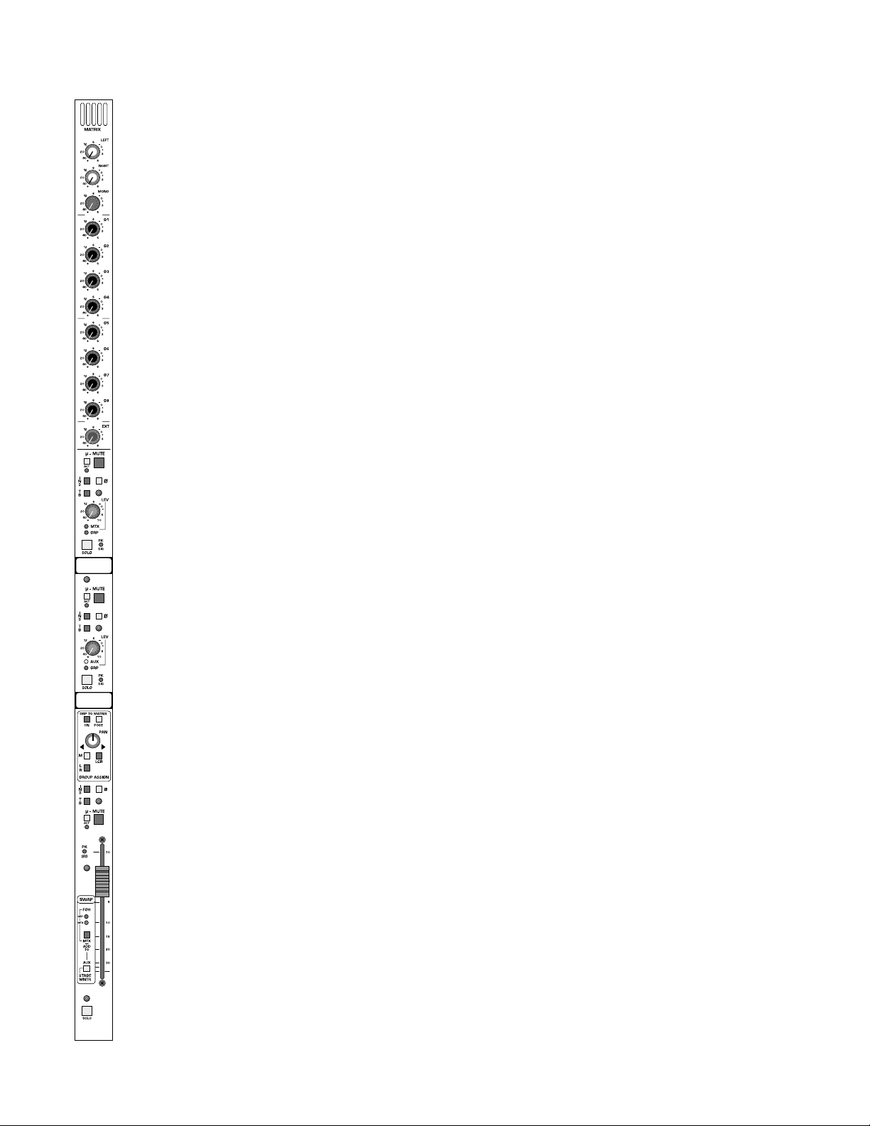
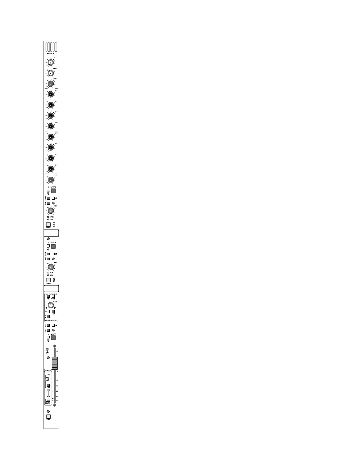
group output module—matrix, aux, group
mono-matrix features
This section is intended for use in Front of House operations to provide
a matrixed mix to dedicated locations.When the console is being used for
monitor mixing operations,this section can be used as a matrixed mix to
feed generic mixes to various stage locations. When teamed with an
external patch from an input module’s direct output connector to the
external input of the matrix module, a customized mix can be generated
for supporting artists such as horn or background vocal sections. This is
accomplished by mixing the artists individual microphone with up to 11
generic analog group mixes.
MATRIX OUTPUT CONNECTOR - XLR Balanced—on rear-panel.
INSERT SEND AND RETURN MATRIX CONNECTORS - SEPARATE
1/4” Balanced Send and Return connectors—on rear-panel.
EXTERNAL MATRIX INPUT CONNECTOR - XLR Balanced—on rearpanel.
left to matrix
Controls the amount of Left signal fed to the matrix output. Signal is
sourced pre or post fader as determined by a Pre/Post switch within the
master fader bay located next to Left/Right/Mono output faders.
right to matrix
Controls the amount of Right signal fed to the matrix output. Signal is
sourced pre or post fader as determined by a Pre/Post switch within the
master fader bay located next to Left/Right/Mono output faders.
mono to matrix
Controls the amount of Mono signal fed to the matrix output. Signal is
sourced pre or post fader as determined by a Pre/Post switch within the
master fader bay located next to Left/Right/Mono output faders.
group 1 to matrix
Controls the amount of Group 1 signal fed to the matrix output. Signal is
sourced pre or post lev el contr ol as determined b y Pr e/P ost switch located within each of the Group’s assignment sections.
group 2,3, 4, 5,6, 7, 8 to matrix
Same as Group 1 above f or each of the remaining groups.
Page 19
p. 19
group output module—matrix, aux, group
mono-matrix features
external-in signal-level to matrix
Controls level of signal present on XLR input connector on each matrix
module. It is this input that allows for customizing of backing artists generic mixes as this input can repr esent an artists individual microphone input.
UPPER CONTROL SECTION (Default Matrix Control)
illuminated mute-switch
Controls local mute function of this output section - Default is matrix
channel output. This switch illuminates red when this section is muted
(Regardless of source).
µ-mute switch
Sets and indicates microprocessor mute preset status. This illuminated
switch will show current µ-mute status preset as illuminated or not illuminated. It will show pre view next status as either blinking illuminated or
not illumination. Status of this µ-mute can be toggled on or off by depressing this momentary switch. This switch may also be dir ectl y accessed b y
an external sequencer if operating in external control mode.
The status of the µ-mute switch is stored in local memory for the current
mute scene, next, and last mute scene without the need to store any
changes to permanent memory. A snapshot of this switch in either active
or next (preview) mode may be stored to permanent memory if desired
from within the master microprocessor controller to any of the microprocessor storage locations in addition to the curr ent location.
This switch has no effect on the channels actual mute status until the master channel mute switch is activated within the master section of the console. The µ-mute may be loaded automatically b y the micropr ocessor system allowing sequenced (Master mute switch on at all times) or pre selected mute control (Master mute switch on onl y when mute preset is needed). If no microprocessor contr ol is required,the master mute switch ma y
be selected to manual operation,allowing this system to be preset and to
perform as any other manual mute preset.
µ-mute active-LED
Will illuminate RED when the µ-Mute system is commanding this section
to mute. The output master micro safe switch (located adjacent the master faders) determines whether or not the mute will actually occur. It is
possible to disable the µ-mutes for all outputs.
polarity-reverse switch
Reverses the polarity of the output signal.
Page 20

p. 20
group output module—matrix, aux, group
mono-matrix features
insert on-switch
Activates Insert return connector. Signal is always fed to balanced insert
send connector.
peak and signal-present LED
Dual color LED monitors the pre fader signal level and pr e/post fader clip
levels. This dynamic green intensity indicates pre fader signal level. The
LED will turn RED if the section gets within 3dB of clipping.
solo switch
Will illuminate when manually selected in one of the consoles many Solo
modes. Controls within the solo master section determine if this switch
will sample signal pre or post level control.
Additional switches will determine the operating characteristics of the
Solo system. These may be selected from within the master section to be
NORMAL (cumulative),LAST PRESSED (Only one switch will be on at a
time.Selecting the next solo switch will automatically cancel the last switch
selected) or MOMENTARY (Solo system on only while switch is held
down). This Solo switch will also Solo and illuminate automatically if the
VCA master group that the channel may be assigned to is put into SOLO.
The SOLO system displays selected channels on individual Solo Left and
Solo Right meters. The signal also appears on separate Headphone and
Monitor output channels. The solo signal may also be routed to the
Alternate A/B and C/D outputs within the master section.
talkback preset-switch
When selected will allow the Master T alkback Switch and system to access
this particular output.
output level-control (rotary pot)
Adjust the output level of this section,with a normal default as Matrix Out.
Page 21

p. 21
group output module—matrix, aux, group
mono-matrix features
Mtx master and GRP master LED indicators
Indicates the operation of this set of controls within this output section.
When the MTX MASTER LED (red) is illuminated, ALL of the controls
within this Upper Control Section will affect the matrix output. If the GRP
MASTER LED (Group) is illuminated (Only one LED will be illuminated),
ALL of the controls within this Upper Control Section will affect the
group output and feed to the Group Assignment section.
write-on strip
Will provide a number for this group output as well as providing a write
in area for the customer or a mounting surface for the customers masking tape labeling.
Page 22

p. 22
group output module—matrix, aux, group
aux master features
illuminated mute-switch
Controls local mute function of this output section - Default is matrix
channel output. This switch illuminates red when this section is muted
(Regardless of source).
µ-mute switch
Sets and indicates microprocessor mute preset status. This illuminated
switch will show current µ-mute status preset as illuminated or not illuminated. It will show pre view next status as either blinking illuminated or
not illumination. Status of this µ-mute can be toggled on or off by depressing this momentary switch. This switch may also be dir ectl y accessed b y
an external sequencer if operating in external control mode.
The status of the µ-mute switch is stored in local memory for the current
mute scene, next, and last mute scene without the need to store any
changes to permanent memory. A snapshot of this switch in either active
or next (preview) mode may be stored to permanent memory if desired
from within the master microprocessor controller to any of the microprocessor storage locations in addition to the curr ent location.
This switch has no effect on the channels actual mute status until the master channel mute switch is activated within the master section of the console. The µ-mute may be loaded automatically b y the micropr ocessor system allowing sequenced (Master mute switch on at all times) or pre selected mute control (Master mute switch on onl y when mute preset is needed). If no microprocessor contr ol is required,the master mute switch ma y
be selected to manual operation,allowing this system to be preset and to
perform as any other manual mute preset.
µ-mute active-LED
Will illuminate RED when the µ-Mute system is commanding this section
to mute. The output master micro safe switch (located adjacent the master faders) determines whether or not the mute will actually occur. It is
possible to disable the µ-mutes for all outputs.
polarity-reverse switch
Reverses the polarity of the output signal.
insert on-switch
Activates Insert return connector. Signal is always fed to balanced insert
send connector.
peak and signal-present LED
Dual color LED monitors the pre fader signal level and pr e/post fader clip
levels. This dynamic green intensity indicates pre fader signal level. The
LED will turn RED if the section gets within 3dB of clipping.
Page 23

p. 23
group output module—matrix, aux, group
aux master features
solo switch
Will illuminate when manually selected in one of the consoles many Solo
modes. Controls within the master section determine if this switch will
sample signal pre or post level control.
Additional switches will determine the operating characteristics of the
Solo system. These may be selected from within the master section to be
NORMAL (cumulative),LAST PRESSED (Only one switch will be on at a
time.Selecting the next solo switch will automatically cancel the last switch
selected) or MOMENTARY (Solo system on only while switch is held
down). This Solo switch will also Solo and illuminate automatically if the
VCA master group that the channel may be assigned to is put into SOLO.
The SOLO system displays selected channels on individual Solo Left and
Solo Right meters. The signal also appears on separate Headphone and
Monitor output channels. The solo signal may also be routed to the
Alternate A/B and C/D outputs within the master section.
talkback preset-switch
When selected will allow the Master T alkback Switch and system to access
this particular output.
output level-control (rotary pot)
Adjust the output level of this section,with a normal default as Aux Out
AUX-master and GRP-master LED indicators
Indicates the operation of this set of controls within this middle output
section. When the AUX MASTER LED (yellow) is illuminated,ALL of the
controls within this Middle Control Section will aff ect the AUX output. If
the GRP MASTER LED (green) is illuminated (Only one will be illuminated),ALL of the controls within this Upper Control Section will affect the
group output and feed to the Group Assignment section.
write-on strip
Will provide a number for this group output as well as providing a write
in area for the customer or a mounting surface for the customers masking tape labeling.
Page 24

p. 24
group output module—matrix, aux, group
group-assignment features
This section always receives its signal from any output block acting as the
Group Master Output.This may be the default Lower fader section or the
mid or upper control sections as indicated by LED status indicator located within the individual output block sections. The swap contr ols near the
fader define the output block section.Only one section can be designated
as the Group Output section at one time.
matrix post-switch
Changes the group to matrix source fr om the normal pre group le vel location to a post level send. This switch will affect the group send to all 12
matrix modules.
group-to-matrix on-switch
Activates the group send signal to the matrix section of the console. This
switch will affect the group send to all 12 matrix modules.
mono-assignment switch
Direct assignment of post group level control to mono mix bus.
left-/right-assignment switch
Assigns post pan pot signals to left and right mix buses.
LCR switch
Reconfigures pan pot to LCR operation,requires the M and LR assignment
switches to also be selected.
pan control
Adjust panoramic image between the Left and Right output buses When
LCR is selected, provides true LCR panning between Left and Center
and Center and Right buses.
Page 25

p. 25
group output module—matrix, aux, group
group-master features
illuminated mute-switch
Controls local mute function of this output section - Default as matrix
channel output. This switch illuminates red when this section is muted
(Regardless of source).
µ-mute switch
Sets and indicates microprocessor mute preset status. This illuminated
switch will show current µ mute status preset as illuminated or not illuminated. It will show pre view next status as either blinking illuminated or
not illumination. Status of this µ mute can be toggled on or off by depressing this momentary switch. This switch may also be dir ectl y accessed b y
an external sequencer if operating in external control mode.
The status of the µ mute switch is stor ed in local memory for the current
mute scene, next, and last mute scene without the need to store any
changes to permanent memory. A snapshot of this switch in either active
or next (preview) mode may be stored to permanent memory if desired
from within the master microprocessor controller to any of the microprocessor storage locations in addition to the curr ent location.
This switch has no effect on the channels actual mute status until the master channel mute switch is activated within the master section of the console. The µ mute ma y be loaded automatically by the micr opr ocessor system allowing sequenced (Master mute switch on at all times) or pre selected mute control (Master mute switch on onl y when mute preset is needed). If no microprocessor contr ol is required,the master mute switch ma y
be selected to manual operation,allowing this system to be preset and to
perform as any other manual mute preset.
µ-mute active-LED
Will illuminate RED when the µ-Mute system is commanding this section
to mute. The output master micro safe switch (located adjacent the master faders) determines whether or not the mute will actually occur. It is
possible to disable the µ-mutes for all outputs.
polarity-reverse switch
Reverses the polarity of the output signal.
insert on-switch
Activates Insert return connector. Signal is always fed to balanced insert
send connector.
peak and signal-present LED
Dual color LED monitors the pre fader signal level and pr e/post fader clip
levels. This dynamic green intensity indicates pre fader signal level. The
LED will turn RED if the section gets within 3dB of clipping.
Page 26

p. 26
group output module—matrix, aux, group
group-master features
solo switch
Will illuminate when manually selected in one of the consoles many Solo
modes. Controls within the master section determine if this switch will
sample signal pre or post level control.
Additional switches will determine the operating characteristics of the
Solo system. These may be selected from within the master section to be
NORMAL (cumulative),LASTPRESSED (Only one switch will be on at a
time.Selecting the next solo switch will automatically cancel the last switch
selected) or MOMENTARY (Solo system on only while switch is held
down). This Solo switch will also Solo and illuminate automatically if the
VCA master group that the channel may be assigned to is put into SOLO.
The SOLO system displays selected channels on individual Solo Left and
Solo Right meters. The signal also appears on separate Headphone and
Monitor output channels. The solo signal may also be routed to the
Alternate A/B and C/D outputs within the master section.
talkback preset-switch
When selected will allow the Master T alkback Switch and system to access
this particular output.
output level-control (100mm fader)
Adjust the output level of this section,with a normal default as Group Out
Page 27

module swap features
mode switch (recessed)
Controls the assignment of output functions between the three output
blocks. This switch toggles between FOH(Front of House) and MONITOR(AUX) operation of the lower fader area. When Monitor (Aux) is
selected, the middle control section of the module takes over Group
Operation.
MTX switch (recessed)
The operation of this switch is determined by the above MODE switch.
When in FOH Mode, and this MTX switch is NOT depressed,this module
is operating in default mode. Group output is controlled by the lower block
with the Status LED indicating FOH SUB GRP. The Mid section LED status
indicator indicates and operates as AUX MASTER, and the Upper block section LED status indicator indicates and operates as MATRIX MASTER.
When in FOH Mode, and this MTX switch IS depressed, this lower block
and all of its functions will operate as the Matrix Control Section with the
LED status indicator showing FOH MATRIX OUT. The Mid section LED
status indicator still indicates and operates as AUX MASTER, and the Upper
block section LED status indicator now indicates and operates as a GR OUP
MASTER.
When in STAGE MONITOR MODE, this lower block and all of its functions will operate as the MONIT OR (AUX) Control Section with the LED
status indicator showing MONIT OR OUT. The Mid section LED status indicator indicates and operates as GROUP MASTER, and the Upper block section LED status indicator indicates and operates as a AUX MASTER.
When in STAGE MONITOR MODE and the MTX switch is depressed,a
post matrix level signal is fed to the MONITOR (AUX) mix bus. An internal jumper allows the matrix to be sourced pre fader if desir ed. This allows
generic mixes such as drums to be able to be mixed with the primary monitor outputs. When in this mode, only the MTX switch itself will illuminate,
while the primary ST AGE MONITOR MODE LED will remain illuminated.
FOH group LED
Indicated that the lower fader block is controlling the ANALOG SUB
GROUP output of this module.
FOH matrix LED
Indicated that the lower fader block is controlling the MATRIX output of
this module.
STAGE MONITOR LED
Indicated that the lower fader block is controlling the MONITOR (AUX)
output of this module.
write-on strip
Will provide a number for this group output as well as providing a write
in area for the customer or a mounting surface for the customers masking tape labeling.
p. 27
group output module—matrix, aux, group
Page 28

group output module—matrix, aux, group
group rear-panel connectors
Always as labeled - Not affected by mode switch.
MATRIX OUTPUT CONNECTOR - XLR Balanced
INSERT SEND AND RETURN MATRIX CONNECTORS - SEPARATE
1/4” Balanced Send and Return connectors.
EXTERNAL MATRIX INPUT CONNECTOR - XLR Balanced
AUX (MONITOR) OUTPUT CONNECTOR - XLR Balanced
INSERT SEND AND RETURN Aux CONNECTORS - SEPARATE 1/4”
Balanced Send and Return connectors.
ANALOG GROUP OUTPUT CONNECTOR - XLR Balanced
INSERT SEND AND RETURN GROUP CONNECTORS - SEPARATE
1/4” Balanced Send and Return connectors.
p. 28
Page 29

p. 29
vca masters
VCA MASTER
FADER BAY MODULE FUNCTIONS
illuminated mute-switches (12)
Controls mutes of input channels assigned to the particular VCA Group.
Internal jumper select between a input channel mute function (default) or
as a VCA channel pull down.
100mm faders (12)
Very high quality conductive plastic fader are used in a 6 panel space area
with double spacing (2 faders per standard channel width) A master DC
voltage is generated and controlled by each VCA master section to control each input channel assigned to the particular VCA channel.
solo switches (12)
These will Solo ALL channels assigned to that VCA Master. Input channels
that are assigned to the corresponding Master will illuminate as if individually soloed when the VCA Master Solo switch is selected.
Page 30

p. 30
group output module
—matrix, aux, group
LEFT/RIGHT/MONO
MASTER FADER BAY MODULE FUNCTIONS
illuminated mute-switches (3)
Controls mutes of main outputs.
output mute safe switch
Disables the Left, Right, and Mono Mute switches to prevent accidental
activation during a performance.
100mm faders
3 Individual Left,Right, and Mono (Center) high quality conductive plastic
faders are used.
left,right and mono peak and signal-present LEDS
Dual color LED monitors the pre fader signal levels. Signal present indication is dynamic and varies with pre fader signal level. If signal approached
3dB of causing distortion,the LED will turn RED.
left/right/mono to matrix on-switch
Activates the Left/Right/Mono send signal to the matrix section of the console. This switch will affect the Left/Right/Mono send to all 12 matrix modules.
matrix-post switch
Changes the individual left/right/mono to matrix source from the normal
pre level location to a post level send. This switch will affect the
left/right/mono send to all 12 matrix modules (8 mono,4 stereo).
mono to sum-output switch
Will assign the post fader Mono (Center) signal to the SUM OUTPUT
XLR rear panel Connector.
L-R to sum-output switch
Will assign the post fader left and right signals to the SUM OUTPUT XLR
rear panel connector.
L-R to mono switch
Assigns the post (Internal Jumper for Pre) left and right signal to the Mono
Mix Bus.
Page 31

input fader block
LOWER MODULE CONSTRUCTION
act LED (µ-mute)
This red LED lites whenever a Mute command is issued from the Micro.
This can be from any of the Sequenced or Manual Mute Scenes or fr om a
received MIDI Note command.Whether or not the channel responds to
that mute command is determined by the status of two SAFE switches:the
global Input Micro Safe switch (near master faders),or the channel Mute
Safe switch.
mute safe
This switch "safes" the channel from external mute commands (micro,
VCA,SIP).By default,the VCA and Solo-In-Place (SIP) mute commands ar e
safed, but there are two jumpers located on each fader circuit board to
exclude each of them.The micro mute commands (Man Mute, Seq Scene
or MIDI mutes) are always affected by the safe.
act LED (VCA)
This red LED lights whenever a mute command is coming from an
assigned VCA. Each VC A Master has an associated Mute switch. When
depressed,any channels assigned to that VCA Master will go to a fader fulldown condition (max attenuation),and the channel mute will be activated.
A jumper in the VCA Master fader block can defeat the mute function;in
that case, the channels still go to fader full-down, but the channel mute is
not activated.
VCA assign
These 12 lit switches are used to assign a channel to any of the 12 VCA
Masters. The channel gain is controlled by the sum of the voltages of the
local fader and any of the assigned VCA Masters.The VCA control circuitry is designed so that even if a channel is assigned to all 12 masters, and
those masters are all at +10dB boost (total of +120dB theoretical gain!),
the local fader (or any Master fader) ,when pulled down,has enough electrical over-travel to fully attenuate the channel.Furthermore, the control
voltage is electrically limited to a maximum of +20dB gain to prevent
excessive channel boost.
p. 31
Page 32

p. 32
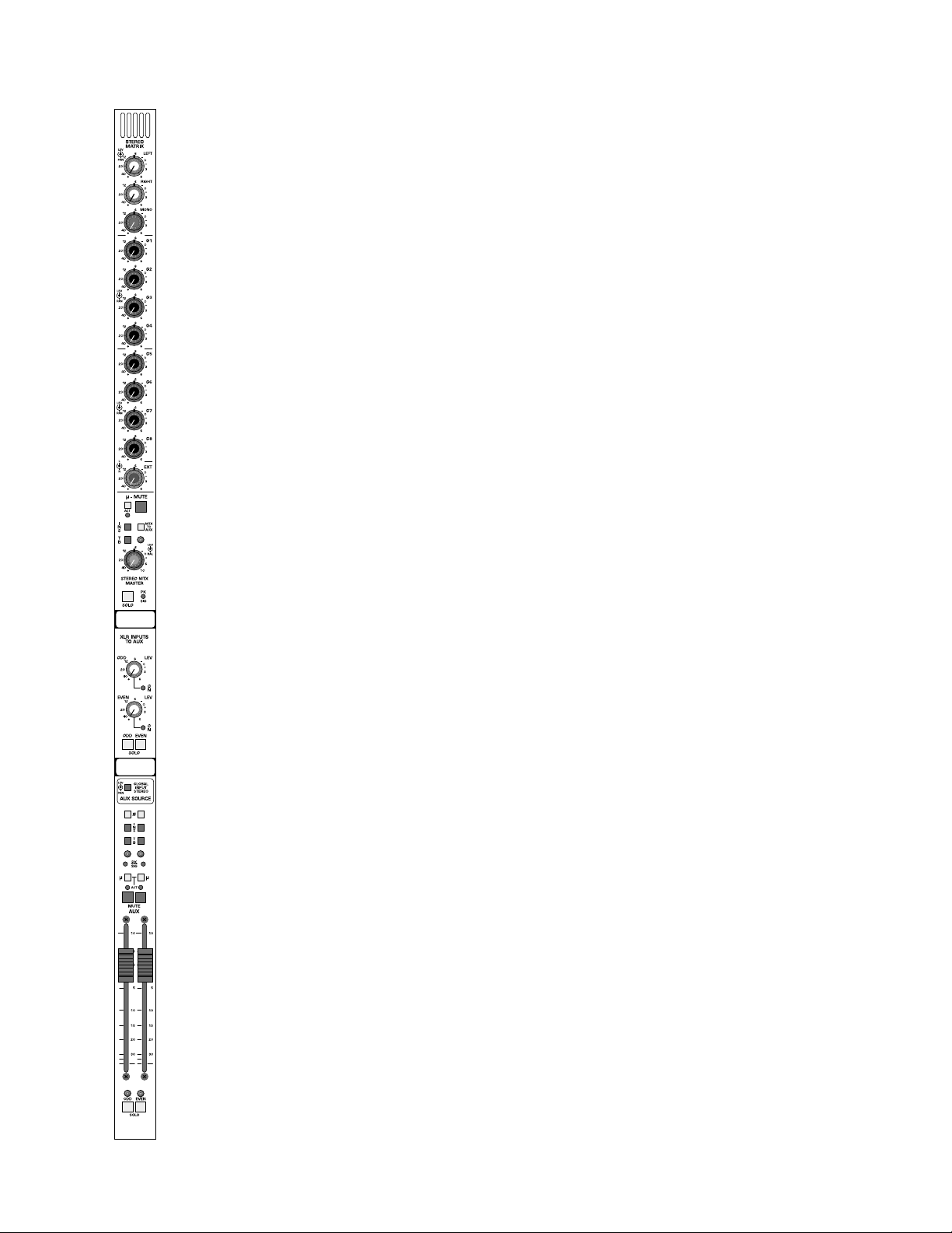
stereo matrix / aux out module
stereo-matrix features
This section is intended for use in Front of House operations to provide
a matrixed stereo mix to dedicated locations. When the console is being
used for monitor mixing operations,this section can be used as a matrixed
stereo mix to feed generic mixes to various stage locations.When teamed
with an external patch from an input modules direct output connectors to
the external input of the matrix module,a customized mix can be generated for supporting artists such as horn or background vocal sections.This
is accomplished by mixing the artists individual microphone input with up
to 11 generic analog group mixes.
MATRIX OUTPUT CONNECTORS - XLR Balanced
INSERT SEND AND RETURN MATRIX CONNECTORS - SEPARATE
left and right 1/4” Balanced Send and Return connectors.
EXTERNAL MATRIX INPUT CONNECTORS - Separate left and Right
XLR Balanced inputs.
left to matrix
Controls the amount of Left signal fed to the matrix output. Signal is
sourced pre or post fader as determined by a Pre/Post switch within the
master fader bay located next to Left/Right/Mono output faders. This signal may be repositioned an ywhere in the stereo image using a standar d Pan
Control.
right to matrix
Controls the amount of Right signal fed to the matrix output. Signal is
sourced pre or post fader as determined by a Pre/Post switch within the
master fader bay located next to Left/Right/Mono output faders. This signal may be repositioned an ywhere in the stereo image using a standar d Pan
Control.
mono to matrix
Controls the amount of Mono signal fed to the matrix output. Signal is
sourced pre or post fader as determined by a Pre/Post switch within the
master fader bay located next to Left/Right/Mono output faders. This signal may be positioned anywhere in the stereo image using a standard Pan
Control.
group 1 to matrix
Controls the amount of Group 1 signal fed to the matrix output.Signal is
sourced pre or post level as determined by the Pre/Post switch located
within each Groups assignment section. This signal may be repositioned
anywhere in the stereo image using a standard Pan Control.
group 2,3, 4, 5,6, 7, 8 to matrix
Same as Group 1 above f or each of the remaining groups.
Page 33
p. 33
stereo matrix / aux out module
stereo-matrix features
external-in left and right signal-level to matrix
Dual Concentric level control pair with center controlling left XLR line
input to left matrix output and the outside controlling the right XLR line
input to the right matrix output. It is this set of inputs that allows for customizing of backing artists generic mixes,as these inputs can represent an
artists microphone inputs.
illuminated mute-switch
Controls local mute function of this stereo matrix output.This switch illuminates red when this section is muted (Regardless of source).
µ-mute switch
Sets and indicates microprocessor mute preset status of this stereo
matrix output. This illuminated switch will show current µ-mute status
preset as illuminated or not illuminated. It will show preview next status
as either blinking illuminated or not illumination. Status of this µ-mute can
be toggled on or off by depressing this momentary switch. This switch
may also be directly accessed by an external sequencer if operating in
external control mode.
The status of the µ-mute switch is stored in local memory for the current
mute scene, next, and last mute scene without the need to store any
changes to permanent memory. A snapshot of this switch in either active
or next (preview) mode may be stored to permanent memory if desired
from within the master microprocessor controller to any of the microprocessor storage locations in addition to the curr ent location.
This switch has no effect on the stereo matrixes actual mute status until
the master output mute switch is activated within the master section of
the console. The µ-mute may be loaded automatically by the microprocessor system allowing sequenced (Master mute switch on at all times)
or pre selected mute control (Master mute switch on only when mute
preset is needed). If no microprocessor control is required, the master
mute switch may be selected to man ual operation,allowing this system to
be preset and to perform as any other manual mute preset.
µ-mute active-LED
Will illuminate RED when the µ-Mute system is commanding this section
to mute. The output master micro safe switch (located adjacent the master faders) determines whether or not the mute will actually occur. It is
possible to disable the µ-mutes for all outputs.
Page 34

p. 34
stereo matrix / aux out module
stereo-matrix features
mtx to aux
When this switch is depressed,a post stereo matrix level signal is fed to
the modules left and right Aux (Monitor) mix buses. An internal jumper
allows the matrix to be sourced pre fader if desired. This allows generic
mixes such as drums to be able to be mixed with the primary aux monitor outputs.
insert-on switch
Activates the stereo Insert return connector. Signal is always fed to the
stereo balanced insert send connector.
peak and signal-present LED
A single dual color LED monitors pre level control stereo signal levels.
Dynamic level indications are b y varying the intensity of the green element
of the dual color LED.The LED will turn RED if signal approaches 3dB of
causing clipping of the left or right outputs.
stereo matrix solo-switch
Will illuminate when manually selected in one of the consoles many Solo
modes. Controls within the master section determines if this switch will
sample signal pre or post level control.
Additional switches will determine the operating characteristics of the
Solo system. These may be selected from within the master section to be
NORMAL (cumulative),LAST PRESSED (Only one switch will be on at a
time.Selecting the next solo switch will automatically cancel the last switch
selected) or MOMENTARY (Solo system on only while switch is held
down).
talkback preset-switch
When selected will allow the Master T alkback Switch and system to access
the associated Stereo output matrix.
stereo matrix output-level control
Adjust the left and right output levels of this section.
stereo matrix output-balance control
Adjusts the balance between the left and right outputs.
write-on strip
Will provide a number for this group output as well as providing a write
in area for the customer or a mounting surface for the customers masking tape labeling.
Page 35

stereo matrix / aux out module
dual-aux output features
This section controls aux outputs number 9 through 16. It is intended to
operate as individual aux outputs, or when the module’s stereo mode
switch is depressed,as a stereo output. In stereo configuration,this output par may be used to generate dedicated broadcast or cart machine
feeds,or when used as a monitor console, to generate stereo wedge or
“In the Ear” monitor feeds.
XLR-input odd-level control with push-on/push-off switch
Controls the contents of the associated left XLR aux bus input level into
the associated (odd numbered) mix bus. This may be used to return
effects returns into the aux system when used for “In the Ear” type monitoring systems, or simply to expand the number of inputs available.
Pushing this control will turn the input source on and off and is indicated
by a status LED indicator located next to the control.
XLR-input even-level control with push-on/push-off switch
Controls the contents of the associated right XLR aux bus input level into
the associated (odd numbered) mix bus. This may be used to return
effects returns into the aux system when used for “In the Ear” type monitoring systems, or simply to expand the number of inputs available.
Pushing this control will turn the input source on and off and is indicated
by a status LED indicator located next to the control.
solo-left and solo-right
Will individually ,or when both are depressed as a ster eo pair,monitor the
contents of the XLR INPUT returns.
global-input stereo switch
Reconfigures the associated input modules dual concentric aux controls
from dual mono mode to a level and pan pot configuration to enable simple construction of stereo mixes.
polarity-reverse switch
(one odd channel,one even channel)
Reverses the polarity of the aux output signals.
insert-on switch
(one odd channel,one even channel)
Activates Insert return connector. Signal is always fed to balanced insert
send connector.
peak and signal-present LED
(one odd channel,one even channel)
A single dual color LED monitors pre fader signal levels. Dynamic level
indications are by varying the intensity of the green element of the dual
color LED. The LED will turn RED if signal approaches 3dB of clipping of
the left or right outputs.
p. 35
Page 36

p. 36
stereo matrix / aux out module
dual-aux output features
talkback preset-switch
(one odd channel,one even channel)
When selected will allow the Master T alkback Switch and system to access
this particular output.
µ-mute switch
Sets and indicates microprocessor mute preset status. This illuminated
switch will show current µ mute status preset as illuminated or not illuminated. It will show pre view next status as either blinking illuminated or
not illumination. Status of this µ mute can be toggled on or off by depressing this momentary switch. This switch may also be dir ectl y accessed b y
an external sequencer if operating in external control mode.
The status of the µ mute switch is stor ed in local memory for the current
mute scene, next, and last mute scene without the need to store any
changes to permanent memory. A snapshot of this switch in either active
or next (preview) mode may be stored to permanent memory if desired
from within the master microprocessor controller to any of the microprocessor storage locations in addition to the curr ent location.
This switch has no effect on the channels actual mute status until the master channel mute switch is activated within the master section of the console. The µ mute ma y be loaded automatically by the micr opr ocessor system allowing sequenced (Master mute switch on at all times) or pre selected mute control (Master mute switch on onl y when mute preset is needed). If no microprocessor contr ol is required,the master mute switch ma y
be selected to manual operation,allowing this system to be preset and to
perform as any other manual mute preset.
µ-mute active-LED
Will illuminate RED when the µ-Mute system is commanding this section
to mute. The output master micro safe switch (located adjacent the master faders) determines whether or not the mute will actually occur. It is
possible to disable the µ-mutes for all outputs.
illuminated mute-switch
Controls local mute function of this output. This switch illuminates red
when this section is muted (Regardless of source).
100mm output fader
(one per odd channel,one per even channel)
High quality fader per each aux output.
Page 37

p. 37
stereo matrix / aux out module
dual-aux output features
solo switch
Will illuminate when manually selected in one of the consoles many Solo
modes. Controls within the master section determine if this switch will
sample signal pre or post level control.
Additional switches will determine the operating characteristics of the
Solo system. These may be selected from within the master section to be
NORMAL (cumulative),LAST PRESSED (Only one switch will be on at a
time.Selecting the next solo switch will automatically cancel the last switch
selected) or MOMENTARY (Solo system on only while switch is held
down). This Solo switch will also Solo and illuminate automatically if the
VCA master group that the channel may be assigned to is put into SOLO.
The SOLO system displays selected channels on individual Solo Left and
Solo Right meters. The signal also appears on separate Headphone and
Monitor output channels. The solo signal may also be routed to the
Alternate A/B and C/D outputs within the master section.
write-on strip
Will provide a number for this group output as well as providing a write
in area for the customer or a mounting surface for the customers masking tape labeling.
Page 38

p. 38
master modules—M1, M2
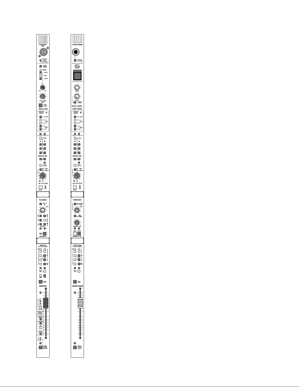
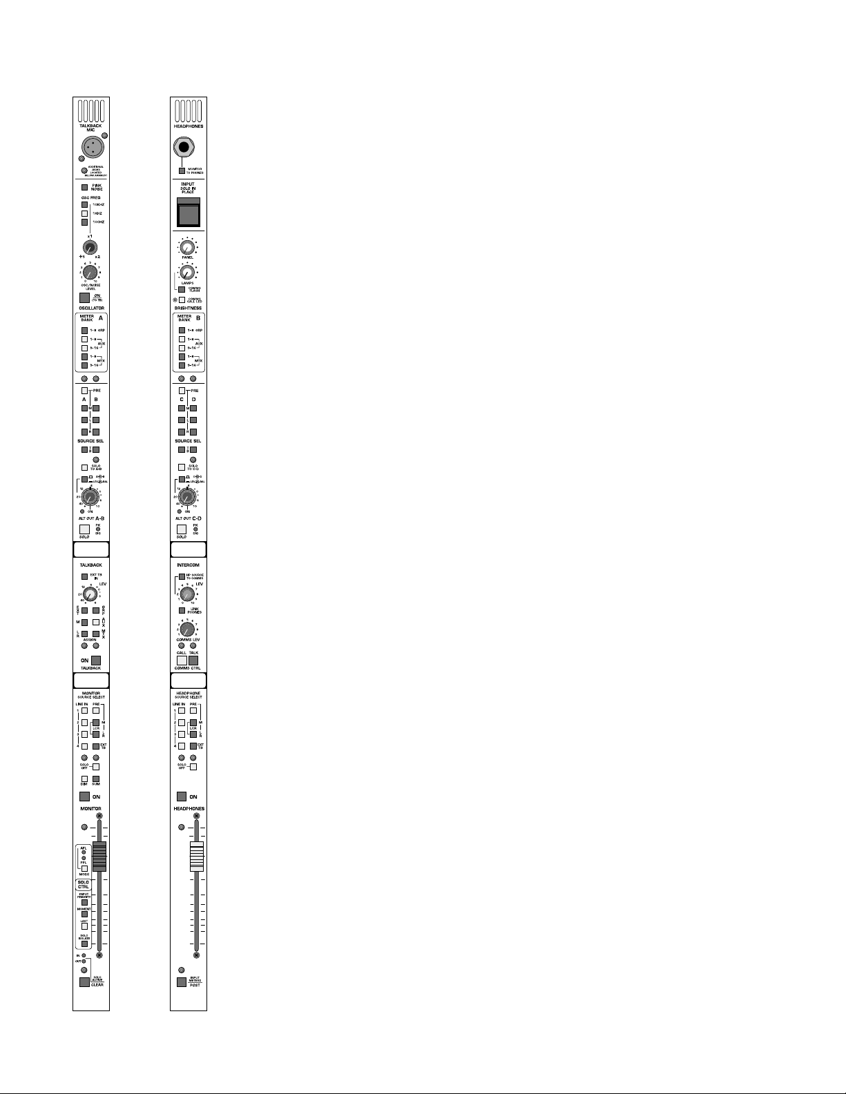
oscillator features
pink-noise switch
When depressed will generate Pink Noise in place of a sine wav e signal as
the signal generator output.
10kHz,1kHz,100Hz switches
Selects the center point of the oscillator frequency control pot.
frequency control
Will adjust frequency output of the section over a 10 to 1 range with the
center frequency chosen with the above switches.
oscillator level-control
Controls amplitude of signal level output of the oscillator section.
oscillator on-switch
Turns on the oscillator and assigns signals through the talkback section of
the console. The oscillator does not have a dedicated output as it can be
assigned to every output of the console through the talkback system.
Page 39

p. 39
master modules—M1, M2
meter-view features
meters-A/meters-B switch bank
(One set per module - Left master module switch bank controls left 8
meters,Right master module switch bank controls right 8 meters)
GROUP 1-8
AUX 1-8
AUX 9-16
MTX 1-8
MTX 9-16
Interlocking switches selects the display function of the left or right meter
banks. In addition to illumination of these switches, an indicator in the
meter area shows what functions the 8 left and 8 right meters are displaying.
Page 40

p. 40
master modules—M1, M2
alternate output features
Alternate output A-B are located on the left master module and Alternate
output C-D are located on the right master module. Controls provided
on the left and right module alternate outputs are identical. This section is
intended for miscellaneous signal outputs including dressing room feeds,
broadcast production monitor feeds, sub output feeds, delay speaker
stacks, back of stage feeds, etc. Each module contains the following controls:
source-pre
Selects between the default post fader signal level and a pre fader level.
This switch will affect both the odd and even signal sources.
left-select switch
Selects the Left main signal. Separate switches to A (C) and B (D) outputs.
This allows for generation of summed and reversed signal outputs.
right-select switch
Selects the Right main signal. Separate switches to A (C) and B (D) outputs. This allows for generation of summed and reversed signal outputs.
mono-select switch
Selects the Mono main signal. Separate switches to A (C) and B (D) outputs. This allows for generation of summed LCR and reversed image signal outputs.
solo to A-B (C-D)
Puts the contents of the Solo bus on outputs A-B and/or C-D.
stereo switch
Reconfigures the dual concentric level control fro dual mono function to
Stereo level and Balance control.
peak and signal-present indicator
Monitors signal levels of the pair of outputs. Green signal present LED
indicator is dynamic and varies in intensity . Should any signal level approach
3dB of clipping,the red Peak LED indicator will illuminate.
Page 41

p. 41
master modules—M1, M2
alternate output features
solo switch
Will illuminate when manually selected in one of the consoles many Solo
modes. Controls within the master section determine if this switch will
sample signal pre or post level control.
The SOLO system is designed that if the Alternate output is soloed,it will
display its contents on the Solo meters,but it will not feed Solo signal to
the Alternate output section, avoiding a potential source of a feedback
loop.
write-on strip
Provides an area to label the alternate outputs usage.
Page 42

p. 42
master modules—M1, M2
talkback master features
group talkback master-switch
Allows talkback to all group outputs that ha ve their talkback pr eset switch
selected when the MASTER Talkback switch is depressed. No communications is permitted to Group Outputs unless this master switch is
depressed.
aux talkback master-switch
Allows talkback to all Aux outputs that have their talkback preset switch
selected when the MASTER Talkback switch is depressed.. No communications is permitted to Aux Outputs unless this master switch is
depressed.
matrix talkback master-switch
Allows talkback to all Matrix outputs that hav e their talkback preset switch
selected when the MASTER Talkback switch is depressed.. No communications is permitted to Matrix Outputs unless this master switch is
depressed.
mono talkback master-switch
Allows talkback to the Mono Output when the master Talkback switch is
activated.
left/right talkback master-switch
Allows talkback to the Left and Right Outputs when the master Talkback
switch is activated.
talkback out
Allows talkback to a rear panel XLR connector when the master Talkback
switch is activated.
talkback level-control
Adjusts the overall volume of the talkback system.
external talkback-in assignment
Allows the contents of the XLR Talkback in connector to have access to
all of the consoles talkback systems. This switch activates the Talkback system for this signal source only without the need to depress the master
Talkback switch.
Page 43

p. 43
master modules—M1, M2
intercom interconnect features
The console is designed to interconnect with a ClearCom compatible
intercom system. Three-pin male and female XLR’s are located on the
console rear -panel for inter com hookup and loop-thru.A separate four pin
XLR connector is located under the arm rest for connection to a standard
intercom headset.
console-to-intercom level and switch
Controls the amount of console signal fed to the intercom system as
selected by the source selection switches located within the headphone
system.
link headphone/intercom switch
Allows both intercom and console signals to be monitored on the high
quality system headphones AND the intercom headset.
comms level
This control determines the level of the intercom signal in the COMMS
headset or,if the link phones switch is depressed,the amount of intercom
signal mixed into the console headphones.
call button
Sends an intercom call command when pressed,and will also illuminate to
indicate a call signal is being received.The operator also has the option,by
way of the COMMS FLASHswitch, of having the console Little-Lites flash
upon receiving a call signal. Additionally,hi-intensity blue LEDs in the meter
bridge will flash when a call signal is received.Their brightness is controlled
by the COMMSCALL LED switch in the upper section of the module.
Page 44

p. 44
master modules—M1, M2
monitor output features
MONIT OR OUTPUT CONNECTORS - XLR balanced line level outputs
on the rear panel plus 1/4” headphone connector under the arm rest area
with a hinged cover pre v enting confusing with the r egular headphone system.
line 1 input-switch
Monitor source of XLR Stereo Pair of balanced line level inputs.
line 2 input-switch
Monitor source of XLR Stereo Pair of Balanced line level inputs.
line 3 input-switch
Monitor source of 1/4” Balanced/Unbalanced line level inputs in mono or
stereo. If only a single connector is plugged in,signal is monitored in mono.
line 4 input-switch
Monitor source of 1/4” Balanced/Unbalanced line level inputs in mono or
stereo. If only a single connector is plugged in,signal is monitored in mono.
mono-output switch
Monitors mono output signal.
left/right output switch
Monitors left and right output signals.
LCR output monitoring
When both Left/Right and Mono switches are depressed,a LCR signal mix
can be monitored on a pair of monitor outputs.
external talkback-in
Allows direct monitoring of the external talkback input (Closed loop system).
Page 45
p. 45
master modules—M1, M2
monitor output features
sum
Combines the Left and Right signals into a summed mono signal with the
same signal appearing on the left and right output connectors and in headphones.
dim
Drops the XLR signal output level by 20db while depressed.
100mm fader level-control
Adjust output level of the monitor output.
solo defeat
Normally the Solo system will override any monitor switches that have
been selected. When the Solo Defeat switch is selected,no solo signal will
appear on this output.
on-switch
Turns on the output of the monitor section to both rear panel XLR connectors and to monitor headphone outputs.
foot pedal monitor-level control
A rear panel 1/4” jack is provided to allo w monitor le vel to be controlled
by a foot pedal.
Page 46
p. 46
master modules—M1, M2
headphone output features
HEADPHONE OUTPUT CONNECT ORS - 1/4” headphone connector
under the arm rest area as well as on the top module panel.
HEADPHONE INSERT CONNECTORS - Separate left and right insert
send and return connectors for the purpose of inserting external delay
devices. In addition, as these points are located after the master headphone level control,the insert send can be used to feed an external higher powered amplifier.
line 1 input-switch
Monitor source of XLR Stereo Pair of balanced line level inputs to headphones.
line 2 input-switch
Monitor source of XLR Stereo Pair of Balanced line level inputs to headphones.
line 3 input-switch
Monitor source of 1/4” Balanced/Unbalanced line level inputs in mono or
stereo to headphones. If only a single connector is plugged in, signal is
monitored in mono.
line 4 input-switch
Monitor source of 1/4” Balanced/Unbalanced line level inputs in mono or
stereo to headphones. If only a single connector is plugged in, signal is
monitored in mono.
mono-output switch
Monitors mono output signal to headphones.
left-/right-output switch
Monitors left and right output signals to headphones.
LCR output-monitoring
When both Left/Right and Mono switches are depressed,a LCR signal mix
can be monitored on headphones.
external talkback-in
Allows direct monitoring of the external talkback input (closed loop sys-
tem) on headphones.
Page 47

p. 47
master modules—M1, M2
headphone output features
solo defeat
Normally the Solo system will override any monitor switches that have
been selected. When the Solo Defeat switch is selected,no solo signal will
appear on headphones.
on-switch
Turns on the headphone output. The prevents leakage of headphone signal to noise sensitive rooms by being able to turn off headphones before
they are remo ved.
100mm headphone level-control
Adjusts the level of the consoles headphone output lev el. When the intercom and console system headphone systems are linked,the level controls
remain independent for their fused usage. Intercom level control always
controls intercom le vel and headphone lev el controls consoles headphone
monitor level regardless of the headphone type being used.
Page 48

p. 48
master modules—M1, M2
solo system features
solo-clear switch
When any input or output solo switch is active, depressing the SOLO
CLEAR switch will cancel all soloed channels. When in Input Priority
mode,this switch will only cancel only input channel solo functions.
solo-select switch
Will select operation of the solo system to monitor either pre fader signals or post fader/post pan pot signals. Mono signals are monitored n
mono,stereo signals are monitored in stereo .This switch may be changed
while in use.
input-priority switch
When in this mode,soloing an input channel will take priority over an output channel only while the input solo switches are depressed. When the
input channel is no longer selected,the console goes back to the previous
output solo condition. When in this mode, the first press of the SOLO
CLEAR switch will clear input channels only; a second, longer press will
clear the output solos.
solo-momentary switch
In this mode,solo switches are active only while they are held down.
last-pressed switch
T ak es the console out of its normal cumulative mode and puts it into LAST
PRESSED mode. When a solo switch is already depressed,depressing the
second solo switch will cancel the previous solo switch.When a VCA solo
is activated,this is treated as a single solo switch and all associated channels are monitored.
solo-isolate switch
When used with consoles linked together,will isolate the solo output of
the slaved console from the master console. This allows for independent
monitoring of linked consoles when desired.
solo active in and out LED’s
Will illuminate if any input or output solo switch is selected and active.
input meter post-switch
Selects operation for all input channel eight-segment metering between
the input pre fader monitor point to a post fader monitor point.The selection between pre and post fader meter selection is uniform across the
console.
Page 49

p. 49
Page 50
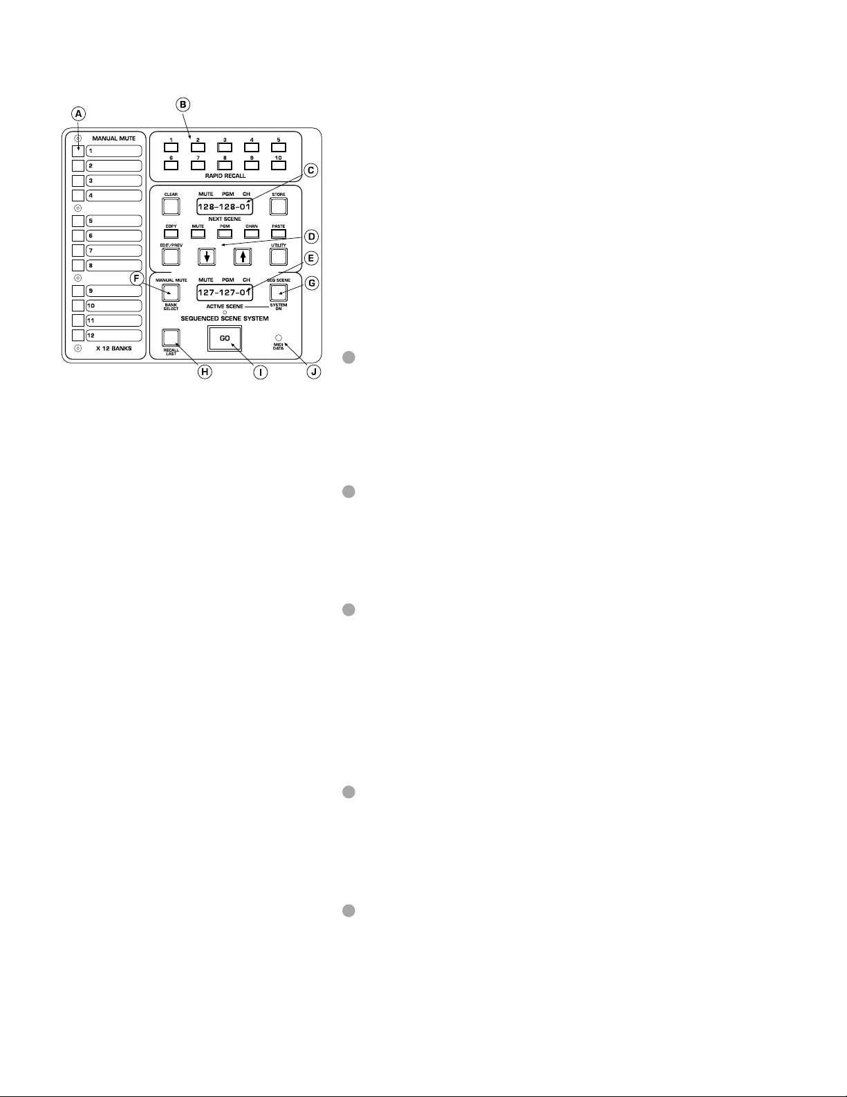
p. 50
micro mute system
micro panel features
The V -12 is equipped with a micr oprocessor based muting and contr ol system. This system allows the operator to control the channel and output
mutes of the console using pre-set manual mute scenes,pre-programmed
sequenced scenes or through MIDI based external sequencers. The V-12
micro system can also be configured to send MIDI Show Control commands. With these commands, a compatible external sequencer can be
used to control various aspects of a show by controlling different pieces
of outboard gear.The system can be set up to the operator’s preference
by using the comprehensive utility functions. MIDI status, Mute Scene
operation,display brightness and password pr otection are a fe w of the utilities provided.Here is a basic overview of the system,followed by a more
detailed explanation of each section.
manual mute buttons
These 12 switches are used to set-up and control the man ual scene mutes.
12 banks of scenes are available,any 1 of the 12 banks are active at one
time,selected by the BANK SELECT key and the Scroll keys. The Manual
Mutes can be configured to operate in single-scene mode (1 of 12 scenes
only),or cumulative mode (any or all of 12 scenes).
rapid recall buttons
These 10 keys can be used to jump to any of the 128 sequenced mute
scenes. The operator can use these as bookmarks to quickly get to a point
in the program.The Rapid Recall keys can be configured to set either the
Next Scene or the Active Scene.
next-scene display
This 10 character display normally shows the inf o for the sequenced mute
scene that will become active when the GO button is pressed.The data
presented is the Mute Scene number (1-128),the MIDI Program Change
number (1-128 or 0-127) and the MIDI channel (1-16). Any of these numbers can be changed by selecting the matching key below the display
(MUTE,PGM,CHAN) and then using the scroll keys to step up or down
from the current value.When in Utility Mode,this display shows the value
or setting of the utility function being viewed.
edit/command buttons
The eleven buttons surrounding the upper display are used to either put
the system into another mode (EDIT or UTILITY),select a setting to edit
(MUTE, PGM, CHAN), change a value or setting (Scroll UP/DOWN) or
to perform an operation on a scene (COPY,PASTE,CLEAR,STORE).
active-scene displa y
This 10 character display normally shows the inf o for the sequenced mute
scene that is currently active.The data shown is the Mute Scene number
(1-128),the MIDI Program Change number (0-127 or 1-128) and the MIDI
channel.When in Utility Mode,this display shows the utility function being
viewed or edited.
A
B
C
D
E
Page 51

p. 51
micro mute system
micro panel features
manual mute-bank select
When this button is held down, the lower display shows the current
Manual Mute bank.Using the Scroll Keys along with this button,the bank
can be changed to any one of the twelve possible.An asterisk (*) will show
in the last position of the display to indicate a changed bank. The bank
change won’t occur,however, until the operator presses a Man Mute button or the GO button.
sequence scene-system on
The button activates the Sequenced Mutes. When the key is lit,the mute
data shown in the lower displa y (Activ e Scene) is active and the MIDI data
is transmitted. Turning this button on & off will activate/deactivate the
sequenced mutes and re-transmit the MIDI info every time the button
comes on.
recall last
This key restores the previous active scene.It can be used as an undo or
"oops" key to cancel a prematurely activated GO.The active data is sent
back to the next display and the prior active data is r estor ed.The function
is only available when lit;only one level of undo is possible
go button
This is the main control for the Seq Scene System.Every time it is pressed,
the data from the Next Scene is transferred to the Active Scene and the
Next Scene is incremented by one. Repeatedly pressing this button will
step through the entire sequence list fr om 1 to 128.At any time,the operator can use the Scroll or Rapid Recall keys the change the value of the
Next Scene to affect the order of the sequence. A foot switch jack is a vailable on the rear of the Console which allows remote operation of the GO
function (momentary switch closure).
midi data
This LED will blink when MIDI data is being received.There is no filtering
on this indicator, the MIDI data being received does not necessarily have
any bearing on the control of the console.
F
G
H
I
J
Page 52
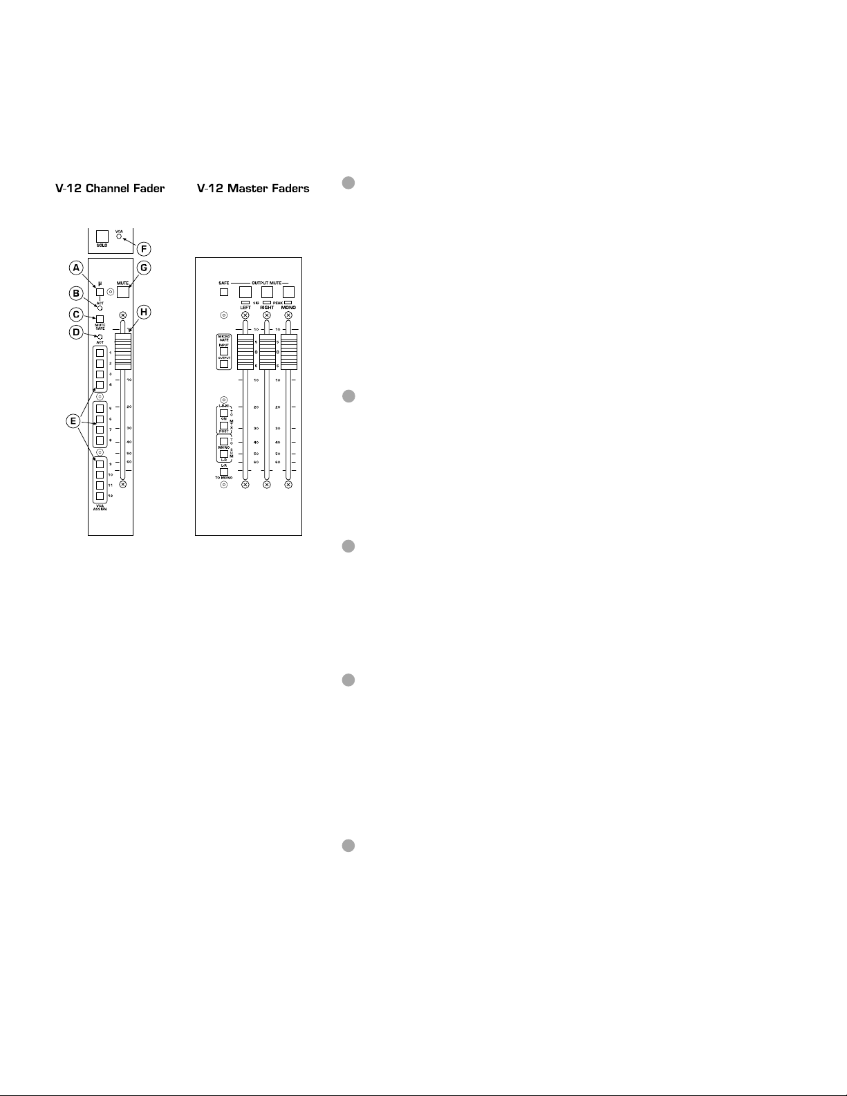
p. 52
0
5
5
micro mute system
channel fader features
µ-button
This momentary switch is used to program the channel mutes when the Micro
is in EDIT Mode. Pressing this switch will assign/un-assign it to a mute scene
(either Sequenced or Manual), the internal yellow LED will blink to show an
assignment.The operator uses these blinking LEDs to review the mute pattern
being edited. These buttons are also used to send MIDI mute info when the
Micro is in normal operation mode and MIDI Mutes is ON (see Utility).
Pressing this switch sends a Note On/Off command that can be recor ded on
an external MIDI sequencer. If a corresponding Note On/Off command is
received,the yellow LED lites up steady,and a mute command is issued to the
channel.
act LED (µ-mute)
This red LED lites whenever a Mute command is issued from the Micro. This
can be from any of the Sequenced or Manual Mute Scenes or fr om a r eceiv ed
MIDI Note command. Whether or not the channel responds to that mute
command is determined by the status of two SAFE switches:the global Input
Micro Safe switch (near master faders),or the channel Mute Safe switch.
mute safe
This switch "safes" the channel from external mute commands (micr o, VCA,
SIP).By default,the VCA and Solo-In-Place (SIP) mute commands are safed,but
there are two jumpers located on each fader circuit board to exclude each of
them.The micro mute commands (Man Mute, Seq Scene or MIDI mutes) are
always affected by the safe.
act LED (VCA)
This red LED lights whenever a m ute command is coming from an assigned
VCA. Each VC A Master has an associated Mute switch.When depressed,any
channels assigned to that VCA Master will go to a fader full-down condition
(max attenuation),and the channel mute will be activated.A jumper in the VCA
Master fader block can defeat the mute function;in that case,the channels still
go to fader full-down,but the channel mute is not activated.
VCA assign
These 12 lit switches are used to assign a channel to any of the 12 VCA
Masters. The channel gain is controlled by the sum of the voltages of the
local fader and any of the assigned VCA Masters.The VCA control circuitry is
designed so that even if a channel is assigned to all 12 masters,and those masters are all at +10dB boost (total of +120dB theoretical gain!),the local fader
(or any Master fader) ,when pulled down,has enough electrical over-travel to
fully attenuate the channel.Furthermore,the control voltage is electrically limited to a maximum of +20dB gain to prev ent excessive channel boost.
A
B
C
D
E
Page 53

p. 53
micro mute system
0
5
5
channel fader features
VCA LED (on module)
This LED glows green to indicate the amount of control voltage applied to
the channel VCA; the greater the control voltage, the brighter the LED.
Often, a channel may be assigned to more than one VCA master, and it is
easy to overlook an assignment and wonder wh y a channel isn’ t on.This LED
gives the operator a quick refer ence to the state of the channel VCA;if there
is no LED indication,there is no VCA control voltage.The LED will turn from
green to red when the contr ol voltage limit of +20dB is reached as detailed
above.This alerts the operator to unusual or incorrect gain settings and prevents any additional fader boost from being applied.
mute button
This latching switch is the local mute switch for the channel.If this switch is
depressed,the channel will mute regardless of anything else.The internal red
LED is the mute indicator for the channel.This will light when the channel is
muted from any source (manual,micro,VCA, SIP).
channel fader
This hi-quality, 100mm fader generates the local control voltage for the
channel.Its voltage is summed with any of the assigned VCA Master voltages
to control the audio level of the VCA in the channel.
F
G
H
Page 54

p. 54
micro mute system
micro operation
normal operation mode
These switches are normally lit and available for use.
GO Switch
BANK SELECT
Scroll UP
Scroll DOWN
1 of 3 from Next Scene:Mute(default), Pgm, Chan
Upper Display shows Next Scene and Lower display shows Active Scene.
Both displays show data in the following format :mmm ppp cc
mmm= Scene # [001 to 128]
ppp= MIDI Pgm # [(OFF), 001 to 128] or [(OFF), 000 to 127]
(Set by Utility Function- MIDI BASE)
cc= MIDI Chan # [01 to 16]
mute scene operation
The Console has the ability to mute its channels and outputs by the use
of Mute Scenes. There are 13 possible Mute Scene sources: 12 Manual
Mutes (1-12), and the Sequenced Scene. There are 3 possible states the
console can operate in as detailed below.Normally the console is set so
that all 13 of the possible Mute sources can be used at the same time.This
state is set by the Utility Function –SCENE OPER.
cummulative
(default)
13 of 13 Scenes possible:Any of 12 Manual Mutes and Seq Scene
single all
Only 1 of 13 Scenes possible:1 of 12 Man Mutes or Seq Scene
single man
2 of 13 Scenes possible:1 of 12 Manual Mutes and Seq Scene
edit mode
This mode allows the operator to set-up,preview or edit an y of the Micro
Mute Scenes.There are (14) possible edit sources:(1)Next Scene [including Rapid Recalls],(12)Man Mutes 1-12 [x12 Banks] and (1)Active Scene.
The µ-Mute switches on each channel and each output are used to
assign/un-assign a mute from the Scene being edited.A momentary press
on the
µ-Mute switch will start/stop it from blinking yellow; the blinking
indicates that a mute is assigned to that Scene.Any or all channels and outputs can be assigned to any Mute Scene. While in Edit Mode , the current
mute state of the console is maintained,the edits made will not necessarily affect the current mutes unless the Scene you are editing was active
when you entered Edit Mode.The following steps describe how to use the
Edit Mode.
1
2
3
Page 55

micro mute system
Select Scene to edit
Press EDIT/PREV ke y- It starts blinking indicating Edit Mode.
Next Scene is the default Edit selection:
MUTE (Next Scene) begins blinking.
Any Chan or Outputs assigned to that Next Scene Mute- their µ-Mutes
begin blinking.
Any one of the 14 above listed sources can be selected for editing.Next
Scene (Mute) is the default,but,also within Next Scene,the MIDI Pgm or
Channel can also be edited.Press PGM or CHAN- it blinks when selected.Use the Scroll Up/Dwn keys to change its value to the new setting.An
* will show up in the display between the Pgm and Chan numbers, indicating a change is pending and the ST ORE sw lites up .If STORE is pr essed,
the change is written into memory and the * goes away.
performing clear/edit/store
While in Edit Mode, select the source to edit.Next Scene (Mute) is the
default selection, press any of the Manual Mutes (1-12) if desired,or Seq
Scene if you want to edit the Active Scene.
The selected source begins blinking,and any m-Mutes associated with that
scene also blink.(The mute data has been loaded into an edit buffer at this
time).
When any µ-Mute sw is toggled (Scene changed from original),the ST ORE
switch lites up indicating that a change to the original Scene has occurredThe change is temporary so far- only the Edit buffer has been affected.If
editing Next Scene or Active Scene,an * shows up to the right of the scene
number in the display showing that something has changed.
If user re-presses the selected (blinking) Scene,the STORE turns off (Edit
buffer reloaded with original scene) and the * after the Mute # in the display is removed
If CLEAR pressed,the Edit Buffer is cleared & CLEAR turns off and ST ORE
lites up.Again,the change is temporary so far- only the Edit buffer has been
affected.
If user re-presses selected (blinking) Mute, STORE turns off (Edit buffer
reloaded with original scene).The CLEAR lite comes back on
If ST ORE pressed:
Current edited or cleared Edit buffer is written back to selected scene-
STORE turns off,and the * in the display is removed.Any edited changes
have no w written over the original Scene memory.
performing copy-and-paste
The Copy and Paste buttons are used within Edit Mode to allo w the operator to copy mute patterns between different scenes and also set the
Rapid Recall keys to new values.(The default values for the Rapid Recall
keys ar e RR#1=10,RR#2=20 … RR#10=100.This allows the operator to
quickly get to any place within the 128 scenes).
The Copy/Paste operation is modeled after the typical operation you
would perform on your computer.A copy of the current desired pattern
is created by using the Cop y key- (the edit/cop y buffer is used for this storage). The user then selects the desired destination scene and pastes the
data into it, this replaces the previous data with the data from the copy
buffer.The micro then returns back to the original edit scene for further
operations. The Copy/Paste operation is only good for one destination.If
Page 56

p. 56
micro mute system
addition destinations are desired for the same copy data, additional
copy/paste cycles are required.
To copy a mute pattern,press the lit COPY key.
CLEAR turns off ,the PASTE s w comes on,the selected edit Mute lite goes
from Blink to steady on.
The User must now either select a paste destination or cancel the copy
operation.
Paste:
User can select any Manual Mute or Next Scene-Mute as paste destina-
tion. The Active Scene is not allowed as a destination.Select the destination source by pressing one of the Manual Mute buttons or the Next
Scene-Mute button.If a copy/paste is being performed within the 128 Seq
Scenes, press the now steady MUTE sw to select it as the source. It will
now start blinking,use the scroll keys to step to the desired destination.
The selected destination Mute blinks and PASTE changes to blink and
CLEAR comes on.
Pressing PASTE writes the Copy data into the destination.
After Paste performed, the system returns back to beginning of the Edit
cycle with original selected scene.
Some limits exist because of the different source and destination data
types:
Only mute data is transferred between Manual Mutes and Sequenced
Scenes.
Cancel:
To cancel a Copy operation,the User can press PASTE before selecting a
destination or can press the original source mute again or can press
CLEAR.Any of these will r esult in the copy operation being cancelled and
the system returning to the edit mode.
edit/previe w rapid recall
Edit/View:
Rapid Recall can be edited or viewed when Next Scene is selected for edit.
With Next Scene(Mute) selected and flashing,pressing any of the 10 RR
buttons transfers the info to the Next Scene display. Since these are just
pointers to the 128 Mute Scenes,this is no different than scrolling up or
down to the scene. Once there,normal editing can take place.The user
can use the RR as jumps to the different scenes instead of ha ving to scroll.
Changing RR:
The value of the 10 RR locations can be changed by using the copy/paste
buttons.
NO TE: The default settings are RR#1=10,RR#2=20,…RR#10=100
When in Edit Mode, scroll the Next Scene display to the desired Mute
Scene.
Press COPY;PASTE lites up- waiting for a destination.(Normally,a desti-
nation Mute would be pressed and it would blink with PASTE). For RR
change,press the desired RR # 1-10.P ASTE goes out,and the Next Display
shows " RR STORED". The paste light goes off and Edit Mode returns to
its previous state.
Page 57

micro mute system
Exiting Edit Mode
The normal way to exit fr om Edit Mode is to Pr ess the blinking EDIT k e y.
The Console returns to Normal Operation Mode:
Other ways to exit Edit Mode:
If editing Next Scene(Mute/Pgm/Chan):Pressing GO puts the edited scene
into Active Scene and then does a normal exit from Edit Mode into
Operation Mode.Any * in the Next Scene displa y ar e maintained and also
transferred to the Active Scene. This exit actually doesn’t change the data
in the Next Scene memory (if STORE wasn’ t pr essed first),the edit buffer
is transferred into the Active Scene,the original Next Scene data remains
intact.This is useful for making a temporary change to a mute scene without affecting the stored info.
Recall Last:
The RECALL LAST key is used to bring back the previous Active Scene.
This is useful when the operator jumps a cue and needs to get back to
where he was before pr essing that GO button.There is a "last buffer" data
storage area that receives the contents of the pr evious Active Scene when
GO is pressed.This buffer is over-written each time GO is used; it is only
good for one recall at a time.The RECALL LAST sw will only be lit if there
is data available to use.If it is lit and then pressed,it will perform its function and then turn off until the buffer is again valid (next time GO is
pressed).
Pressing RECALL LAST does the following:
1
.The current Active Scene is transferred into the Next Scene Display.
2. The previous Active Scene is recalled from last buffer and put into Active
Scene.
3. Any edits that were performed on the pre vious Activ e Scene(if edited when
it was active) or on the current Active Scene are kept during this transfer(i.e.
Asterisks are kept as flags for changes).
4. MIDI info is sent if present.
This is the sequence of events that happens when the GO button or the
RECALL LAST key is used:
Press GO:
Current Active Scene (with edits & flags) is placed into Last Buffer storage
Next Scene Buffer is placed into Active Scene
Next Scene increments up,RECALL LAST sw comes on
MIDI data of new Active Scene is omitted
Press RECALL LAST (if lit):
Current Active Scene(with edits & flags) is placed into Next Scene buffer
Last Buffer is placed into Active Scene
LAST lite goes off (Next Scene # is previous Active Scene #).
RECALL LAST sw now disabled.
MIDI data of new Active Scene is xmitted
4
p. 57
Page 58

p. 58
micro mute system
If an Active Scene had been edited and then RECALL LAST is pressed,the
edited Active Scene is transferred up to the Next Scene display.The only
thing that could have been edited on the Active Scene was the mute pattern. The Mute Scene number would have remained the same. The
restored Next Scene now is showing an * to the right of the Mute #.If the
user presses EDIT to enter Edit Mode,the STORE lite will come on indicating that this data is changed from what is stored in that Mute Scene.
Pressing ST ORE will write the edited data into the scene and the * will g o
away and the STORE lite will go out.
Utility Mode
A number of Utility Functions are pro vided for the user.
A more detailed list follows the set-up description.
From Operation Mode: Press UTILITY key- it starts blinking, indicating
Utility Mode.
Lower displa y shows Utility Function (MIDI Chan,Base #,Mute Mode,etc)
Upper Display shows value/setting (0-16,0-1,CUMULATIVE,etc).
Scroll Up/Dwn steps through the functions in the lower display,
upper display shows it’s current value.
To change a value/setting:
Press EDIT button- it lites up and now Up/Dwn scrolls through possible
settings in upper display.
If applicable to the setting,the CLEAR or STORE sw lites up.
Once scrolled away from the current setting,the STORE button lites up.
User must press ST ORE to set new value,or press EDIT (lite goes off) and
use the Up/Dwn to select another function in lower display.
Once ST ORE is pressed,the new value is set and EDIT goes off as above.
Up/Dwn now select next function.
To Exit- user presses UTILITY.It stops blinking and the Console returns
to Operation Mode.
Utilities:
Function Name Value (default is listed in first column)
(In Lower Display) (In Upper Display)
MIDI Utilities
MIDI_CHAN 1 1-16
MIDI_BASE BASE 1 BASE 0
MIDI_PCHNG SEND RECEIVEBOTH OFF
MIDI_MUTES ON OFF
MIDI_LOAD DISABLED ENABLED
MIDI_DUMP PRESS_ST OR
5
Page 59

micro mute system
Clear Utilities
CLR_SEQ_MT PRESS_CLR
CLR_SEQ_PC PRESS_CLR
CLR_MM_BNK PRESS_CLR
CLR_MM_ALL PRESS_CLR
Show Control
SHOW_CTRL OFF ON
General Controls
BRIGHTNESS BRIGHT_=_5 1-7
REV_LEVEL REV_0.94
Micro Utilities
MAIN_MICRO ON OFF
MAN_MUTES ON OFF
SEQ_SCENES ON OFF
SCENE_OPER CUMULATIVE SINGLE_ALL
SINGLE_MAN
RPD_RECALL TO_NEXT TO_ACTIVE
TO_ACT+NEXT
PASSWORD SET_PSWORD CLR_PSWORD
UTILITY DETAILS
MIDI Utilities
MIDI CHAN Sets Default MIDI Channel –Used for MIDI Mutes, PgmChng
and Dump.Chan for Next Scene defaults to this;user can change Chan per
Scene.
MIDI BASE Pgm Change Range 1-128 or 0-127
MIDI PCHNG Sets mode of MIDI Pgm Change.Pgm Change received only if
on correct MIDI channel (set above)
SEND PgmChng sent (if present in Scene)
when loading Active Scene (GO,RR or LAST)
RECEIVE Incoming PgmChng command on correct MIDI chan
sets Active Scene.
Display shows XXX RCVD (XXX=Pgm # in selected MIDI base)
BOTH Send and Receive both active
OFFNo Pgm Chng sent or received (Overrides individual Scene settings)
MIDI MUTES Sets mode of individual MIDI Mutes (Note On/Note Off).
Note: MIDI Mutes not active while in Edit Mode.
ON MIDI Note info sent when a µ-Mute is pressed.
p. 59
Page 60
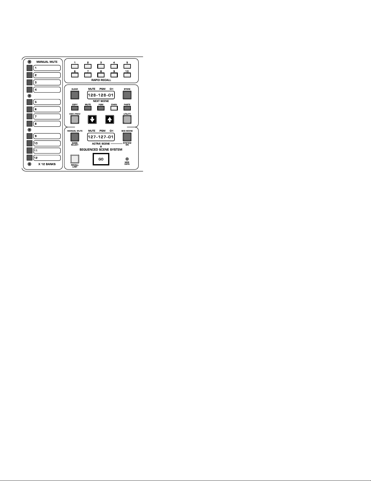
p. 60
micro mute system
MIDI Note info received on corr ect MIDI chan controls Chan m utes(for pla yback from MIDI sequencer)
OFF No Note info sent or received
MIDI LOAD Reloads Mute Scenes & Manual Mutes.
Uses Sysex command for dump and load.
MIDI DUMP Dumps all 128 Mute Scenes and all banks of Manual Mutes.
Clear Utilities
CLR SEQ MTClears all mutes in the 128 Seq Scene memories
CLR SEQ PC Clears (sets to off) all MIDI Pgm Chngs in the 128 Scenes- MIDI
channel set back to default
CLR MM BNK Clears all Manual Mutes in curr ent Bank
CLR MM ALL Clears all Manual Mutes in all Banks
Show Control
SHOW CTRL NOTE: If Show Control is ON,the V-12 Micro is put into
Show Control Mode. The GO button no longer controls Next Scene to
Active Scene transfer. The Manual Mutes will still function, but the
Sequenced Scene system is disabled (no GO command) along with the
Edit Mode.
Currently,this is the list of MSC data that the V-12 supports (V-12 soft
ware Rev 0.94)
The V-12 only sends MSC data (Note:MSC = MIDI Show Control)
OFF Normal Console Operation
ON Lower Displa y reads "SHOW CTRL "
Upper Display reads "STOP RSM"
Pressing GO sends MIDI Show Ctrl "GO" command
Pressing MUTE sends MSC "STOP" Command
Pressing CHAN sends MSC "RESUME" command
Pressing UP ARROW sends MSC "Standby +"" command
Pressing DOWN ARROW sends MSC "Standby -" command
Pressing RECALL LAST sends MSC "LAST" command
General Controls
BRIGHTNESS
Sets brightness of both Next and Active displays.
REV LEVEL Show current Software Revision level: (This info correct for
REV 0.94)
MUTE MODE Sets how many of the possible 13 Mute Scenes can be active
at the same time:
12 Man Mutes,1 Seq Mute
CUMULATIVE13 of 13 Scenes possible:Any Manual Mutes and Seq Scene
SINGLE_ALL Only 1 of 13 Scenes possible: 1 of 12 Man Mutes or Seq
Scene
Page 61
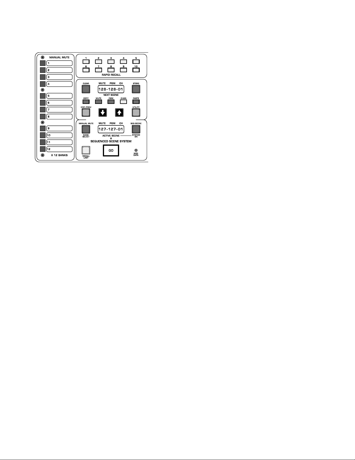
micro mute system
SINGLE_MAN 2 of 13 Scenes possible: 1 of 12 Manual Mutes and Seq
Scene
Micro Utilities
MAIN MICRO If set to OFF,completely disables Micro section.Both displays and all buttons are turned off.
Note: If this setting is selected, upon exiting Util Mode, the micro will
appear to be non-functioning.No lites or displays will be on.The only button
that will do anything is the UTILITY key.Press this ke y to get back into UTILITY Mode. If Password is set along with Main Micro Off, the only way for
someone to restore any micro function is to enter the correct passw or d and
change the Micro setting.
MAN MUTES If set to OFF,disables the Man Mutes from being accessed or
edited.Man Mute & Bank Sel Switches all off.
SEQ SCENES If set to OFF, disables the Seq Mutes from being accessed or
edited.Next Scene and Active Scene Displays off, NEXT, LAST,SEQ SCENE
all off.
RPD RECALL
Determines what happens when a Rapid Recall (RR) button is
pressed in Operating Mode.
T O NEXT
RR Scene# is placed into Next Scene Display ,Active Scene unaf-
fected
T O ACTIVE
RR Scene # is sent directly to Active Scene.Next Scene is unaf-
fected.
TO ACT+NXT
RR Scene # is sent directly to Active Scene.Next Scene is set
to value of RR Scene# +1.
P ASSW ORDSET_PSWORD
Allows the user to set a password to control access to the Utility functions.Password comes up as last option in Utility
menu by default.If no password is currently set,SET_PSWORD shows in the
upper display and the STORE key is lit.Pressing STORE changes upper display
to ENTR_PSWRD and the lower display to PSWRD=????. RR keys 1-10 are
used to enter the password,4 digits only .Each press of a RR ke y changes a "?"
to an "*".When initially setting a password,the user is prompted to enter it
twice to insure that it is correct. Once a password has been successfully
entered,the system exits Utility mode.
PSWRD=???? Once a password has been set, the user is asked to enter a
password whenev er the Utility Mode is selected.ENTR_PSWRD shows in the
upper display, and PSWRD=???? is on the lower display. Further access to
Utilities is locked out unless the correct password is entered.Each press of a
RR key changes a "?" to an "*"
Once 4 digits are entered:
If incorrect- Display shows:"TRY _AGAIN".There is no limit to the
amount of entry attempts.
If correct- User is allowed access to Utilities- first function in Utility
list is then displayed.
Note:The password remains active until it is cleared (with the
CLR_PSWORD function).
CLR_PSWORD
Once a correct password has been entered,the user has
the option of clearing the password (returns password to default OFF state)
Page 62

p. 62
micro mute system
when he scrolls to PASSWORD again before leaving the Utility Mode.Press
CLEAR to clear the password to Off.
RESETTING THE MICRO:
The V-12 micro is designed for reliable,trouble-free operation ,but it
is,after all,a computer .There ma y be situations wher e it misbeha v es.If this
occurs,a reset is probably the best course of action.There are two types
of reset: a normal, maintained reset; and a second, more encompassing
reset- the Initialization Reset:
The first type occurs every time the V-12 powers up.The micro does
some housekeeping,counts the number of channels present,and restores
the Console’s mutes to their state prior to the last power-down. It does
this in less than a second.All mute and scene information is retained along
with any utility settings.
The second type of reset completely clears out the micro .In addition
to clearing out all micro scratch memory,all utility functions are reset to
their starting values and all mute and scene memories are cleared. This
takes about a second,and you will be left with a console with no preset
mutes and all settings at their factory defaults.
There are two methods to initiate a maintained reset:
The first is by powering the console down,waiting a second or so,and
then back up.This method will, of course , cause audio discontinuities.The
V-12 has power -up/down,anti-pop circuitry on all main balanced outs,but
there will be a delay while the power supply comes up to spec and the
main outs are muted.
The second method is to use the reset hole located below the Active
Scene display.A straightened paper clip or push-pin can be used to trip the
recessed reset switch.This will cause the micro to go through its normal
power-up sequence- it will be ready to go in a flash (you may not e ven see
the displays blink).The pow er supply is not involv ed,so normal audio operation is maintained.
To perform a Initialization Reset,two buttons are held down on the keypad while the micro is going thru a normal reset.You can do this when the
console is powering up or you can start it by pressing the reset switch.
Hold down the CLEAR and EDIT keys while a r eset is performed.The displays will clear out, and MEM INIT will appear in the upper display.
Continue to hold the keys down until the normal Next/Active Scene displays show up .The V-12 is set to this state when it leaves the factory .There
is no danger (other than data loss with the Init Reset) in doing either of
these resets,the only warning involves audio that may become un-muted
as a result.Please use caution if you are working on a live system.
Page 63

p. 63
Page 64
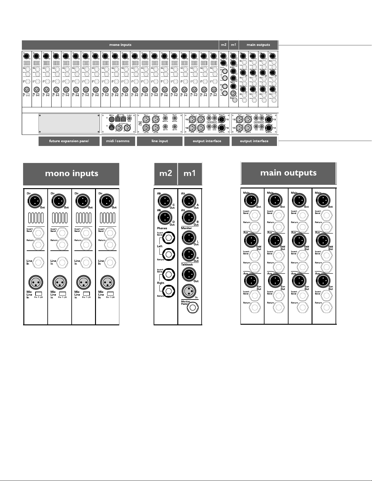
V12 rear views
Page 65

Page 66

V12 rear views
Page 67
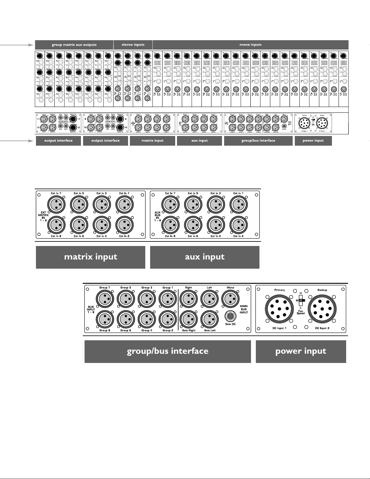
 Loading...