

Page 1
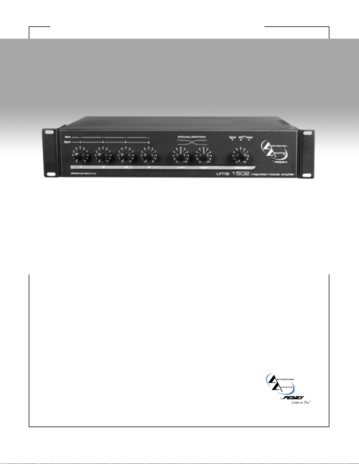
UMA™1502 MIXER/AMPLIFIERSpecifications
SSppeecciiffiiccaattiioonnss
RRaatteedd oouuttppuutt ppoowweerr::
150 Watts
OOuuttppuutt rreegguullaattiioonn::
Direct out: <0.5 dB
Transformer out: <1.0 dB
FFrreeqquueennccyy rreessppoonnssee::
Power Amplifier: ±0.5 dB, 20 Hz to 20 kHz,
direct out
±1.0 dB, 50 Hz to 20 kHz,
transformer out
Preamplifier: ±1.0 dB, 20 Hz to 20 kHz
TTHHDD::
Power Amplifier: 0.05% (1 kHz)
Preamplifier: 0.10% with nominal gain
settings
PPoowweerr bbaannddwwiiddtthh::
Direct out: <10 Hz to 70 kHz
Transformer out: 30 Hz to 40 kHz
SSiiggnnaall//nnooiissee::
(22 Hz — 22 kHz) typical
All controls CCW: -100 dB
All controls nominal (5): -90 dB
Level controls CCW and master level CW:
-80 dB
OOuuttppuuttss::
Direct out: 4 Ohms (25 V)
XFMR: Balanced 8 Ohms,
70 V, 100 V
Ch. 4 out: 1 V nom., +21 dBu max.
at 100 Ohms
Pre out: 1 V nom.; +21 dBu max.,
at 100 Ohms
IInnppuuttss::
Channel 1: Mic 1 mV at 1.8 k Ohms
(XLR or screw terminals)
Tel 100 mV at 20 k Ohms
(Screw terminals)
Channel 2: Mic 1 mV at 1.8 k Ohms
(Screw terminals)
Line 100 mV
at 20 k Ohms
(Screw terminals)
Channel 3: Line 100 mV
at 20 k Ohms
(Screw terminals)
Channel 4: Line 100 mV
at 20 k Ohms
(Screw terminals)
Stereo 316 mV
(-10 dBV) at
4.0 k Ohms
(RCA jacks)
Power in: 1 Volt at 20 k Ohms
TToonnee ccoonnttrroollss::
Bass: ±10 dB at 100 Hz
Treble: ±10 dB at 10 kHz
FFrroonntt ppaanneell ccoonnttrroollss aanndd iinnddiiccaattoorrss::
Channel 1 level control
Channel 2 level control
Channel 3 level control
Channel 4 level control
Bass control
Treble control
Page 2

UMA™1502 MIXER/AMPLIFIERSpecifications
Master level control
Input channel signal level indicators:
(signal presence = green; signal peak
= red)
Input channel mute status
Power amplifier signal presence
indicator
SPS
™
indicator
Power on indicator
RReeaarr ppaanneell ccoonnttrroollss::
Module input level control use with
MMA input modules only
Channel 1 sensitivity switch
Channel 1 mute bus assign switch
Mute 2 threshold control
Channel 2 sensitivity switch
Channel 2 mute bus assign switch
Channel 4 output level control
Loop switch
Power switch
MMuuttiinngg::
Mute 1: MMA input module overrides
Ch 1 through 4
Mute 2: Ch 1 overrides Ch 2 through 4
with adjustable threshold control range
from OFF to 100 mV (TEL) or 1 mV (MIC)
OOtthheerr ffeeaattuurreess::
Remote volume control (RVC) via screw
terminals
• 10 k Ohms approximately 30 dB
attenuation
• 100 k Ohms approximately 60 dB
attenuation
Mute 1 and mute 2 bus activation with
switch contact closure via screw
terminals
24 V DC phantom power on MIC inputs
PPoowweerr rreeqquuiirreemmeennttss::
300 Watts, 120 V AC, 60 Hz
DDiimmeennssiioonnss ((aallll mmooddeellss))::
19" x 13.25" x 3.45" with rack ears
(483 mm x 337 mm x 88 mm)
17" x 13.25" x 3.45" without rack ears
(432 mm x 337 mm x 88 mm)
WWeeiigghhtt::
27.1 lbs. (12 kg)
CCoolloorr::
Black
FFeeaattuurreess
• Up to five input channels
• One electronically balanced Mic/Tel
input – telephone input with 600 Ohm
transformer balanced for paging
• One electronically balanced Mic/Line
input
• Two electronically balanced Line inputs
• One plug-in module port allows for any
single-space MMA
™
module
• Rear-panel input level control for
optional MMA input module
• Priority/Muting system with internal
signal override, external switch closure
capability, threshold control, and front
panel indicators
• Mute Bus Active/Defeat switches on
two channels
• Remote volume control capability
• Bass and treble equalization controls
• Preamp output and power amp input
loop for external processing equipment or
auxiliary output
• Channel 4 electronically balanced
output provides non-mutable output for
MOH
• Front panel channel input signal level
indicators
• Amplifier signal indicator
• SPS
™
(Speaker Protection System)
circuitry with indicator
• Power indicator
• 4 Ohm direct output
• 8 Ohm, 70 Volt, and 100 Volt
transformer-balanced power outputs
• AC convenience outlet (120 V units
only)
• Optional rack mounting with included
rack ears
AApppplliiccaattiioonnss
• Presentation rooms
• Board rooms
• Courtrooms
• Auditoriums
• Lecture halls
• Meeting rooms
• Convention centers
• Paging systems
• Background music
• Retail spaces
• Restaurants
DDeessccrriippttiioonn
The UMA 1502 are high quality,
commercial grade analog audio
mixer/amplifiers. Designed for flexibility
in application, these mixer/amps
represent the latest, state-of-the-art
technology in analog circuit design.
Powerful, yet easy to use, the new UMA
1502 delivers amazing sonic performance.
Low-noise design and features applicable
to “real-world” situations makes this unit
ideal for audio applications where a
compact, powered mixer with multiple
input and output capabilities are
required.
AArrcchhiitteeccttuurraall aanndd EEnnggiinneeeerriinngg
SSppeecciiffiiccaattiioonnss
The mixer/amplifier shall have 4-inputs and
an accessory module port for use with
present and future Peavey MMA modules.
The front panel shall include four input
level controls, bass and treble controls, and
a master output control. Front panel
indicators shall include power, signal
presence at the amplifier, channel signal
and mute condition, and SPS
™
. The mixer
amplifier shall have a hierarchical muting
function where the input module has the
highest priority followed by Channel 1.
Outputs shall include one direct and three
transformer-balanced. The power switch
shall be on the rear panel along with the
detachable IEC cord, fuse holder, and
accessory power outlet (120 V only).
There shall be four inputs with Euro-type
connectors on the rear panel and level
controls on the front panel. Channel 1 shall
also include an XLR connector and have a
bridging transformer input with switchable
input sensitivity between telephone paging
and microphone. When in the microphone
mode, 24 Volt phantom power shall be
applied to the Input 1. Channel 2 shall be
electronically balanced with a switchable
input sensitivity between mic and line
levels. When in the microphone mode, 24
Volt phantom power shall be applied to the
Input 2. Channels 3 and 4 shall be
electronically balanced line-level inputs
with Channel 4 including stereo RCA jacks.
Additionally, the output from Channel 4
input shall be made available via an
electronically balanced output with a Eurotype connector and a separate level
control. The module port shall be capable
of controlling both mute buses. Depending
upon the module chosen, it can be set up
for master configuration. When the input
signal to an input module commands a
mute function, Channels 1-4 shall be
muted.
Only Channel 1 shall have a continuously
variable mute threshold control on the rear
panel. Setting this control fully clockwise
shall defeat the Channel 1 mute function.
The mute level threshold for Channel 1
shall be increased as the control is turned
clockwise. When the signal level in Channel
1 exceeds the mute threshold, Channels 2-4
shall be muted. Channels 1 and 2 shall
include a switch to defeat its muting
function. When the switch is out, the
channel shall be muted. When the switch is
in, the channel cannot be muted.
Page 3

UMA™1502 MIXER/AMPLIFIERSpecifications
The master section shall include front panel
bass and treble EQ controls, each with a
±10 dB range of operation. A front panel
master level control shall control the output
signal level of the preamp/mixer. The
capability to insert an external device shall
be included via two RCA jacks. A loop
switch shall bypass the loop point. Remote
master level control capability shall be
included along with remote control for each
mute bus.
The mixer amplifier shall have a direct 4
Ohm output, and 3 transformer-balanced
outputs – 100 Volt, 70 Volt, and 8 Ohm. The
amplifier shall include clipping protection
via SPS™. The unit shall be called the
Peavey Architectural Acoustics Division
model UMA 1502.
WWaarrrraannttyy
Three + two limited warranty
Note: For details, refer to the warranty
statement. Copies of this statement may be
obtained by contacting Peavey Electronics
Corporation, P.O. Box 2898, Meridian,
Mississippi 39302-2898.
CH 1
LEVEL
CH 2 IN
MASTER
LEVEL
SPS
MU TE2
THRESH
-
PA
CH 2
LEVEL
+
-
MASTER
LEVEL
CONTROL
MOD ULE
PO RT
+
PREAMP
MIC
HIGH
LINE
+24V
PWR
IN
LOW
PRE
OUT
LOOP
PREAMP
SIGNAL
MU TE2
SENS
MU TE1
CH 1 IN
INPUT
LEVEL
MU TE1
-
+
MIC
TEL
TELMIC
MIC
SENS
GNDINOUT
24V
MUTE 2
MUTE 1
ACTIVE
DEFEA T
SIGNAL MUTE
MU TE2
DEFEA T
ACTIVE
CH 1
STEREO IN
CH 4 OUT
LEVEL
R
CH 4
LEVEL
PREAMP
CH 3
LEVEL
L
PREAMP
CH 3 IN
+
-
-
+
CH 4 IN
BYPASS
ENAB LE
EXT
1
RVC
2CV
MUTE
SHD
CH 4 OUT
+
-
8 4 GNDXFMRCOM70V100V
OUTP UTS
AC RECEPTACLE
(120V UNIT ONLY)
POWER SUPPLY
AC Input
Fuse
Power
Switch
POWER
SIGNAL MUTE
MUTESIGNAL
MUTESIGNAL
+Vhi
-Vhi
+Vlo
-Vlo
+Vmod
+Vfan
24V
+V
HILO
L
N
G
Page 4

Peavey Electronics Corporation • 711 A Street • Meridian, MS 39301
601-483-5376 • Fax 601-486-1678 • http://aa.peavey.com
©2002 Printed in the U.S.A.
UMA™1502 MIXER/AMPLIFIERSpecifications
UMA™1502 MIXER/AMPLIFIER FRONT
UMA™1502 MIXER/AMPLIFIER BACK
FUSE
 Loading...