

Page 1

Cover for T-MAX™
1
Page 2

Intended to alert the user to the presence of uninsulated "dangerous voltage" within the product's enclosure
that may be of sufficient magnitude to constitute a risk of electric shock to persons.
Intended to alert the user of the presence of important operating and maintenance (servicing) instructions in the
literature accompanying the product.
CAUTION: Risk of electrical shock – DO NOT OPEN!
CAUTION: To reduce the risk of electric shock, do not remove cover. No user serviceable parts inside. Refer servicing to
qualified service personnel.
WARNING: To prevent electrical shock or fire hazard, do not expose this appliance to rain or moisture. Before using this
appliance, read the operating guide for further warnings.
Este símbolo tiene el propósito de alertar al usuario de la presencia de "(voltaje) peligroso" que no tiene
aislamiento dentro de la caja del producto que puede tener una magnitud suficiente como para constituir riesgo de
corrientazo.
Este símbolo tiene el propósito de alertar al usario de la presencia de instruccones importantes sobre la operación
y mantenimiento en la literatura que viene con el producto.
PRECAUCION: Riesgo de corrientazo – No abra.
PRECAUCION: Para disminuír el riesgo de corrientazo, no abra la cubierta. No hay piezas adentro que el usario pueda
reparar. Deje todo mantenimiento a los técnicos calificados.
ADVERTENCIA: Para evitar corrientazos o peligro de incendio, no deje expuesto a la lluvia o humedad este aparato
Antes de usar este aparato, lea más advertencias en la guía de operación.
Ce symbole est utilisé pur indiquer à l'utilisateur la présence à l'intérieur de ce produit de tension non-isolée
dangereuse pouvant être d'intensité suffisante pour constituer un risque de choc électrique.
Ce symbole est utilisé pour indiquer à l'utilisateur qu'il ou qu'elle trouvera d'importantes instructions sur
l'utilisation et l'entretien (service) de l'appareil dans la littérature accompagnant le produit.
ATTENTION: Risques de choc électrique – NE PAS OUVRIR!
ATTENTION: Afin de réduire le risque de choc électrique, ne pas enlever le couvercle. Il ne se trouve à l'intérieur
aucune pièce pouvant être réparée par l'utilisateur. Confier l'entretien à un personnel qualifié.
AVERTISSEMENT: Afin de prévenir les risques de décharge électrique ou de feu, n'exposez pas cet appareil à la pluie
ou à l'humidité. Avant d'utiliser cet appareil, lisez les avertissements supplémentaires situés dans le guide.
Dieses Symbol soll den Anwender vor unisolierten gefährlichen Spannungen innerhalb des Gehäuses warnen, die
von Ausreichender Stärke sind, um einen elektrischen Schlag verursachen zu können.
Dieses Symbol soll den Benutzer auf wichtige Instruktionen in der Bedienungsanleitung aufmerksam machen, die
Handhabung und Wartung des Produkts betreffen.
VORSICHT: Risiko – Elektrischer Schlag! Nicht öffnen!
VORSICHT: Um das Risiko eines elektrischen Schlages zu vermeiden, nicht die Abdeckung enfernen. Es befinden sich
keine Teile darin, die vom Anwender repariert werden könnten. Reparaturen nur von qualifiziertem Fachpersonal
durchführen lassen.
ACHTUNG: Um einen elektrischen Schlag oder Feuergefahr zu vermeiden, sollte dieses Gerät nicht dem Regen oder
Feuchtigkeit ausgesetzt werden. Vor Inbetriebnahme unbedingt die Bedienungsanleitung lesen.
2
Page 3

Congratulations on the purchase of the Peavey T-MAX® bass amp! The two channel bass system
is unlike any other amp available today. Not only does the T-MAX utilize tube technology for
that smooth tube sound, but the T-MAX also has a completely independent solid-state channel!
Two separate channels that are footswitchable and combinable make for an extremely versatile
piece of gear. Besides the clean contemporary sound, the T-MAX is also capable of producing a
smooth tube-distortion sound that can't be found in any modern solid-state bass rig!
FEATURES:
– 1/4" input with -10 dB pad switch
– Active low- and high-shelving EQ with 7-band graphic EQ
– Front panel channel select and channel combine switches
– Channel active LEDs
– Variable (100 Hz - 1 kHz) third-octave crossover with
frequency and balance controls
– Front panel graphic in/out switch
– Footswitchable: channel select, graphic in/out, and effects loop
– Low Z balanced line out with pre/post EQ switch
– Ground lift switch for line out
– Two paralleled speaker jacks
– Preamp out/power amp in jacks
– Crossover low and high out jacks
– Effects send and return jacks
– Effects high and low level switch
– Two-rack-space package
3
Page 4
E N G L I S H
E N G L I S H
1
2
4
3
5 678
9 111213
10
15 17
14 16 19
18
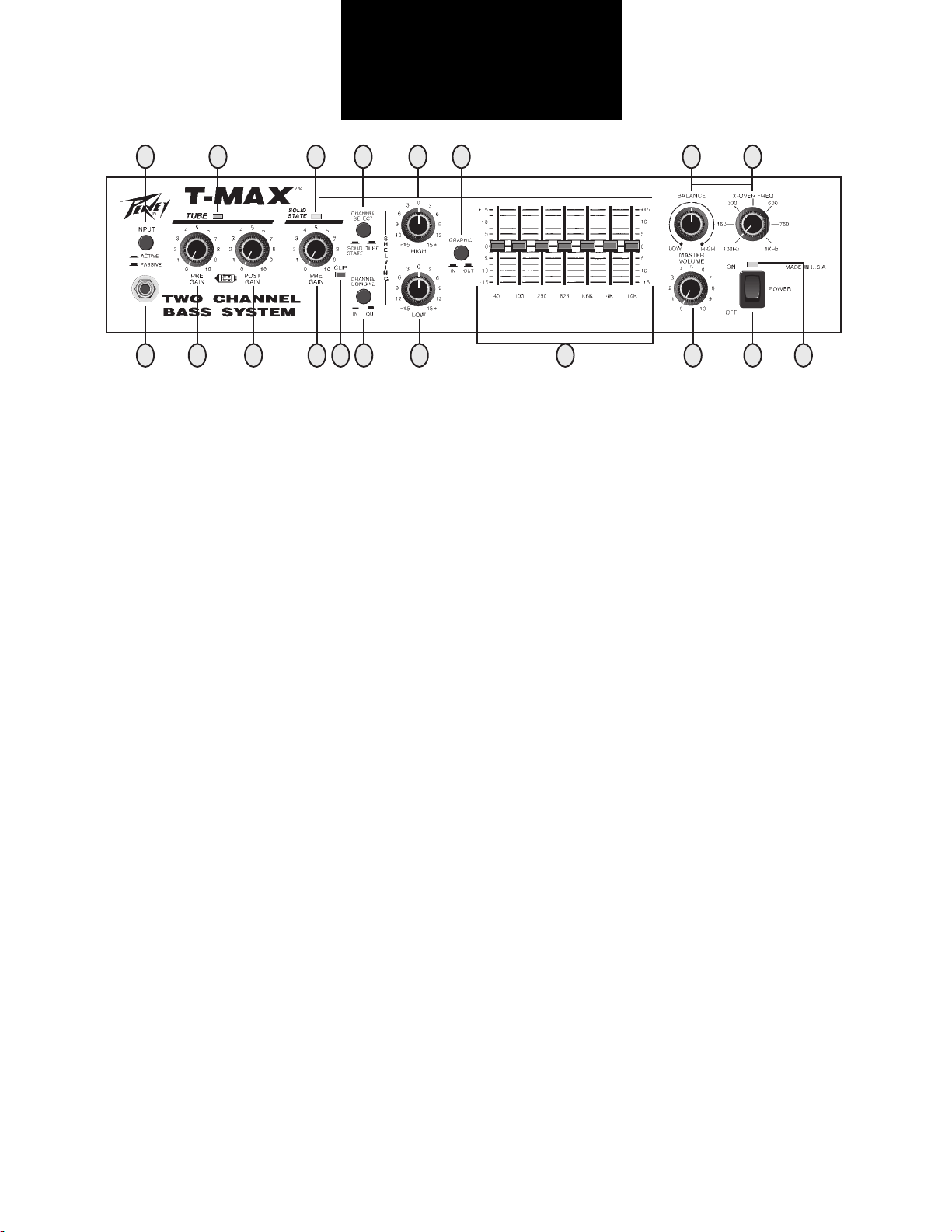
INPUT PAD SWITCH (1)
Provided for instruments that have extremely high output, which can result in overdriving (distorting) the input
gain stage. Depressing the switch to its "in" position reduces the level of the input signal by 10 dB.
INPUT (2)
This input will accept signals from all types of bass pickups.
PRE GAIN (3)
Controls the input gain of the tube channel.
CHANNEL STATUS LED (4)
Illuminates when channel is activated.
POST GAIN (5)
Controls the overall volume level of the channel. The master volume adjustment should be made after the desired
sound has been achieved.
PRE GAIN (6)
Controls the input gain of the solid-state channel.
CHANNEL STATUS LED (7)
Illuminates when channel is activated.
INPUT CLIP INDICATOR (8)
This LED indicates (when lit) that the input gain stage is being overdriven (distorted). Depressing the input pad
switch to its "in" position or reducing the pre gain will alleviate this problem.
CHANNEL SELECT SWITCH (9)
Allows selection of the tube or solid-state channel. The "in" position of the switch selects the solid-state channel,
and the "out" position selects the tube channel.
NOTE: Channel selection may also be accomplished by the remote footswitch. If the remote selection is desired,
the select switch must be in the "out" (tube) position.
CHANNEL COMBINE SWITCH (10)
Allows selection of single channel or combined channel operation. The "in" position of the switch selects combined channel operation where both channels operate simultaneously. The "out" position selects single channel
operation.
HIGH (11)
An active tone control (shelving type, ±15 dB) that varies the high frequency boost or cut.
4
Page 5
LOW (12)
An active tone control (shelving type, ±15 dB) that varies the low frequency boost or cut.
GRAPHIC SELECT (13)
The "in" position of this switch routes the signal through the graphic equalizer. The "out" position removes the
graphic equalizer from the signal path.
7-BAND GRAPHIC EQ (14)
A 7-band, two-and-one-half-octave graphic equalizer that provides 15 dB of boost or cut at each center frequency.
CROSSOVER BALANCE CONTROL (15)
Controls the relative levels of output signals from the crossover. Adjusting this control will only affect signals at
the High Range Output Jack and the Low Range Output Jack on the rear panel. All other output signals are
unaffected by this control.
MASTER VOLUME (16)
Controls the overall volume level of the system.
CROSSOVER FREQUENCY (17)
The frequency control varies the crossover frequency from 100 Hz to 1 kHz.
POWER LED/DDT™ INDICATOR (18)
The LED is green when the power switch is in the "on" position. During normal operation, this LED also acts as a
DDT™ indicator. The LED illuminates "red" when DDT™ power amp compression is taking place.
POWER SWITCH (19)
Used to turn AC mains power on or off.
3332313029282725 2624232220 21
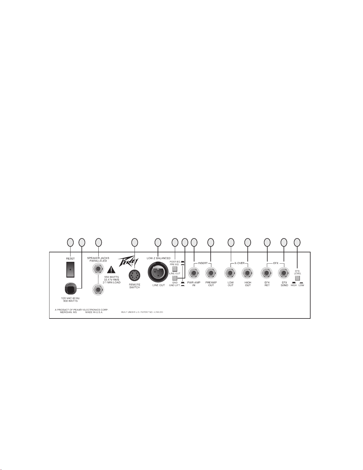
CIRCUIT BREAKER (20)
This breaker is provided to limit the current to the power transformer, and thereby protect it from overheating and
possible destruction due to faulty conditions in the amplifier. The trip current value has been carefully chosen to
allow continuous power output performance, while still providing adequate protection for the power transformer.
Normally this breaker should not trip unless there is a fault in the amplifier circuitry that draws excessive mains
current. However, abnormal conditions, such as a short circuit or continuous operation at overload or clipping,
will cause the breaker to trip. If this occurs, simply reset the breaker and correct the cause of the overload. When
tripped, the button on the breaker will be outward nearly 1/2" and can be reset by pushing inward. A normal reset
button length is about 1/4". If this “thermal” type breaker does trip, then simply pushing the button back in will
reset it after waiting a brief period of time to allow it to cool down. If the breaker trips instantly each time you
attempt to reset it, then the unit should be taken to a qualified service center for repair.
5
Page 6

LINE CORD (120 V PRODUCTS ONLY) (21)
For your safety, we have incorporated a 3-wire line (mains) cable with proper grounding facilities. It is not
advisable to remove the ground pin under any circumstances. If it is necessary to use the equipment without
proper grounding facilities, suitable grounding adaptors should be used. Less noise and greatly reduced shock
hazard exist when the unit is operated with the proper grounded receptacles.
SPEAKER JACKS (22)
Provided for connection of external speakers or speaker enclosure. Minimum total impedance is 2 ohms.
REMOTE SWITCH DIN JACK (23)
Provided for optional footswitch. Allows remote selection of channel select, graphic in/out, and effects loop (post
EQ).
LINE OUT (LOW Z BALANCED) (24)
An XLR jack is provided to route the signal to mixing/recording consoles. This output can be selected pre or post
EQ.
LINE OUT SELECT SWITCH (25)
Allows selection of pre EQ or post EQ to the Low Z balanced line out jack. The “in” position selects pre EQ line
out, and the “out” position selects post EQ line out.
LINE OUT GROUND LIFT SWITCH (26)
Provides ground to be made from the line out jack or lifted to eliminate ground loop from unit and external
source. There may be some situations when audible hum and/or noise will come from the loudspeaker. Select the
ground switch to either the in or out position to minimize the noise.
POWER AMP INPUT (27)
Used to connect line level signal to the power amplifier.
PREAMP OUT (28)
The preamp output can be used to route the amplified signal to a mixing console, tape recorder, etc. Connect the
preamp output using a shielded cable to an input of the tape recorder, mixer, etc. This patch does not affect the
operation of the amplifier.
CROSSOVER (LOW OUT) (29)
Provides a post crossover low-range output signal. Signal level is adjusted by the master volume control and the
crossover balance control.
CROSSOVER (HIGH OUT) (30)
Provides a post crossover high range output signal. Signal level is adjusted by the master volume control and the
crossover balance control.
EFFECTS RETURN (31)
Input for returning signals from external low-level effects or signal processing equipment.
EFFECTS SEND (32)
Output for supplying signals to external low-level effects or signal processing equipment.
EFX LEVEL SWITCH (33)
Selects the effects loop operating level: -10 dBV (3 V RMS) when in low position and 0 dBV (1 V RMS) when in
high position.
6
Page 7

SPECIFICATIONS
POWER AMP SECTION
Power Output with DDT™
Compression Active:
200 W RMS into 8 ohms
350 W RMS into 4 ohms
500 W RMS into 2 ohms
Input Sensitivity:
Input signal necessary for full
output = 1.7 V RMS
DDT™ Dynamic Range:
Greater than 20 dB
DDT™ Maximum THD:
Below 0.6% THD for 6 dB overload
Below 1% THD for 16 dB overload
Hum & Noise:
Greater than 95 dB below rated
power
Power Consumption:
Domestic: 900 watts @ 120 V AC,
60 Hz
Export: 900 watts @ 220-240 V AC,
50/60 Hz
PREAMP SECTION
All measurements are with the following settings except where noted.
Note: Tube channel is designed to
produce distortion when pre
gain control is set greater than
3 (dependent on input signal).
Note: All signals referenced to
1 V RMS = 0 dB.
Solid-State Pre Gain @ 5
Master Volume @ 5
-10 dB Pad Out
All EQ Sliders @ 0 (Centered)
Low and High Shelving @ 0
Input Signal Levels:
Solid-State Channel, -10 dB
Pad Out
Nominal Input: 0.14 V RMS,
-17 dB
Minimum Input: 16 mV RMS,
-36 dB
Maximum Input: 2.0 V RMS,
+6 dB
Solid-State Channel, -10 dB
Pad In
Nominal Input: 0.422 V RMS,
-7.5 dB
Minimum Input: 50 mV RMS,
-26 dB
Maximum Input: 6.0 V RMS,
+15.5 dB
Tube Channel, -10 dB Pad
Out, Post Gain @ 5
Nominal Input: 0.054 V RMS,
-25.3 dB
Minimum Input: 5 mV RMS,
-46 dB (Post Gain @ 10)
Maximum Input: 1.0 V RMS,
+0 dB (For Clean Signal)
Tube Channel, - 10 dB Pad In
Nominal Input: 0.160 V RMS,
-16 dB
Minimum Input: 15 mV RMS,
-36.5 dB (Post Gain @ 10)
Maximum Input: 3 V RMS,
+9.5 dB (For Clean Signal)
Effects Loop (Post EQ):
Send Level (High Setting): -7 dB
Send Level (Low Setting): -15 dB
Return Level (High Setting): -7 dB
Return Level (Low Setting): -15 dB
Crossover:
Low Output Levels:
Nominal: 1.7 V RMS, 4.6 dB
Maximum: 8 V RMS, +18 dB
High Output Levels:
Nominal: 1.7 V RMS, 4.6 dB
Maximum: 8 V RMS, +18 dB
Full Range Output Levels:
Nominal: 1.7 V RMS, 4.6 dB
Maximum: 8 V RMS, +18 dB
Frequency:
Variable from 100 Hz to 1 kHz
Balanced Out:
Pre EQ: -1.35 dB from input jack,
-20 dB from full range output
(-10 dB Pad Out)
Post EQ: -7 dB nominal, +15.5 dB
maximum
Note: Post EQ balanced output taken
before master volume, Pre EQ
balanced output buffered off
input jack.
Equalization:
Graphic Equalizer: ±15 dB @ 40,
100,
250, 625, 1.6 K, 4 K, 10 K
Shelving Controls:
±15 dB high shelving @ 8 kHz
±15 dB low shelving @ 20 Hz
7
Page 8

ROCK
FUNK
TONE SETTINGS
Set Pre and Post Gain so that clip indicator does not light;
then use Master Volume for playing level.
COUNTRY
NOTE: Above settings for use with Solid-State or Tube Channel.
NOTES FOR TUBE CHANNEL:
Distortion: Set Pre Gain very high — usually above 5. Keep Post Gain set low.
Clean: Set Post Gain @ 10 and set Pre Gain low — below 5.
8
Page 9

E S P A Ñ O L
SELECCIÓN DE IGUALADOR GRÁFICO (13)
Cuando el conmutador está oprimido (IN), éste dirige la señal a través del igualador gráfico.
Cuando no está oprimido (OUT), el igualador gráfico está fuera del recorrido de la señal.
LED DE ENCENDIDO/INDICADOR DDT™ (18)
El LED se ilumina de color verde cuando el conmutador de encendido está conectado (ON).
Durante el funcionamiento normal, este LED también actúa como indicador DDT™. El LED se
ilumina de color rojo cuando se ejecuta la compresión DDT™ del amplificador de potencia.
CORTACIRCUITO (20)
Este dispositivo se ha provisto para limitar la corriente que pasa por el transformador eléctrico
a fin de protegerlo del sobrecalentamiento y su posible destrucción a causa de condiciones
anormales en el amplificador. Se ha seleccionado cuidadosamente el valor de la corriente de
disparo a fin de permitir una alimentación eléctrica continua, y asimismo proteger
adecuadamente al transformador eléctrico. En condiciones normales, este cortacircuito no
deberá dispararse a menos que haya un desperfecto en los circuitos del amplificador que
consuma demasiada corriente de la red; sin embargo, las condiciones anormales, tales como
un cortocircuito, el funcionamiento continuo en sobrecarga o la distorsión por sobrecarga
ocasionarán el disparo del cortacircuito. Si esto sucede, simplemente reposiciónelo y rectifique
la causa de la sobrecarga. Cuando se haya disparado el cortacircuito, el botón sobresaldrá
aproximadamente 13 mm (1/2 pulg.); puede reposicionarse al oprimirse otra vez. La longitud
normal de un botón reposicionado es aproximadamente 6 mm (1/4 pulg.). Si este cortacircuito
tipo “térmico” en efecto se dispara, simplemente habrá que aguardar un breve período de
tiempo para que se enfríe y luego podrá reposicionarse al oprimir nuevamente el botón. Si el
cortacircuito se dispara instantáneamente cada vez que usted trata de reposicionarlo, entonces
habrá que llevar la unidad a un centro de servicios competente para repararla.
ENCHUFES PARA ALTAVOCES (22)
Se han provisto para conectar los altavoces exteriores o la caja de altavoces. La impedancia
total mínima es de 2 ohmios.
ENCHUFE DIN PARA CONMUTADOR REMOTO (23)
Se ha provisto para un conmutador de pedal opcional. Permite la selección remota de canales,
igualador gráfico y circuito de efectos (después de la igualación).
SALIDA DE LÍNEA (EQUILIBRADA A BAJA IMPEDANCIA) (24)
Se ha provisto un enchufe XLR para dirigir la señal hacia consolas de mezcla o grabación. Esta
salida puede seleccionarse antes o después de la igualación.
CONMUTADOR PARA SELECCIÓN DE SALIDA DE LA LÍNEA (25)
Permite la selección de una salida antes o después de la igualación hacia el enchufe de salida
de la línea (equilibrada a baja impedancia). Cuando el conmutador está oprimido (IN), se
selecciona la señal antes de la igualación. Cuando no está oprimido (OUT), se selecciona la
señal después de la igualación.
CONMUTADOR PARA ELIMINACIÓN DEL CIRCUITO DE TIERRA EN LA SALIDA DE LA
LÍNEA (26)
Permite activar el circuito de tierra desde el enchufe de salida de la línea, o bien eliminar el
circuito de tierra de la unidad y la fuente externa. Puede haber situaciones en que el altavoz
9
Page 10

produzca algún zumbido y/o ruido audibles. Active o desactive el conmutador del circuito de
tierra oprimiéndolo; de esta manera reducirá el ruido.
ENTRECRUZAMIENTO (SALIDA BAJA) (29)
Proporciona una señal de salida de bajo rango después del entrecruzamiento. El nivel de la
señal se ajusta mediante el control de postganancia y el control de equilibrio de
entrecruzamiento.
ENTRECRUZAMIENTO (SALIDA ALTA) (30)
Proporciona una señal de salida de alto rango después del entrecruzamiento. El nivel de la
señal se ajusta mediante el control de postganancia y el control de equilibrio de
entrecruzamiento.
CONMUTADOR DE NIVEL DE EFECTOS (EFX LEVEL) (33)
Selecciona el nivel de funcionamiento del circuito de efectos: -10 dBV (3 V RMS) cuando está en
posición baja (LOW) y 0 dBV (1 V RMS) cuando está en posición alta (HIGH).
3332313029282725 2624232220 21
10
Page 11

11
Page 12

F R A N C A I S
F R A N C A I S
F R A N C A I S
COMMUTATEUR D’ÉGALISATION GRAPHIQUE (13)
En position entrée («in»), ce commutateur dirige le signal vers l’égaliseur graphique. La position
sortie («out») retire l’égaliseur du chemin du signal.
INDICATEUR DEL DE FONCTIONNEMENT/DDT™ (18)
La DEL est de couleur verte quand l’interrupteur marche/arrêt est en position marche («on»). Au
cours du fonctionnement normal, cette DEL tient aussi lieu d’indicateur DDT™ : elle devient
rouge lorsque la compression de l’amplificateur de puissance fonctionne.
DISJONCTEUR (20)
Ce disjoncteur permet de limiter le courant arrivant au transformateur de puissance qui est
ainsi à l’abri de la surchauffe et d’une destruction possible provoquées par une situation
anormale dans l’amplificateur. La valeur du seuil de courant a été choisie judicieusement pour
permettre une performance continue en puissance de sortie, tout en assurant la protection
nécessaire au transformateur de puissance. Le disjoncteur ne se déclenche normalement qu’en
cas de défaillance des circuits de l’amplificateur qui tirent trop de courant de l’alimentation
secteur. Une situation anormale, comme un court-circuit ou un fonctionnement continu en surcharge ou en écrétage, déclenche également le coupe-circuit. Si cela se produit, il suffit de réenclencher le disjoncteur et de remédier à la cause de la surcharge. Une fois déclenché, le
bouton du disjoncteur dépasse d’environ 13 mm (1/2 po.) ; il suffit de l’enfoncer pour le réenclencher. La longueur normale du bouton est de 6,3 mm (1/2 po.). Si ce type de coupe-circuit
“thermique” disjoncte, le réarmer en enfonçant le bouton dans sa position normale après avoir
patienté quelques instants pour le laisser refroidir. Si le disjoncteur se déclenche
instantanément à chaque tentative de réarmement, apporter l’appareil à un centre de
réparations qualifié.
FICHES DE HAUT-PARLEURS (22)
Ces prises permettent le branchement de haut-parleurs externes ou d’une enceinte de hautparleurs. L’impédance totale minimale est de 2 Ohms.
PRISE DIN DE COMMANDE À DISTANCE (23)
Elle permet d’utiliser une pédale-commutateur optionnelle. Il est possible de commander
àdistance la sélection de voie, l’égalisation graphique en entrée/sortie et la boucle d’effets (en
post-égalisation).
SORTIE DE LIGNE (BASSE IMPÉDANCE, ÉQUILIBRÉE) (24)
Une prise XLR permet d’acheminer le signal vers des consoles de mixage/enregistrement. Il est
possible d’obtenir cette sortie en pré-égalisation ou post-égalisation.
COMMUTATEUR DE SÉLECTION POUR SORTIE DE LIGNE (25)
Ce commutateur permet la sélection de la pré-égalisation ou post-égalisation pour la prise de
sortie de ligne équilibrée à basse impédance. La position entrée («in») sélectionne la sortie préégalisation et la position sortie («out») celle de post-égalisation.
COMMUTATEUR DE SUPPRESSION DE MASSE (26)
Ce commutateur permet de constituer la masse à partir de la prise de sortie de ligne, ou de la
supprimer pour éliminer une boucle de masse entre l’appareil et une source externe. Dans
certains cas, il est possible que le bourdonnement du secteur et/ou du bruit proviennent du
haut-parleur. Pour les minimiser, placer le commutateur de masse en position entrée («in») ou
sortie («out»).
12
Page 13

SÉPARATEUR (CROSSOVER) (SORTIE BASSES FRÉQUENCES) (29)
Il fournit le signal de sortie basses fréquences post-crossover. Le niveau du signal est ajusté
par les potentiomètres de gain post et de balance de crossover.
SÉPARATEUR (CROSSOVER) (SORTIE HAUTES FRÉQUENCES) (30)
Il fournit le signal de sortie hautes fréquences post-crossover. Le niveau du signal est ajusté par
les potentiomètres de gain post et de balance de crossover.
COMMUTATEUR DE NIVEAU D’EFFETS (33)
Ce commutateur sélectionne le niveau de fonctionnement de la boucle d’effets : -10dBV (3 V
RMS) en position basse, et 0 dBV (1V RMS) en position haute.
3332313029282725 2624232220 21
13
Page 14

14
Page 15

D E U T S C H
GRAPHIC-AUSWAHLSCHALTER (13)
In der „In“-Position wird das Signal durch den graphischen Equalizer geleitet. In der „Out“Position wird der graphische Equalizer aus dem Signalpfad entfernt.
POWER LED/DDT™-ANZEIGE (18)
Wenn das Gerät eingeschaltet ist, d. h., wenn sich der Hauptnetzschalter in „On“-Position
befindet, leuchtet die LED grün auf. Während des Normalbetriebs dient diese LED auch als
DDT™-Anzeige. Bei aktiver DDT-Endstufenkompression leuchtet die LED rot auf.
UNTERBRECHERSICHERUNG (20)
Dieser Unterbrecher soll die am Leistungstransformator anliegende Stromstärke begrenzen und
so das Gerät vor Überhitzung und möglichen Schäden aufgrund von Fehlern im Verstärker
schützen. Der Auslösewert für die Unterbrechersicherung wurde sorgfältig ausgewählt, um eine
andauernde Leistungsabgabe zu gewährleisten und gleichzeitig den Leistungstransformator
angemessen zu schützen. Normalerweise löst der Unterbrecher nur dann aus, wenn in der
Verstärkerschaltung ein Fehler auftritt, durch den eine hohe Überspannung entsteht. Jedoch
können auch andere Bedingungen, wie z. B. ein Kurzschluß oder Dauerbetrieb bei ClippingBedingungen, den Unterbrecher auslösen. Wenn der Unterbrecher ausgelöst wurde, ragt der
Unterbrecherknopf etwa 1,5 cm heraus und kann durch Eindrücken zurückgesetzt werden. Der
Reset-Schalter ragt normalerweise nur etwa 0,6 cm heraus. Wenn dieser Thermoschalter
ausgelöst wird, kann er nach kurzem Abkühlen des Geräts durch einfaches Eindrücken wieder
zurückgesetzt werden. Wenn der Unterbrecher sofort wieder auslöst, sollte das Gerät von
einem Fachmann überprüft werden.
LAUTSPRECHERBUCHSEN (22)
An diese Buchsen können externe Lautsprecher oder Boxen angeschlossen werden. Die
minimale Gesamtimpedanz beträgt 2 Ohm.
DIN-BUCHSE FÜR DIE FERNSTEUERUNG (23)
An diese Buchse kann ein Fußpedal angeschlossen werden. Über das Fußpedal können
folgende Einstellungen vorgenommen werden: Kanalauswahl, Graphic-Ein/Aus und
Effektschleife (Post-EQ).
LINE-OUT (NIEDERIMPEDANZ, SYMMETRISCH) (24)
Über eine XLR-Buchse kann das Signal zu einer Mischpult-/Aufnahmekonsole umgeleitet
werden. Dieser Ausgang kann als Pre- oder Post-EQ bestimmt werden.
AUSWAHLSCHALTER FÜR DEN LINE-OUT (25)
Über diesen Schalter wird die Einstellung Pre-EQ oder Post-EQ für die symmetrische
Niederimpedanzausgangsbuchse (24) getroffen. Wenn der Schalter eingedrückt wird, wird der
Ausgang als Pre-EQ-Line-Out festgelegt, ist er nicht eingedrückt, ist der Ausgang als Post-EQLine-Out festgelegt.
GROUND-LIFT-SCHALTER FÜR DEN LINE-OUT (26)
Über diesen Schalter wird festgelegt, ob die Line-Out-Buchse geerdet sein soll oder ob die
Erdung „entfernt“ wird, um Erdschleifen am Gerät und der externen Quelle zu vermeiden.
Sollte von den Lautsprechern ein hörbares Brummen und/oder Geräusch abgegeben werden,
drücken Sie den Ground-Lift-Schalter entweder in die „Ein“- oder „Aus“-Position, um das
Geräusch zu minimieren.
15
Page 16

CROSSOVER (NIEDERFREQUENZ-AUSGANG) (29)
An diesem Ausgang liegt ein Post-Crossover-Ausgangssignal im Tieftonbereich an. Der
Signalpegel wird durch die Post-Gain-Steuerung (nach Verstärkung) und die Crossover-BalanceRegelung ausgesteuert.
CROSSOVER (HOCHFREQUENZ-AUSGANG) (30)
An diesem Ausgang liegt ein Post-Crossover-Ausgangssignal im Hochtonbereich an. Der
Signalpegel wird durch die Post-Gain-Steuerung (nach Verstärkung) und die Crossover-BalanceRegelung ausgesteuert.
EFX-PEGEL-SCHALTER (33)
Über diesen Schalter wird der Betriebspegel der Effektschleife ausgewählt: -10 dBV (3 V RMS)
in „Ein“-Position (low) und 0 dBV (1 V RMS), wenn in „Aus“-Position (high).
3332313029282725 2624232220 21
16
Page 17

17
Page 18

For fur ther information on other Peavey products,
ask your Authorized Peavey Dealer for the
appropriate Peavey catalog/publication:
Bass Guitars
Guitars
Bass Amplification
Guitar Amplification
Sound Reinforcement Enclosures
Microphones
Keyboards
DJ
Lighting
Mixers, Powered/Non-Powered
Accessories/Cables
Effects Processors
Axcess™ W ear
The Peavey Beat™
Monitor® Magazine
Key Issues™
Low Down™
PM™ Magazine
18
Page 19

THIS LIMITED WARRANTY VALID ONLY WHEN PURCHASED AND REGISTERED IN THE UNITED STATES OR CANADA. ALL EXPORTED PRODUCTS
ARE SUBJECT TO WARRANTY AND SERVICES TO BE SPECIFIED AND PROVIDED BY THE AUTHORIZED DISTRIBUTOR FOR EACH COUNTRY.
Ces clauses de garantie ne sont vaiables qu’aux Etats-Unis et au Canada. Dans tour les autres pays, les clauses de garantie et de maintenance sont
fixees par le distributeur national et assuree par lul seion la legislation envigueur.
Diese Garantie ist nur in den USA and Kanada gultig. Alle Export-Produkte sind der Garantie und dem Service des Importeurs des jewelligen Landes
unterworfen. Esta garantia es valida solamente cuando el producto es comprado en E.U. continentales o en Canada. Todos los productos que sean
comprados en el extranjero, estan sujetos a las garantias y servicio que cada distribuidor autorizado determine y ofrezca en los diferentes paises.
PEAVEY ELECTRONICS CORPORATION (“PEAVEY”) warrants this product, EXCEPT for covers, footswitches, patchcords, tubes and meters, to be free from
defects in material and workmanship for a period of one (1) year from date of purchase, PROVIDED, however, that this limited warranty is extended only to the
original retail purchaser and is subject to the conditions, exclusions, and limitations hereinafter set forth:
PEAVEY 90-DAY LIMITED WARRANTY ON TUBES AND METERS
If this product contains tubes or meters, Peavey warrants the tubes or meters contained in the product to be free from defects in material and workmanship for
a period of ninety (90) days from date of purchase; PROVIDED, however, that this limited warranty is extended only to the original retail purchaser and is also
subject to the conditions, exclusions, and limitations hereinafter set forth.
CONDITIONS, EXCLUSIONS, AND LIMITATIONS OF LIMITED WARRANTIES
These limited warranties shall be void and of no effect, if:
a. The first purchase of the product is for the purpose of resale; or
b. The original retail purchase is not made from an AUTHORIZED PEAVEY DEALER; or
c. The product has been damaged by accident or unreasonable use, neglect, improper service or maintenance, or other causes not arising out of defects in
material or workmanship; or
d. The serial number affixed to the product is altered, defaced, or removed.
In the event of a defect in material and/or workmanship covered by this limited warranty, Peavey will:
a. In the case of tubes or meters, replace the defective component without charge.
b. In other covered cases (i.e., cases involving anything other than covers, footswitches, patchcords, tubes or meters), repair the defect in material or
workmanship or replace the product, at Peavey’s option; and provided, however, that, in any case, all costs of shipping, if necessary, are paid by you, the
purchaser.
THE WARRANTY REGISTRATION CARD SHOULD BE ACCURATELY COMPLETED AND MAILED TO AND RECEIVED BY PEAVEY WITHIN FOURTEEN (14)
DAYS FROM THE DATE OF YOUR PURCHASE.
In order to obtain service under these warranties, you must:
a. Bring the defective item to any PEAVEY AUTHORIZED DEALER or AUTHORIZED PEAVEY SERVICE CENTER and present therewith the ORIGINAL
PROOF OF PURCHASE supplied to you by the AUTHORIZED PEAVEY DEALER in connection with your purchase from him of this product.
If the DEALER or SERVICE CENTER is unable to provide the necessary warranty service you will be directed to the nearest other PEAVEY AUTHORIZED
DEALER or AUTHORIZED PEAVEY SERVICE CENTER which can provide such service.
b. Ship the defective item, prepaid, to:
including therewith a complete, detailed description of the problem, together with a legible copy of the original PROOF OF PURCHASE and a complete return
address. Upon Peavey’s receipt of these items:
If the defect is remedial under these limited warranties and the other terms and conditions expressed herein have been complied with, Peavey will provide the
necessary warranty service to repair or replace the product and will return it, FREIGHT COLLECT, to you, the purchaser.
Peavey’s liability to the purchaser for damages from any cause whatsoever and regardless of the form of action, including negligence, is limited to the actual
damages up to the greater of $500.00 or an amount equal to the purchase price of the product that caused the damage or that is the subject of or is directly related
to the cause of action. Such purchase price will be that in effect for the specific product when the cause of action arose. This limitation of liability will not apply to
claims for personal injury or damage to real property or tangible personal property allegedly caused by Peavey’s negligence. Peavey does not assume liability for
personal injury or property damage arising out of or caused by a non-Peavey alteration or attachment, nor does Peavey assume any responsbility for damage to
interconnected non-Peavey equipment that may result from the normal functioning and maintenance of the Peavey equipment.
UNDER NO CIRCUMSTANCES WILL PEAVEY BE LIABLE FOR ANY LOST PROFITS, LOST SAVINGS, ANY INCIDENTAL DAMAGES, OR ANY CONSEQUENTIAL DAMAGES ARISING OUT OF THE USE OR INABILITY TO USE THE PRODUCT, EVEN IF PEAVEY HAS BEEN ADVISED OF THE POSSIBILITY
OF SUCH DAMAGES.
THESE LIMITED WARRANTIES ARE IN LIEU OF ANY AND ALL WARRANTIES, EXPRESSED OR IMPLIED, INCLUDING, BUT NOT LIMITED TO, THE
IMPLIED WARRANTIES OF MERCHANTABILITY AND FITNESS FOR A PARTICULAR USE; PROVIDED, HOWEVER, THAT IF THE OTHER TERMS AND
CONDITIONS NECESSARY TO THE EXISTENCE OF THE EXPRESSED, LIMITED WARRANTIES, AS HEREINABOVE STATED, HAVE BEEN COMPLIED
WITH, IMPLIED WARRANTIES ARE NOT DISCLAIMED DURING THE APPLICABLE ONE-YEAR OR NINETY-DAY PERIOD FROM DATE OF PURCHASE OF
THIS PRODUCT.
SOME STATES DO NOT ALLOW LIMITATION ON HOW LONG AN IMPLIED WARRANTY LASTS, OR THE EXCLUSION OR LIMITATION OF INCIDENTAL
OR CONSEQUENTIAL DAMAGES, SO THE ABOVE LIMITATIONS OR EXCLUSIONS MAY NOT APPLY TO YOU. THESE LIMITED WARRANTIES GIVE YOU
SPECIFIC LEGAL RIGHTS, AND YOU MAY ALSO HAVE OTHER RIGHTS WHICH MAY VARY FROM STATE TO STATE.
THESE LIMITED WARRANTIES ARE THE ONLY EXPRESSED WARRANTIES ON THIS PRODUCT, AND NO OTHER STATEMENT, REPRESENTATION,
WARRANTY, OR AGREEMENT BY ANY PERSON SHALL BE VALID OR BINDING UPON PEAVEY.
In the event of any modification or disclaimer of expressed or implied warranties, or any limitation of remedies, contained herein conflicts with applicable law,
then such modification, disclaimer or limitation, as the case may be, shall be deemed to be modified to the extent necessary to comply with such law.
Your remedies for breach of these warranties are limited to those remedies provided herein and Peavey Electronics Corporation gives this limited warranty only
with respect to equipment purchased in the United States of America.
INSTRUCTIONS — WARRANTY REGISTRATION CARD
1. Mail the completed WARRANTY REGISTRATION CARD to:
a. Keep the PROOF OF PURCHASE. In the event warranty service is required during the warranty period, you will need this document. There will be no
identification card issued by Peavey Electronics Corporation.
2. IMPORTANCE OF WARRANTY REGISTRATION CARDS AND NOTIFICATION OF CHANGES OF ADDRESSES:
a. Completion and mailing of WARRANTY REGISTRATION CARDS — Should notification become necessary for any condition that may require correction,
the REGISTRATION CARD will help ensure that you are contacted and properly notified.
b. Notice of address changes – If you move from the address shown on the WARRANTY REGISTRATION CARD, you should notify Peavey of the change of
address so as to facilitate your receipt of any bulletins or other forms of notification which may become necessary in connection with any condition that may
require dissemination of information or correction.
3. You may contact Peavey directly by telephoning (601) 483-5365.
PEAVEY ONE-YEAR LIMITED
WARRANTY/REMEDY
OR
PEAVEY ELECTRONICS CORPORATION
International Service Center
326 Hwy. 11 & 80 East
MERIDIAN, MS 39301
PEAVEY ELECTRONICS CORPORATION
POST OFFICE BOX 2898
MERIDIAN, MISSISSIPPI 39302-2898
19
Page 20

IMPORTANT SAFETY INSTRUCTIONS
WARNING: When using electric products, basic cautions should always be followed, including the following.
1. Read all safety and operating instructions before using this product.
2. All safety and operating instructions should be retained for future reference.
3. Obey all cautions in the operating instructions and on the back of the unit.
4. All operating instructions should be followed.
5. This product should not be used near water, i.e., a bathtub, sink, swimming pool, wet basement, etc.
6. This product should be located so that its position does not interfere with its proper ventilation. It should not be placed flat against a
wall or placed in a built-in enclosure that will impede the flow of cooling air.
7. This product should not be placed near a source of heat such as a stove, radiator, or another heat producing amplifier.
8. Connect only to a power supply of the type marked on the unit adjacent to the power supply cord.
9. Never break off the ground pin on the power supply cord. For more information on grounding, write for our free booklet “Shock
Hazard and Grounding.”
10. Power supply cords should always be handled carefully. Never walk or place equipment on power supply cords. Periodically check
cords for cuts or signs of stress, especially at the plug and the point where the cord exits the unit.
11. The power supply cord should be unplugged when the unit is to be unused for long periods of time.
12. If this product is to be mounted in an equipment rack, rear support should be provided.
13. Metal parts can be cleaned with a damp rag. The vinyl covering used on some units can be cleaned with a damp rag or an ammonia-
based household cleaner if necessary. Disconnect unit from power supply before cleaning.
14. Care should be taken so that objects do not fall and liquids are not spilled into the unit through the ventilation holes or any other
openings.
15. This unit should be checked by a qualified service technician if:
a. The power supply cord or plug has been damaged.
b. Anything has fallen or been spilled into the unit.
c. The unit does not operate correctly.
d. The unit has been dropped or the enclosure damaged.
16. The user should not attempt to service this equipment. All service work should be done by a qualified service technician.
17. This product should be used only with a cart or stand that is recommended by Peavey Electronics.
18. Exposure to extremely high noise levels may cause a permanent hearing loss. Individuals vary considerably in susceptibility to noise
induced hearing loss, but nearly everyone will lose some hearing if exposed to sufficiently intense noise for a sufficient time.
The U.S. Government’s Occupational Safety and Health Administration (OSHA) has specified the following permissible noise level
exposures.
Duration Per Day In Hours Sound Level dBA, Slow Response
890
692
495
397
2 100
1 1/2 102
1 105
1/2 110
1/4 or less 115
According to OSHA, any exposure in excess of the above permissible limits could result in some hearing loss.
Ear plugs or protectors in the ear canals or over the ears must be worn when operating this amplification system in order to prevent a
permanent hearing loss if exposure is in excess of the limits as set forth above. To ensure against potentially dangerous exposure to high
sound pressure levels, it is recommended that all persons exposed to equipment capable of producing high sound pressure levels such as
this amplification system be protected by hearing protectors while this unit is in operation.
SAVE THESE INSTRUCTIONS!
®
Features and specifications subject to change without notice.
Peavey Electronics Corporation 711 A Street / Meridian, MS 39301 / U.S.A. / (601) 483-5365 / Fax 486-1278
©1995 #80302264 Printed in U.S.A. 4/95
20
 Loading...