

Page 1
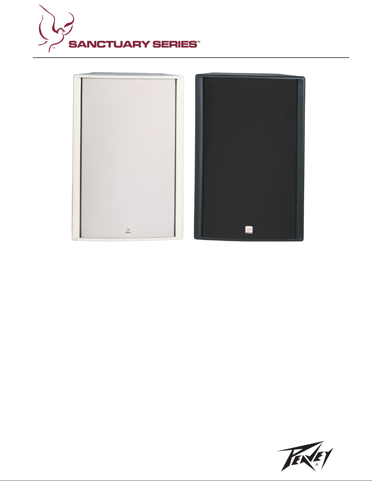
SSE™ 15
SNOITACIFICEPS
Description
The SSE 15 is designed for professional
permanent installations where cabinets
must be own in order to cover as much
area as possible. The SSE 15 is designed
for arraying on stage, churches
auditoriums or theme parks. The horn has
a coverage pattern of 90˚ in the horizontal
axis and 40˚ in the vertical axis. The highs
are generated using the highly acclaimed
Peavey 14T titanium compression driver.
The Sound Guard IV tweeter protection
network is built in for driver protection.
The low end is produced using the Peavey
15" woofer with 2.5" (64 mm)
voice coil. Connections are made using a
4-pin twist-lock connector or a paralleled
two-position terminal block for additional
cabinets. The SSE 15 incorporates ying
points on the top and bottom for the
utilization of the Peavey VersaMount 70
mounting bracket.
The SSE 15 is constructed with a special
grade of high density 13 mm birch plywood
and covered with a durable acrylic
polyurethane. This nish makes the
enclosure pr
The SSE 15 is available in black or white
nishes. The SSE 15 is engineered for
public address and a wide range of musical
applications.
esentable in
any application.
Features:
• Two-way sound reinforcement
enclosure
• Designed for permanent install
• Full-range, wide-band production
from 74 Hz to 17 kHz
• Available in black or white nishes
• Peavey 15" woofer with
2.5" (64 mm) voice coil
• Peavey 14T™ titanium diaphragm
compression driver
• Sound Guard™ IV tweeter
protection network
• Seven ying points (six M10 for
suspension and one M6 for angle
adjustment)
• Mounting point for VersaMount™ 70
bracket
• 13 mm birch plywood construction
Frequency response, 1 meter on-axis,
swept-sine in anechoic environment:
74 Hz to 17 kHz (±3 dB)
Usable low frequency limit (-10 dB
point):
54 Hz
Power handling:
Full range:
500 Watts program
1,000 Watts peak
Sound pressure level, 1 Watt, 1 meter in
anechoic environment:
Full range:
98 dB SPL (2.83 V input)
Maximum sound pressure level
(1 meter):
Full range:
122 dB SPL continuous
128 dB SPL peak
Radiation angle measured at -6 dB
Page 2
point of polar response:
500 Hz to 1.6 kHz:
Horiz. 90˚ ± 20˚
Vert. 95˚ ± 30˚
1.6 kHz to 5 kHz:
Horiz. 70˚ ± 20˚
Vert. 60˚ ± 35˚
5 kHz to 16 kHz:
Horiz. 90˚ ± 15˚
Vert. 40˚ ± 10˚
Directivity factor, Q (Mean):
10.86 ± 6.7
Directivity index, Di (Mean):
9.57 dB ± 2.6 dB
Transducer complement:
Low frequency section:
Peavey Heavy Duty 15” woofer
High frequency section:
Peavey 14T
compression driver on a 90˚ x 40˚
constant directivity horn
™
titanium diaphragm
Box tuning frequency:
Low frequency section:
74 Hz
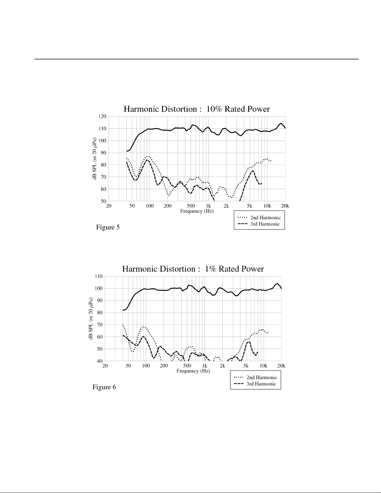
Harmonic distortion:
1% rated power
Second harmonic:
100 Hz: 2.81%
1 kHz: 0.13%
Third harmonic:
100 Hz: 1.0%
1 kHz: 0.18%
10% rated power
Second harmonic:
100 Hz: 8.91%
1 kHz: 0.56%
Third harmonic:
100 Hz: 5.62%
1 kHz: 0.32%
Electro-acoustic crossover frequency
(internal passive):
2.8 kHz
Impedance (Z):
Full range:
Nominal: 8 Ω
Minimum: 5.4 Ω
Input Connection:
One (1) 4-pin twist-lock connector in
parallel with one (1) two-position
terminal strip
Trapezoidal, dado-joined 13 mm birch
polyurethane. Also includes a full-length
metal grille covered with acoustical
grade grille cloth. Available in black
or white nishes.
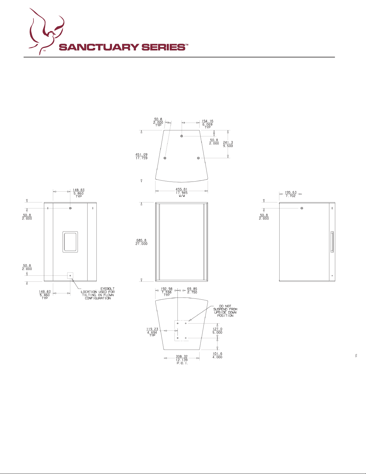
Mounting provisions:
(6) M10 threaded mounting
suspension points (three each top and
one each side and back). Use only
forged shoulder machinery eye bolt,
DIN 580, ASTM A489, or BGV-C1 spec.
(1)
M6 x 1.0mm threaded mounting point
on back bottom for angle adjustments.
(4)
M6 x 1.0mm threaded mounting points
on bottom to accommodate use of
Versamount™ 70 adjustable mounting
bracket.
DO NOT suspend this unit upside down
using VersaMount™ system.
Dimensions (H x W x D):
Front:
27" x 18" x 17.75"
686 mm x 467 mm x 451 mm
Rear:
27" x 12.14" x 17.75"
686 mm x 308 mm x 451 mm
Net Weight:
42 lbs. (19 kg)
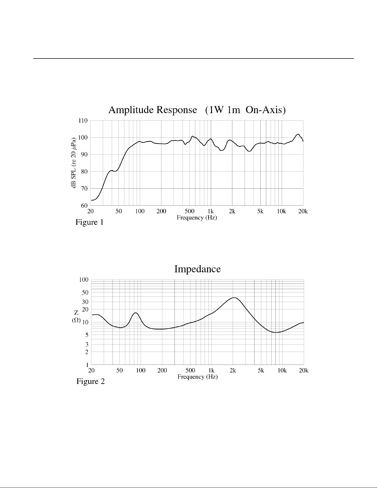
Frequency response
This measurement is useful in determining
how accurately a given unit reproduces an
input signal. The frequency response of
the SSE 15 is measured at a distance of 1
meter using a 1 Watt (into the nominal
impedance) swept-sine input signal. As
the SSE 15 combine to give a smooth
frequency response from 74 Hz to 17 kHz.
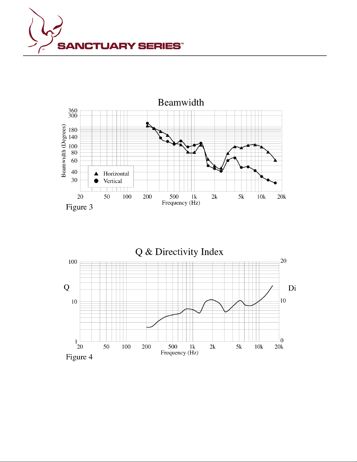
Directivity
Beamwidth is derived from the -6 dB
which are measured in a whole-space
anechoic environment. Q and Directivity
Index are plotted for the on-axis
measurement position. These are
the coverage characteristics of the unit.
These parameters provide insight for
proper placement and installation in the
chosen environment. The blending of the
components of the SSE 15 exhibit a
desirable beamwidth and directivity
reinforcement applications.
Power handling
power handling ratings. Peavey rates this
loudspeaker system’s
using a full-range form of the AES
Standard 2-1984. Using audio band 20 Hz
to 20 kHz pink noise with peaks of four
times the RMS level, this strenuous test
signal assures the user that every portion
of this system can withstand today’s high
technology music. This rating is contingent
upon having a minimum of 3 dB of
power handling
Harmonic distortion
Second and third harmonic distortions vs.
two power levels. Ten percent (10%) of
rated input power and either one percent
(1%) of rated input power or 1 Watt,
whichever is greater. Distortion is read
the fundamental signal (frequency
response) and the desired harmonic. As an
example, a distortion curve that is down
40 dB from the fundamental is equivalent
to 1% distortion.
Mounting
Caution: Before attempting to suspend or
structural engineer. The speaker may fall
due to improper installation, resulting in
serious injury and property damage. DO
NOT suspend or mount any other product
or device from this enclosure. Maximum
enclosure angle 45˚. Use only Grade 8.8 Metric
hardware or better. All associated rigging
is the responsibility of others.
Architectural and Engineering
The loudspeaker system shall have an
operating bandwidth of 74 Hz to 17 kHz.
The nominal output level shall be 98 dB
when measured at a distance of one meter
with an input of one Watt. The nominal
impedance shall be 8 Ohms. The maximum
program power handling shall be 500
Watts with a peak power input of at least
headroom of 3 dB. The nominal radiation
geometry shall be 90˚ in the horizontal
plane and 40˚ in the vertical plane. The
outside dimensions shall be 27" high by
18" wide by 17.75" deep. The weight shall
be 42 lbs. The loudspeaker system shall
be a SSE 15 model.
NOTE:
change without notice.
WARRANTY INFORMATION AVAILABLE ONLINE
2
Page 3
SPECIFICATIONS
SSE™ 15
3
Page 4
4
Page 5
SPECIFICATIONS
SSE™ 15
5
Page 6
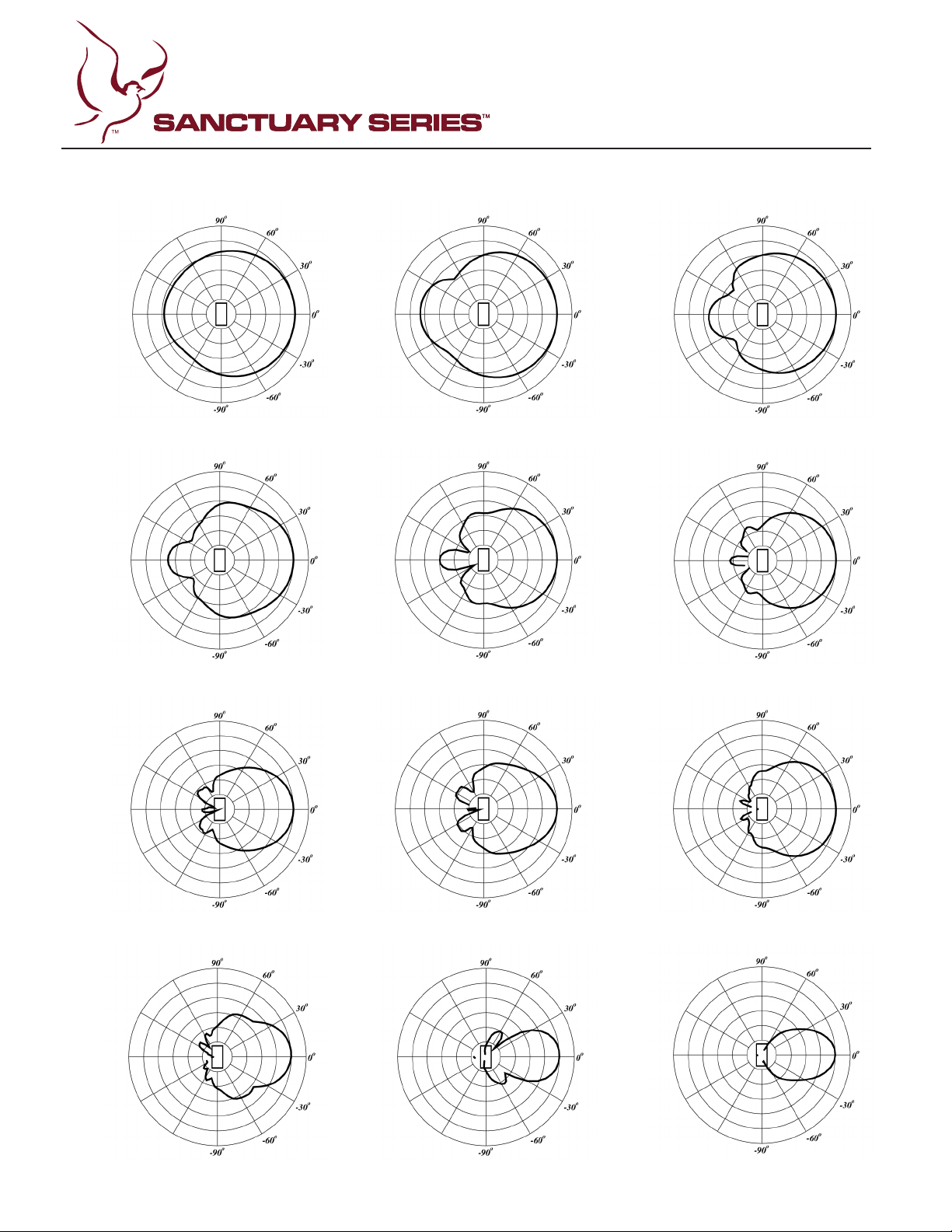
Vertical Polar Patterns 6 dB per Division
200 Hz
400 Hz
250 Hz
500 Hz
315 Hz
630 Hz
800 Hz
1.6 kHz
6
1 kHz
2 kHz
1.25 kHz
2.5 kHz
Page 7
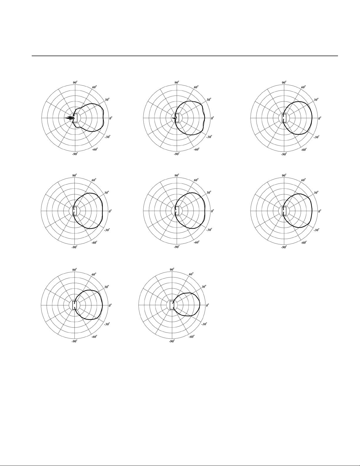
Vertical Polar Patterns 6 dB per Division
SPECIFICATIONS
SSE™ 15
3.15 kHz
6.3 kHz
4 kHz
8 kHz
5 kHz
10 kHz
12.5 kHz
16 kHz
7
Page 8
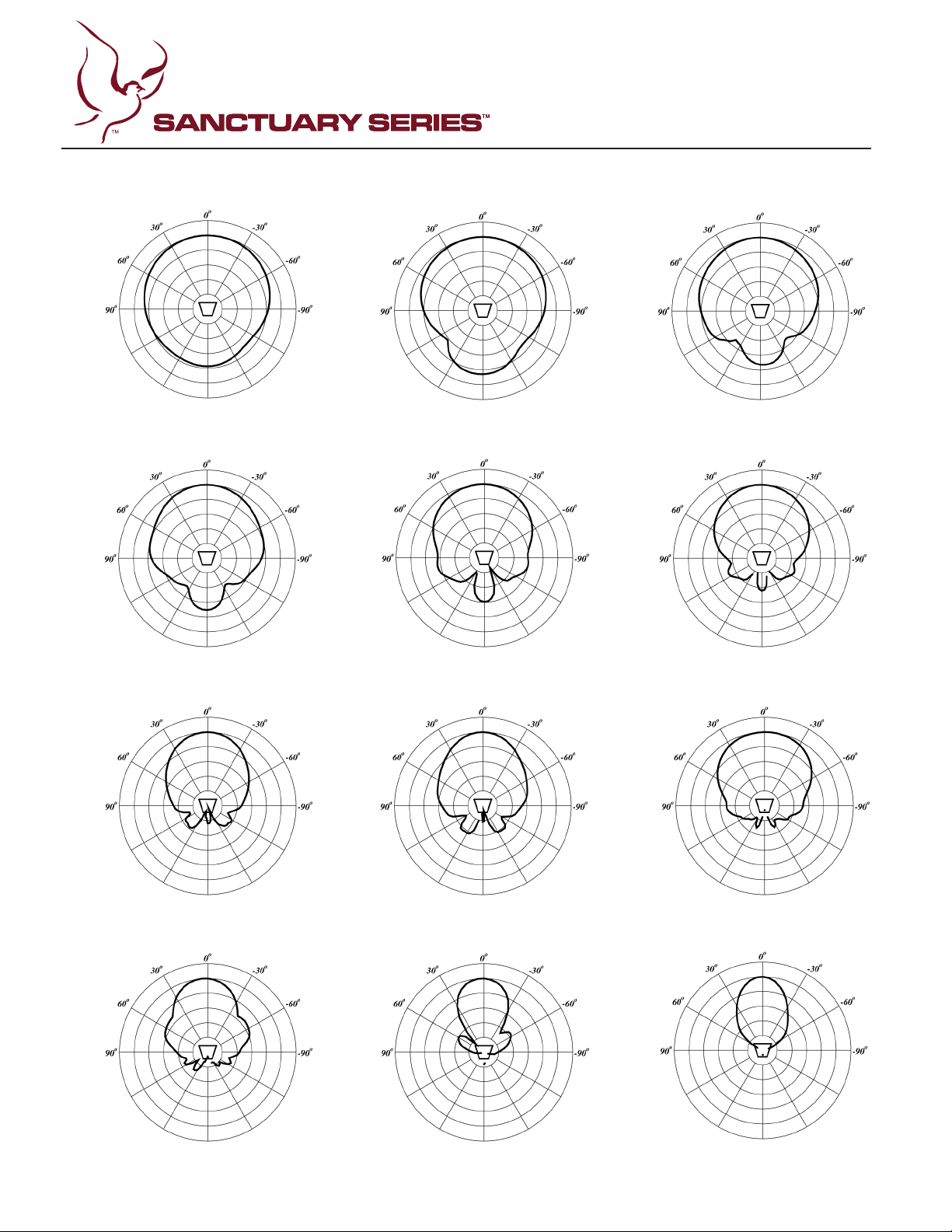
Horizontal Polar Patterns 6 dB per Division
200 Hz
400 Hz
250 Hz
500 Hz
315 Hz
630 Hz
800 Hz
1.6 kHz
8
1 kHz
2 kHz
1.25 kHz
2.5 kHz
Page 9
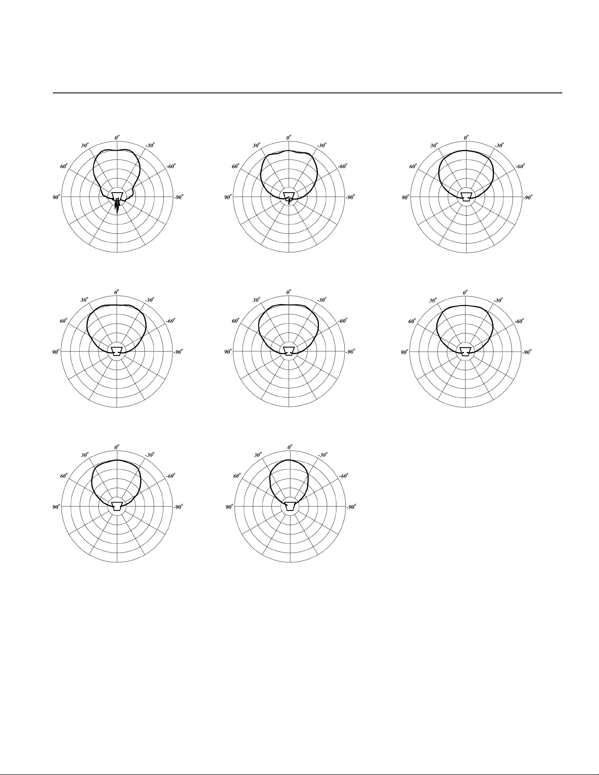
Horizontal Polar Patterns 6 dB per Division
SPECIFICATIONS
SSE™ 15
3.15 kHz
6.3 kHz
4 kHz
8 kHz
5 kHz
10 kHz
12.5 kHz
16 kHz
9
Page 10
10
M6-1.0
Page 11
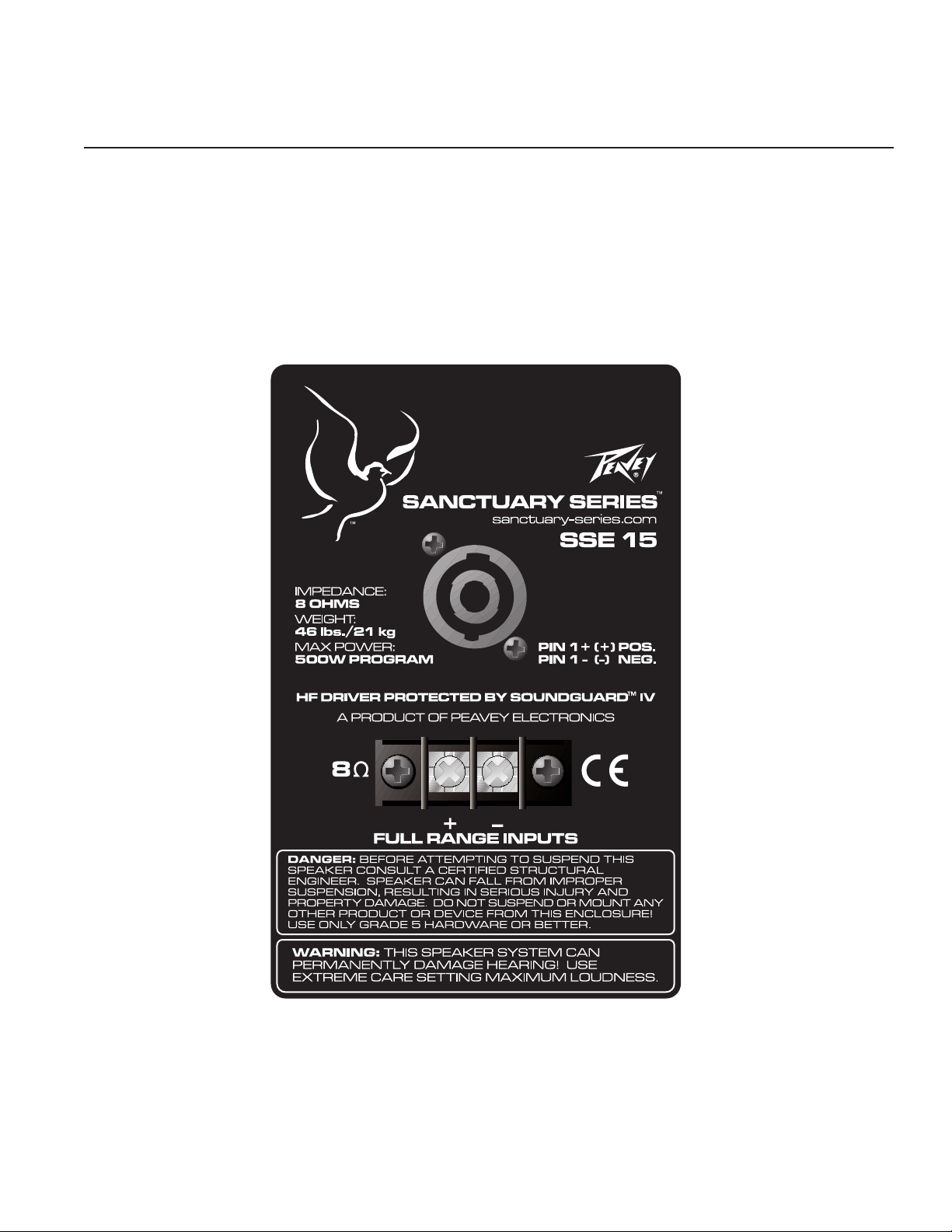
Input Plate
SSE™ 15
SNOITACIFICEPS
MADE IN CHINA
11
Page 12

Logo referenced in Directive 2002/96/EC Annex IV
The bar is the symbol for marking of new waste and
13 August 2005
Flying/Rigging Information
C
aution: Before attempting to suspend this speaker, consult a certified structural engineer. Speaker can fall from improper
suspension, resulting in serious injury and property damage. Do not suspend or mount any other product or device from
his enclosure! Maximum enclosure angle 30°. Use only the correct mating hardware. All associated rigging is the
t
r
esponsibility of others. DO NOT OVER TORQUE HARDWARE. ALWAYS USE SAFETY CHAIN. INSPECT RIGGING
ANNUALLY.
Hardware for Flying/Rigging
Bracket bolts should be metric thread grade 8.8 or better. Eyebolts and bracket bolts must conform to certain minimum
strength criteria for safety reasons. Unspecified eyebolts found at local hardware stores are not strong enough to maintain
fety for overhead flying or rigging. Use only forged steel shoulder machinery eyebolts designed for rigging use. Eyebolts
sa
should comply to one of the following standards: DIN 580, ASTM A489, or the German BGV-C1 specification. This Peavey
l
oudspeaker should be suspended overhead only in accordance with the procedures and limitations specified in this User’s
Manual and possible manual update notices. This system should be suspended with certified rigging hardware by an
authorized rigging professional and in compliance with local, state and federal suspension ordinances.
Warranty registration and information for U.S. customers available online at
Peavey Electronics Corporation 5022 Hartley Peavey Drive Meridian, MS 39305 (601) 483-5365 FAX (601) 486-1278
www.peavey.com
www.peavey.com/warranty
or use the QR tag below
Features and specications subject to change without notice.
(OJ(L)37/38,13.02.03 and defined in EN 50419: 2005
is applied only to equipment manufactured after
 Loading...