

Page 1
SPECIFICATIONS
Features
• Four zone presets
• 5-pin XLR low-Z mic input
Electronically balanced
• Mic level control +25 dBu full
scale
• Electronically balanced output
Applications
• Transportation Centers
• Convention Centers
• Theme Parks
• Industrial Plants
• Medical Centers
• High Rise Facilities
• Research Facilities
• Hotels and Resorts
• Casinos
Operation
5 LED color indicates status of each of
the four zone presets.
5 Green indicates the zone is
available and not in use by
another station.
5 Red indicates the zone is in
use.
5 When the microphone “Talk” button is
pressed, the selected zone preset
LED turns orange to confirm that it is
active. Other stations connected to the
system will indicate RED to confirm that
this particular zone is in use.
5 Press any zone preset button to select.
The LED will blink, confirming the
selection.
5 At power-up, the unit defaults to zone
one, and after one minute of inactivity
reverts back to zone one.
5 Hand-held 5-pin mic input is activated
by pressing the “talk” button.
5 Zone presets can be labeled in the
appropriate white boxes.
5 If all LEDs flash red at power-up, this is
an indication that the station has not
been programmed.
5 If all LEDs flash green at power-up, this
is an indication that the station has
been programmed.
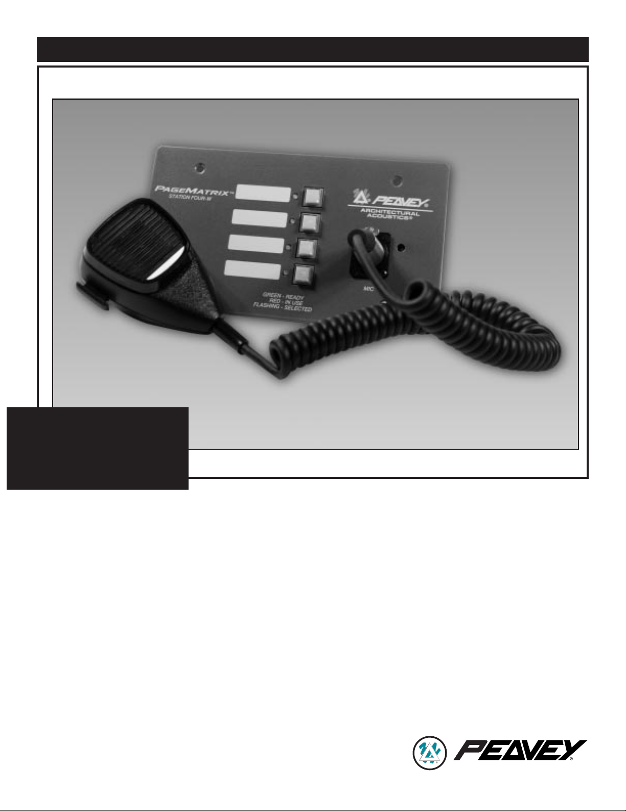
ARCHITECTURAL ACOUSTICS
®
PAGEMATRIX
™
STATION 4-W
Page 2
Specifications
Maximum Input Level:
-22 dBu
Maximum Output Level:
+25 dBu
Input Impedance:
2.2K Ohms
Output Impedance:
200 Ohms
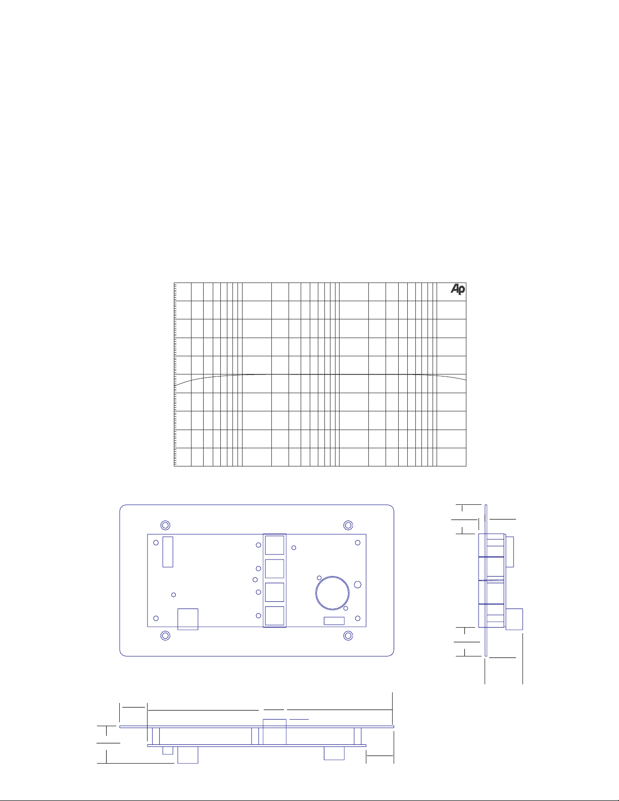
Frequency Response:
20 Hz to 20 kHz (+0, -2 dB)
Phantom Power:
+48V DC
Signal-to-Noise Ratio:
Greater than 88 dB
Power Requirements:
48mA at +24V DC
Total Harmonic Distortion:
Less than 0.01% at 1 kHz
Dimensions:
4.5" H x 8.2" W x 1" D
11.43cm x 20.82cm x 2.54cm
Architectural and
Engineering Specifications
The Station Four-W shall have four
momentary non-programmable buttons.
Programming for these buttons shall occur
at the PageMatrix Controller and in the
MediaMatrix pasha.ini file and view file.
The buttons shall light up when pressed,
or have a multi function LED beside them
indicating "Ready" status. An indicator
shall also be present, indicating a “Zone
Busy” status. The multi function LED can
also serve as the “Busy” indicator. The
unit shall have a 5-pin XLR connector on
the front panel for a keyed microphone,
three pins for audio, and two pins for the
keyed mic closure. The closure of the
"keyed mic" shall be integral to the final
paging function and shall also act as a
release for the current zone requested.
The unit shall have a microphone preamplifier and supply +48V phantom power to
the mic. The unit shall communicate to the
PageMatrix Controller via CATEGORY 5
cable that carries DC power, line level
audio, and the RS-485 serial data.
Frequency Response
Mechanical Diagram
2
+10
+8
+6
+4
+2
d
-0
B
-2
-4
-6
-8
-10
20 20k50 100 200 500 1k 2k 5k 10k
Hz
.858"
21.793cm
.190
4.826cm
1.122"
28.499cm
.828"
21.031cm
4.826cm
.190"
.858"
.828"
21.031cm
21.793cm
1.122"
28.499cm
Page 3
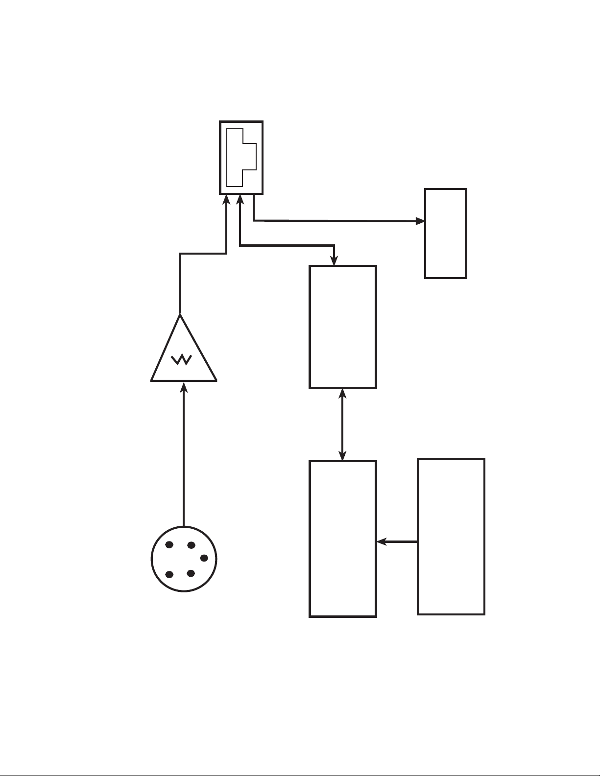
MIC PREAMP
PAGEMATRIX
™
STATION 4-W BLOCK DIAGRAM
3
RJ45 JACK
RS-485
TRANSCEIVER
POWER
+24V DC
5-PIN XLR
Mic INPUT
MICROPROCESSOR
ZONE 1-4 SWITCHES
Page 4

Wiring Diagrams
5-Pin Plug to Mic
5-Pin Connector Mic
1 Audio Shield
2 Audio +
3 Audio 4 Mic Switch
5 GND
8 Position DIP Switch
Reference number: SW 200
Positions: All 8 OFF
4
Cat 5 Plug
8 7 6 5 4 3 2 1
Back View of PCB
LineOut -
LineOut +
GND {Shield}
GND
SWITCHES
ALL 8 OFF
DIP
485+
485-
GND
+24V
RJ45 JACK
Page 5

Características
• Cuatro zonas preprogramadas
• Entrada de micrófono auxiliar XLR de
cinco terminales, equilibrada
electrónicamente
• Control de nivel de micrófono de
+25 dBu a plena escala
• Salida equilibrada electrónicamente
Aplicaciones
• Centros de transporte
• Centros de convenciones
• Parques temáticos
• Plantas industriales
• Centros médicos
• Servicios públicos en edificios de varios
pisos
• Instalaciones de investigación
• Hoteles y centros de recreación
• Casinos
Operación
▲ El color del LED indicador muestra el
estado de cada una de las zonas
preprogramadas:
▲ El color verde indica que la
zona está disponible.
▲ El color rojo indica que la zona
está siendo utilizada.
▲ Cuando se oprime el pulsador “Hablar”
del micrófono, el LED indicador de la
zona preprogramada pasa a color
naranja para confirmar que dicha zona
está activa. Las otras estaciones
conectadas al sistema se indican con
color rojo, para confirmar que la zona
preprogramada está siendo utilizada.
▲ Para seleccionar, oprima cualquier
botón de zona preprogramada. El LED
indicador destellará para confirmar la
selección.
▲ Al encender el sistema, la estación, por
defecto, selecciona la zona uno y
después de un minuto de inactividad en
otra zona, vuelve a la zona uno.
▲ La entrada del micrófono de cinco
terminales se activa oprimiendo el
pulsador “Hablar”.
▲ Las zonas preprogramadas se pueden
rotular en las casillas de color blanco
correspondientes.
▲ Si todos los LED indicadores destellan
con color rojo al encender el sistema,
significa que la estación no ha sido
programada.
▲ Si todos los LED indicadores destellan
con color verde al encender el sistema,
significa que la estación ha sido
programada.
Especificaciones
Nivel de entrada máximo:
–22 dBu
Nivel de salida máximo:
+25 dBu
Impedancia de entrada:
2,2 KW
Impedancia de salida:
200 W
Respuesta de frecuencia:
20 Hz a 20 kHz (+0, –2 dB)
Alimentación fantasma:
+48 VCC
Relación señal/ruido:
Mayor que 88 dB
Requisitos de alimentación:
48 mA a +24 VCC
Distorsión armónica total:
Menor que 0,01% a 1 kHz
Dimensiones:
11,43 x 20,82 x 2,54 cm
(alto x ancho x prof.)
Especificaciones de
arquitectura e ingeniería
La Station Four-W (estación de pared
de cuatro botones) tiene cuatro
pulsadores no programables. La
programación de esos pulsadores se
efectúa en el controlador PageMatrix, en
los archivos pasha.ini y view del software
MediaMatrix. Los botones se iluminan
al oprimirlos o tienen un LED indicador
multifunción al lado de ellos para indicar
el estado “Listo”. También hay presente
un indicador para indicar el estado “Zona
ocupada”. El LED indicador multifunción
también sirve como indicador de
"Ocupada". La unidad tiene un conector
XLR de cinco terminales en el panel
frontal para un micrófono con pulsador
(tres terminales para audio y dos para
cerrar el circuito del micrófono con
pulsador). El cierre del circuito del
micrófono con pulsador está integrado con
la función de intercomunicación final y
también acciona como liberador de la
zona actualmente requerida. La unidad
tiene un preamplificador de micrófono y
suministra +48 V de alimentación
fantasma para el micrófono. La unidad
se comunica con el controlador
PageMatrix mediante un conector tipo
RJ45. El cable de comunicaciones
CATEGORÍA5 transporta la alimentación
de CC, la señal de audio con nivel de
línea y los datos del conector en serie
RS-485.
ESTACIÓN DE PARED DE CUATRO BOTONES
ESPAÑOL
5
Page 6

Caractéristiques
• Quatre présélections de zone
• Entrée de microphone basse impédance
XLR à 5 broches symétrique
• Commande de niveau microphone
+25 dBu pleine échelle
• Sortie symétrique
Applications
• Centres de transport
• Centres de congrès
• Parcs à thème
• Usines
• Centres médicaux
• Grands immeubles
• Centres de recherches
• Hôtels et centres de villégiature
• Casinos
Fonctionnement
▲ La couleur du voyant DEL indique l’état
de chacune des quatre présélections de
zone.
▲ La couleur verte indique que la
zone est libre.
▲ La couleur rouge indique que
la zone est occupée.
▲ Lorsque le bouton d’alternat du
microphone est enfoncé, la DEL de la
zone présélectionnée devient orange
pour indiquer qu’elle est active. Les DEL
des autres postes reliés au système
s’allument en ROUGE pour indiquer que
la présélection de zone est en usage.
▲ Appuyez sur la touche de n’importe
quelle zone pour la sélectionner. Sa
DEL clignote pour confirmer la sélection.
▲ À la mise sous tension et au bout d’une
minute d’inactivité, l’appareil passe
automatiquement à la zone 1 (défaut).
▲ L’entrée à 5 broches du microphone à
main est activée en appuyant sur le
bouton d’alternat du microphone.
▲ Les présélections de zone peuvent être
identifiées dans les cases blanches
appropriées.
▲ Si toutes les DEL clignotent en rouge
lors de la mise sous tension, cela
signifie que le poste n’a pas été
programmé.
▲ Si toutes les DEL clignotent en vert lors
de la mise sous tension, cela signifie
que le poste a été programmé.
Caractéristiques
Niveau d’entrée maximum:
-22 dBu
Niveau de sortie maximum:
+25 dBu
Impédance d’entrée:
2,2 kiloohms
Impédance de sortie:
200 ohms
Réponse en fréquence:
20 Hz à 20 kHz (+0, -2 dB)
Alimentation duplex:
+48 V c.c.
Rapport signal/bruit:
Supérieur à 88 dB
Alimentation:
48 mA à +24 V c.c.
Distorsion harmonique totale:
Moins de 0,01 % à 1 kHz
Dimensions:
4,5 po H x 8,2 po L x 1 po P
11,43 cm x 20,82 cm x 2,54 cm
Spécifications architecturales
et techniques
Le modèle Station Four-W doit comporter
quatre touches à action momentanée non
programmables. La programmation de
ces touches doit se faire au niveau du
contrôleur PageMatrix ainsi que dans
le fichier pasha.ini et le fichier de
visualisation du logiciel MediaMatrix.
Ces touches doivent s’allumer lorsqu’elles
sont enfoncées ou être dotées d’une DEL
multifonctions indiquant l’état « prêt ». Un
témoin doit également être présent pour
indiquer l’état de « zone occupée ». La
DEL multifonctions peut également servir
de témoin « occupé ». Le panneau
avant de l’appareil doit être doté d’un
connecteur XLR à 5 broches pour
microphone à « clé », trois broches étant
utilisées pour le signal audio et deux pour
la fermeture du microphone. La fermeture
du « microphone à clé » doit faire partie
intégrante de la fonction de dernier appel
et commander la libération de la zone en
cours d’utilisation. L’appareil doit être doté
d’un préamplificateur de microphone
et d’une alimentation duplex de +48 V
pour ce microphone. L’appareil doit
communiquer avec le contrôleur
PageMatrix via un câble de
communications CATÉGORIE 5
porteur du courant d’alimentation c.c.,
du signal audio de niveau ligne et des
données série RS485.
POSTE FOUR-W
FRANÇAIS
6
Page 7

Merkmale
• Vier Zonenvoreinstellungen
• 5-Pin-XLR-Mikrofoneingang
“Low-Z” Elektronischer Abgleich
• Mikrofonregler +25 dBu Full-Scale
• Ausgang mit elektronischem Abgleich
Einsatzbereiche
• Flughäfen, Bahnhöfe, Reisezentren
• Kongreßzentren
• Ausstellungen und Vergnügungsparks
• Fabriken
• Kliniken
• Hochhäuser
• Forschungszentren
• Hotels, Erholungs- und Kuranlagen
• Kasinos
Funktionsprinzip
▲ Die Leuchtdiodenfarbe gibt den Status
der jeweiligen Voreinstellzone wieder
▲ Grün bedeutet, daß die Zone
frei ist, d.h. nicht von einer
anderen Station gerufen wird.
▲ Rot bedeutet, daß die Zone
belegt ist.
▲ Drückt man auf die Sprechtaste des
Mikrofons, wird die gewählte Zonentaste
orange und bestätigt damit die
Aktivierung. Andere am System
angeschlossene Stationen zeigen die
entsprechende Zonentaste ROT an und
signalisieren damit, daß die Zone belegt
ist.
▲ Zum Wählen einer Zone drückt man auf
die entsprechende Taste. Zur
Bestätigung der Wahl blinkt die
Leuchtdiode.
▲ Beim Einschalten sowie nach
einminütiger Inaktivität schaltet das
Gerät automatisch auf Zone eins um.
▲ Der fünfpolige Eingang des
Handmikrofons wird durch Drücken der
Sprechtaste (“Talk”) aktiviert.
▲ Zum Beschriften der Voreinstellzonen
sind weiße Felder vorgesehen.
▲ Wenn alle Leuchtdioden beim
Einschalten rot blinken, bedeutet dies,
daß die Station noch nicht programmiert
ist.
▲ Wenn alle Leuchtdioden beim
Einschalten grün blinken, bedeutet dies,
daß die Station programmiert ist.
Technische Daten
Maximaler Eingangspegel:
-22 dBu
Maximaler Ausgangspegel:
+25 dBu
Eingangsimpedanz:
2,2 KW
Ausgangsimpedanz:
200 W
Frequenzgang:
20 Hz bis 20 kHz (+0, -2 dB)
Phantomspeisung:
+48 V=
Geräuschabstand:
Mehr als 88 dB
Anschlußwerte:
48 mA bei +24 V=
Gesamtklirrfaktor:
Weniger als 0,01 % bei 1 kHz
Abmessungen:
102 mm x 32 mm x
180
mm
(H x B x T)
Architektonische und
technische Beschreibung
Die Station Four-W verfügt über vier nicht
programmierbare, nichtrastende
Momentdrucktaster. Die
Belegungsprogrammierung für diese
Tasten erfolgt über den PageMatrixController sowie die Datei pasha.ini und
die Ansichtsdatei in MediaMatrix. Die
Tasten leuchten auf, wenn sie gedrückt
werden, bzw. haben eine eingebaute
Multifunktions-Leuchtdiode, die den
Bereitschaftsstatus anzeigt. Ferner ist eine
Anzeigelampe zur Signalisierung des
Belegt-Status vorgesehen. Die
Multifunktions-Leuchtdiode kann auch als
Anzeiger für den Belegt-Status fungieren.
An seiner Frontplatte verfügt das Gerät
über einen 5-Pin-XLR-Anschluß für ein
tastenaktiviertes Mikrophon. Drei der
Kontakte sind für die Audiosignale
vorgesehen, zwei weitere für die
Mikrofon-Tastenaktivierung. Der
Kontaktschluß des tastenaktivierten
Mikrofons ist integraler Bestandteil der
Ruffunktion selbst und gibt zugleich die
jeweils angeforderte Zone frei. Das
Gerät ist mit einem Mikrofonvorverstärker
ausgestattet und versorgt das Mikrofon mit
+48V Phantomspannung. Das Gerät
kommuniziert mit dem PageMatrixController über ein Kabel der CATEGORY
5, das den Versorgungs-Gleichstrom, den
Audiosignalpegel und die seriellen Daten
der RS485-Verbindung überträgt.
FOUR-W
DEUTSCH
7
Page 8

3 + 2 YEAR LIMITED WARRANTY
NOTE: For details, refer to the warranty statement. Copies of
this statement may be obtained by contacting
Peavey ElectronicS Corporation
P.O. Box 2898, Meridian, Mississippi 39301-2898.
Features and specifications subject to change without notice.
Peavey Electronics Corporation • 711 A Street • Meridian • MS • 39301
(601) 483-5376 • FAX (601) 486-1678 • www.peavey.com
©1999 Printed in the U.S.A. 3/99
80304512
ARCHITECTURAL ACOUSTICS
®
 Loading...