

Page 1
Features
• Four Zone preset
• 3-pin XLR low-Z mic input
5-pin XLR Aux Mic input
Electronically balanced
• Mic level control +25 dBu full
scale
• Electronically balanced output
Applications
• Transportation Centers
• Convention Centers
• Theme Parks
• Industrial Plants
• Medical Centers
• High Rise Facilities
• Research Facilities
• Hotels and Resorts
• Casinos
Operation
5 LED color indicates status of each of
the four zone presets.
5 Green indicates the zone is
available.
5 Red indicates the zone is in
use.
5 When the microphone “Push to Talk”
button is pressed, the selected zone
preset LED turns orange to confirm that
it is active. Other stations connected to
the system will indicate RED to confirm
that the zone preset is in use.
5 Press any zone preset button to select.
The LED will blink, confirming the
selection.
5 At power-up, the unit defaults to zone
one, and after one minute of inactivity
reverts back to zone one.
5 Hand-held 5-pin mic input is activated
by pressing the “talk” button.
5 Zone presets can be labeled in the
appropriate white boxes.
5 If all LEDs flash red at power-up, this is
an indication that the station has not
been programmed.
5 If all LEDs flash green at power-up, this
is an indication that the station has
beenprogrammed.
5 The Aux mic input (rear panel) is
always routed to zone preset one.
Specifications
Maximum Input Level:
-22 dBu
Maximum Output Level:
+25 dBu
Input Impedance:
2.2K Ohms
Output Impedance:
200 Ohms
Frequency Response:
20 Hz to 20 kHz (+0, -2 dB)
Phantom Power:
+48V DC
Signal-to-Noise Ratio:
Greater than 85 dB
Power Requirements:
55mA at +24V DC
Total Harmonic Distortion:
Less than 0.01% at 1 kHz
Dimensions:
4" H x 5.2" W x 7.1" D
10.16cm x 13.21cm x 18.03cm
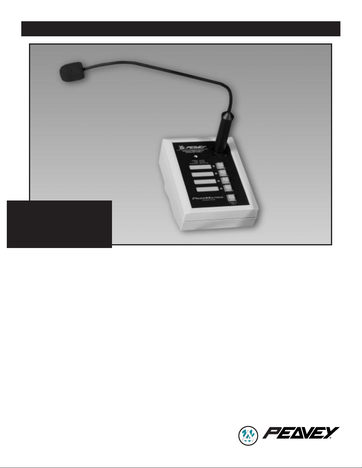
SPECIFICATIONS
PAGEMATRIX
™
STATION
FOUR BUTTON
ARCHITECTURAL ACOUSTICS
®
Page 2
Architectural and
Engineering Specifications
The Station Four shall have four momentary non-programmable buttons.
Programming for these buttons shall occur
at the PageMatrix Controller and in the
MediaMatrix pasha.ini file and view file.
The buttons shall light up when pressed,
or have a multi function LED beside them
indicating ÒReadyÓ status. An indicator
shall also be present, indicating a ÒZone
BusyÓ status. The multi function LED can
also serve as the ÒBusyÓ indicator. The
unit shall have a 3-pin XLR connector on
the front panel for audio. The unit shall
have a 5-pin XLR connector on the back
panel for a keyed microphone, three pins
for audio, and two pins for the Òkeyed micÓ
closure. The closure of the Òkeyed micÓ
shall be integral to the final paging
function and shall also act as a release
for the current zone requested. The unit
shall have a microphone preamplifier and
supply +48V phantom power to the mic.
The unit shall communicate to the
PageMatrix Controller via RJ45 style
connector. The communications cable
CATEGORY 5 carries DC power, line
level audio, and the RS485 serial data.
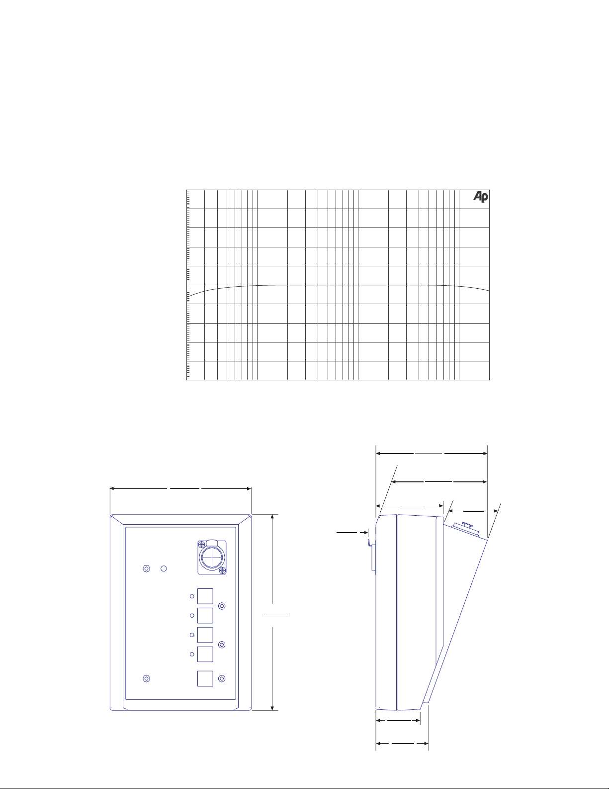
Frequency Response
Mechanical Diagram
2
+10
+8
+6
+4
+2
d
-0
B
-2
-4
-6
-8
-10
20 20k50 100 200 500 1k 2k 5k 10k
Hz
4.040"
10.26cm
5.123"
13.01cm
7.086"
18.0cm
.274"
.70cm
2.449"
6.22cm
10.14cm
3.993"
1.693"
4.30cm
1.607"
4.08cm
1.908"
4.85cm
Page 3
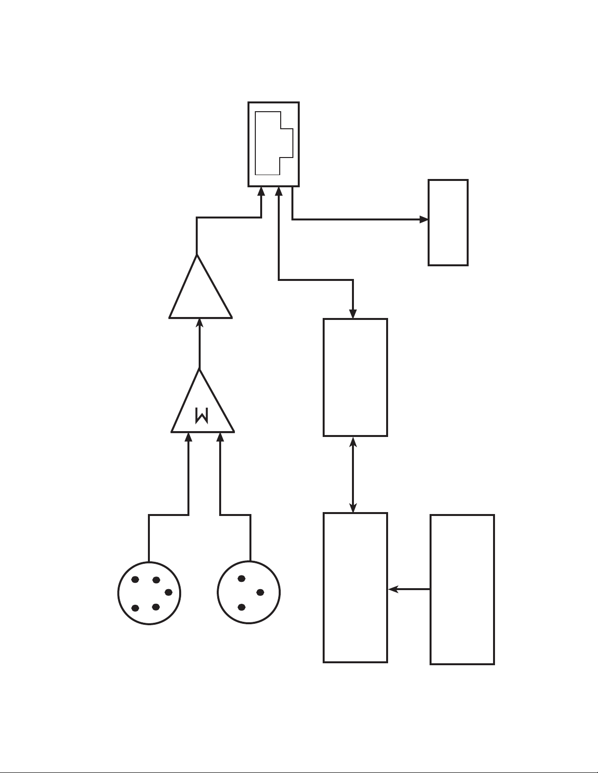
PREAMP
PAGEMATRIX
ª
STATION FOUR BLOCK DIAGRAM
3
MIC
SUMMER
RJ45 JACK
RS-485
TRANSCEIVER
POWER
+24V DC
5-PIN XLR
AUX MIC INPUT
3-PIN XLR
MIC INPUT
MICROPROCESSOR
ZONE 1-4 SWITCHES
Page 4

Wiring Diagrams
5-Pin Plug to Mic
5-Pin Connector Mic
1 Audio Shield
2 Audio +
3 Audio 4 Mic Switch
5 GND
4
8 7 6 5 4 3 2 1
LineOut -
LineOut +
GND {Shield}
GND
Cat 5 Plug
485+
485-
GND
+24V
Page 5

Caracter’sticas
¥ Cuatro zonas preprogramadas
¥ Entrada de micr—fono de baja
impedancia XLR de tres terminales
Entrada de micr—fono auxiliar XLR
de cinco terminales, equilibrada
electr—nicamente
¥ Control de nivel de micr—fono de
+25 dBu a plena escala
¥ Salida equilibrada electr—nicamente
Aplicaciones
¥ Centros de transporte
¥ Centros de convenciones
¥ Parques tem‡ticos
¥ Plantas industriales
¥ Centros mŽdicos
¥ Servicios pœblicos en edificios de varios
pisos
¥ Instalaciones de investigaci—n
¥ Hoteles y centros de recreaci—n
¥ Casinos
Operaci—n
▲ El color del LED indicador muestra el
estado de cada una de las zonas
preprogramadas:
▲ El color verde indica que la
zona est‡ disponible.
▲ El color rojo indica que la zona
est‡ siendo utilizada.
▲ Cuando se oprime el pulsador ÒHablarÓ
del micr—fono, el LED indicador de la
zona preprogramada pasa a color
naranja, para confirmar que dicha zona
est‡ activa. Las otras estaciones
conectadas al sistema se indican con
color rojo, para confirmar que la zona
preprogramada est‡ siendo utilizada.
▲ Para seleccionar, oprima cualquier
bot—n de zona preprogramada. El LED
indicador destellar‡ para confirmar la
selecci—n.
▲ Al encender el sistema, la estaci—n, por
defecto, selecciona la zona uno y
despuŽs de un minuto de inactividad en
otra zona, vuelve a la zona uno.
▲ La entrada del micr—fono de cinco
terminales se activa oprimiendo el
pulsador ÒHablarÓ.
▲ Las zonas preprogramadas se pueden
rotular en las casillas de color blanco
correspondientes.
▲ Si todos los LED indicadores destellan
con color rojo al encender el sistema,
significa que la estaci—n no ha sido
programada.
▲ Si todos los LED indicadores destellan
con color verde al encender el sistema,
significa que la estaci—n ha sido
programada.
▲ La entrada de micr—fono auxiliar (panel
posterior), siempre se deriva a la zona
preprogramada uno.
Especificaciones
Nivel de entrada m‡ximo:
Ð22 dBu
Nivel de salida m‡ximo:
+25 dBu
Impedancia de entrada:
2,2 KW
Impedancia de salida:
200 W
Respuesta de frecuencia:
20 Hz a 20 kHz (+0, Ð2 dB)
Alimentaci—n fantasma:
+48 VCC
Relaci—n se–al/ruido:
Mayor que 85 dB
Requisitos de alimentaci—n:
55 mA a +24 VCC
Distorsi—n arm—nica total:
Menor que 0,01% a 1 kHz
Dimensiones:
10,16 x 13,21 x 18,03 cm
(alto x ancho x prof.)
Especificaciones de
arquitectura e ingenier’a
El sistema Station Four (estaci—n de
mesa de cuatro botones) tiene cuatro
pulsadores no programables. La
programaci—n de esos pulsadores se
efectœa en el controlador PageMatrix,
en los archivos pasha.ini y view del
software MediaMatrix. Los botones se
iluminan al oprimirlos o tienen un LED
indicador multifunci—n al lado de ellos
para indicar el estado ÒListoÓ. TambiŽn
hay presente un indicador para indicar
el estado ÒZona ocupadaÓ. El LED
indicador multifunci—n tambiŽn sirve
como indicador de ÒOcupadaÓ. La unidad
tiene un conector XLR de tres terminales
para audio en el panel frontal y un
conector XLR de cinco terminales en
el panel trasero para un micr—fono con
pulsador (tres terminales para audio y
dos para cerrar el circuito del micr—fono
con pulsador). El cierre del circuito del
micr—fono con pulsador est‡ integrado
con la funci—n de intercomunicaci—n final
y tambiŽn acciona como liberador de la
zona actualmente requerida. La unidad
tiene un preamplificador de micr—fono
y suministra +48 V de alimentaci—n
fantasma para el micr—fono. La unidad
se comunica con el controlador
PageMatrix mediante un conector tipo
RJ45. El cable de comunicaciones
CATEGORêA 5 transporta la alimentaci—n
de CC, la se–al de audio con nivel de
l’nea y los datos del conector en serie
RS-485.
ESPA„OL
ESTACIÓN DE MESA DE CUATRO BOTONES:
5
Page 6

FRAN‚AIS
POSTE STATION FOUR
CaractŽristiques
¥ Quatre prŽsŽlections de zone
¥ EntrŽe microphone basse impŽdance
XLR ˆ 3 broches et entrŽe microphone
auxiliaire XLR ˆ 5 broches symŽtriques
¥ Commande de niveau microphone
+25 dBu pleine Žchelle
¥ Sortie symŽtrique
Applications
¥ Centres de transport
¥ Centres de congr•s
¥ Parcs ˆ th•me
¥ Usines
¥ Centres mŽdicaux
¥ Grands immeubles
¥ Centres de recherches
¥ H™tels et centres de villŽgiature
¥ Casinos
Fonctionnement
▲ La couleur du voyant DEL indique
lÕŽtat de chacune des quatre
prŽsŽlections de zone.
▲ La couleur verte indique que la
zone est libre.
▲ La couleur rouge indique que
la zone est occupŽe.
▲ Lorsque le bouton dÕalternat du
microphone est enfoncŽ, la DEL de la
zone prŽsŽlectionnŽe devient orange,
pour indiquer quÕelle est active. Les DEL
des autres postes reliŽs au syst•me
sÕallument en ROUGE pour indiquer que
la prŽsŽlection de zone est en usage.
▲ Appuyez sur la touche de nÕimporte
quelle zone pour la sŽlectionner. Sa
DEL clignote pour confirmer la sŽlection.
▲ Ë la mise sous tension et au bout dÕune
minute dÕinactivitŽ, lÕappareil passe
automatiquement ˆ la zone 1 (dŽfaut).
▲ LÕentrŽe ˆ 5 broches du microphone ˆ
main est activŽe en appuyant sur le
bouton dÕalternat du microphone.
▲ Les prŽsŽlections de zone peuvent •tre
identifiŽes dans les cases blanches
appropriŽes.
▲ Si toutes les DEL clignotent en rouge
lors de la mise sous tension, cela
signifie que le poste nÕa pas ŽtŽ
programmŽ.
▲ Si toutes les DEL clignotent en vert lors
de la mise sous tension, cela signifie
que le poste a ŽtŽ programmŽ.
▲ LÕentrŽe de microphone auxiliaire
(panneau arri•re) est toujours
acheminŽe vers la zone de prŽsŽlection
un.
CaractŽristiques
Niveau dÕentrŽe maximum:
-22 dBu
Niveau de sortie maximum:
+25 dBu
ImpŽdance dÕentrŽe:
2,2 kiloohms
ImpŽdance de sortie:
200 ohms
RŽponse en frŽquence:
20 Hz ˆ 20 kHz (+0, -2 dB)
Alimentation duplex:
+48 V c.c.
Rapport signal/bruit:
SupŽrieur ˆ 85 dB
Alimentation:
55 mA ˆ +24 V c.c.
Distorsion harmonique totale:
Moins de 0,01 % ˆ 1 kHz
Dimensions:
4 po H x 5,2 po L x 7,1 po P
10,16 cm x 13,21 cm x 18,03 cm
SpŽcifications architecturales
et techniques
Le mod•le Station Four doit comporter
quatre touches ˆ action momentanŽe non
programmables. La programmation de ces
touches doit se faire au niveau du contr™leur PageMatrix ainsi que dans le fichier pasha.ini et le fichier de visualisation du
logiciel MediaMatrix. Ces touches doivent
sÕallumer lorsquÕelles sont enfoncŽes ou
•tre dotŽes dÕune DEL multifonctions indiquant lÕŽtat Ç pr•t È. Un tŽmoin doit Žgalement •tre prŽsent pour indiquer lÕŽtat de Ç
zone occupŽe È. La DEL multifonctions
peut Žgalement servir de tŽmoin Ç occupŽ
È. Le panneau avant de lÕappareil doit
comporter un connecteur audio XLR ˆ 3
broches pour le signal audio. Le panneau
arri•re doit •tre dotŽ dÕun connecteur XLR
ˆ 5 broches pour microphone ˆ Ç clŽ È,
trois broches Žtant utilisŽes pour le signal
audio et deux pour la fermeture du microphone. Cette fermeture du Ç microphone ˆ
clŽ È doit faire partie intŽgrante de la fonction de dernier appel et commander la
libŽration de la zone en cours dÕutilisation.
LÕappareil doit •tre dotŽ dÕun prŽamplificateur de microphone et dÕune alimentation
duplex de +48 V pour ce microphone.
LÕappareil doit communiquer avec le contr™leur PageMatrix via un connecteur de
type RJ45. Le c‰ble de communications
CATƒGORIE 5 est porteur du courant
dÕalimentation c.c., du signal audio de
niveau ligne et des donnŽes sŽrie RS485.
6
Page 7

Merkmale
¥ Vier Zonenvoreinstellungen
¥ 3-Pin-XLR-Mikrofoneingang ÒLow-ZÓ
¥ 5-Pin-XLR-Zusatzmikrofoneingang (Aux
Mic)
Elektronischer Abgleich
¥ Mikrofonregler +25 dBu Full-Scale
¥ Ausgang mit elektronischem Abgleich
Einsatzbereiche
¥ FlughŠfen, Bahnhšfe, Reisezentren
¥ Kongre§zentren
¥ Ausstellungen und VergnŸgungsparks
¥ Fabriken
¥ Kliniken
¥ HochhŠuser
¥ Forschungszentren
¥ Hotels, Erholungs- und Kuranlagen
¥ Kasinos
Funktionsprinzip
▲ Die Leuchtdiodenfarbe gibt den Status
der jelweiligen Voreinstellzone wieder:
▲ GrŸn bedeutet, da§ die Zone
frei ist.
▲ Rot bedeutet, da§ die Zone
belegt ist.
▲ DrŸckt man auf die Sprechtaste des
Mikrofons, wird die gewŠhlte Zonentaste
orange und bestŠtigt damit die
Aktivierung. Andere am System
angeschlossene Stationen zeigen die
entsprechende Zonentaste ROT an und
signalisieren damit, da§ die Zone belegt
ist.
▲ Zum WŠhlen einer Zone drŸckt man auf
die entsprechende Taste. Zur
BestŠtigung der Wahl blinkt die
Leuchtdiode.
▲ Beim Einschalten sowie nach
einminŸtiger InaktivitŠt schaltet das
GerŠt automatisch auf Zone eins um.
▲ Der fŸnfpolige Eingang des
Handmikrofons wird durch DrŸcken der
Sprechtaste (ÒTalkÓ) aktiviert.
▲ Zum Beschriften der Voreinstellzonen
sind wei§e Felder vorgesehen.
▲ Wenn alle Leuchtdioden beim
Einschalten rot blinken, bedeutet dies,
da§ die Station noch nicht programmiert
ist.
▲ Wenn alle Leuchtdioden beim
Einschalten grŸn blinken, bedeutet dies,
da§ die Station programmiert ist.
▲ Der Zusatzmikrofoneingang (Aux mic)
an der RŸckwand adressiert immer
Voreinstellzone 1.
Technische Daten
Maximaler Eingangspegel:
-22 dBu
Maximaler Ausgangspegel:
+25 dBu
Eingangsimpedanz:
2,2 KW
Ausgangsimpedanz:
200 W
Frequenzgang:
20 Hz bis 20 kHz (+0, -2 dB)
Phantomspeisung:
+48 V=
GerŠuschabstand:
Mehr als 85 dB
Anschlu§werte:
55 mA bei +24 V=
Gesamtklirrfaktor:
Weniger als 0,01 % bei 1 kHz
Abmessungen:
102 mm x 132 mm x 180 mm (H x B x T)
Architektonische und
technische Beschreibung
Die Station Four verfŸgt Ÿber vier nicht
programmierbare, nichtrastende
Momentdrucktaster. Die
Belegungsprogrammierung fŸr diese
Tasten erfolgt Ÿber den PageMatrixController sowie die Datei pasha.ini und
die Ansichtsdatei in MediaMatrix. Die
Tasten leuchten auf, wenn sie gedrŸckt
werden, bzw. haben eine eingebaute
Multifunktions-Leuchtdiode, die den
Bereitschaftsstatus anzeigt. Ferner ist eine
Anzeigelampe zur Signalisierung des
Belegt-Status vorgesehen. Die
Multifunktions-Leuchtdiode kann auch als
Anzeiger fŸr den Belegt-Status fungieren.
An der Frontplatte des GerŠts befindet
sich eine 3-Pin-XLR-Steckbuchse als
Audioanschlu§. An seiner RŸckwand
verfŸgt das GerŠt Ÿber einen 5-Pin-XLRAnschlu§ fŸr ein tastenaktiviertes
Mikrophon. Drei der Kontakte sind fŸr die
Audiosignale vorgesehen, zwei weitere fŸr
die Mikrofon-Tastenaktivierung. Der
Kontaktschlu§ des tastenaktivierten
Mikrofons ist integraler Bestandteil der
Ruffunktion selbst und gibt zugleich die
jeweils angeforderte Zone frei. Das GerŠt
ist mit einem MikrofonvorverstŠrker
ausgestattet und versorgt das Mikrofon
mit +48V Phantomspannung. Das GerŠt
kommuniziert mit dem PageMatrixController Ÿber einen Steckverbinder des
Typs RJ45. Das Kommunikationskabel
der CATEGORY 5 ŸbertrŠgt den
Versorgungs-Gleichstrom, den
Audiosignalpegel und die Daten der
seriellen RS485-Verbindung.
DEUTSCH
VIERTASTENSTATION
7
Page 8

3 + 2 YEAR LIMITED WARRANTY
NOTE: For details, refer to the warranty statement. Copies of
this statement may be obtained by contacting
Peavey Electronics Corporation
P.O. Box 2898, Meridian, Mississippi 39301-2898.
Features and specifications subject to change without notice.
Peavey Electronics Corporation • 711 A Street • Meridian • MS • 39301
(601) 483-5376 • FAX (601) 486-1678 • www.peavey.com
©1999 Printed in the U.S.A. 1/99
80304513
ARCHITECTURAL ACOUSTICS
®
 Loading...