

Page 1
ARCHITECTURAL ACOUSTICS
O WNER’ S M ANUAL
PAGEM ATRIX
Controller
™
Page 2
Intended to alert the user to the presence of uninsulated Òdangerous voltageÓ within the productÕs
enclosure that may be of sufficient magnitude to constitute a risk of electric shock to persons.
Intended to alert the user of the presence of important operating and maintenance (servicing)
instructions in the literature accompanying the product.
CAUTION: Risk of electrical shock Ñ DO NOT OPEN!
CAUTION: To reduce the risk of electric shock, do not remove cover. No user serviceable parts inside. Refer
servicing to qualified service personnel.
WARNING: To prevent electrical shock or fire hazard, do not expose this appliance to rain or moisture. Before
using this appliance, read the operating guide for further warnings.
Este s’mbolo tiene el prop—sito, de alertar al usuario de la presencia de Ò(voltaje) peligrosoÓ que no tiene
aislamiento dentro de la caja del producto que puede tener una magnitud suficiente como para constituir
riesgo de corrientazo.
Este s’mbolo tiene el prop—sito de alertar al usario de la presencia de instruccones importantes sobre la
operaci—n y mantenimiento en la literatura que viene con el producto.
PRECAUCION: Riesgo de corrientazo Ñ ÁNo abra!
PRECAUCION: Para disminu’r el riesgo de corrientazo, no abra la cubierta. No hay piezas adentro que el usario
pueda reparar. Deje todo mantenimiento a los tŽcnicos calificados.
ADVERTENCIA: Para evitar corrientazos o peligro de incendio, no deje expuesto a la lluvia o humedad este
aparato Antes de usar este aparato, Iea m‡s advertencias en la gu’a de operaci—n.
Ce symbole est utilisŽ pour indiquer ˆ lÕutilisateur la prŽsence ˆ lÕintŽrieur de ce produit de tension nonisolŽe dangereuse pouvant •tre dÕintensitŽ suffisante pour constituer un risque de choc Žlectrique.
Ce symbole est utilisŽ pour indiquer ˆ lÕutilisateur quÕil ou quÕelle trouvera dÕimportantes instructions sur
lÕutilisation et lÕentretien (service) de lÕappareil dans la littŽrature accompagnant le produit.
ATTENTION: Risques de choc Žlectrique Ñ NE PAS OUVRIR!
ATTENTION: Afin de rŽduire le risque de choc Žlectrique, ne pas enlever le couvercle. Il ne se trouve ˆ lÕintŽrieur
aucune pi•ce pouvant •tre reparŽe par lÕutilisateur. Confier IÕentretien ˆ un personnel qualifiŽ.
AVERTISSEMENT: Afin de prŽvenir les risques de dŽcharge Žlectrique ou de feu, nÕexposez pas cet appareil ˆ la
pluie ou ˆ lÕhumiditŽ. Avant dÕutiliser cet appareil, lisez les avertissements supplŽmentaires situŽs dans le guide.
Dieses Symbol soll den Anwender vor unisolierten gefŠhrlichen Spannungen innerhalb des GehŠuses
warnen, die von Ausreichender StŠrke sind, um einen elektrischen Schlag verursachen zu kšnnen.
Dieses Symbol soll den Benutzer auf wichtige Instruktionen in der Bedienungsanleitung aufmerksam
machen, die Handhabung und Wartung des Produkts betreffen.
VORSICHT: Risiko Ñ Elektrischer Schlag! Nicht šffnen!
VORSICHT: Um das Risiko eines elektrischen Schlages zu vermeiden, nicht die Abdeckung enfernen. Es befind-
en sich keine Teile darin, die vom Anwender repariert werden kšnnten. Reparaturen nur von qualifiziertem
Fachpersonal durchfŸhren lassen.
ACHTUNG: Um einen elektrischen Schlag oder Feuergefahr zu vermeiden, sollte dieses GerŠt nicht dem Regen
oder Feuchtigkeit ausgesetzt werden. Vor Inbetriebnahme unbedingt die Bedienungsanleitung lesen.
2
Page 3

3
T able of Contents
1. Introduction...................................................................................................................5
2. Hardware Description .................................................................................................6
2.1 PageMatrix Controller ..............................................................................................6
2.2 Station Four-W
ª
.......................................................................................................8
2.3 Station Fourª............................................................................................................10
2.4 Station Tenª..............................................................................................................11
2.5 Typical PageMatrix Connection................................................................................13
3. Software Description....................................................................................................14
3.1 Computer Requirements ........................................................................................14
3.2 Software Installation.................................................................................................14
3.2.1 Launching PageMatrix.....................................................................................15
3.2.2 Stations and Zones..........................................................................................15
3.3 Menu Overview .......................................................................................................16
3.3.1 File Menu ..........................................................................................................16
3.3.1.1 New..............................................................................................................16
3.3.1.2 Open............................................................................................................16
3.3.1.3 Close............................................................................................................16
3.3.1.4 Save.............................................................................................................16
3.3.1.5 Save As .......................................................................................................16
3.3.1.6 Print .............................................................................................................16
3.3.1.7 Print Preview ...............................................................................................16
3.3.1.8 Print Setup...................................................................................................16
3.3.1.9 Download Configuration ..............................................................................16
3.3.1.10 Recent File ................................................................................................16
3.3.1.11 Exit .............................................................................................................16
3.3.2 Edit Menu..........................................................................................................17
3.3.2.1 Undo ............................................................................................................17
3.3.2.2 Cut ...............................................................................................................17
3.3.2.3 Copy ............................................................................................................17
3.3.2.4 Paste............................................................................................................17
3.3.2.5 Insert Station ...............................................................................................17
3.3.2.6 Add Station ..................................................................................................17
3.3.2.7 Delete Station ..............................................................................................17
3.3.3 Tools Menu .......................................................................................................18
3.3.3.1 Options ........................................................................................................18
3.3.3.1.1 View Toolbar .............................................................................................18
3.3.3.1.2 View Status Bar........................................................................................18
3.3.3.1.3 View Station Addresses............................................................................18
3.3.3.1.4 Max Number of Zones..............................................................................18
3.3.3.1.5 Communications.......................................................................................18
3.3.4 Window Menu...................................................................................................18
3.3.4.1 New Window................................................................................................18
3.3.4.2 Cascade.......................................................................................................18
3.3.4.3 Tile ...............................................................................................................18
3.3.4.4 Arrange Icons ..............................................................................................18
Page 4

3.3.5. Help Menu........................................................................................................18
3.3.5.1 About Pagematrix ........................................................................................18
4. PageMatrix Operation ..................................................................................................19
4.1 Overview ..................................................................................................................19
4.1.1 The Components ...............................................................................................19
4.1.2 Connections .......................................................................................................19
4.1.3 The Paging Stations...........................................................................................19
4.1.4 The MediaMatrix System and Pasha.................................................................20
4.1.5 Push-To-Talk Switch ÐWhat Happens?..............................................................20
4.1.6 Operation Within MediaMatrix ...........................................................................20
4.2 Troubleshooting........................................................................................................21
5. Appendix........................................................................................................................22
5.1 Factory Support........................................................................................................22
5.2 Using the MediaMatrix Program Launcher .............................................................23
5.3 Station Four-W Wiring Diagrams .............................................................................24
5.4 5-Pin Aux Mic Input Wiring Diagram........................................................................25
5.5 Configuring the PageMatrix Controller.....................................................................26
5.6 Specifications ...........................................................................................................27
4
Page 5

1. Introduction
Congratulations on wisely choosing the PageMatrixªsystem for your current and future paging
projects. Used in conjunction with our highly-acclaimed MediaMatrix¨digital audio system,
PageMatrix provides an integrated and flexible approach to all serious paging applications.
MediaMatrix serves as the central processing unit for an entire project, controlling the entire system
from signal routing to managing the paging system. The PageMatrix system provides multiple
paging stations that are easily configured to just about any page/zone requirement. Plus, these
paging stations are portable, meaning that the wall plug/port contains the identity of the paging
station connected to it.
The PageMatrix hardware components include the 2-rack space PageMatrix Controller and three
types of paging stations. The PageMatrix controller supports up to 16 paging stations in any
combination and connects to MediaMatrix Break Out Boxes (BoBs) for audio and to the MediaMatrix
frameÕs RS-232 serial port for control data. Three paging stations are available including the Station
Four-WªWall Mount, Station FourªDesktop, and Station TenªDesktop.
The software components include:
▲ PageMatrix Software
▲ MediaMatrix view files
▲ MediaMatrix PASHA
ª
paging files (corresponds to the appropriate view file)
The PageMatrix application provides a graphical way to program the zone preset buttons of each
attached station. Once the configuration is finalized, it is simply downloaded to the PageMatrix
Controller for operation. It is not necessary to access the PageMatrix application again until the time
comes to update the configuration.
Features
▲ 99 available page zones
▲ 16 simultaneous pages
▲ Any combination of four or ten button stations can be used.
▲ All stations feature multi-color LEDs which indicate zone preset status.
▲ Controller features a station power input for remote +24V DC operation.
▲ Phoenix connectors are used to connect paging audio to MediaMatrix BoBs.
▲ Controller supports up to four MediaMatrix systems.
▲ Controller offers 16 front panel station LEDs which indicate station status.
ENGLISH
5
Page 6
2. Hardware Description
2.1 Pagematrix Controller
The PageMatrix controller is the heart of the system. It is connected via an RS-232 serial port to the
MediaMatrix frame running MediaMatrix and PageMatrix software. In fact, one PageMatrix controller
can control up to four separate MediaMatrix systems (four control data ports are provided). In addition to the control ports, a single program port is available to receive data from the PageMatrix software. Typically, the PageMatrix configuration is designed and downloaded to the controller, then disconnected from the program port.
The PageMatrix controller supports up to 16 unique paging stations including any combination of the
Station Four-Wª, Station Fourª, and Station Tenª.
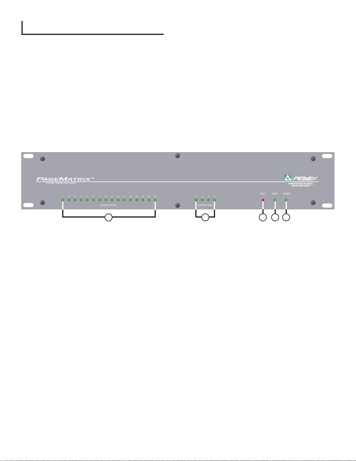
Front Panel
1. Station Status LEDs: (16) Displays green after software activation.
2. Control LEDs: (4) Lights up green when the control data ports are in use.
3. Fault LED: Download error indication when downloading the PageMatrix configuration to the
PageMatrix controller. When this message occurs, download the configuration again.
4. Data LED: Indicates a data transfer to the unit or that valid data exists in memory at power
up.
5. Power : Indicates that the unit is on.
6
1
2 3 4 5
Page 7
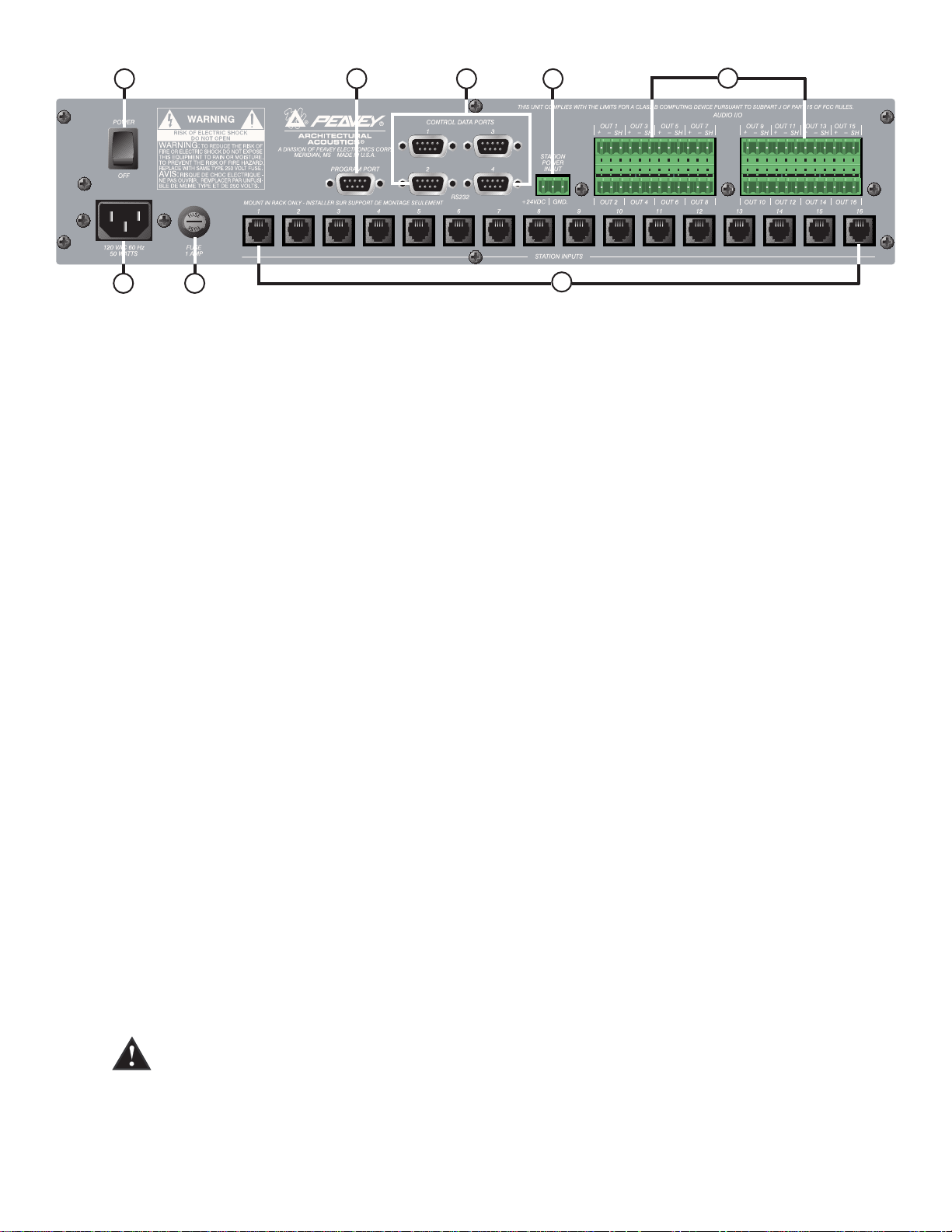
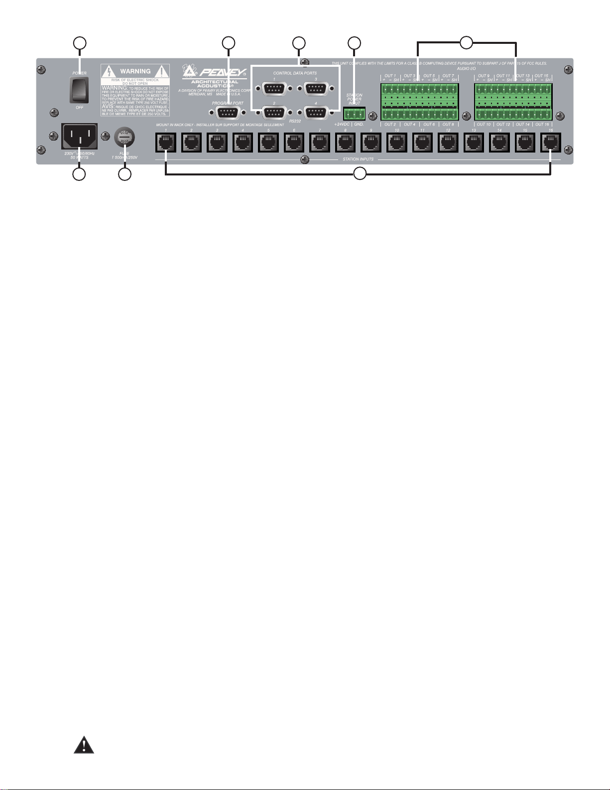
Rear Panel
6. Program Port (RS-232): Accepts PageMatrix software data from the host computerÕs
serial port (Com 1 or Com 2).
7. Control Data Ports (4 RS-232 jacks): Allows connection and control of up to four
MediaMatrix systems.
8. Station Inputs (16 RJ45 jacks): All stations are connected to one of the sixteen
station inputs using standard CAT 5 cable. The cable carries audio from the station and
control data to and from the station, as well as power for the station. Note: This is not a
network connection.
9. Audio Outputs: Four removable ÒPhoenixÓ style connectors are provided for connection of
audio to MediaMatrix Break out Box. Note: Two BoBs (8 channels each) are required for 16
stations.
10. Station Power Input: +24V DC input for emergency station power.
Note: In the event of a power loss to the paging controller, the station power input will power
only the stations to allow audio to pass in an emergency situation. In this case, the stations
will be unable to communicate with the controller, and the controller will be unable to send
control information to the MediaMatrix unit. In the event of a power loss, the MediaMatrix view
file must be configured to route the audio without control input from the PageMatrix controller.
In order for both the controller and stations to remain active, the controller must be connected
to some form of power backup system, such as a UPS.
11. Power Switch: Use to turn the unit on or off.
12. Detachable Power Cord Connector
13. Fuse: 1A at 100V/120V AC~, T1A/250V
500 mA at 230V AC~, T500mA/250V
7
8
1312
11
6
7
10
9
Page 8
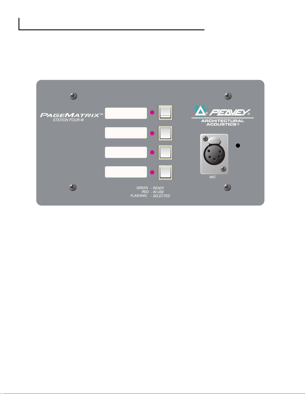
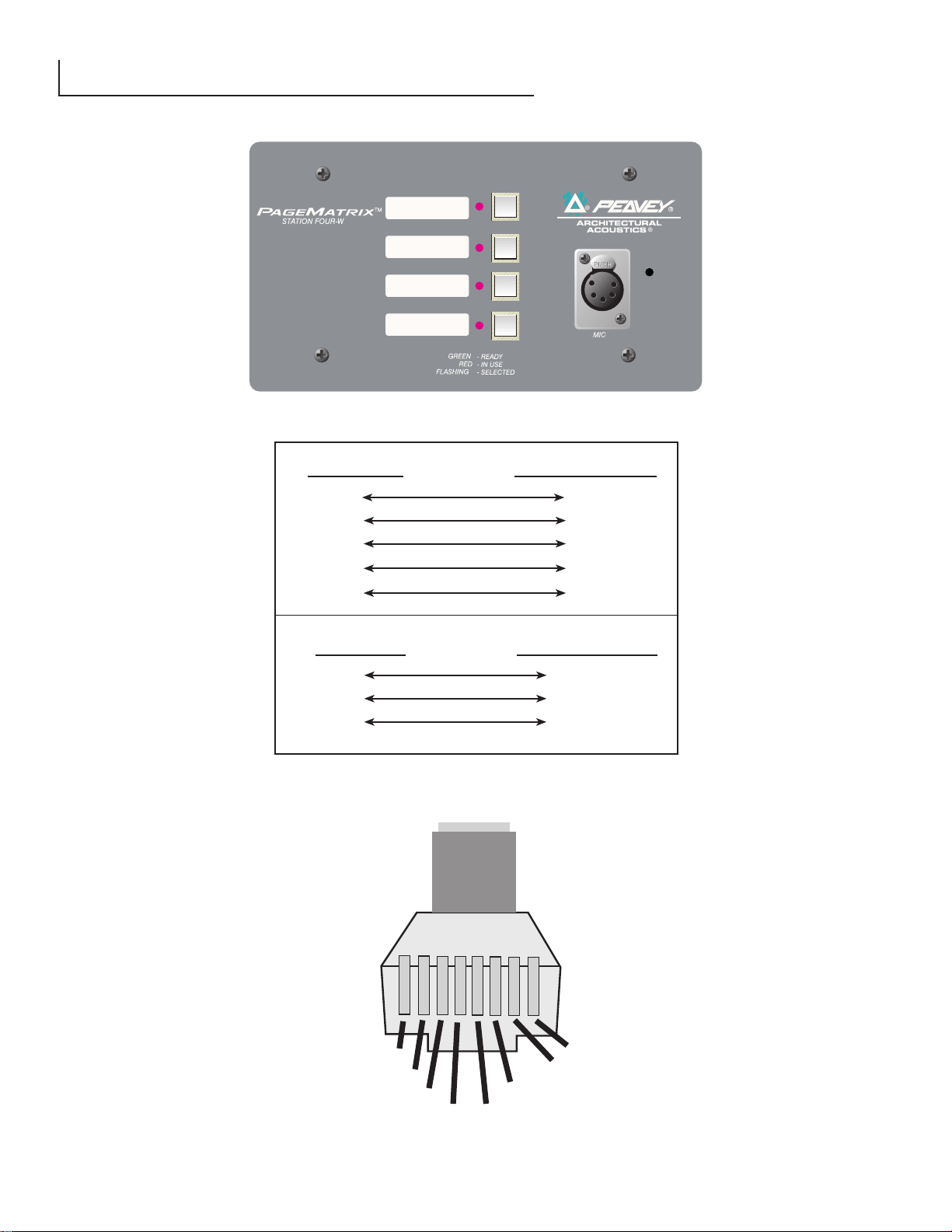
2.2. Station Four-W™Wall-Mount Paging Station
Station Fourª-W is a four button wall mount station that includes a hand-held (5-pin) microphone
with a push-to-talk switch. Each of the four zone presets are defined and programmed by the
PageMatrix software.
Front Panel
Zone Preset buttons w/LEDs(4):
Used to select any of the four zone presets. A green LED indicates the zone is available,
while a red LED indicates it is in use by another station. The LED will blink to confirm
the selection.
Five-pin Mic Input:
Used to connect the supplied 5-pin handheld microphone.
Mic Volume:
Recessed to the right of the microphone input, use a small screwdriver to adjust the mic
gain.
Rear Panel
3-Pin Connector:
This is the analog audio signal output to be connected to the PageMatrix controller.
See the wiring diagram, Appendix 5.3.
4-Pin Connector:
This connects the control data to and from the PageMatrix controller and also the power for
the station. See the wiring diagram, Appendix 5.3.
8
Page 9

9
Station Four-W Operation
▲ LED color indicates status of each of the four Zone presets.
▲ Green indicates the zone is available and not in use by another station.
▲ Red indicates the zone is in use.
▲ When the microphone ÒTalkÓ button is pressed, the selected zone preset LED turns orange to
confirm that it is active. Other stations connected to the system will indicate RED to confirm
that this particular zone is in use.
▲ Press any Zone Preset button to select. The LED will blink confirming the selection.
▲ At power-up, the unit defaults to zone one and after one minute of inactivity reverts back to
zone one.
▲ Hand-held 5-pin mic input is activated by pressing the ÒtalkÓ button.
▲ Zone presets can be labeled in the appropriate white boxes.
▲ If all LEDs flash red at power up, this indicates the station has not been programmed.
▲ If all LEDs flash green at power up, this indicates the station has been
programmed.
About Zone Presets
MediaMatrix defines the zones which can represent single outputs or groups of outputs. PageMatrix
software is used to program the button assignments on the paging stations which enables them to
access one or more zones per button. We refer to the button assignments as zone presets, since
these settings are set initially. They are then downloaded to the PageMatrix controller where they
become active.
About Priority
With PageMatrix, there are no inherent priority settings. Any microphone may be used at any time
and the ÒbusyÓ LED indication identifies when a zone preset is in use by another station. However,
extensive priority levels can be configured and designed within MediaMatrix.
Page 10
10
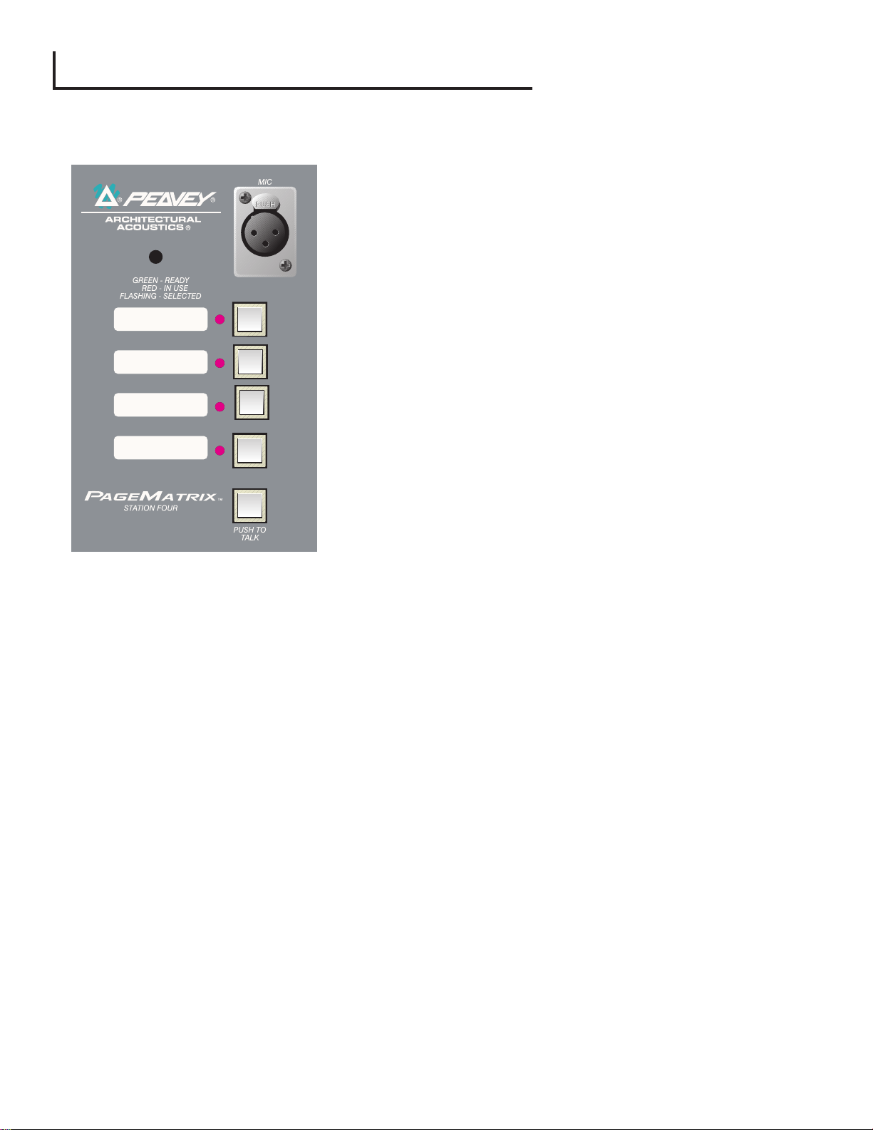
2.3. Station Four™Desktop Paging Station
Station Fourªis a four button desktop station that includes an electret condenser microphone. Each
of the four button zone presets are defined and programmed by the PageMatrix software.
Front Panel
Push To Talk button:
Press and hold to enable the microphone for the
selected zone preset. The selected LED will turn
orange to denote active status while the other zone
preset LEDs become red.
Zone Preset buttons w/ LED(4):
Used to select any one of the four zone presets. A
green LED indicates the zone is available, while a red
LED indicates it is in use by another station. The LED
will blink to confirm selection.
XLR Mic Input:
Phantom powered microphone input
Mic Volume:
Recessed mic gain adjustment
Rear Panel
5-pin Aux Mic Input
For connection of a remote microphone with a push-to-talk feature. See the wiring
diagram, Appendix 5.4. The aux mic is automatically routed to zone preset one.
Station Four Operation
▲ LED color indicates status of each of the four Zone presets.
▲ Green indicates the zone is available and not in use by another station.
▲ Red indicates the zone is in use.
▲ When the Push To Talk button is pressed, the selected zone preset LED turns orange to
confirm that it is active. Other stations connected to the system will indicate RED to confirm
that this particular zone preset is in use.
▲ Press any zone preset button to select. The LED will blink confirming the selection.
▲ At power-up, the unit defaults to zone one and after one minute of inactivity reverts back to
zone one.
▲ Zone presets can be labeled in the appropriate white boxes.
▲ If all LEDs flash red at power up, this indicates the station has not been programmed.
▲ If all LEDs flash green at power up, this indicates the station has been programmed.
▲ The Aux mic input (rear panel) is always routed to zone preset one.
Page 11
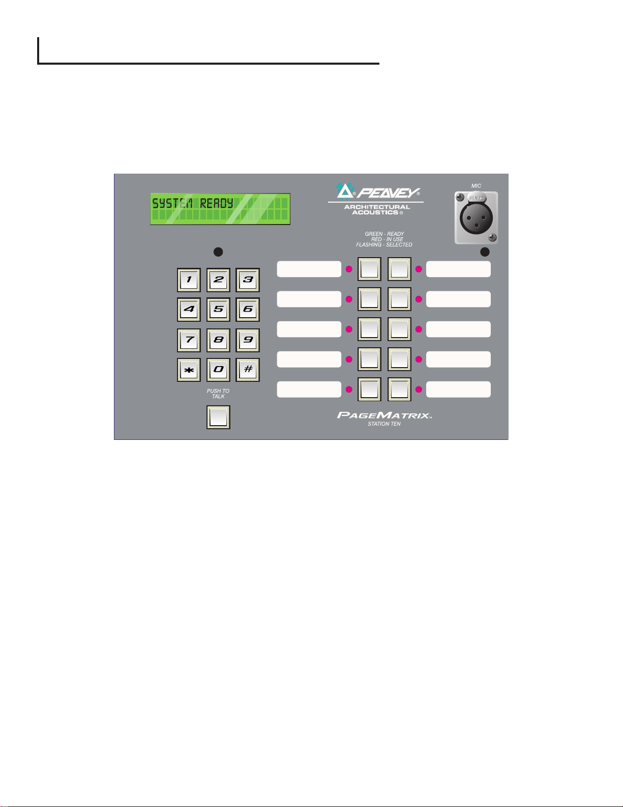
2.4. Station Ten™Desktop Paging Station
Station Tenªis a ten button desktop station that includes an electret condenser microphone. Each of
the ten zone presets are defined and programmed by the PageMatrix software. In addition, a 12
button Òtelephone styleÓ key pad and 20 x 2 LCD panel are provided for selection and indication of
up to 99 ÒvirtualÓ zones. The ten buttons are unique for each station; however, the additional 89
ÒvirtualÓ dial-up zones are the same (global) for each Station Ten unit connected to the PageMatrix
controller. Each of these zone presets are defined and programmed by the PageMatrix software.
Front Panel
Push To Talk button:
Press to activate the microphone for the selected zone preset.
Zone Preset buttons w/ LED(10):
Used to select any of the ten zone presets. A green LED indicates the zone is
available, while a red LED indicates it is in use. The LED will blink to confirm selection.
XLR Mic Input:
Phantom powered microphone input.
Mic Volume:
Recessed mic gain control.
Rear Panel
Aux Mic Input (5-pin):
For connection of a remote microphone with a ÒPush-To-TalkÓ feature. See wiring
diagram, Appendix 5.4. The aux mic is automatically routed to zone preset one.
RJ45 Connector:
For connection to the PageMatrix controller.
11
Page 12

12
Station Ten Operation
▲ LED color indicates status of each of the ten zone presets.
▲ Green indicates the zone is available and not in use by another station.
▲ Red indicates the zone is in use.
▲ When the Push To Talk button is pressed, the selected zone preset LED turns orange to
confirm that it is active. Other stations connected to the system will indicate RED to confirm
that the zone preset is in use.
▲ Press any Zone Preset button to select. The LED will blink confirming the selection.
▲ At power-up, the unit defaults to zone one.
▲ Aux Mic input (5-pin) on the back panel is programmed for zone preset one.
▲ For direct zone preset access, the key pad can be used. Simply enter a one or two digit
number, then press # to select.
▲ The selected zone name (user nameable up to 16 characters within the PageMatrix software)
will be displayed on the 20 x 2 LCD in addition to status (ready/busy/paging)
▲ The upper line of the display provides the station name and status. The second line provides
the zone name.
▲ Zone presets can be labeled in the appropriate white boxes.
▲ If all LEDs flash red at power up, this indicates the station has not been programmed.
▲ If all LEDs flash green at power up, this indicates the station has been programmed.
▲ At power-up, the unit defaults to zone one and after one minute of inactivity reverts back to
zone one.
About Zone Presets
MediaMatrix defines the zones which can represent single outputs or groups of outputs. PageMatrix
software is used to program the button assignments on the paging stations which enables them to
access one or more zones per button. We refer to the button assignments as zone presets, because
these settings are set initially then downloaded to the PageMatrix controller where they become
active.
About Priority
With PageMatrix, there are no inherent priority settings. Any microphone may be used at any time
and the ÒbusyÓ LED indication identifies when a zone preset is in use by another station. However,
extensive priority levels can be configured and designed within MediaMatrix.
Page 13
13
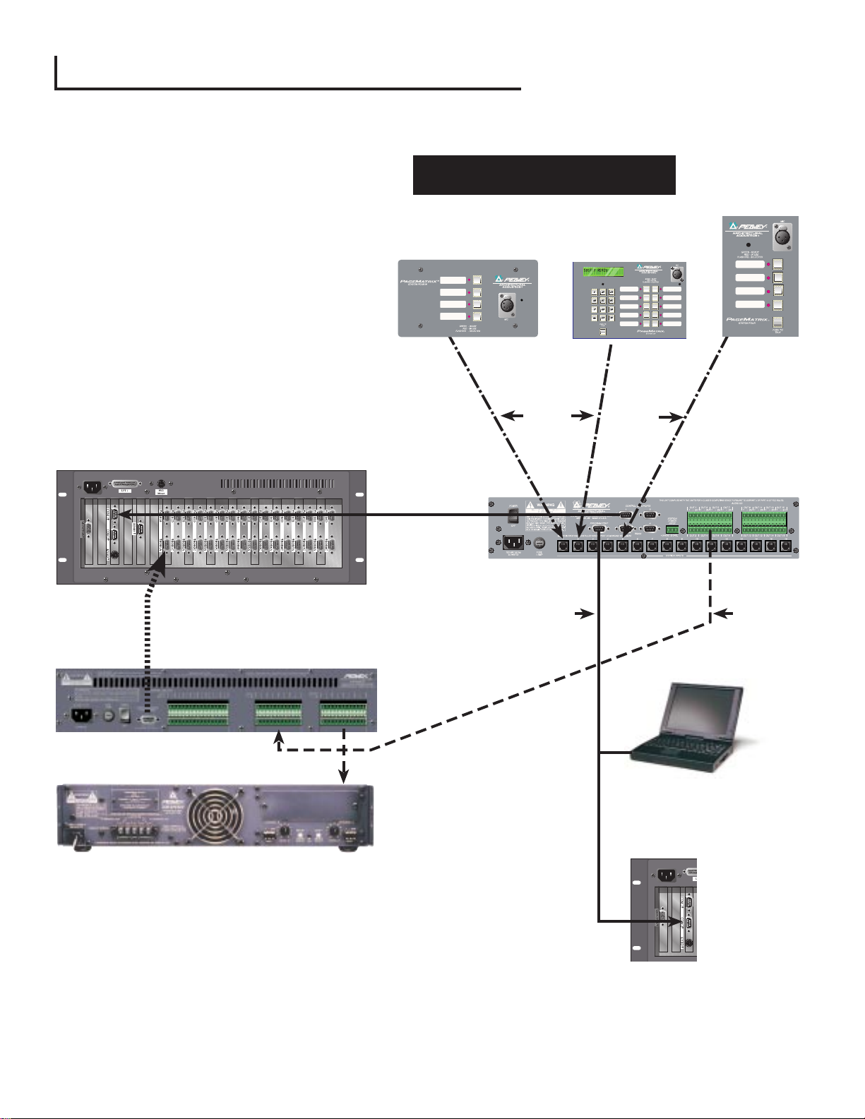
2.4. Typical PageMatrix Connection
Up to 16 Stations of any combination
CAT 5 STANDARD ÒData TypeÓ cable is used.
However, there is voltage on the line. DO NOT
CONNECT to computer networks.
BoB Cable
MediaMatrix
¨
RS-232 Cable
Station 4W
RS-232
Cable
ª
CAT 5*
Cable
Station 10
CAT 5*
Cable
ª
Station 4
PageMatrix
Audio
Cable
ª
ª
IAª 200
Lap Top
OR
MediaMatrix
Com Port
¨
Page 14
3.1. Computer Requirements
Minimum: 486DX-100 or faster PC with
Windows 3.1 / 95 / NT4 or later, 8-16Mb RAM
and one available Com Port.
3.2. Software Installation
Note: With MediaMatrix Mainframe systems
shipped since 1999, the PageMatrix
application is already installed. The instructions below only apply to systems prior to this
time.
The complete PageMatrix software system includes:
1. PageMatrix application (Floppy Disk 1)
2. MediaMatrix view files and PASHAªfiles (Floppy Disk 2)
3. MediaMatrix devices (Floppy Disk 2)
Step One: Installing the PageMatrix software (files in parentheses indicate defaults)
A. Insert Disk One (PageMatrix Installation) into the floppy drive.
B. Run ÒA:\setup.exeÓ.
C. Will prompt for an installation directory (c:\pagemtrx) and a program group name
(PageMatrix). Installs files in that directory and creates program group. When installation
window says ÒInstallation Complete!Ó in red, click the Finish button or cancel button (if there
is no finish button). You do not need to restart your computer after installation.
Step Two: Installing the MediaMatrix view files:
Note: When installing the PageMatrix view files and devices, you will need to know what
directory your MediaMatrix software is in (if it is in a different directory than the factory
defaults).
A. Insert Disk Two (MediaMatrix view Files) into the floppy drive.
B. Run ÒA:\views.exeÓ.
C. This is a self-extracting zip file that will ask you for a directory to place the unzip files.
These files can go anywhere on your hard drive, but it is recommended that you install
them in the View directory in your MediaMatrix root directory(c:\peavey\views).
D. Once the directory is confirmed, click Unzip.
E. Click Close when finished.
Step Three: Installing the MediaMatrix devices
A. Insert Disk Two (MediaMatrix view Files) into the floppy drive.
B. Run ÒA:\devices.exeÓ.
C. This is a self-extracting zip file that will ask you for a directory to place the unzip files.
These files MUST go in the Devices directory in your MediaMatrix root directory
(c:\peavey\devices\standard\paging) If your root directory is different from the default, enter
the proper root directory followed by Òdevices\standard\pagingÓ.
D. Once the directory is confirmed, click Unzip.
E. Click Close when finished.
14
3. PageMatrix Software Description
Page 15

3.2.1. Launching PageMatrix
Windows 95:
1. Under the Start menu, select Programs.
2. Find the PageMatrix directory and select it.
3. Locate PageMatrix , and select it.
W
indows 3.1:
1. Find the PageMatrix Program Group within the Program Manager
2. Doulbe click the group, then double click the PageMatrix Icon.
Note: For systems that are not pre-loaded with PageMatrix, the MediaMatrix Program Launcher can
be used. This is found under the MediaMatrix Device/Miscellaneous menu. See appendix 5.2.
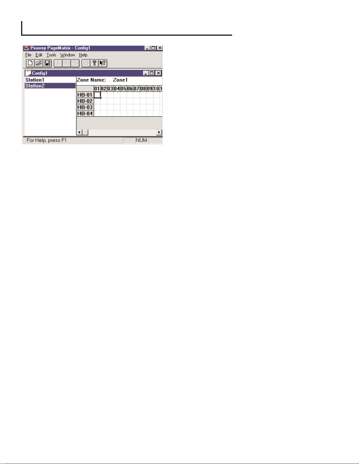
3.2.2. Stations and Zones
The PageMatrix application simplifies the process of
programming the remote stations. A grid matrix is
presented that lists each button for the selected
station. HB stands for hardware button and the
following number signifies the specific button on the
station. Station buttons are displayed in rows and
potential zone assignments in columns.
To assign the button, simply left-click the desired zone
to select it (a bold outline appears around the
selection), then right-click to confirm (turns red).
Zones represent physical locations and outputs
connected via MediaMatrix BoB outputs, amplifiers, and speakers. Note: If you only use one BoB, a
maximum of 8 zones will be available.
Programming the Paging Stations with the PageMatrix application
[note: see the next chapter (Menu Bar) for additional information]
Use the ÒInsert StationÓ or ÒAdd StationÓ (Edit Menu) as necessary to include your hardware
stations in the programming. After setting up the PageMatrix application, the layout on the left
displays a column listing all the connected paging stations. To the right is a matrix list of zones at
the top and columns of buttons by number. Select the station you wish to program first, then use
the mouse to activate zones for each button. When finished, download the configuration to the
Pagematrix controller (File menu). Now your page station buttons are programmed and ready for
use.
Naming Zone Presets When Using the Station Ten
With the Station Ten, a 20 x 2 display is provided for viewing the zone presets. The zone presets are
named within the PageMatrix application. When a 10 button station is inserted (Edit/Insert Station),
the LCD Text option appears at the top of the screen. Simply select a virtual button, then highlight
the default title and rename as you wish up to 16 characters.
15
Page 16
3.3. PAGEMATRIX APPLICATION MENU BAR OVERVIEW
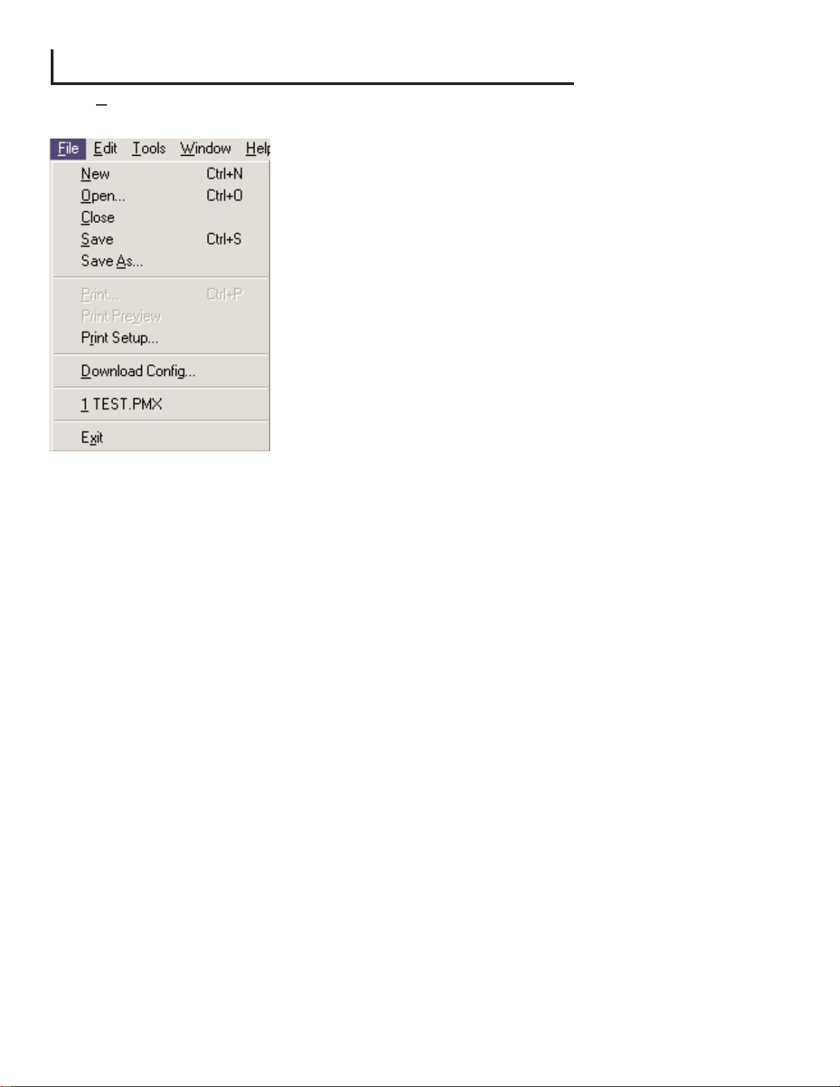
3.3.1 File Menu
New
Selecting New opens a new configuration set to factory
defaults.
Open
Brings up the standard file open dialog that allows you to
open an existing file (*.pmx).
Close
Closes the active configuration.
Save
Save the current configuration and any edits you have
made.
Save As
Brings up the standard file save dialog and allows you to
rename the file before you save it.
Print
Not active at this time.
Print Preview
Not active at this time.
Print SetupÉ
Not active at this time.
Download ConfigurationÉ
This option allows you to send your configuration settings to the PageMatrix controller. Since
this will replace the current configuration loaded into the controller, a ÒDo you wish to
continue?Ó dialog gives you the opportunity to cancel.
Recent File List
This area of the menu lists the most recent configurations. These configurations may be
opened directly from the list.
Exit
Closes PageMatrix.
16
Page 17
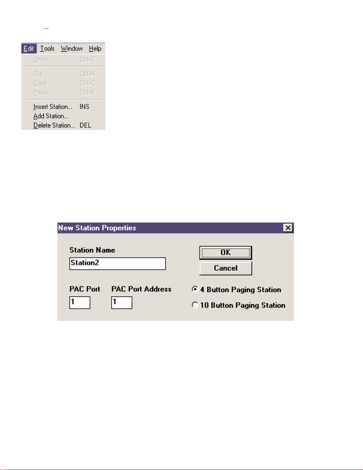
3.3.2. Edit Menu
Undo
Not active at this time
Cut
Not active at this time
Copy
Not active at this time
Paste
Not active at this time
Insert Station
Creates a new paging station that is available for editing. It is placed in the list before the currently
selected station. Selecting this option opens the ÒNew Station PropertiesÓ dialog and allows the
following edits:
Station Name: Up to 16 characters.
Number of buttons: 4 or 10.
PAC Port: Identifies the specific port (1-16) where the station is connected to the PageMatrix
Controller.
PAC Port Address: Currently, always set to one.
Add Station
Creates a new paging station that is available for editing. It is placed at the end of the list. Selecting
this option opens the ÒNew Station PropertiesÓ dialog and allows the following edits:
Station Name: Up to 16 characters.
Number of buttons: 4 or 10.
PAC Port: Identifies the specific port (1-16) where the station is connected to the PageMatrix
controller.
PAC Port Address: Currently, always set to one.
Delete Station
Removes the currently selected station. The ÒAre You SureÓ dialog opens for confirmation.
17
Page 18
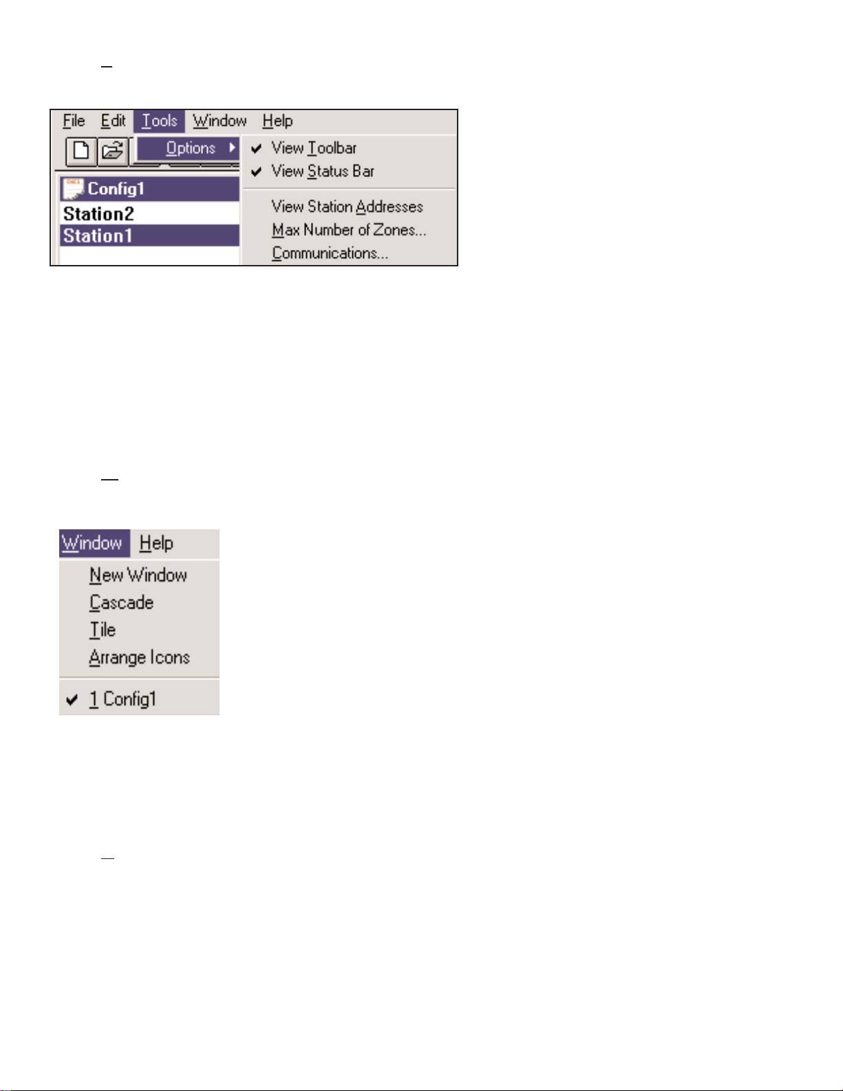
3.3.3. Tools Menu/Options
View Toolbar
Show or hide the screen toolbar.
View Status Bar
Show or hide the status bar at
the bottom of the window.
View Station Addresses
Displays the station address in
front of the station name.
Max Number of Zones
Use this parameter to set the maximum number of zones used in your system.
Communications
Used to set the upload/download port. In addition to COM 1-4, an Offline Programming
option is available when working remotely.
3.3.4. Window Menu
New Window
Creates a new window.
Cascade
Standard Windows function that arranges all open configuration
windows in a cascade pattern.
Tile
Standard Windows function that arranges all open configuration
windows in a tile pattern.
Arrange Icons
Aligns minimized child windows.
Configuration Display
Lists all open configurations.
3.3.5. Help Menu
About PageMatrix
Displays the PageMatrix start-up screen.
18
Page 19

4.0. Typical PageMatrix Operation
4.1. Overview
4.1.1. The components
PageMatrix / MediaMatrix paging systems consist of five primary components:
▲ At least one PageMatrix paging station connected to the PageMatrix controller via the
proper category five cabling
▲ PageMatrix controller with the appropriate configuration file loaded
▲ PageMatrix application software
▲ A MediaMatrix audio system with PASHA running
▲ A proper PASHA.ini file configured for the ÒView FileÓ compiled
4.1.2. Connections
Paging stations connect to the PageMatrix controller via CAT 5 cabling. This cable
carries three ÒsignalsÓÐ the analog audio from the microphone, the voltage required to power
the remote paging station, and the serial control data which will determine where the
microphoneÕs audio signal will be routed by MediaMatrix.
The analog microphone signals from all paging stations are individually connected from their
outputs on the rear of the PageMatrix Controller to the signal inputs of MediaMatrix break out
boxes (ÒBoBsÓ).
One of the serial outputs on the rear of the PageMatrix Controller connects to one of the
Com Ports on the rear of the MediaMatrix frame.
4.1.3. The Desktop Paging Stations (Station Four and Station Ten)
There is no local switching of the ÒPush-to-TalkÓ microphone connected to the paging station.
In all models the microphone is active or ÒonÓ at all times. Pressing station buttons results in
activity of the serial communication to the PageMatrix Controller only.
4.1.4. The PageMatrix Controller
There are three functions of this device:
1: To provide power to the Paging stations.
2: To pass the analog microphone signals from the paging stations to the inputs of the
MediaMatrix systemÕs BoBs.
19
Page 20

3: To interpret the proprietary control data from the paging stations and convert it to
standard serial strings which can be forwarded to MediaMatrix.
Microphone signals from the paging stations are not acted upon by the PageMatrix Controller,
but are simply passed through the box as received. Any switching or routing is done within
MediaMatrix.
4.1.4. The MediaMatrix system and PASHA
Among many other tasks, the MediaMatrix system receives the analog audio from the Paging
Stations via the PageMatrix controller, converts it to digital and performs all processing of
those signals, including the routing of these signals to the various ÒzonesÓ. These routing
functions are accomplished by special PageMatrix devices within the systemÕs ÒView FileÓ
which are controlled from the PageMatrix Controller via PASHA.
4.1.5. Push-to-talk switchÐWhat happens?
1: Pressing a stationÕs zone preset button selects the configured zones in MediaMatrix.
2: When the push-to-talk switch is pressed, the PageMatrix Controller immediately sends the
proper serial command to the MediaMatrix Com port. (The serial command sent is pre
determined by the PageMatrix configuration file which has been downloaded and is
running in the controller.)
3: This serial command is interpreted by MediaMatrix (via PASHA) and ÒpressesÓ the
appropriate router buttons in the MediaMatrix view file to send the audio to the zone or
combination of zones selected by the paging station.
4: Audio passes to the zone(s) through MediaMatrix as long as the push-to-talk button on the
station remains pressed.
5: Functions such as paging priorities, signal source ducking, zone equalization, etc. are all
functions of the MediaMatrix system and are not directly acted upon by the PageMatrix
components.
4.1.6. Operation within MediaMatrix
Paging devices can be complicated systems consisting of multiple Òmixing routers.Ó For
example, programming a paging device which consists of 8 stations and 32 buttons requires
that a PASHA file be written addressing each of the matrix locations (256 parameters). Since
programming your own Pasha files would require extensive time, we have provided a variety
of view files and associated PASHA.INI files to simplify the task. We highly recommend you
use the files weÕve provided on floppy disk and edit them for your specific application.
20
Page 21

Basic OperationÐHere we go...
1. Find the appropriate .txt file for the device you wish to use.
2. Rename this file to pasha.ini and place in the Peavey directory (mediamatrix\views).
Note: If you wish to keep the original pasha.ini file, just rename it.
3. Open MediaMatrix (if not already launched).
4. From the Device menu select ÒPagingÓ to view the available devices.
5. Select an existing device and wire it accordingly.
6. Test the routings and zones.
Example:
Suppose we want to use the 1632.pav file. Rename the 1632.txt file to pasha.ini.
Move this newly created pasha.ini to the MediaMatrix root directory.
4.2. Troubleshooting 101
▲ Remember, the view file must be compiled.
▲ Make sure Pasha.com(pasha.com1, pasha.com2, pasha.com3, or pasha.com4) is launched
and matches the same com port used for PageMatrix.
▲ Be sure to launch PageMatrix and program a test file.
▲ In MediaMatrix, check the view file visual monitors to determine if the system is responding.
▲ Finally, check cable type, connection, and port settings.
21
Page 22

22
5. APPENDIX
5.1. Factory Support
Peavey provides customer support and service direct from the factory. If you need further assistance
or information, donÕt hesitate to call us. You can reach us 8 a.m. - 5 p.m. CST at (800) 543-2991 or
(601) 483-5376. The address for correspondence/literature on current or new products is:
Peavey Electronics Corp. ¥ MediaMatrix Support Group ¥ 711 A St. ¥ Meridian, MS 39301
You can also access helpful tips, specifications, FAQs, sample files, application notes and other
Peavey Architectural Acoustics equipment product information 24 hours a day, seven days a week at
our site on the World Wide Web. The URL is:
http://www.peavey.com/division/arch/index.html
In order to provide you with the best technical support, it will probably be necessary to see your view
file so we can accurately diagnose your problem. This also helps to streamline your work and make
your system more efficient. Using the Internet and e-mail, we can quickly get you up and running.
Please direct your mail and attached view file to:
George Douglas, National Sales Manager george@peavey.com
Ken Valentine, Central District Manager ken@peavey.com
Will Roland, Western District Manager will@peavey.com
Joel Moak, Southeastern District Manager joel@peavey.com
Levin Culpepper, Internal Tech Support Coordinator levin@peavey.com
Brent Harshbarger, Product Manager brent@peavey.com
If you need emergency assistance after business hours or on the weekend, you may reach one of
us on our SkyPager at (800) 759-7243. When you hear the prompt tone, enter the PIN 113-4326.
Please reserve this for true MediaMatrix emergencies or weekend use.
A R C H I T E C T U R A L A C O U S T I C S
¨
711 A Street ¥ Meridian, MS 39301
(601) 483-5376 ¥ FAX (601) 486-1678
http://www.peavey.com ¥ ©1998
Features and specifications are subject to change without notice.
Page 23
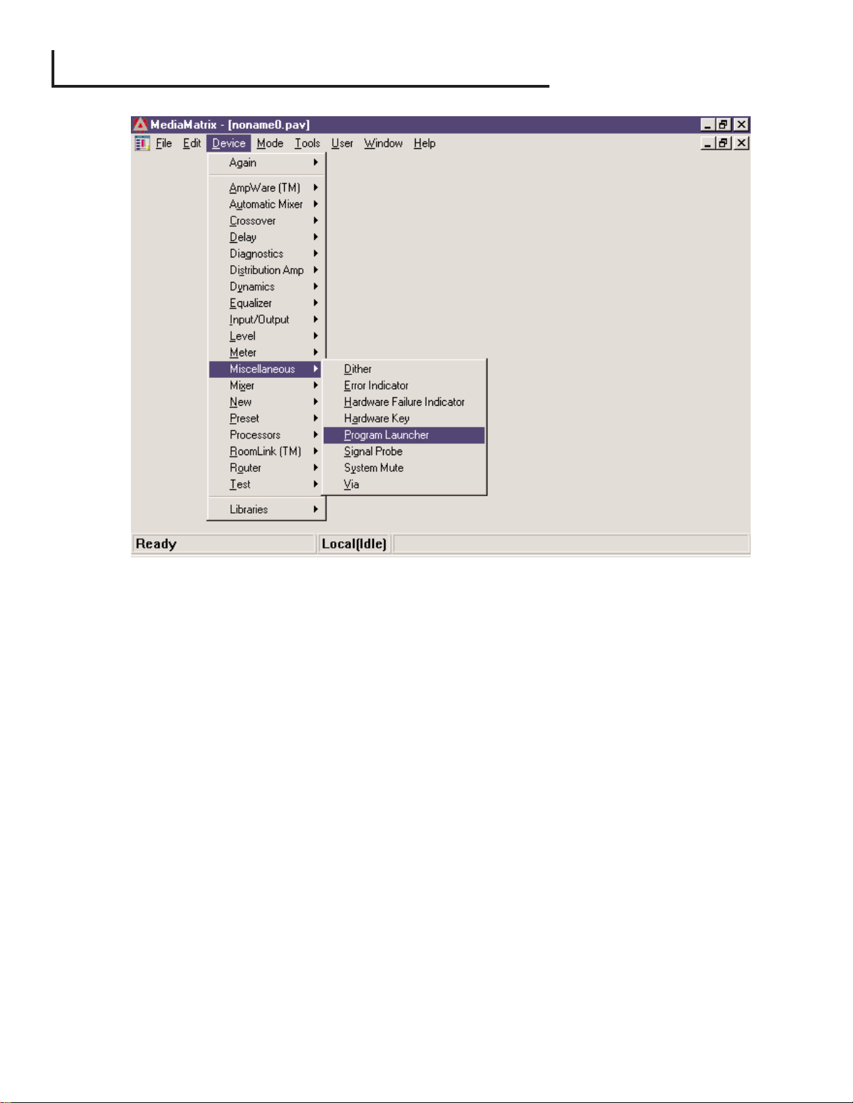
The Program Launcher is found in the Device/Miscellaneous Menu. It is used to make it easy to
open another Windows application while you are using MediaMatrix. You can label the Program
Launcher block and include it in any window of a MediaMatrix design. The Program Launcher device
can either launch another Windowsªapplication or switch to that application if it is already running.
The Object Properties dialog for this object has a field titled ÒRun this programÓ that contains the
complete path and file name and optional command line arguments of the program you want to run.
You can browse the applications that are currently running by pressing the ÒWindow Title...Ó button,
and you can browse for executables (*.exe) by pressing the ÒFile Name...Ó button. The object can
perform its action, either running or switching to the other application, on either a single mouse click
or on a double-click as determined by the settings of the ÒRun program onÓ radio buttons. In Edit
Mode, the action is always on a double-click.
23
5.2. Using the MediaMatrix Program Launcher
Page 24
24
5.3. Station 4-W Wiring Diagram
Cat 5 Plug 4-Pin Connector
1 485+
2 485 3 GND
4 24V+
5 GND
Cat 5 Plug 3-Pin Connector
6 GND
7 Line Out+
8 Line Out -
CAT 5
8 7 6 5 4 3 2 1
8
7
6
5
3
4
1
2
This is not a network connection.
NOTE:
Page 25
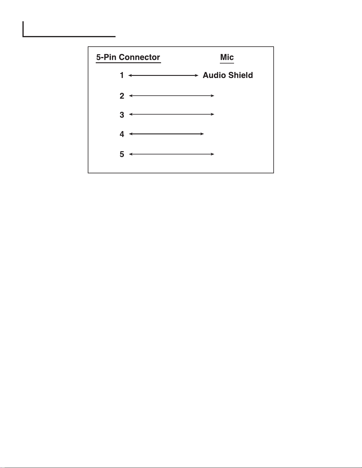
5.4. 5-Pin Wiring Diagram
25
Audio +
Audio -
Mic Switch
GND
Page 26

26
5.5. Configuring the PageMatrix Controller
As mentioned previously, the PageMatrix controller supports up to sixteen paging stations
simultaneously. In larger applications where multiple controllers are necessary, the various
PageMatrix units must be configured for IDs beyond the default 1-16 setting. This is accomplished
by changing the DIP switch settings inside the unit.
1. Remove top plate of the controller (six screws).
2. Now viewing the inside of the unit, find the DIP switch (labeled SW100) located at the front left
side of the unit.
3. You will only adjust switches 1 and 2 according to the chart below.
4. Switches 3 through 8 are inactive.
NOTE: Factory settings default to 1-16
DIP SETTINGS
12345678
O
N
12345678
O
N
12345678
O
N
CONTROLLER IDs
Stations 1 - 16
Stations 17 - 32
Stations 33 - 48
12345678
O
N
Stations 49 - 64
Page 27

27
Power Requirements:
Domestic: 120V AC~, 60 Hz, 50W
Export: 100V AC~, 50/60 Hz, 50W
230V AC~, 50/60 Hz, 50W
Included Accessories:
IEC Line Cord
(4) 12 position Phoenix-type connectors
(1) 3 position Phoenix-type connector
Dimensions and Weight:
3.5" H x 19" W x 11.69" D
(excluding connectors)
13.7 lbs.
Category 5 cable length
Maximum 1,000 ft
Note: Standard Òdata typeÓ cable is used;
however, there is voltage on the line.
DO NOT connect to computer networks.
Station Four-W Mounting
Station 4-W Wallmount does not come with a back panel.
It is recommended to use a standard 4 Gang Electrical box with
these dimensions: 3.75" H x 7.5" W x 2.0" (Min) D.
Maximum Input Level:
Station 4 Wallmount: -22 dBu
Station 4 Desktop: -22 dBu
Station 10 Desktop: -22 dBu
Maximum Output Level:
Station 4 Wallmount: +25 dBu
Station 4 Desktop: +25 dBu
Station 10 Desktop: +25 dBu
Input Impedance:
Station 4 Wallmount: 2.2K ohms
Station 4 Desktop: 2.2K ohms
Station 10 Desktop: 2.2K ohm
Output Impedance:
Station 4W Wallmount: 200 ohms
Station 4 Desktop: 200 ohms
Station 10 Desktop: 200 ohms
Frequency Response:
Station 4 Wallmount: 20Hz to 20 kHz (+0, -2 dB)
Station 4 Desktop: 20Hz to 20 kHz (+0, -2 dB)
Station 10 Desktop: 20Hz to 20 kHz (+0, -2 dB)
Total Harmonic Distortion:
Station 4 Wallmount:Less than 0.01% at 1 kHz
Station 4 Desktop: Less than 0.01% at 1 kHz
Station 10 Desktop: Less than 0.01% at 1 kHz
Signal-to-Noise Ratio:
Station 4 Wallmount: Greater than 88 dB
Station 4 Desktop: Greater than 85 dB
Station 10 Desktop: Greater than 84 dB
Phantom Power:
Station 4 Wallmount: +48V DC
Station 4 Desktop: +48V DC
Station 10 Desktop: +48V DC
Power Requirements:
Station 4 Wallmount: 48mA at +24V DC
Station 4 Desktop: 55mA at +24V DC
Station 10 Desktop: 92mA at +24V DC
Dimensions:
Station 4 Wallmount: 4.5" H x 8.2" W x 1" D
Station 4 Desktop: 4.0" H x 5.2" W x 7.1" D
Station 10 Desktop: 4.0" H x 10.4" W x 7.1" D
5.6. Specifications
PageMatrix Controller
Paging Stations
Page 28

1. Introducción
Lo felicitamos por su sabia elecci—n del sistema PageMatrixªpara sus proyectos de
intercomunicaci—n actuales y futuros. Utilizado en conjunto con nuestro aclamado sistema
de audio digital MediaMatrix¨, el sistema PageMatrix provee un enfoque integrado y flexible
para todas las aplicaciones de intercomunicaci—n profesionales.
MediaMatrix sirve como unidad central de procesamiento al proyecto en su totalidad,
control‡ndolo, desde el encaminamiento de la se–al, hasta la administraci—n integral
del sistema de intercomunicaci—n. El sistema PageMatrix provee varias estaciones de
intercomunicaci—n, que se configuran f‡cilmente para satisfacer cualquier requisito de
localizaci—n/zona. Adem‡s, estas estaciones de intercomunicaci—n son port‡tiles, lo que
significa que el enchufe/puerto de pared contiene la identidad de la estaci—n de
intercomunicaci—n conectada a Žl.
Los componentes de hardware del sistema PageMatrix, incluyen el controlador PageMatrix, que
ocupa dos espacios de bastidor, y tres tipos de estaciones de intercomunicaci—n. El controlador
PageMatrix soporta cualquier combinaci—n de hasta 16 estaciones de intercomunicaci—n, para la
gesti—n de audio se conecta con las cajas distribuidoras (BoB) del sistema MediaMatrix y para el
control de datos se conecta con el puerto serie RS-232 de la estructura de ese sistema. Hay
disponibles tres tipos de estaciones de intercomunicaci—n: la Station Four-WªWall Mount (de pared,
de cuatro botones), Station FourªDesktop (de mesa, de cuatro botones) y la Station TenªDesktop
(de mesa, de diez botones).
Los componentes de software incluyen:
▲ El software PageMatrix
▲ Los archivos de visualizaci—n MediaMatrix
▲ Los archivos de intercomunicaci—n MediaMatrix PASHA
ª
(que se corresponden con los
archivos de visualizaci—n apropiados)
La aplicaci—n PageMatrix provee un medio gr‡fico para programar los botones preconfigurados de
zona de cada estaci—n agregada. Una vez que finaliza la configuraci—n, la transmite directamente al
controlador PageMatrix para su operaci—n. No es necesario acceder nuevamente a la aplicaci—n
PageMatrix, hasta que llegue el momento de actualizar la configuraci—n.
Caracter’sticas
▲ Disponibles 99 zonas de intercomunicaci—n
▲ Con hasta 16 estaciones de intercomunicaci—n simult‡neamente
▲ Se puede utilizar cualquier combinaci—n de estaciones de cuatro o diez botones
▲ Todas las estaciones tienen indicadores LED multicolores, que indican el estado de precon
figuraci—n de la zona.
ESPA„OL
28
Page 29

▲ El controlador dispone de una entrada para el funcionamiento con alimentaci—n a distancia
de +24 VCC.
▲ Se utilizan conectores tipo Phoenix para llevar la se–al de intercomunicaci—n de audio a las
cajas distribuidoras BoB.
▲ El controlador sustenta hasta cuatro sistemas MediaMatrix.
▲ En el panel frontal del controlador hay 16 LED de estaci—n, que indican el estado de cada
una de ellas.
2. Descripción del hardware
2.1 Controlador PageMatrix
El controlador PageMatrix es el coraz—n del sistema. A travŽs del puerto serie RS-232, se conecta
a la estructura del sistema MediaMatrix, en el cual se ejecuta el software de los sistemas
MediaMatrix y PageMatrix. En la pr‡ctica, un controlador PageMatrix puede controlar hasta cuatro
sistemas MediaMatrix separados (se proveen cuatro puertos de datos).Adem‡s de los puertos
de control, hay un puerto exclusivo, disponible para recibir los datos del software PageMatrix.
Normalmente, una vez que se dise–a la configuraci—n PageMatrix, se la transfiere al controlador
PageMatrix y el sistema MediaMatrix se desconecta del puerto de programas.
El controlador PageMatrix sustenta hasta 16 estaciones de intercomunicaci—n exclusivas, lo que
incluye cualquier combinaci—n de estaciones Station Four-Wª, Station Fourªy Station Tenª.
Consulte los diagramas del panel delantero
en la secci—n de inglŽs de est manual pg. 6
Panel Frontal
1. LED indicadores de estado de las estaciones: (16) Muestran el color verde despuŽs de la
activaci—n del software.
2. LED indicadores de control: (4) Se encienden de color verde cuando est‡ en uso el puerto
de control de datos.
3. LED indicador de fallas: Indicaci—n de error al cargar la configuraci—n PageMatrix en el
controlador PageMatrix. Cuando se produce ese mensaje, vuelva a cargar la configuraci—n.
4. LED indicador de datos: Indica la transferencia de datos a la unidad o la existencia de
datos en la memoria al poner en marcha el sistema.
5. LED de encendido: Indica que la unidad est‡ activada.
29
Page 30
Panel posterior
6. Puerto de programas (RS-232): Acepta los datos del software PageMatrix desde el puerto
serie (Com 1 o Com 2) de la computadora central.
7. Puertos de datos (4 enchufes RS-232 hembra): Permiten la conexi—n y el control de hasta
cuatro sistemas MediaMatrix.
8. Entradas de estaciones (16 enchufes RJ45 hembra): Todas las estaciones est‡n
conectadas a una de las 16 entradas de estaci—n, mediante un cable CAT 5 est‡ndar. El
cable transporta se–ales de audio desde la estaci—n y datos de control hacia y desde la
estaci—n, as’ como alimentaci—n para la misma. Nota: ƒsta no es una conexi—n de red
inform‡tica.
9. Salidas de audio: Se proveen cuatro conectores desmontables tipo ÒPhoenixÓ para la
conexi—n del audio a la caja distribuidora BoB del sistema MediaMatrix. Nota: Para 16
estaciones, se requieren dos cajas distribuidoras BoB (de 8 canales cada una).
10. Entrada de alimentaci—n a la estaci—n: Entrada de +24 VCC para alimentaci—n de
emergencia de la estaci—n.
Nota: En el caso de que se interrumpa la alimentaci—n elŽctrica al controlador del sistema de
intercomunicaci—n, la entrada de alimentaci—n a la estaci—n s—lo alimenta a la misma para
permitir el paso de la se–al de audio en una situaci—n de emergencia. En este caso, las
estaciones no pueden comunicarse con el controlador y el controlador puede enviar
informaci—n de control a la unidad MediaMatrix. En caso de pŽrdida de alimentaci—n, el
archivo de visualizaci—n del sistema MediaMatrix debe estar configurado para encaminar la
se–al de audio sin entrada de se–al de control del controlador PageMatrix. A fin de que tanto
el controlador como las estaciones permanezcan activadas, el controlador debe estar
conectado a un sistema de respaldo de la alimentaci—n, tal como una unidad de alimentaci—n
ininterrumpible (UPS).
11. Interruptor de encendido: Utilizado para activar y desactivar la estaci—n.
12. Conector desmontable del cable de alimentaci—n
13. Fusible: 1 A a 100/120 VCA~, T1A/250V
500 mA a 230 VCA~, T500 mA/250V
8
1312
11
6
7
10
9
30
Page 31

2.2. Estación de intercomunicación de pared Station Four-W
™
Es una estaci—n de intercomunicaci—n que incluye un micr—fono port‡til (de 5 terminales) con
un pulsador para hablar. Cada una de las preprogramaciones de las cuatro zonas de
intercomunicaci—n se define y programa con el software PageMatrix.
Panel frontal
Botones de zonas preprogramadas con LED indicadores (4):
Utilizados para seleccionar cualquiera de las cuatro zonas preprogramadas. El LED de color
verde indica que la zona est‡ disponible, mientras que el de color rojo indica que est‡ siendo
utilizada por otra estaci—n. El LED indicador destella para confirmar la selecci—n.
Entrada de micr—fono de 5 terminales:
Se utiliza para conectar el micr—fono port‡til de 5 terminales suministrado.
Volumen de micr—fono:
Embutido a la derecha de la entrada de micr—fono. Utilice un destornillador peque–o para
ajustar la ganancia de micr—fono.
Panel posterior
Conector de 3 terminales:
Es la salida de la se–al anal—gica de audio para conectarse al controlador PageMatrix.
Consulte el diagrama de cableado en el ApŽndice 5.3.
Conector de 4 terminales:
Conecta los datos de control hacia y desde el controlador PageMatrix y tambiŽn la
alimentaci—n de la estaci—n. Consulte el diagrama de cableado en el ApŽndice 5.3.
31
Page 32

Operación de la estación Station Four-W
▲ El color del LED indica el estado de cada una de las zonas preprogramadas.
▲ El color verde indica que la zona est‡ disponible y que no est‡ siendo utilizada por
otra estaci—n.
▲ El color rojo indica que la zona est‡ en uso.
▲ Cuando se oprime el bot—n para hablar, el LED indicador de la zona preprogramada se
ilumina de color naranja, para confirmar que est‡ activada. En las otras estaciones
conectadas al sistema, los LED se iluminan de color rojo, para confirmar que esa zona
preprogramada est‡ en uso.
▲ Para seleccionar una zona preprogramada, oprima su bot—n. El LED indicador destella para
confirmar la selecci—n.
▲ Al encender el sistema, la estaci—n, por defecto, selecciona la zona 1. DespuŽs de un minuto
de inactividad vuelve a la zona 1.
▲ El micr—fono port‡til de 5 terminales se activa oprimiendo el bot—n para hablar.
▲ Las zonas preprogramadas se pueden rotular en las casillas de color blanco
correspondientes.
▲ Si todos los LED indicadores destellan en rojo al encender el sistema, eso indica que la
estaci—n no ha sido programada.
▲ Si todos los LED indicadores destellan en verde al encender el sistema, eso indica que la
estaci—n ha sido programada.
Acerca de las zonas preprogramadas
El sistema MediaMatrix define las zonas, que pueden ser salidas independientes o grupos de
salidas. El software PageMatrix se utiliza para programar las asignaciones de los botones de las
estaciones de intercomunicaci—n, que las habilitan para acceder a una o m‡s zonas por bot—n.
Nos referimos a las asignaciones a los botones como Òzonas preprogramadasÓ, porque esas
programaciones se establecen inicialmente y luego se cargan en el controlador PageMatrix donde
se activan.
Acerca de la prioridad
Con el sistema PageMatrix, no hay par‡metros de prioridad inherentes a cada estaci—n f’sica.
Cualquier micr—fono se puede utilizar en cualquier momento y el LED indicador ÒocupadoÓ identifica
cuando una zona preprogramada es utilizada por otra estaci—n. Sin embargo, en el sistema
MediaMatrix se pueden configurar y asignar niveles de prioridad amplios.
32
Page 33

2.3. Estación de intercomunicación de mesa Station Four
™
Es una estaci—n de cuatro botones, que incluye un micr—fono de condensador de electreto. Cada
una de las preprogramaciones de las cuatro zonas de intercomunicaci—n se define y programa con
el software PageMatrix.
Panel frontal
Pulsador para hablar:
MantŽngalo presionado para habilitar el micr—fono para la
zona preprogramada seleccionada. El LED indicador se
ilumina con luz naranja, para denotar la condici—n de
activado, mientras que los LED indicadores de las otras
zonas se iluminan de color rojo.
Botones de zonas preprogramadas con LED indicadores (4):
Utilizados para seleccionar cualquiera de las cuatro zonas
preprogramadas. El LED de color verde indica que la zona
est‡ disponible, mientras que el LED de color rojo indica
que est‡ siendo utilizada por otra estaci—n. El LED
indicador destella para confirmar la selecci—n.
Entrada XLR de micr—fono:
Entrada de micr—fono con alimentaci—n fantasma.
Volumen de micr—fono:
Ajuste embutido de ganancia del micr—fono
Panel posterior
Entrada de micr—fono de 5 terminales:
Se usa para conectar un micr—fono remoto con pulsador para hablar. Consulte el diagrama
de cableado del ApŽndice 5.4. El micr—fono auxiliar se encamina autom‡ticamente a la
zona preprogramada 1.
Operación de la estación de cuatro botones
▲ El color del LED indica el estado de cada una de las zonas preprogramadas.
▲ El color verde indica que la zona est‡ disponible y que no est‡ siendo utilizada por
otra estaci—n.
▲ El color rojo indica que la zona est‡ en uso.
▲ Cuando se oprime el bot—n para hablar, el LED indicador de la zona preprogramada se
ilumina con luz naranja, para confirmar que est‡ activada. En las otras estaciones
conectadas al sistema, los LED se iluminan de color rojo, para confirmar que esa zona
preprogramada est‡ en uso.
▲ Para seleccionar una zona preprogramada, oprima el bot—n. El LED indicador destella para
confirmar la selecci—n.
▲ Al encender el sistema, la estaci—n, la unidad selecciona por defecto la zona 1. DespuŽs de
un minuto de inactividad vuelve a la zona 1.
33
Page 34

▲ Las zonas preprogramadas se pueden rotular en las casillas color blanco correspondientes.
▲ Si todos los LED indicadores destellan con luz roja al encender el sistema, significa que la
estaci—n no ha sido programada.
▲ Si todos los LED indicadores destellan con luz verde al encender el sistema, significa que la
estaci—n ha sido programada.
▲ La entrada de micr—fono auxiliar (panel posterior), siempre se encamina a la zona
preprogramada 1.
2.4. Estación de intercomunicación de mesa Station Ten
™
Es una estaci—n de diez botones que incluye un micr—fono de condensador de electreto. Cada una
de las preprogramaciones de las diez zonas de intercomunicaci—n se define y programa con el
software PageMatrix. Se suministra, adem‡s, un teclado de 12 botones Òtipo telef—nicoÓ y un panel
LCD (pantalla de cristal l’quido) de 20 x 2, para selecci—n e indicaci—n de hasta 99 zonas "virtuales".
Los diez botones son exclusivos para cada estaci—n. Sin embargo las 89 zonas ÒvirtualesÓ
adicionales que son seleccionables mediante el teclado tipo telef—nico, son las mismas (globales)
para cada unidad Station Ten conectada a un controlador PageMatrix. Cada una de estas zonas
preprogramadas se define y programa mediante el software PageMatrix.
Panel frontal
Pulsador para hablar:
Presi—nelo para activar el micr—fono correspondiente a la zona preprogramada
seleccionada.
Botones de zonas preprogramadas con LED indicadores (10):
Utilizados para seleccionar cualquiera de las diez zonas preprogramadas. El LED de color
verde indica que la zona est‡ disponible, mientras que el de color rojo indica que est‡ siendo
utilizada por otra estaci—n. El LED indicador destella para confirmar la selecci—n.
Entrada XLR de micr—fono:
Entrada de micr—fono con alimentaci—n fantasma.
34
Page 35

Volumen de micr—fono:
Ajuste embutido de ganancia del micr—fono.
Panel posterior
Entrada de micr—fono auxiliar de 5 terminales:
Se usa para conectar un micr—fono remoto con pulsador para hablar. Consulte el
diagrama de cableado del ApŽndice 5.4. El micr—fono auxiliar se encamina
autom‡ticamente a la zona preprogramada uno.
Conector RJ45:
Para conexi—n al controlador PageMatrix.
Operación de la estación Station Ten
▲ El color del LED indica el estado de cada una de las zonas preprogramadas.
▲ El color verde indica que la zona est‡ disponible y que no est‡ siendo utilizada por
otra estaci—n.
▲ El color rojo indica que la zona est‡ en uso.
▲ Cuando se oprime el bot—n para hablar, el LED indicador de la zona preprogramada se
ilumina con luz naranja para confirmar que est‡ activada. En las otras estaciones conectadas
al sistema se iluminan de color rojo, para confirmar que esa zona preprogramada est‡ en
uso
▲ Para seleccionar una zona preprogramada, oprima el bot—n. El LED indicador destella para
confirmar la selecci—n.
▲ Al encender el sistema, la estaci—n, por defecto, selecciona la zona uno.
▲ La entrada de micr—fono auxiliar (de 5 terminales) del panel posterior, est‡ programada para
la zona preprogramada uno.
▲ Para el acceso directo a la zona preprogramada, se puede utilizar el teclado. Ingrese
simplemente un nœmero de uno o dos d’gitos y luego, para seleccionar, oprima #.
▲ El nombre de la zona seleccionada (de hasta 16 caracteres, seleccionables por el usuario
con el software PageMatrix), se muestra en la pantalla LCD de 20 x 2, junto con su estado
(lista/ocupada/intercomunicando).
▲ La l’nea superior de la pantalla provee el nœmero y el estado de la estaci—n. La segunda
l’nea proporciona el nombre de la estaci—n.
▲ Las zonas preprogramadas se pueden rotular en las casillas de color blanco
correspondientes.
▲ Si todos los LED indicadores destellan con luz roja al encender el sistema, significa que la
estaci—n no ha sido programada.
▲ Si todos los LED indicadores destellan con luz verde al encender el sistema, significa que la
estaci—n ha sido programada.
▲ La entrada de micr—fono auxiliar (panel posterior) siempre se encamina a la zona
preprogramada 1. DespuŽs de un minuto de inactividad vuelve a la zona 1.
Acerca de las zonas preprogramadas
El sistema MediaMatrix defines las zonas, que pueden ser salidas independientes o grupos de
salidas. El software PageMatrix se utiliza para programar las asignaciones de los botones de las
estaciones de intercomunicaci—n, que las habilitan para acceder a una o m‡s zonas por bot—n. Nos
35
Page 36

referimos a las asignaciones a los botones como Òzonas preprogramadasÓ, porque esas
programaciones se establecen inicialmente y luego se cargan en el controlador PageMatrix
donde se activan.
Acerca de la prioridad
Con el sistema PageMatrix, no hay par‡metros de prioridad inherentes a cada estaci—n f’sica.
Cualquier micr—fono se puede utilizar en cualquier momento y el LED indicador ÒocupadoÓ identifica
cuando una zona preprogramada es utilizada por otra estaci—n. Sin embargo, en el sistema
MediaMatrix se pueden configurar y asignar niveles de prioridad amplios.
36
2.4. Typical PageMatrix Connection
Up to 16 Stations of any combination
CAT 5 STANDARD ÒData TypeÓ cable is used.
However, there is voltage on the line. DO NOT
CONNECT to computer networks.
BoB Cable
MediaMatrix
IAª 200
¨
RS-232 Cable
Station 4W
RS-232
Cable
ª
CAT 5*
Cable
Station 10
CAT 5*
Cable
Lap Top
OR
MediaMatrix
Com Port
ª
¨
Station 4
PageMatrix
Audio
Cable
ª
ª
Page 37

3. Descripción del software PageMatrix
3.1. Requisitos informáticos
M’nimos: PC con procesador 486DX-100 o m‡s
r‡pido, con Windows 3.1/95/NT4 o posterior, con
8 a16 MB de RAM y un puerto de comunicaciones
disponible.
3.2. Instalación del software
Nota: En los sistemas MediaMatrix Mainframe que
se despachen a partir de 1999, la aplicaci—n
PageMatrix ya estar‡ instalada. Las instrucciones
que siguen se aplican s—lo a los sistemas anteriores
a ese a–o.
El software del sistema PageMatrix incluye lo siguiente:
1. Aplicaci—n PageMatrix (disquete 1)
2. Archivos de visualizaci—n MediaMatrix y archivos PASHAª(disquete 2)
3. Dispositivos MediaMatrix (disquete 2)
Paso uno: Instalaci—n del software PageMatrix (los archivos entre parŽntesis indican las
opciones por defecto)
A. Inserte el disquete 1 (Instalaci—n del sistema PageMatrix) en la unidad de disquete.
B. Ejecute ÒA:\setup.exeÓ.
C. Muestra un mensaje de indicaci—n que solicita un directorio para instalaci—n (c:\pagemtrx)
y un nombre de grupo de programa (PageMatrix). Instala los archivos en el directorio y
crea el grupo de programa. Cuando la pantalla de instalaci—n dice ÒInstallation Complete!Ó
(ÁInstalaci—n completa!) en rojo, haga clic en el bot—n Finish (terminar) o en el bot—n de
cancelar (si no hay un bot—n de terminar). No necesita reiniciar su computadora despuŽs
de la instalaci—n.
Paso dos: Instalaci—n de los archivos de visualizaci—n MediaMatrix:
Nota: Al instalar los archivos de visualizaci—n y dispositivos PageMatrix, usted necesita saber
en quŽ directorio est‡ su software MediaMatrix (si es en un directorio diferente del asignado
por defecto en la f‡brica).
A. Inserte el disquete 2 (archivos de visualizaci—n MediaMatrix) en la unidad de disquete.
B. Ejecute ÒA:\views.exeÓ.
C. ƒste es un archivo comprimido autoextraible, que solicita al usuario un directorio para
instalar los archivos descomprimidos. Esos archivos pueden estar en cualquier posici—n
en su disco r’gido, pero se recomienda que los instale en el subdirectorio View del
directorio ra’z del sistema (c:\peavey\views).
D. Una vez que confirme el directorio, haga clic en Unzip (descomprimir).
E. Al finalizar haga clic en Close (cerrar).
Paso tres: Instalaci—n de los dispositivos MediaMatrix
A. Inserte el disquete 2 (archivos de visualizaci—n del sistema MediaMatrix) en la unidad de
disquete.
37
Page 38

B. Ejecute ÒA:\devices.exeÓ.
C. ƒste es un archivo comprimido autoextraible, que solicita al usuario un directorio para
instalar los archivos descomprimidos. Estos archivos DEBEN ESTAR en el directorio
Devices (dispositivos) del directorio ra’z de su sistema MediaMatrix
(c:\peavey\devices\standard\paging). Si su directorio ra’z es diferente al asignado por
defecto, ingrese el directorio ra’z apropiado seguido por Òdevices\standard\pagingÓ.
D. Una vez que confirme el directorio, haga clic en Unzip (descomprimir).
E. Al finalizar haga clic en Close (cerrar).
3.2.1. Iniciación del sistema PageMatrix
Windows 95:
1. En el menœ Start (inicio), seleccione Programs (programas).
2. Localice la carpeta del sistema PageMatrix y selecci—nela.
3. Localice el sistema PageMatrix y selecci—nelo.
Windows 3.1:
1. En el Administrador de Programas, busque el grupo de programas PageMatrix
2. Haga doble clic en ese grupo y luego en el icono del sistema PageMatrix.
Nota: En los sistemas que no tienen instalada la aplicaci—n PageMatrix, se puede utilizar el
MediaMatrix Program Launcher (iniciador de programas del sistema MediaMatrix). Se lo encuentra
en el menœ Device/Miscellaneous (dispositivos/varios) del sistema MediaMatrix. Consulte el
ApŽndice 5.2.
3.2.2. Estaciones y zonas
La aplicaci—n PageMatrix simplifica el proceso de
programaci—n de las estaciones remotas. Se presenta
una matriz tipo grilla, que enumera los botones de la
estaci—n seleccionada. La sigla ÒHBÓ corresponde a
Òbot—n de hardwareÓ y el nœmero que la sigue significa
el bot—n espec’fico de la estaci—n. Los botones de las
estaciones se muestran en filas y las estaciones
potenciales en columnas.
Para asignar el bot—n, haga clic con el bot—n izquierdo
del mouse para seleccionar la zona deseada (aparece
un contorno resaltado alrededor de la selecci—n) y
luego, para confirmar, haga clic con el bot—n derecho
(pasa a color rojo).
Las zonas representan ubicaciones f’sicas y salidas conectadas mediante: las cajas distribuidoras
(BoB) del sistema MediaMatrix, los amplificadores y los altavoces. Nota: Si se utiliza s—lo una caja
distribuidora, habr‡ disponibles ocho zonas como m‡ximo.
Programaci—n de las estaciones de intercomunicaci—n con la aplicaci—n PageMatrix
[Nota: Consulte informaci—n adicional en el pr—ximo cap’tulo (Barra de menœs)]
38
Page 39

Para incluir sus estaciones de hardware en la programaci—n, en el menœ Edit (edici—n,) utilice ÒInsert
StationÓ (insertar estaci—n) o ÒAdd StationÓ (agregar estaci—n), segœn sea necesario. DespuŽs de
configurar inicialmente la aplicaci—n PageMatrix, el diagrama de la izquierda muestra una columna
con todas las estaciones de intercomunicaci—n conectadas. A la derecha hay una matriz con la lista
de las zonas en la parte superior y columnas de botones numerados. Seleccione la estaci—n que
desea programar primero y luego utilice el mouse para activar las zonas para cada bot—n. Al
finalizar, cargue la configuraci—n en el controlador PageMatrix (menœ File Ñarchivo). Ahora los
botones de sus estaciones de intercomunicaci—n est‡n programados para ser utilizados.
Asignaci—n de nombre a las zonas preprogramadas cuando se utiliza la estaci—n Station Ten
Con la Station Ten se provee una pantalla de 20 x 2 para visualizar las programaciones de las
zonas. En la aplicaci—n PageMatrix, se asignan nombres a las zonas preprogramadas. Cuando se
inserta una estaci—n de diez botones (Edit/Insert Station Ñedici—n/insertar estaci—n), aparece en la
parte superior de la pantalla la opci—n LCD Text (texto en la LCD). Simplemente seleccione un
bot—n virtual, luego resalte el t’tulo por defecto y vuelva a darle el nombre de hasta 16 caracteres
que desee.
3.3. Reseña de la barra de menús de la aplicación PageMatrix
3.3.1 Menœ File (archivo)
New (nuevo)
Al seleccionar New, se abre una nueva configuraci—n
programada con las opciones por defecto de la f‡brica.
Open (abrir)
Activa el cuadro de di‡logo de apertura de archivo
est‡ndar, que permite abrir un archivo existente (*.pmx).
Close (cerrar)
Cierra la configuraci—n activa.
Save (guardar)
Guarda la configuraci—n actual y cualquier edici—n que
usted haya efectuado.
Save As (guardar como)
Activa el cuadro de di‡logo guardar est‡ndar, que permite
cambiar el nombre del archivo antes de guardarlo.
Print (imprimir)
Actualmente inactivo.
Print Preview (presentaci—n preliminar)
Actualmente inactivo.
Print Setup (configuraci—n de impresi—n)
Actualmente inactivo.
Download Configuration (cargar configuraci—n)
Esta opci—n le permite enviar la programaci—n de su configuraci—n al controlador PageMatrix.
Como esto reemplaza la configuraci—n actual cargada, un di‡logo ÒDo you wish to continue?Ó
(Àdesea continuar?) le da oportunidad de cancelar.
Recent File List (lista de archivos recientes)
Esta ‡rea del menœ exhibe la lista de las configuraciones m‡s recientes. Esas configura
ciones se pueden abrir directamente desde el listado.
Exit (salir)
Cierra la aplicaci—n PageMatrix.
39
Page 40

3.3.2. Menú Edit (edición)
Undo (deshacer)
Actualmente inactivo
Cut (cortar)
Actualmente inactivo
Copy (copiar)
Actualmente inactivo
Paste (pegar)
Actualmente inactivo
Insert Station (insertar estaci—n)
Crea una estaci—n de intercomunicaci—n nueva que queda disponible para edici—n. Se coloca en la
lista precediendo a la estaci—n actualmente seleccionada. Al seleccionar esta opci—n se abre el
cuadro de di‡logo ÒNew Station PropertiesÓ (propiedades de la estaci—n nueva), que permite
efectuar las siguientes ediciones:
Station Name (nombre de la estaci—n): Hasta 16 caracteres.
Number of buttons (cantidad de botones): 4 — 10.
PAC Port (puerto PAC): Identifica el puerto espec’fico (1 a 16), en el que est‡ conectada la
estaci—n al controlador PageMatrix.
PAC Port Address (direcci—n del puerto PAC): Actualmente, siempre configurada en 1.
Add Station (agregar estaci—n)
Crea una estaci—n de intercomunicaci—n que queda disponible para edici—n. Se coloca al final de la
lista. Al seleccionar esta opci—n se abre el cuadro de di‡logo ÒNew Station PropertiesÓ (propiedades
de la estaci—n nueva) que permite efectuar las siguientes ediciones:
Station Name (nombre de la estaci—n): Hasta 16 caracteres.
Number of buttons (cantidad de botones): 4 — 10.
PAC Port (puerto PAC): Identifica el puerto espec’fico (1 a 16) en el que est‡ conectada la
estaci—n al controlador PageMatrix.
PAC Port Address (direcci—n del puerto PAC): Actualmente, siempre configurada en 1.
Delete Station (borrar la estaci—n)
Elimina la estaci—n actualmente seleccionada. Abre el cuadro de di‡logo ÒAre You Sure?Ó (Àest‡
seguro?) para confirmaci—n.
40
Page 41

3.3.3. Menœ de herramientas/opciones
View Toolbar (ver barra de
herramientas)
Muestra u oculta la barra de
herramientas en la pantalla.
View Status Bar (ver barra de
estado)
Muestra u oculta la barra de
estado en la parte inferior de la
pantalla.
View Station Addresses (ver las
direcciones de las estaciones)
Muestra la direcci—n de la
estaci—n frente al nombre de la
misma.
Max Number of Zones (cantidad m‡xima de zonas)
Utilice este par‡metro para configurar la cantidad de estaciones utilizadas en su
sistema.
Communications (comunicaciones)
Utilizado para configurar el env’o/carga de un puerto. Adem‡s de las opciones COM 1 a-4,
para trabajar a distancia hay disponible una opci—n Offline Programming (programaci—n fuera
de l’nea).
3.3.4. Menœ W
indow (v
entana)
New Window (ventana nueva)
Crea una ventana nueva.
Cascade (cascada)
Funci—n est‡ndar del sistema operativo Windows que organiza
todas las ventanas de configuraci—n abiertas en dise–o de
cascada.
Tile (mosaico)
Funci—n est‡ndar del sistema operativo Windows que organiza
todas las ventanas de configuraci—n abiertas en dise–o de
mosaico.
Arrange Icons (organizar iconos)
Alinea las ventanas reducidas minimizadas.
Configuration Display (pantalla de configuraciones)
Lista todas las configuraciones abiertas.
3.3.5. Menœ H
elp (ayuda)
About PageMatrix
Muestra la pantalla inicial del sistema PageMatrix.
41
Page 42

4.0. Operación típica del sistema PageMatrix
4.1. Reseña
4.1.1. Componentes
Los sistemas de intercomunicaci—n PageMatrix/MediaMatrix consisten en cinco componentes
primarios:
▲ Una estaci—n de intercomunicaci—n PageMatrix como m’nimo, conectada al controlador
PageMatrix mediante el cableado categor’a cinco apropiado
▲ Un controlador PageMatrix con el archivo de configuraci—n apropiado cargado
▲ El software de aplicaci—n del sistema PageMatrix
▲ Un sistema de audio MediaMatrix que ejecute el archivo PASHA
▲ Un archivo PASHA.ini configurado para el archivo de visualizaci—n compilado
4.1.2. Conexiones
Las estaciones de intercomunicaci—n est‡n conectadas al controlador PageMatrix mediante
el cableado CAT 5. Este cable transporta tres se–ales: La anal—gica de audio del micr—fono,
el voltaje requerido para alimentar a la estaci—n de intercomunicaci—n remota y los datos de
control serie, que determinan ad—nde encaminar‡ el sistema MediaMatrix la se–al de audio
del micr—fono.
Las se–ales anal—gicas de los micr—fonos de todas las estaciones de intercomunicaci—n se
conectan individualmente, desde sus salidas en la parte posterior del controlador PageMatrix,
a las entradas de las cajas de distribuci—n del sistema MediaMatrix (ÒBoBÓ).
Una de las salidas en serie de la parte posterior del controlador PageMatrix, se conecta con
uno de los puertos de comunicaci—n en la parte posterior de la estructura del sistema
MediaMatrix.
4.1.3. Estaciones de intercomunicaci—n de mesa (Station Four y Station Ten)
No hay conmutaci—n local del micr—fono con pulsador para hablar conectado a la estaci—n de
intercomunicaci—n. En todos los modelos, el micr—fono est‡ activado o ÒconectadoÓ en todo
momento. Oprimir los botones de la estaci—n s—lo implica la activaci—n de la comunicaci—n
serie al controlador PageMatrix.
4.1.4. Controlador PageMatrix
Este dispositivo ejecuta tres acciones:
1: Alimentar las estaciones de intercomunicaci—n.
2: Pasar las se–ales anal—gicas del micr—fono de las estaciones de intercomunicaci—n,
a las entradas de las cajas de distribuci—n (BoB) del sistema MediaMatrix.
42
Page 43

3: Interpretar los datos de control patentados de las estaciones de intercomunicaci—n y
convertirlos en cadenas serie est‡ndar, que se pueden dirigir al sistema MediaMatrix.
El controlador PageMatrix no actœa sobre las se–ales de las estaciones de
intercomunicaci—n, s—lo pasan a travŽs de la caja como se reciben. Toda conmutaci—n o
encaminamiento se efectœa dentro del sistema MediaMatrix.
4.1.4. Sistema MediaMatrix y archivo PASHA
Entre otras muchas tareas, el sistema MediaMatrix recibe la se–al anal—gica de audio de las
estaciones de intercomunicaci—n mediante el controlador PageMatrix; las convierte en
se–ales digitales y efectœa todo el procesamiento de esas se–ales, lo que incluye el
encaminamiento de ellas a las diferentes ÒzonasÓ. Esas funciones de encaminamiento son
efectuadas por dispositivos especiales dentro del archivo ÒView FileÓ (archivo de
visualizaci—n) del sistema PageMatrix, que controla el sistema PageMatrix mediante el
archivo PASHA.
4.1.5. ÀQuŽ pasa con el Òpulsador para hablarÓ?
1: Al oprimir uno de los botones de zona preprogramada, se seleccionan las zonas
configuradas en el sistema MediaMatrix.
2: Cuando se oprime el pulsador para hablar, el controlador PageMatrix env’a
inmediatamente el comando serie apropiado al puerto de comunicaciones del sistema
MediaMatrix. (El comando serie enviado lo predetermina el archivo de configuraci—n del
sistema PageMatrix, que se carg— y se est‡ ejecutando en el controlador).
3: El sistema MediaMatrix interpreta este comando en serie (mediante el archivo PASHA) y
ÒoprimeÓ los botones de encaminamiento apropiados, dentro del archivo de visualizaci—n
del sistema MediaMatrix, para enviar la se–al de audio a la zona o combinaci—n de zonas
seleccionadas por la estaci—n de intercomunicaci—n.
4: La se–al de audio pasa a las zonas, siempre que el pulsador para hablar de la estaci—n
permanezca oprimido.
5: Las funciones tales como prioridades para la intercomunicaci—n, rectificaci—n de la fuente
de la se–al, ecualizaci—n de la zona, etc., son todas del sistema MediaMatrix y no se
accionan directamente mediante los componentes del sistema PageMatrix.
4.1.6. Operaci—n interna del sistema MediaMatrix
Los dispositivos de intercomunicaci—n pueden ser sistemas complicados consistentes en
muchos Òencaminadores-mezcladoresÓ. Por ejemplo, programar un dispositivo
intercomunicador consistente en 8 estaciones y 32 botones, requiere que el archivo PASHA
se escriba direccionando cada una de las ubicaciones de la matriz (256 par‡metros). Dado
que programar los archivos PASHA propios requiere mucho tiempo, para simplificar la tarea
hemos provisto varios archivos de visualizaci—n y los archivos PASHA.INI asociados.
Recomendamos especialmente que utilice los archivos que proveemos en el disquete y los
edite para su aplicaci—n espec’fica.
43
Page 44

Operaci—n b‡sica - Aqu’ vamosÉ
1. Localice el archivo Ò.txtÓ correspondiente al dispositivo que desea utilizar.
2. Cambie el nombre del archivo por Òpasha.iniÓ e inst‡lelo en el directorio Peavey
(mediamatrix\views).
Nota: Si desea mantener el archivo Òpasha.iniÓ original, s—lo debe cambiarle el
nombre.
3. Inicie el sistema MediaMatrix (si no se est‡ ejecutando ya).
4. Desde el menœ Device (dispositivo), seleccione ÒPagingÓ (intercomunicaci—n), para
ver los dispositivos disponibles.
5. Seleccione un dispositivo existente y cableŽlo en consecuencia.
6. Pruebe los encaminamiento y las zonas.
Ejemplo:
Supongamos que deseamos utilizar el archivo Ò1632.pavÓ. Cambie el nombre del archivo
Ò1632.txtÓ por Òpasha.iniÓ.
Desplace este archivo Òpasha.iniÓ reciŽn creado al directorio ra’z del sistema MediaMatrix.
4.2. Localizaci—n de fallas 101
▲ Recuerde, el archivo de visualizaci—n se debe compilar.
▲ Asegœrese de que se inicie el programa Pasha.com (pasha.com1, pasha.com2, pasha.com3
pasha.com4) y de que utilice el mismo puerto de comunicaciones utilizado por el sistema
PageMatrix.
▲ Asegœrese de iniciar el sistema y programe un archivo de prueba.
▲ En el sistema MediaMatrix, verifique los monitores visuales del archivo de visualizaci—n, para
determinar si el sistema est‡ respondiendo.
▲ Finalmente, verifique el tipo de cable, la conexi—n y la configuraci—n de los puertos.
5. Apéndice
5.1. Apoyo técnico de la fábrica
Peavey provee apoyo al cliente y servicio tŽcnico directo de la f‡brica. Si usted necesita asistencia
o informaci—n m‡s amplia, no dude en llamarnos. Puede tomar contacto con nosotros entre las
8 a.m. y las 5 p.m. (0800 a 1700) horas, hora central (CST) de los Estados Unidos, en los
telŽfonos (800) 543-2991 o (601) 483-5376. La direcci—n para correspondencia/documentaci—n
sobre productos actuales o nuevos es.
Peavey Electronics Corp. ¥ MediaMatrix Support Group ¥ 711 A St. ¥ Meridian, MS 39301,
Estados Unidos.
TambiŽn puede acceder a consejos œtiles, especificaciones, preguntas y respuestas frecuentes,
archivos modelo, notas de aplicaci—n y otros productos para arquitectura acœstica de Peavey, 24
horas por d’a, 7 d’as a la semana, en nuestro sitio de la World Wide Web. El URL es:
http://www.peavey.com/division/arch/index.html
44
Page 45

A fin de proveerle el mejor apoyo tŽcnico, posiblemente sea necesario ver su archivo de
visualizaci—n, de manera de poder diagnosticar su problema con precisi—n. Esto tambiŽn
ayuda a agilizar su trabajo y a hacer m‡s eficiente su sistema. Por medio de Internet y del
correo electr—nico, podemos ponerlo en servicio r‡pidamente. Tenga a bien dirigir su correo
electr—nico con su archivo de visualizaci—n agregado a:
George Douglas, National Sales Manager (Gerente Nacional de Ventas): george@peavey.com
Ken Valentine, Central District Manager (Gerente del Distrito Central): ken@peavey.com
Will Roland, Western District Manager (Gerente del Distrito Oeste): will@peavey.com
Joel Moak, Southeastern District Manager (Gerente del Distrito Sudeste): joel@peavey.com
Levin Culpepper, Internal Tech Support Coordinator (Coordinador Interno de Apoyo TŽcnico):
levin@peavey.com
Brent Harshbarger, Product Manager (Gerente de Producto): brent@peavey.com
Si usted necesita asistencia despuŽs de las horas de atenci—n al pœblico o durante los fines de
semana, puede tomar contacto con nosotros mediante nuestro localizador SkyPager en el telŽfono
(800) 759-7243. Al escuchar el tono de solicitud, ingrese el PIN (nœmero de identificaci—n personal)
113-4326. Tenga a bien reservar este procedimiento para emergencias reales del sistema
MediaMatrix o
utilizaci—n durante fines de semana.
A R C H I T E C T U R A L A C O U S T I C S
¨
711 A Street ¥ Meridian, MS 39301
Estados Unidos
(601) 483-5376 ¥ FAX (601) 486-1678
http://www.peavey.com ¥ ©1998
Las funciones y las especificaciones est‡n sujetas a cambios sin previo aviso.
45
Page 46

5.2. Utilización del MediaMatrix Program Launcher (iniciador de programas del sistema MediaMatrix)
El Program Launcher (iniciador de programas), se encuentra en el menœ Device/Miscellaneous
(dispositivos/varios). Se lo utiliza para simplificar la apertura de otra aplicaci—n Windows, mientras
se est‡ usando el sistema MediaMatrix. Usted puede asignar nombre al bloque del Program
Launcher e incluirlo en cualquier ventana de un dise–o MediaMatrix. El dispositivo Program
Launcher puede iniciar otra aplicaci—n Windowsªo si ya se est‡ ejecutando, cambiar a esa
aplicaci—n. El cuadro de di‡logo Object Properties (propiedades del objeto) tiene un campo llamado
ÒRun this programÓ (ejecutar este programa) que contiene la ruta y el nombre completo del archivo
y los argumentos opcionales de la l’nea de comando del programa que desea ejecutar. Puede
tambiŽn examinar las aplicaciones que est‡ ejecutando actualmente, seleccionando el bot—n
ÒWindow TitleÓ (mosaico) y los programas ejecutables (*.exe), seleccionando el bot—n ÒFile NameÓ
(nombre de archivo). El objeto puede desarrollar esta acci—n, ya sea ejecutando la otra aplicaci—n
o cambiando a ella, con un clic del mouse o con dos, segœn se haya determinado con la
configuraci—n del bot—n de radio ÒRun program onÓ (ejecute este programa con). En el modo Edit
(edici—n), la acci—n es siempre con un doble clic.
46
Page 47

47
5.3. Station 4-W Wiring Diagram
Cat 5 Plug 4-Pin Connector
1 485+
2 485 3 GND
4 24V+
5 GND
Cat 5 Plug 3-Pin Connector
6 GND
7 Line Out+
8 Line Out -
CAT 5
8 7 6 5 4 3 2 1
8
7
6
5
3
4
1
2
This is not a network connection.
NOTE:
Page 48

5.4. 5-Pin Mic Wiring Diagram
48
Audio +
Audio -
Mic Switch
GND
Page 49

49
5.5. Configuración del controlador del sistema PageMatrix
Como se mencion— previamente, el controlador PageMatrix soporta simult‡neamente hasta 16
estaciones de intercomunicaci—n. En las aplicaciones m‡s grandes, en las que son necesarios
varios controladores, las diferentes unidades del sistema PageMatrix se deben configurar con
identidades m‡s all‡ de las 1 a 16 configuradas por defecto. Esto se logra modificando la
configuraci—n de los interruptores DIP internos de la unidad.
1. Retire la placa superior del controlador (seis tornillos).
2. En el interior de la unidad, localice el interruptor DIP (denominado SW100), ubicado en la parte
frontal izquierda de la misma.
3. S—lo debe ajustar los interruptores 1 y 2, segœn la tabla de m‡s abajo.
4. Los interruptores 3 a 8 est‡n inactivos.
DIP SETTINGS
12345678
O
N
12345678
O
N
12345678
O
N
CONTROLLER IDs
Stations 1 - 16
Stations 17 - 32
Stations 33 - 48
12345678
O
N
NOTE: Factory settings default to 1 -16
Stations 49 - 64
Page 50

Nivel de entrada m‡ximo:
Station 4 Wallmount (de 4 botones, de pared): Ð22 dBu
Station 4 Desktop (de 4 botones, de mesa): Ð22 dBu
Station 10 Desktop (de 10 botones, de mesa): Ð22 dBu
Nivel de salida m‡ximo:
Station 4 Wallmount (de 4 botones, de pared): +25 dBu
Station 4 Desktop (de 4 botones, de mesa): +25 dBu
Station 10 Desktop (de 10 botones, de mesa): +25 dBu
Impedancia de entrada:
Station 4 Wallmount (de 4 botones, de pared): 2,2K½
Station 4 Desktop (de 4 botones, de mesa): 2,2K ½
Station 10 Desktop (de 10 botones, de mesa): 2,2K ½
Impedancia de salida:
Station 4 Wallmount (de 4 botones, de pared): 200 ½
Station 4 Desktop (de 4 botones, de mesa): 200 ½
Station 10 Desktop (de 10 botones, de mesa): 200 ½
Respuesta de frecuencia:
Station 4 Wallmount (de 4 botones, de pared): 20 Hz a 20 kHz
(+0 a Ð2 dB)
Station 4 Desktop (de 4 botones, de mesa): 20 Hz a 20 kHz
(+0 a Ð2 dB)
Station 10 Desktop (de 10 botones, de mesa): 20 Hz a 20 kHz
(+0 a Ð2 dB)
Distorsi—n arm—nica total:
Station 4 Wallmount (de 4 botones, de pared): menor que 0,01%
a 1 kHz
Station 4 Desktop (de 4 botones de mesa): menor que 0,01%
a 1 kHz
Station 10 Desktop (de 10 botones, de mesa): menor que 0,01%
a 1 kHz
Relaci—n se–al/ruido:
Station 4 Wallmount (de 4 botones, de pared): mayor que 88 dB
Station 4 Desktop (de 4 botones, de mesa): mayor que 85 dB
Station 10 Desktop (de 10 botones, de mesa): mayor que 84 dB
Alimentaci—n fantasma:
Station 4 Wallmount (de 4 botones, de pared): +48 VCC
Station 4 Desktop de 4 botones, de mesa): +48 VCC
Station 10 Desktop (de 10 botones, de mesa): +48 VCC
Requisitos de alimentaci—n:
Station 4 Wallmount (de 4 botones, de pared): 48 mA a +24 VCC
Station 4 Desktop (de 4 botones, de mesa): 55 mA a +24 VCC
Station 10 Desktop (de 10 botones, de mesa): 92 mA a +24 VCC
Dimensiones:
Station 4 Wallmount (de 4 botones, de pared): 114,3 x 208,3 x
25,4 mm (alt. x anch. x prof.)
Station 4 Desktop de (4 botones, de mesa): 101,6 x 132,1 x
180,3 mm (alt. x anch. x prof.)
Station 10 Desktop (de 10 botones, de mesa): 101,6 x 264,2 x
5.6. Especificaciones
Requisitos de alimentaci—n:
Modelos para los EE.UU.: 120 VCA~, 60 Hz, 50 W
Modelos para exportaci—n: 100 VCA~, 50/60 Hz, 50 W
230 VCA~, 50/60 Hz, 50 W
Accesorios que se incluyen:
Cable de alimentaci—n aprobado por IEC
(4) Conectores tipo Phoenix de 12 posiciones
(1) Conectores tipo Phoenix de 3 posiciones
Dimensiones y peso:
89 x 483 x 297 mm (altura x anchura x profundidad)
(sin incluir los conectores)
6,2 kg
Longitud m‡xima del cable Categor’a 5: 305 m
Nota: Se utiliza un cable Òtipo de datosÓ, pero sin embargo hay
voltaje en la l’nea. NO LO CONECTE a redes de computaci—n.
Estaci—n de pared Station Four-W (de 4 botones):
La estaci—n de pared Station Four-W (de 4 botones) no viene
con panel posterior.
Se recomienda utilizar una caja elŽctrica de cuatro unidades en
t‡ndem est‡ndar.
Controlador PageMatrix
Estaciones de intercomunicaci—n
50
Page 51

INSTRUCCIONES DE SEGURIDAD IMPORTANTES
ADVERTENCIA: Al utilizar productos elŽctricos se deben respetar las precauciones b‡sicas, que incluyen las siguientes:
1. Lea estas instrucciones.
2. Conserve estas instrucciones.
3. Preste atenci—n a todas las advertencias.
4. Respete todas las instrucciones.
5. No utilice este aparato cerca del agua. Por ejemplo, cerca o dentro de ba–eras, piscinas, lavaderos, s—tanos hœmedos, etc.
6. Limpie el aparato solamente con un trapo hœmedo.
7. No bloque ninguna de las aberturas de ventilaci—n. Instale el aparato de acuerdo con las instrucciones del fabricante. No debe ser coloca-
do contra la pared sin separaci—n o dentro de una cubierta que impida el flujo de aire de ventilaci—n.
8. No instale el aparato cerca de fuentes de calor, tales como radiadores, registros de calefacci—n, estufas u otros aparatos que produzcan
calor (incluso amplificadores).
9. No anule la funci—n de seguridad de los enchufes de tipo polarizado o con toma de tierra. El enchufe de tipo polarizado tiene dos patas
planas, una m‡s ancha que la otra. El enchufe con toma de tierra tiene dos patas planas y un tercer terminal de toma de tierra. La pata m‡s
ancha o el tercer terminal se proporcionan para su seguridad. Cuando el enchufe provisto no sirve para su recept‡culo de alimentaci—n,
consulte a un electricista para reemplazar el recept‡culo obsoleto. No interrumpa nunca la toma de tierra. Escr’banos y solicite nuestro
folleto gratuito ÒRiesgo de descarga elŽctrica y puesta a tierraÓ. Conecte el aparato œnicamente a una fuente de alimentaci—n del tipo marcado en la unidad, cerca del cable de alimentaci—n elŽctrica.
10. Proteja el cable de alimentaci—n para que no lo pise o estrangule, especialmente en los enchufes, tomacorrientes y en el punto de salida
del aparato.
11. Utilice s—lo aditamentos/accesorios provistos por el fabricante.
12. Utilice s—lo carros, plataformas, tr’podes, soportes o mesas especificadas por el fabricante o vendidas con el aparato. Cuando se utiliza un
carro, sea precavido al mover la combinaci—n carro/aparato, para evitar lesiones en caso de vuelcos.
13. Desenchufe este aparato durante tormentas elŽctricas o mientras no se lo utilice durante per’odos prolongados.
14. Conf’e todas las reparaciones a personal tŽcnico calificado. Se requiere servicio cuando el aparato ha sido da–ado de alguna forma, como
cuando se aver’an el cable de alimentaci—n o el enchufe, se derraman l’quidos o caen objetos dentro del aparato o el mismo se expuso a la
lluvia o la humedad, no funciona normalmente o se lo dej— caer.
15. Si este producto se monta en un bastidor para equipos, se debe instalar un soporte posterior.
16. La exposici—n a niveles de ruido extremadamente altos puede provocar pŽrdidas auditivas permanentes. La susceptibilidad de los individ-
uos a las pŽrdidas auditivas inducidas por ruido var’a considerablemente, pero casi todos sufrir‡n alguna pŽrdida auditiva si se exponen a
un nivel de ruido lo suficientemente intenso, durante un per’odo suficiente. La Administraci—n del Trabajo y la Salud del gobierno de los
Estados Unidos (OSHA), ha especificado los siguientes niveles permitidos de exposici—n al ruido:
Duraci—n diaria en horas Nivel de sonido en dBa, respuesta lenta
890
692
495
397
2 100
1 1/2 102
1 105
1/2 110
1/4 o menos 115
Segœn la administraci—n OSHA, toda exposici—n que exceda los l’mites permitidos indicados m‡s arriba, puede producir alguna pŽrdida auditiva.
Para evitar pŽrdidas auditivas permanentes, si la exposici—n excede los l’mites precedentes cuando se opera este equipo de sonido, se deben utilizar
tapones o protectores de los canales auditivos o por sobre los o’dos. Para asegurarse contra la exposici—n a niveles de presi—n sonora peligrosos, se
recomienda que mientras esta unidad estŽ funcionando, todas las personas expuestas a equipos capaces de producir niveles de presi—n sonora altos
como este sistema amplificador, estŽn protegidas mediante protectores auditivos.
ÁCONSERVE ESTAS INSTRUCCIONES!
51
Page 52

1. Introduction
FŽlicitations pour avoir eu la sagesse de choisir le syst•me PageMatrixªpour vos projets de
tŽlŽappel actuels et futurs. UtilisŽ en conjonction avec notre syst•me audio numŽrique MediaMatrix
¨
universellement acclamŽ, le PageMatrix constitue une approche intŽgrŽe et souple pour toutes les
applications de tŽlŽappel sŽrieuses.
Le MediaMatrix sert de processeur central pour lÕensemble du projet, contr™lant la totalitŽ du
syst•me, de lÕacheminement des signaux ˆ la gestion des appels. Le syst•me PageMatrix offre
des postes dÕappel multiples et faciles ˆ configurer pour pratiquement nÕimporte quel besoin dÕappel
ou de zone. De plus, les postes dÕappel sont portatifs, ce qui veut dire que les prises murales ou
ports sur lesquels ils sont branchŽs prennent leur identitŽ.
Les composants matŽriels du PageMatrix sont le contr™leur ˆ double espace de baie et trois types
de postes dÕappel. Le contr™leur PageMatrix, qui peut alimenter jusquÕˆ 16 postes dÕappel dans
nÕimporte quelle combinaison, se branche sur les bo”tes de distribution pour lÕaudio et sur le port
sŽrie RS-232 du ch‰ssis du MediaMatrix pour les donnŽes de commande. Les trois postes dÕappel
disponibles sont le Station Four-Wªˆ montage mural, le Station Fourªpour bureau, et le Station
Tenªpour bureau.
Les composants logiciels sont:
▲ Le logiciel PageMatrix
▲ Les fichiers de visualisation MediaMatrix
▲ Les fichiers dÕappel (correspondant aux fichiers de visualisation) MediaMatrix PASHA
ª
LÕapplication PageMatrix permet de programmer de mani•re graphique les touches de prŽsŽlection
de zone pour chaque poste connectŽ. Une fois la configuration finalisŽe, elle est simplement
tŽlŽchargŽe dans le contr™leur PageMatrix et le syst•me est pr•t ˆ lÕemploi. Il nÕest alors plus
nŽcessaire dÕaccŽder ˆ lÕapplication PageMatrix sauf pour modifier la configuration.
CaractŽristiques
▲ 99 zones dÕappel disponibles
▲ 16 appels simultanŽs
▲ NÕimporte quelle combinaison de postes ˆ quatre ou dix touches peut •tre utilisŽe.
▲ Tous les postes sont dotŽs de DEL multicolores indiquant lÕŽtat de la zone prŽsŽlectionnŽe.
▲ Le contr™leur est pourvu dÕune entrŽe dÕalimentation pour tŽlŽcommande +24 V c.c.
▲ Des connecteurs Phoenix servent ˆ raccorder des appareils audio aux bo”tes de distribution du
MediaMatrix.
FRAN‚AIS
52
Page 53

▲ Quatre syst•mes MediaMatrix peuvent •tre raccordŽs au contr™leur.
▲ Le panneau avant du contr™leur est dotŽ de 16 DEL indiquant lÕŽtat des postes.
2. Description des composants matériels
2.1 Contrôleur PageMatrix
Le contr™leur PageMatrix constitue le coeur du syst•me. Il est reliŽ par un port sŽrie RS-232 au
ch‰ssis MediaMatrix sur lequel tournent les logiciels MediaMatrix et PageMatrix. En fait, un seul
contr™leur PageMatrix peut commander jusquÕˆ quatre syst•mes MediaMatrix via ses quatre ports
de donnŽes. Outre les ports de donnŽes, lÕappareil comporte un port de programmation unique
permettant de recevoir les donnŽes du logiciel PageMatrix. GŽnŽralement, le PageMatrix est
configurŽ et tŽlŽchargŽ dans le contr™leur, puis dŽconnectŽ du port de programmation.
Le contr™leur PageMatrix peut commander jusquÕˆ 16 postes de tŽlŽappel, ˆ savoir des mod•les
Station Four-Wª, Station Fourªet Station Tenªdans nÕimporte quelle combinaison.
Veuillez-vous rŽfŽrer au<<front panel>> art situŽ dans
la section en langue anglaise de ce manual pg. 6.
Panneau avant
1. DEL dÕŽtat de poste: (16) sÕallument en vert une fois que le logiciel est activŽ.
2. DEL de contr™le: (4) sÕallument en vert lorsque les ports de donnŽes de contr™le sont en cours
dÕutilisation.
3. DEL dÕerreur: sÕallume pour indiquer une erreur lors du tŽlŽchargement de la configuration du
logiciel PageMatrix dans le contr™leur. Lorsque ce signal se produit, tŽlŽchargez de nouveau la
configuration.
4. DEL de donnŽes: sÕallume pour indiquer quÕun transfert de donnŽes vers lÕappareil est en cours
ou que des donnŽes valides se trouvent en mŽmoire ˆ la mise sous tension.
5. DEL dÕalimentation: indique que lÕappareil est sous tension.
53
Page 54

Panneau arri•re
6. Port de programmation (RS-232): accepte les donnŽes du logiciel PageMatrix transmises par
le port sŽrie de lÕordinateur h™te (Com 1 ou Com 2).
7. Ports de donnŽes de contr™le (4 jacks RS-232): permettent de brancher et de contr™ler
jusquÕˆ quatre syst•mes MediaMatrix.
8. EntrŽes de postes (16 jacks RJ45): tous les postes sont reliŽs ˆ lÕune de ces 16 entrŽes au
moyen dÕun c‰ble CAT 5 standard. Le c‰ble est porteur des signaux audio entre lÕappareil et les
postes, ainsi que de lÕalimentation des postes. Remarque: ceci nÕest pas une connexion de
rŽseau.
9. Sorties audio: lÕappareil comporte quatre connecteurs de type ÒPhoenixÓ amovibles pour le
branchement des c‰bles audio sur la bo”te de distribution. Remarque: deux bo”tes de distribution
sont nŽcessaires si 16 postes sont utilisŽs.
10. EntrŽe dÕalimentation de poste: entrŽe +24 V c.c. pour lÕalimentation de secours des postes.
Remarque: En cas de coupure de lÕalimentation du contr™leur de tŽlŽappel, lÕalimentation de
secours ne fournira de courant aux postes que pour permettre le passage du signal audio en
cas dÕurgence. Dans ce cas, les postes ne pourront pas communiquer avec le contr™leur et
celui-ci sera incapable dÕenvoyer des donnŽes de contr™le ˆ lÕunitŽ MediaMatrix. En cas de
panne secteur, le fichier de visualisation du MediaMatrix devra •tre configurŽ de fa•on ˆ
acheminer le signal audio sans lÕaide des donnŽes de contr™le du contr™leur PageMatrix.
Pour que le contr™leur et les postes restent actifs, le contr™leur doit •tre connectŽ ˆ un
syst•me de secours tels quÕune alimentation sans coupure (UPS).
11. Commutateur dÕalimentation: permet dÕallumer ou dÕŽteindre lÕappareil.
12. Connecteur de cordon dÕalimentation amovible
13. Fusible: 1A ˆ 100 V/120 V c.a.~, T1A/250 V
500 mA ˆ 230 V c.a~, T 500 mA/250 V
8
1312
11
6
7
10
9
54
Page 55

2.2. Poste de téléappel à montage mural Station Four-W
™
Le Station Four
ª
-W est un poste ˆ montage mural ˆ quatre touches comprenant un microphone ˆ
main dotŽ dÕun alternat. Chacune des quatre prŽsŽlections de zone est dŽfinie et programmŽe par le
logiciel PageMatrix.
Panneau avant
Touches de prŽsŽlection de zone avec DEL (4):
Ces touches permettent dÕactiver les quatre zones prŽsŽlectionnŽes. Une DEL verte indique
que la zone est libre alors quÕune DEL rouge signifie quÕelle est occupŽe par un autre poste.
La DEL clignote pour confirmer la sŽlection.
EntrŽe microphone ˆ cinq broches:
Permet le branchement du microphone ˆ main ˆ 5 broches fourni.
Volume microphone:
Vis de rŽglage en retrait situŽe ˆ droite de lÕentrŽe microphone. Utilisez un petit tournevis
pour rŽgler le volume.
Panneau arri•re
Connecteur ˆ 3 broches:
Sortie de signal audio analogique ˆ raccorder au contr™leur PageMatrix. Voir le schŽma de
c‰blage ˆ lÕannexe 5.3.
Connecteur ˆ 4 broches:
Ce c‰ble est porteur des donnŽes ŽchangŽes avec le contr™leur PageMatrix et du courant
dÕalimentation du poste. Voir le schŽma de c‰blage ˆ lÕannexe 5.3.
55
Page 56

Fonctionnement du poste Station Four-W
▲ La couleur des DEL indique lÕŽtat de chacune des zones prŽsŽlectionnŽes.
▲ La couleur verte indique que la zone nÕest pas utilisŽe par un autre poste et quÕelle est
donc libre.
▲ La couleur rouge indique que la zone est occupŽe.
▲ Lorsque le bouton dÕalternat est enfoncŽ, la DEL de la zone sŽlectionnŽe devient orange,
indiquant quÕelle est active. Les DEL des autres postes reliŽs au syst•me sont ROUGES pour
confirmer que la zone en question est en usage.
▲ Appuyez sur la touche de nÕimporte quelle zone pour la sŽlectionner. Sa DEL clignote pour
confirmer la sŽlection.
▲ Ë la mise sous tension et au bout dÕune minute dÕinactivitŽ, lÕappareil passe automatiquement ˆ la
zone 1 (dŽfaut).
▲ LÕentrŽe ˆ 5 broches du microphone ˆ main est activŽe en appuyant sur le bouton dÕalternat
.
▲ Les prŽsŽlections de zone peuvent •tre identifiŽes dans les cases blanches appropriŽes.
▲ Si toutes les DEL clignotent en rouge lors de la mise sous tension, cela signifie que le poste nÕa
pas ŽtŽ programmŽ.
▲ Si toutes les DEL clignotent en vert lors de la mise sous tension, cela signifie que le poste a ŽtŽ
programmŽ.
Au sujet des présélections de zone
Le logiciel MediaMatrix dŽfinit les zones, lesquelles peuvent •tre constituŽes soit dÕune sortie
unique, soit dÕun groupe de sorties. Il sert ˆ programmer les affectations de touches des postes de
tŽlŽappel, permettant ˆ chacune des touches dÕaccŽder ˆ une ou plusieurs zones. Nous appelons
ces affectations de boutons ÒprŽsŽlections de zoneÓ car ces param•tres sont dŽfinis ˆ lÕavance. Les
prŽsŽlections de zone sont ensuite tŽlŽchargŽes dans le contr™leur PageMatrix, o• elles deviennent
actives.
Au sujet de la priorité
Aucun rŽglage prioritaire nÕest initialement programmŽ dans le syst•me PageMatrix. NÕimporte que
microphone peut •tre utilisŽ ˆ tout moment et lÕindication ÒoccupŽÓ par une DEL signifie que la zone
est occupŽe par un autre poste. Toutefois, des niveaux de prioritŽ complexes peuvent •tre
configurŽs et intŽgrŽs au syst•me.
56
Page 57

2.3. Poste de téléappel de bureau Station Four
™
Le Station Four
ª
est un poste de tŽlŽappel de bureau ˆ quatre touches comprenant un microphone
ˆ condensateur Žlectret. Chacune des quatre prŽsŽlections de zone est dŽfinie et programmŽe par
le logiciel PageMatrix.
Panneau avant
Alternat:
Appuyez sur ce bouton et maintenez-le enfoncŽ pour
activer le microphone de la zone sŽlectionnŽe. La DEL de
la zone sŽlectionnŽe devient orange pour indiquer quÕelle
est active alors que les DEL des autres zones deviennent
rouges.
Touches de zones avec DEL (4):
Ces touches permettent dÕactiver les quatre zones
prŽsŽlectionnŽes. Une DEL verte indique que la zone est
libre alors quÕune DEL rouge signifie quÕelle est occupŽe
par un autre poste. La DEL clignote pour confirmer la
sŽlection.
EntrŽe microphone XLR:
EntrŽe de microphone ˆ alimentation duplex
Volume du microphone:
RŽglage de gain en retrait
Panneau arri•re
EntrŽe microphone auxiliaire ˆ 5 broches
DestinŽe au branchement dÕun microphone ˆ distance dotŽ dÕun alternat. Voir le schŽma de c‰blage
ˆ lÕannexe 5.4. Le microphone auxiliaire est automatiquement acheminŽ ˆ la prŽsŽlection de
zone 1.
Fonctionnement du poste Station Four
▲ La couleur des DEL indique lÕŽtat de chacune des zones prŽsŽlectionnŽes.
▲ La couleur verte indique que la zone nÕest pas utilisŽe par un autre poste et est par con
sŽquent libre.
▲ La couleur rouge indique que la zone est occupŽe.
▲ Lorsque le bouton dÕalternat est enfoncŽ, la DEL de la zone sŽlectionnŽe devient orange,
indiquant quÕelle est active. Les DEL des autres postes reliŽs au syst•me sont ROUGES pour
confirmer que la zone en question est en cours dÕutilisation.
▲ Appuyez sur la touche de nÕimporte quelle zone pour la sŽlectionner. Sa DEL clignote pour
confirmer la sŽlection.
▲ Ë la mise sous tension et au bout dÕune minute dÕinactivitŽ, lÕappareil passe automatiquement ˆ la
zone 1 (dŽfaut).
▲ Les prŽsŽlections de zone peuvent •tre identifiŽes dans les cases blanches appropriŽes.
▲ Si toutes les DEL clignotent en rouge lors de la mise sous tension, cela signifie que le poste nÕa
pas ŽtŽ programmŽ.
57
Page 58

▲ Si toutes les DEL clignotent en vert lors de la mise sous tension, cela signifie que le poste a ŽtŽ
programmŽ.
▲ LÕentrŽe de microphone auxiliaire (panneau arri•re) est toujours acheminŽe ˆ la prŽsŽlection de
zone 1.
2.4. Poste de téléappel de bureau Station Ten
™
Le Station Ten
ª
est un poste de tŽlŽappel de bureau ˆ dix touches comprenant un microphone ˆ
condensateur Žlectret. Chacune des dix prŽsŽlections de zone est dŽfinie et programmŽe par le
logiciel PageMatrix. En outre, le poste est dotŽ dÕun clavier ˆ 12 touches style ÒtŽlŽphoneÓ et
dÕun Žcran ACL 20 x 2 pour la sŽlection et le contr™le de 99 zones ÒvirtuellesÓ possibles. La
programmation des 10 touches de sŽlection est diffŽrente pour chaque poste; toutefois, les 89
zones dÕacc•s par composition ÒvirtuelleÓ sont les m•mes (globales) pour chaque poste Station
Ten reliŽ au contr™leur PageMatrix. Chacune des prŽsŽlections de zone est dŽfinie et programmŽe
par le logiciel PageMatrix.
Panneau avant
Bouton dÕalternat:
Appuyez sur ce bouton pour activer le microphone de la zone prŽsŽlectionnŽe.
Touches de prŽsŽlection de zone avec DEL (10):
Ces touches permettent dÕactiver chacune des dix zones prŽsŽlectionnŽes. Une DEL verte
indique que la zone est libre alors quÕune DEL rouge signifie quÕelle est occupŽe par un autre
poste. La DEL clignote pour confirmer la sŽlection.
EntrŽe de microphone XLR:
EntrŽe de microphone ˆ alimentation duplex.
Volume microphone:
Commande de gain de microphone en retrait.
58
Page 59

Panneau arri•re
EntrŽe microphone auxiliaire ˆ 5 broches:
DestinŽe au branchement dÕun microphone ˆ distance dotŽ dÕun alternat. Voir le schŽma de
c‰blage ˆ lÕannexe 5.4. Le microphone auxiliaire est automatiquement acheminŽ ˆ la
prŽsŽlection de zone 1.
Connecteur RJ45:
Pour le branchement du contr™leur PageMatrix.
Fonctionnement du poste Station Ten
▲ La couleur des DEL indique lÕŽtat de chacune des zones prŽsŽlectionnŽes.
▲ La couleur verte indique que la zone nÕest pas utilisŽe par un autre poste et est par
consŽquent libre.
▲ La couleur rouge indique que la zone est occupŽe.
▲ Lorsque le bouton dÕalternat est enfoncŽ, la DEL de la zone sŽlectionnŽe devient orange,
indiquant quÕelle est active. Les DEL des autres postes reliŽs au syst•me sont ROUGES pour
confirmer que la zone en question est en cours dÕutilisation.
▲ Appuyez sur la touche de nÕimporte quelle zone pour la sŽlectionner. Sa DEL clignote pour
confirmer la sŽlection.
▲ Ë la mise sous tension, lÕappareil passe automatiquement ˆ la zone 1 (dŽfaut).
▲ LÕentrŽe de microphone auxiliaire (5 broches) du panneau arri•re est programmŽe pour la zone
prŽsŽlectionnŽe 1.
▲ Le clavier peut •tre utilisŽ pour accŽder directement ˆ la zone prŽsŽlectionnŽe. Il suffit dÕentrer un
numŽro ˆ un ou deux chiffres et dÕappuyer sur # pour la sŽlectionner.
▲ Le nom de la zone sŽlectionnŽe (un nom de 16 caract•res maximum peut •tre dŽfini par
lÕutilisateur dans le logiciel PageMatrix) sÕaffiche sur lÕŽcran ACL 20 x 2, accompagnŽ de lÕŽtat
(pr•te/occupŽe/appel)
▲ La premi•re ligne de lÕaffichage indique le nom et lÕŽtat du poste, la seconde le nom de la zone.
▲ Les prŽsŽlections de zone peuvent •tre identifiŽes dans les cases blanches appropriŽes.
▲ Si toutes les DEL clignotent en rouge lors de la mise sous tension, cela signifie que le poste nÕa
pas ŽtŽ programmŽ.
▲ Si toutes les DEL clignotent en vert lors de la mise sous tension, cela signifie que le poste a ŽtŽ
programmŽ.
▲ Ë la mise sous tension et au bout dÕune minute dÕinactivitŽ, lÕappareil passe automatiquement ˆ la
zone 1 (dŽfaut).
Au sujet des présélections de zone
Le logiciel MediaMatrix dŽfinit les zones, lesquelles peuvent •tre constituŽes soit dÕune sortie
unique, soit dÕun groupe de sorties. Il sert ˆ programmer les affectations de touches du poste de
tŽlŽappel, permettant ˆ chacune des touches dÕaccŽder ˆ une ou plusieurs zones. Nous appelons
ces affectations de boutons ÒprŽsŽlections de zoneÓ car ces param•tres sont dŽfinis ˆ lÕavance. Les
prŽsŽlections de zone sont ensuite tŽlŽchargŽes dans le contr™leur PageMatrix, o• elles deviennent
actives.
Au sujet de la priorité
Aucun rŽglage prioritaire nÕest initialement programmŽ dans le syst•me PageMatrix. NÕimporte que
microphone peut •tre utilisŽ ˆ tout moment et lÕindication ÒoccupŽÓ par une DEL signifie que la zone
59
Page 60

est occupŽe par un autre poste. Toutefois, des niveaux de prioritŽ complexes peuvent •tre
configurŽs et intŽgrŽs au syst•me.
60
2.4. Typical PageMatrix Connection
Up to 16 Stations of any combination
CAT 5 STANDARD ÒData TypeÓ cable is used.
However, there is voltage on the line. DO NOT
CONNECT to computer networks.
BoB Cable
MediaMatrix
¨
RS-232 Cable
Station 4W
RS-232
Cable
ª
CAT 5*
Cable
Station 10
CAT 5*
Cable
ª
Station 4
PageMatrix
Audio
Cable
ª
ª
IAª 200
Lap Top
OR
MediaMatrix
Com Port
¨
Page 61

3. Description du logiciel PageMatrix
3.1. Matériel requis
Minimum: PC 486DX-100 ou plus rapide avec
Windows version 3.1 / 95 / NT4 ou plus rŽcente,
RAM de 8 ˆ 16 Mo et un port de communications
libre.
3.2. Installation du logiciel
Remarque: sur les syst•mes MediaMatrix
Mainframe ˆ partir du mod•le 1999, lÕapplication
MediaMatrix est dŽjˆ installŽe. Les instructions
ci-dessous ne concernent que les mod•les
antŽrieurs.
Le syst•me logiciel PageMatrix complet inclut:
1. LÕapplication PageMatrix (disquette 1)
2. Les fichiers de visualisation MediaMatrix et PASHAª(disquette 2)
3. Les utilitaires MediaMatrix (disquette 2)
Premi•re Žtape : Installation du logiciel PageMatrix (les fichiers par dŽfaut sont entre parenth•ses)
A. InsŽrez la disquette 1 (PageMatrix Installation) dans lÕunitŽ de disquette.
B. ExŽcutez ÒA:\setup.exeÓ.
C. Le logiciel demande dÕindiquer un rŽpertoire dÕinstallation (c:\pagemtrx) et un nom de
groupe de programmes (PageMatrix). Il installe les fichiers dans le rŽpertoire spŽcifiŽ et
crŽe un groupe de programmes. Lorsque la phrase ÒInstallation Complete!Ó(installation
terminŽe) sÕaffiche en rouge dans la fen•tre dÕinstallation, cliquez sur le bouton Finish
(terminer) ou, sÕil nÕappara”t pas, sur le bouton Cancel (annulation). Il nÕest pas nŽcessaire
de relancer lÕordinateur apr•s avoir installŽ le logiciel.
Deuxi•me Žtape : Installation des fichiers de visualisation MediaMatrix:
Remarque: Lors de lÕinstallation des fichiers de visualisation et utilitaires PageMatrix, il est
nŽcessaire de savoir dans quel rŽpertoire le logiciel MediaMatrix se trouve (sÕil est placŽ dans
un rŽpertoire autre que celui spŽcifiŽ en usine).
A. InsŽrez la disquette 2 (fichiers de visualisation MediaMatrix) dans lÕunitŽ de disquette.
B. ExŽcutez ÒA:\views.exeÓ.
C. Ce fichier zip ˆ extraction automatique demande le nom du rŽpertoire o• placer les fichiers
dŽcompressŽs. Bien que ces fichiers puissent •tre placŽs nÕimporte o• sur le disque dur,
nous recommandons de les installer dans le sous-rŽpertoire View (visualisation) du
rŽpertoire MediaMatrix (c:\peavey\views).
D. Une fois le rŽpertoire confirmŽ, cliquez sur Unzip (dŽcompresser).
E. Lorsque lÕinstallation est terminŽe, cliquez sur Close (fermer).
Troisi•me Žtape : Installation des utilitaires MediaMatrix
A. InsŽrez la disquette 2 (MediaMatrix view Files) dans lÕunitŽ de disquette.
B. ExŽcutez ÒA:\devices.exeÓ.
C. Ce fichier zip ˆ extraction automatique demande le nom du rŽpertoire o• placer les fichiers
dŽcompressŽs. Ces fichiers DOIVENT •tre installŽs dans le sous-rŽpertoire Devices
(utilitaires) du rŽpertoire racine MediaMatrix (c:\peavey\devices\standard\paging). Si votre
61
Page 62

rŽpertoire racine est diffŽrent de celui spŽcifiŽ en usine, entrez-le suivi de Òdevices\
standard\pagingÓ.
D. Une fois le rŽpertoire confirmŽ, cliquez sur Unzip (dŽcompresser).
E. Lorsque lÕinstallation est terminŽe, cliquez sur Close (fermer).
3.2.1. Lancement de PageMatrix
Windows 95:
1. Dans le menu Start (DŽmarrer) sŽlectionnez Programs (Programmes).
2. SŽlectionnez le rŽpertoire PageMatrix.
3. SŽlectionnez PageMatrix.
Windows 3.1:
1. Trouvez le groupe de programmez PageMatrix dans le gestionnaire de programmes.
2. Cliquez deux fois sur le groupe, puis deux fois sur lÕic™ne PageMatrix.
Remarque: Le lanceur de programme MediaMatrix peut •tre utilisŽ pour les syst•mes dans lesquels
le logiciel PageMatrix nÕa pas ŽtŽ chargŽ. Ce lanceur de programme se trouve dans le menu
Device/Miscellaneous (Utilitaires/divers) de MediaMatrix. Voir lÕannexe 5.2.
3.2.2. Postes et zones
LÕapplication PageMatrix simplifie le processus de
programmation des postes distants. Une matrice ˆ
grille sÕaffiche, indiquant chaque bouton utilisŽ pour
le poste sŽlectionnŽ. La mention HB reprŽsente une
touche matŽrielle et le numŽro qui la suit est celui
de la touche sur le poste. Les touches de poste sont
affichŽes en rangs et les affectations de zones
potentielles, en colonnes.
Pour affecter une touche, il suffit de cliquer deux fois
sur la zone dŽsirŽe avec le bouton gauche de la souris
(la sŽlection est alors encadrŽe), puis de cliquer sur le
bouton droit pour confirmer.
Les zones reprŽsentent les appareils physiques connectŽs via les sorties de bo”tes de connexion
MediaMatrix, amplificateurs et haut-parleurs. Remarque : si une seule bo”te de distribution est
utilisŽe, le nombre maximum de zones disponibles est 8.
Programmation des postes de tŽlŽappel au moyen de lÕapplication PageMatrix
[Remarque : voir le chapitre suivant (Barre de menu) pour des informations complŽmentaires]
Choisissez lÕoption ÒInsert StationÓ (insŽrer poste) ou ÒAdd StationÓ (ajouter poste) dans le menu Edit
(Ždition) pour inclure vos postes matŽriels dans la programmation. Une fois lÕapplication PageMatrix
configurŽe, une colonne listant tous les postes de tŽlŽappel branchŽs sÕaffiche sur la partie gauche
de lÕŽcran. Sur la droite, en haut, appara”t une matrice des zones et des colonnes de touches par
numŽro. SŽlectionnez dÕabord le poste ˆ programmer, puis activez les zones pour chaque touche ˆ
lÕaide de la souris. Une fois lÕopŽration terminŽe, tŽlŽchargez la configuration dans le contr™leur
PageMatrix (menu File [Fichiers]). Les touches des postes de tŽlŽappel sont maintenant
programmŽes et pr•tes ˆ lÕemploi.
62
Page 63

Noms des prŽsŽlections de zone avec le poste Station Ten
Le poste Station Ten est dotŽ dÕun affichage 20 x 2 permettant de voir les prŽsŽlections de zone.
Celles-ci sont nommŽes dans lÕapplication PageMatrix. LorsquÕun poste ˆ 10 touches est insŽrŽ
(option Edit/Insert Station) lÕoption de texte appara”t en haut de lÕŽcran ACL. Il suffit alors de sŽlectionner une touche virtuelle, puis de mettre le titre par dŽfaut en surbrillance et de le modifier (maximum 16 caract•res).
3.3. Présentation de la barre de menu de l’application PageMatrix
3.3.1 Menu File (Fichier)
New (nouveau)
Cette option ouvre une nouvelle configuration dŽfinie avec
les param•tres par dŽfaut.
Open (ouvrir)
Cette option affiche la bo”te de dialogue dÕouverture de
fichier standard, qui permet dÕaccŽder ˆ un fichier existant
(*.pmx).
Close (fermer)
Ferme la configuration active.
Save (enregistrer)
Enregistre la configuration actuelle et les modifications
Žventuellement faites.
Save As (enregistrer sous)
Affiche la bo”te de dialogue dÕenregistrement de fichier
standard, qui permet de changer le nom du fichier avant de
le sauvegarder.
Print (Imprimer)
Option non activŽe.
Print Preview (aper•u avant impression)
Option non activŽe.
Print Setup... (configurer impression)
Option non activŽe.
Download Configuration... (tŽlŽcharger configuration)
Cette option permet dÕenvoyer les param•tres de configuration au contr™leur PageMatrix. ƒtant
donnŽ que la nouvelle configuration remplace celle qui est dŽjˆ installŽe dans le contr™leur, le message ÒDo you wish to continue?Ó (DŽsirez-vous continuer ?) sÕaffiche, permettant Žventuellement
dÕannuler le tŽlŽchargement.
Recent File List (liste des fichiers rŽcents)
Cette option de menu affiche la liste des configurations les plus rŽcentes. Celles-ci peuvent •tre
ouvertes directement ˆ partir de la liste.
Exit (quitter)
Ferme PageMatrix.
63
Page 64

3.3.2. Menu Edit (Ždition)
Undo (Annuler)
Option non activŽe.
Cut (DŽcouper)
Option non activŽe.
Copy (Copier)
Option non activŽe.
Paste (Coller)
Option non activŽe.
Insert Station (InsŽrer Poste)
Cette option permet de crŽer un nouveau poste de tŽlŽappel pouvant •tre modifiŽ. Elle se trouve
dans la liste avant le poste actuellement sŽlectionnŽ. Choisissez-la pour ouvrir la bo”te de dialogue
ÒNew Station PropertiesÓ (propriŽtŽs du nouveau poste) et apporter les changements suivants :
Station Name (nom de poste): jusquÕˆ 16 caract•res.
Number of buttons (nombre de touches) : 4 ou 10.
PAC Port (port PAC): identifie le port (1 ˆ16) du contr™leur PageMatrix auquel le poste est
reliŽ.
PAC Port Address (adresse du port PAC): jusquÕˆ prŽsent toujours rŽglŽe sur 1.
Add Station (ajouter poste)
Cette option permet de crŽer un nouveau poste de tŽlŽappel pouvant •tre modifiŽ. Elle se trouve ˆ
la fin de la liste. Choisissez-la pour ouvrir la bo”te de dialogue ÒNew Station PropertiesÓ (propriŽtŽs
du nouveau poste) et apporter les changements suivants :
Station Name (nom de poste): jusquÕˆ 16 caract•res.
Number of buttons (nombre de touches): 4 ou 10.
PAC Port (port PAC): identifie le port (1 ˆ16) du contr™leur PageMatrix auquel le poste est
reliŽ.
PAC Port Address (adresse du port PAC): jusquÕˆ prŽsent toujours rŽglŽe sur 1.
Delete Station (supprimer poste)
Cette option permet de supprimer le poste actuellement sŽlectionnŽ. Le message ÒAre You SureÓ
(•tes-vous sžr ?) sÕaffiche pour confirmation.
64
Page 65

3.3.3. Menu Tools/Options (outils/options)
View Toolbar (Afficher Barre DÕoutils)
Permet dÕafficher ou de cacher la
barre dÕoutils.
View Status Bar (Afficher Barre
DÕŽtat)
Permet dÕafficher ou de cacher la
barre dÕŽtat au bas de lÕŽcran.
View Station Addresses (Afficher
Adresses Des Postes)
Permet dÕafficher lÕadresse dÕun
poste, devant son nom.
Max Number of Zones (Nombre Maximum De Zones)
Ce param•tre dŽfinit le nombre maximum de zones utilisŽes avec le syst•me.
Communications
Permet de configurer le port de tŽlŽchargement (ports COM 1 ˆ 4). Une option de
programmation hors ligne est Žgalement disponible pour lÕopŽration ˆ distance.
3.3.4. Menu Windows (Fen•tres)
New Window (Nouvelle Fen•tre)
Permet de crŽer une nouvelle fen•tre.
Cascade
Fonction Window standard permettant de disposer toutes les
fen•tres de configuration ouvertes en cascade.
Tile (Juxtaposition)
Fonction Window standard permettant de juxtaposer toutes les
fen•tres de configuration ouvertes.
Arrange Icons (Arrangement Ic™nes)
Permet dÕaligner toutes les fen•tres filles rŽduites.
Configuration Display (Affichage Des Configurations)
Liste toutes les configurations ouvertes.
3.3.5. Menu H
elp (Aide)
About PageMatrix (au sujet de PageMatrix)
Affiche lÕŽcran initial de PageMatrix.
65
Page 66

4.0. Fonctionnement de PageMatrix
4.1. Généralités
4.1.1. Composants
Les syst•mes PageMatrix / MediaMatrix sont constituŽs de cinq composants principaux :
▲ Au moins un poste de tŽlŽappel PageMatrix reliŽ au contr™leur par un c‰ble de catŽgorie
cinq adŽquat
▲ Un contr™leur PageMatrix dans lequel le fichier de configuration appropriŽ est chargŽ
▲ Le logiciel dÕapplication PageMatrix
▲ Un syst•me audio MediaMatrix pilotŽ par PASHA
▲ Un fichier PASHA.ini configurŽ pour le Òfichier de visualisationÓ Žtabli
4.1.2. Connexions
Les postes de tŽlŽappel sont reliŽs au contr™leur PageMatrix par c‰ble CAT 5. Ce c‰ble est
porteur de trois ÒsignauxÓ: le signal audio analogique du microphone, la tension requise pour
lÕalimentation du poste de tŽlŽappel ˆ distance, et le signal des donnŽes de contr™le en sŽrie
qui dŽterminent o• le signal du microphone est acheminŽ par le MediaMatrix.
Les sorties de signal analogique de microphone de tous les postes de tŽlŽappel, ˆ lÕarri•re du
contr™leur PageMatrix, sont individuellement reliŽes aux entrŽes des bo”tes de distribution
MediaMatrix.
LÕune des sorties sŽrie ˆ lÕarri•re du contr™leur PageMatrix est reliŽe ˆ lÕun des ports de
communications ˆ lÕarri•re du ch‰ssis MediaMatrix.
4.1.3. Postes de tŽlŽappel de bureau (mod•les Station Four et Station Ten)
Il nÕy a pas de commutation locale des microphones branchŽs sur les postes de tŽlŽappel.
Quel que soit le mod•le, le microphone est activŽ en permanence. Les touches de postes
commandent uniquement la communication sŽrie du contr™leur PageMatrix.
4.1.4. Contr™leur PageMatrix
Cet appareil remplit trois fonctions:
1: Il fournit lÕalimentation des postes de tŽlŽappel.
66
Page 67

2: Il achemine les signaux analogiques de microphone des postes de tŽlŽappel aux
entrŽes des bo”tes de distribution du contr™leur MediaMatrix.
3: Il analyse les donnŽes de contr™le de chaque poste de tŽlŽappel et les convertit en
cha”nes de donnŽes standard pouvant •tre transmises au contr™leur MediaMatrix.
Les signaux de microphone des postes de tŽlŽappel ne sont pas traitŽs par le contr™leur
PageMatrix mais le traversent simplement tels quÕils sont re•us. Toutes les opŽrations de
commutation ou dÕacheminement sont effectuŽes par le MediaMatrix.
4.1.4. Syst•me MediaMatrix et PASHA
Parmi les nombreuses t‰ches quÕil remplit, le syst•me MediaMatrix re•oit les signaux analogiques
des postes de tŽlŽappel via le contr™leur PageMatrix, les convertit en signaux numŽriques et
effectue toutes les opŽrations de traitement, y compris leur acheminement vers les diffŽrentes
ÒzonesÓ. Ces fonctions dÕacheminement sont exŽcutŽes par des utilitaires spŽciaux du syst•me
se trouvant dans son Òfichier de visualisationÓ, lesquels sont contr™lŽs ˆ partir du contr™leur
PageMatrix via PASHA.
4.1.5. Bouton dÕalternat Ð Comment fonctionne-t-il?
1: Les touches de prŽsŽlection de zones permettent de sŽlectionner les zones configurŽes dans
le contr™leur MediaMatrix.
2: Lorsque le bouton dÕalternat est enfoncŽ, le contr™leur MediaMatrix envoie immŽdiatement la
commande sŽrie appropriŽe au port de communications du MediaMatrix. (La commande sŽrie est
prŽdŽfinie par le fichier de configuration du PageMatrix tŽlŽchargŽ dans le contr™leur et utilisŽ par
celui-ci.)
3: Cette commande sŽrie est interprŽtŽe par le MediaMatrix (via PASHA) et ÒappuieÓ sur les
touches dÕacheminement dans le fichier de visualisation du MediaMatrix pour envoyer le signal
audio ˆ la zone ou au groupe de zones sŽlectionnŽes par le poste de tŽlŽappel.
4: Le signal audio est transmis ˆ la zone (ou aux zones) via le contr™leur MediaMatrix tant que le
bouton dÕalternat du poste est maintenu enfoncŽ.
5: Les fonctions telles que les prioritŽs dÕappel, lÕŽvitement des sources de signal, lÕŽgalisation de
zone, etc., sont toutes des fonctions du contr™leur MediaMatrix et ne sont pas directement
traitŽes par les composants du syst•me PageMatrix.
4.1.6. Fonctionnement du MediaMatrix
Les syst•mes de tŽlŽappel peuvent •tre des syst•mes complexes constituŽs de plusieurs
Òrouteurs de mixageÓ. Par exemple, la programmation dÕun syst•me comprenant 8 postes et 32
touches exige lÕŽcriture dÕun fichier PASHA portant sur chacun des emplacements de matrice
(256 param•tres). ƒtant donnŽ que la programmation de vos propres fichiers PASHA exigerait
trop de temps, nous avons prŽparŽ un assortiment de fichiers de visualisation et de fichiers dÕini
tialisation PASHA.INI pour vous faciliter la t‰che. Nous vous recommandons vivement dÕutiliser
ces fichiers fournis sur disquette et de les modifier en fonction de votre application.
67
Page 68

Utilisation de base Ð Tout dÕabord...
1. Trouvez le fichier .txt pour le syst•me que vous dŽsirez utiliser.
2. Donnez ce fichier le nom Pasha.ini et placez-le dans le rŽpertoire Peavey (mediamatrix\views).
Remarque : Pour conserver le fichier pasha.ini existant, il suffit de le renommer.
3. Ouvrez MediaMatrix (sÕil nÕest pas dŽjˆ lancŽ).
4. Dans le menu Device (syst•mes), sŽlectionnez ÒPagingÓ (tŽlŽappel) pour voir les syst•mes
disponibles.
5. Choisissez un syst•me existant et c‰blez-le correctement.
6. Testez les acheminements et les zones.
Exemple:
Supposons que vous dŽsirez utiliser le fichier 1632.pav. Remplacez son nom par pasha.ini, puis
placez-le dans le rŽpertoire racine MediaMatrix.
4.2. DŽpannage 101
▲ NÕoubliez pas que le fichier de visualisation doit •tre compilŽ.
▲ Assurez-vous que Pasha.com (pasha.com1, pasha.com2, pasha.com3, ou pasha.com4) est
initialisŽ et correspond au port de communications utilisŽ pour le PageMatrix.
▲ Veillez ˆ initialiser PageMatrix et ˆ programmer un fichier de test.
▲ Dans MediaMatrix, observez les indicateurs visuels du fichier de visualisation pour dŽterminer si
le syst•me rŽpond.
▲ Enfin, vŽrifiez le type de c‰blage, les connexions et la configuration des ports.
68
Page 69

5. Annexe
5.1. Assistance d’usine
Peavey offre des services dÕassistance client•le et de rŽparations directement ˆ lÕusine. NÕhŽsitez
pas ˆ nous appeler si vous dŽsirez notre aide ou des informations complŽmentaires. Vous pouvez
nous joindre de 8 ˆ 17 heures HNC au (800) 543-2991 ou (601) 483-5376. Adressez toute
correspondance ou demande de documentation sur les produits courants ou nouveaux ˆ lÕadresse
suivante :
Peavey Electronics Corp. ¥ MediaMatrix Support Group ¥ 711 A St. ¥ Meridian, MS 39301 ¥ ƒtats-Unis
Vous pouvez Žgalement obtenir, 24 heures sur 24 et sept jours sur sept, des conseils utiles, fiches
techniques, rŽponses aux questions souvent posŽes, notes dÕapplications et autres informations
concernant les produits Peavey Architectural Acoustics sur notre site web, ˆ lÕadresse suivante:
http://www.peavey.com/division/arch/index.html
Pour vous offrir le meilleur soutien technique possible, il nous sera sans doute nŽcessaire de voir
votre fichier de visualisation afin de pouvoir diagnostiquer prŽcisŽment votre probl•me. Cela
contribuera Žgalement ˆ faciliter votre travail et ˆ accro”tre lÕefficacitŽ de votre syst•me. Gr‰ce ˆ
Internet et au courrier Žlectronique, vous pourrez redevenir opŽrationnel dans de brefs dŽlais.
Envoyez votre message Žlectronique accompagnŽ du fichier de visualisation ˆ:
George Douglas, directeur national des ventes ˆ george@peavey
.com
Ken Valentine, directeur du district central ˆ ken@peavey.com
Will Roland, directeur du district ouest ˆ will@peavey.com
Joel Moak, directeur du district sud-est ˆ joel@peavey.com
Levin Culpepper, coordinateur du soutien technique international ˆ levin@peavey.com
Brent Harshbarger, directeur des produits ˆ brent@peavey.com
En cas dÕurgence en dehors des heures de bureau ou pendant le week-end, vous pouvez joindre
lÕun de nous par tŽlŽavertisseur SkyPager au (800) 759-7243. Lorsque vous entendez la tonalitŽ
signal, tapez le code 113-4326. Veuillez nÕutiliser ce numŽro que pour de vŽritables cas dÕurgence
ou si le syst•me est utilisŽ pendant les week-ends.
ARCHITECTURAL ACOUSTICS
¨
711 A Street ¥ Meridian, MS 39301 ¥ ƒtats-Unis
(601) 483-5376 ¥ FAX (601) 486-1678
http://www.peavey.com ¥ ©1998
Les fonctions et caractŽristiques sont sujettes ˆ changements sans prŽavis.
69
Page 70

5.2 Utilisation du lanceur de programme MediaMatrix
Le lanceur de programme se trouve dans le menu Device/Miscellaneous (syst•me/divers). Il permet
dÕouvrir facilement une autre application Windows pendant lÕutilisation de MediaMatrix. Le bloc de
lanceur de programme peut •tre ŽtiquetŽ et inclus dans nÕimporte quelle fen•tre dÕun programme
MediaMatrix. Le lanceur de programme peut soit lancer une autre application Windowª, soit passer
ˆ cette application si elle est dŽjˆ ouverte. La bo”te de dialogue Object Properties (propriŽtŽs objet)
de ce programme comporte un champ intitulŽ ÒRun this programÓ (exŽcuter ce programme) qui
contient le chemin dÕacc•s complet et le nom de fichier, ainsi que les arguments de ligne de
commande du programme que vous dŽsirez exŽcuter. Vous pouvez parcourir les applications en
cours en appuyant sur le bouton ÒWindow Title...Ó (titre de fen•tre) et les fichiers exŽcutables (*.exe)
en appuyant sur le bouton ÒFile NameÓ(nom de fichier). LÕobjet peut alors soit exŽcuter lÕapplication
en cours, soit passer ˆ une autre application par un clic simple ou double de la souris selon le
rŽglage des touches radio ÒRun Program onÓ(exŽcuter programme sur). En mode dÕŽdition, lÕaction
est toujours commandŽe par un double clic.
70
Page 71

71
5.3. Station 4-W Wiring Diagram
Cat 5 Plug 4-Pin Connector
1 485+
2 485 3 GND
4 24V+
5 GND
Cat 5 Plug 3-Pin Connector
6 GND
7 Line Out+
8 Line Out -
CAT 5
8 7 6 5 4 3 2 1
8
7
6
5
3
4
1
2
This is not a network connection.
NOTE:
Page 72

5.4. 5-Pin Wiring Diagram
72
Audio +
Audio -
Mic Switch
GND
Page 73

5.5. Configuration du contr™leur PageMatrix
Comme il lÕa ŽtŽ mentionnŽ plus haut, le contr™leur PageMatrix peut commander jusquÕˆ 16 postes
simultanŽment. Dans les applications plus Žtendues o• il est nŽcessaire dÕutiliser plusieurs
contr™leurs, les codes dÕidentification des diffŽrentes unitŽs PageMatrix peuvent •tre configurŽs
au-delˆ des rŽglages par dŽfaut 1 ˆ 16 au moyen des interrupteurs DIP se trouvant ˆ lÕintŽrieur de
lÕappareil.
1. Retirez la plaque du dessus du contr™leur (six vis).
2. Regardez ˆ lÕintŽrieur de lÕappareil pour trouver le commutateur DIP (marquŽ SW100), situŽ sur le
c™tŽ avant gauche du contr™leur.
3. Seuls les interrupteurs 1 et 2 doivent •tre rŽglŽs, conformŽment au tableau ci-dessous.
4. Les interrupteurs 3 ˆ 8 sont inactifs.
73
DIP SETTINGS
12345678
O
N
12345678
O
N
12345678
O
N
CONTROLLER IDs
Stations 1 - 16
Stations 17 - 32
Stations 33 - 48
12345678
O
N
NOTE: Factory settings default to 1 -16
Stations 49 - 64
Page 74

Alimentation
:
ƒtats-Unis: 120 V c.a.~, 60 Hz, 50 W
Exportation: 100 V c.a~, 50/60 Hz, 50 W
230 V c.a.~, 50/60 Hz, 50 W
Accessoires inclus:
Cordon dÕalimentation CEI
(4) connecteurs Phoenix 12 positions
(1) connecteur Phoenix 3 positions
Dimensions et poids:
3,5 po H x 19 po L x 11,69 po P (8,9 x 48,3 x 29,7 cm)
(sans les connecteurs)
13,7 lb. (6,2 kg)
Longueur de c‰ble catŽgorie 5
1000 pieds (300 m) maximum
Remarque: un c‰ble de ÒdonnŽesÓ standard est utilisŽ; toutefois
une tension Žtant prŽsente sur la ligne. Veillez ˆ NE PAS le
raccorder ˆ un rŽseau informatique.
Montage du poste Station Four-W
Le poste Station 4-W ˆ montage mural nÕest pas dotŽ dÕun
panneau arri•re.
Il est recommandŽ dÕutiliser une bo”te de jonction Žlectrique
4 voies aux dimensions suivantes : 3,75 po H x 7,5 po W x 2 po
(min) D (9,5 x 19 x 5,1 cm).
5.6. Fiche technique
Contr™leur PageMatrix
Postes de tŽlŽappel
Niveau dÕentrŽe maximum:
Station 4 ˆ montage mural: -22 dBu
Station 4 de bureau: -22 dBu
Station 10 de bureau: -22 dBu
Niveau de sortie maximum:
Station 4 ˆ montage mural: +25 dBu
Station 4 de bureau: +25 dBu
Station 10 de bureau: +25 dBu
ImpŽdance dÕentrŽe:
Station 4 ˆ montage mural: 2,2 K ohms
Station 4 de burea : 2,2 K ohms
Station 10 de bureau: 2,2 K ohms
ImpŽdance de sortie:
Station 4W ˆ montage mural : 200 ohms
Station 4 de bureau: 200 ohms
Station 10 de bureau: 200 ohms
RŽponse en frŽquence:
Station 4 ˆ montage mural: 20 Hz ˆ 20 kHz (+0, -2 dB)
Station 4 de bureau: 20 Hz ˆ 20 kHz (+0, -2 dB)
Station 10 de bureau: 20 Hz ˆ 20 kHz (+0, -2 dB)
Distorsion harmonique totale:
Station 4 ˆ montage mural: moins de 0,01 % ˆ 1 kHz
Station 4 de bureau: moins de 0,01 % ˆ 1 kHz
Station 10 de bureau: moins de 0,01 % ˆ 1 kHz
Rapport signal-bruit:
Station 4 ˆ montage mural: supŽrieur ˆ 88 dB
Station 4 de bureau: supŽrieur ˆ 85 dB
Station 10 de bureau: supŽrieur ˆ 84 dB
Alimentation duplex:
Station 4 ˆ montage mural: +48 V c.c.
Station 4 de bureau: +48 V c.c.
Station 10 de bureau: +48 V c.c
Alimentation Žlectrique:
Station 4 ˆ montage mural: 48 mA ˆ +24 V c.c.
Station 4 de burea: 55 mA ˆ +24 V c.c.
Station 10 de bureau: 92 mA ˆ +24 V c.c.
Dimensions:
Station 4 ˆ montage mural: 4,5 po H x 8,2 po W x 1 po D
(11,4 x 20,8 x 2,5 cm)
Station 4 de burea : 4 po H x 5,2 po W x 7,1 po D
(10,2 x 13,2 x 18 cm)
Station 10 de bureau: 4 po H x 10,4 po W x 7,1 po D
(10,2 x 26,4 x 18 cm)
74
Page 75

NOTE IMPORTANTE CONCERNANT LA SECURITE
ATTENTION: Lors de lÕutilisation de appareils Žlectriques, certaines mesures de sŽcuritŽ doivent •tre respectŽes:
1. Lisez toutes les instructions.
2. Conservez ces instructions.
3. Tenez compte de tous les avertissements.
4. Suivez prŽcisemment les instructions.
5. NÕutilisez pas lÕappareil ˆ proximitŽ de lÕeau. Par exemple prŽs dÕun bain, dÕune piscine, dÕun Žvier, ou dans un sous-sol humide.
6. Nettoyez avec un chiffon sec uniquement.
7. NÕobstruez aucune des ventilations. Installez lÕappareil selon les instructions du constructeur. Ne placez pas lÕappareil contre un mur ou dans
une enceinte empŽchant la libre circulation de lÕair.
8. Ne placez pas lÕappareil prŽs dÕune source de chaleur telle un radiateur, four, cuisini•re ou tout autre appareil (amplificateur inclus) produisant
de la chaleur.
9. Ne dŽconnectez pas la prise de terre. Cette connexion doit •tre rŽalisŽe pour votre sŽcuritŽ. Si le connecteur dÕalimentation ne correspond pas
ˆ votre prise secteur, consultez un Žlectricien qualifiŽ. Connectez lÕappareil ˆ une source de courant correspondant aux spŽcifications inscrites
sur lÕappareil prŽs du cordon dÕalimentation ou de la prise IEC.
10. ProtŽgez le cordon dÕalimentation contre tout dommage, principalement prŽs de la prise ou prŽs de sa connexion avec lÕappareil.
11. NÕutilisez que des accessoires ou extensions fournis par le constructeur.
12. Utilisez uniquement un stand, trŽpied, crochet ou support spŽcifiŽ par le constructeur ou vendu avec lÕappareil.
13. DŽbranchez lÕappareil en cas dÕorage ou lors dÕune non-utilisation prolongŽe.
14. Fa”tes rŽaliser toutes rŽparations par un personnel qualifiŽ. Une rŽparation doit •tre effectuŽe quelque soient les dommages subis par lÕappareil
(cordon dÕalimentation ab”mŽ, intrusion de liquide ou dÕun quelconque objet dans lÕappareil, exposition aux moisissures ou ˆ la pluie, fonctionnement anormal de lÕappareil).
15. Si lÕappareil est montŽ dans un rack, lÕarri•re doit •tre supportŽ correctement.
16. LÕexposition ˆ des niveaux de bruit ŽlevŽs peut provoquer la perte de lÕou•e. La rŽaction de chaque individu est diffŽrente vis-ˆ-vis de la perte
de lÕou•e induite par le bruit, mais chacun est susceptible de perdre une partie de ses capacitŽs dÕaudition si exposŽ ˆ un niveau de bruit ŽlevŽ
pendant un temps suffisant. Le Minist•re de la SantŽ AmŽricain (OSHA) spŽcifie les durŽes dÕexposition ˆ divers niveaux de bruit comme
suit:
DurŽe par jour en heure Niveau de pression accoustique dBA
890
692
495
397
2 100
1 1/2 102
1 105
1/2 110
1/4 ou moins 115
Une exposition plus longue ˆ ces niveaux de pression accoustique peut provoquer une perte certaine de lÕaudition. Des bouchons dÕoreille, filtres ou
casques anti-bruit doivent •tre utilisŽs afin de protŽger lÕou•e lors dÕune expostion dŽpassant ces normes. Il est conseillŽ dÕutiliser lÕune de ces protections lors de lÕutilisation dÕun syst•me dÕamplification ˆ haut niveau de pression accoustique.
CONSERVEZ CES INSTRUCTIONS!
75
Page 76

DEUTSCH
1. Einleitung
Wir beglŸckwŸnschen Sie zu Ihrer klugen Entscheidung, fŸr Ihren jetzigen und kŸnftigen
Rufanlagen-Bedarf das PageMatrixª-System zu verwenden. Kombiniert mit unserem bewŠhrten,
populŠren digitalen Audiosystem MediaMatrix¨bildet PageMatrix eine integrierte, flexible
Gesamtlšsung fŸr Rufanlagen mit professionellem Anspruch.
MediaMatrix dient als Verarbeitungszentrale fŸr eine vollstŠndige Anlage und steuert alle
AblŠufe Ð von der Signallenkung bis zur Rufanlagenverwaltung. Das PageMatrix-System umfa§t
mehrere Rufstationen, die sich problemlos je nach Ruf- und Zonenerfordernissen praktisch beliebig
konfigurieren lassen. Diese Rufstationen sind au§erdem tragbar, wobei die Wandanschlu§dose bzw.
der Port die IdentitŠt der angeschlossenen Station bestimmt.
Zu den Komponenten der PageMatrix-Hardware gehšren der PageMatrix-Controller, der zwei
RackplŠtze belegt, sowie drei verschiedene Arten von Rufstationen. Der PageMatrix-Controller
unterstŸtzt bis zu 16 Rufstationen in beliebiger Kombination und wird einerseits an MediaMatrixBreakout-Boxen (BoBÕs) angeschlossen, die die Audiosignale liefern, und andererseits am RS-232Port des MediaMatrix-Computers, der die Steuerdaten liefert. Die drei lieferbaren Rufstationsarten
sind die Station Four-Wªzur Wandbefestigung sowie die beiden Tischmodelle Station Fourªund
Station Tenª.
Die Software umfa§t folgende Komponenten:
▲ Die PageMatrix-Software
▲ Die MediaMatrix-Ansichtsdateien
▲ Die MediaMatrix PASHA
ª
-Rufdateien (entsprechen den jeweiligen Ansichtsdateien)
Das PageMatrix-Programm ist eine graphische BenutzeroberflŠche fŸr die Programmierung der
Zonenvoreinstellungstasten der angeschlossenen Stationen. Wenn die Konfiguration fertiggestellt
ist, wird sie einfach in den PageMatrix-Controller geladen und steuert von dort aus den Betrieb der
Rufanlage. Das PageMatrix-Programm wird erst wieder benštigt, wenn die Konfiguration geŠndert
werden mu§.
Merkmale
▲ 99 verfŸgbare Rufzonen
▲ 16 Rufe simultan
▲ Stationen mit vier oder zehn Tasten beliebig kombinierbar
▲ Alle Stationen mit mehrfarbigen Leuchtdioden, die den Zonenstatus anzeigen.
▲ Der Controller verfŸgt Ÿber einen Stations-Leistungseingang fŸr die Fern-
Spannungsversorgung mit +24V=.
▲ FŸr die AnschlŸsse der Audiokabel an den MediaMatrix-BoBÕs werden Phoenix-Stecker
benutzt.
▲ Der Controller unterstŸtzt bis zu vier MediaMatrix-Systeme.
▲ Die Frontplatte des Controllers hat 16 Leuchtdioden zur Stationsstatusanzeige.
76
Page 77

2. Beschreibung der Hardware
2.1 Der PageMatrix-Controller
Der PageMatrix-Controller ist das HerzstŸck des Systems. Er wird Ÿber einen seriellen RS-232Anschlu§ am MediaMatrix-Computer angeschlossen, in dem MediaMatrix und das PageMatrixProgramm laufen. Ein PageMatrix-Controller kann bis zu vier separate MediaMatrix-Systeme
steuern (er verfŸgt Ÿber vier SteuerungsanschlŸsse). Neben den SteuerungsanschlŸssen ist ein
einzelner Programmanschlu§ vorgesehen, Ÿber den die Daten von der PageMatrix-Software
empfangen werden. Im Normalfall wird die PageMatrix-Konfiguration erstellt und in den Controller
geladen; anschlie§end kann das †bertragungskabel vom Programmanschlu§ abgenommen werden.
Der PageMatrix-Controller unterstŸtzt bis zu 16 eigenstŠndige Rufstationen, die beliebig aus den
Stationsarten Station Four-Wª, Station Fourª und Station Tenª zusammengestellt werden
kšnnen.
Siehe Diagramm der Frontplatte im englischen Teil des Handbuchs pg. 6.
Frontplatte
1. Stationsstatus-Leuchtdioden: (Anzahl: 16) Leuchten nach Aktivierung der Software grŸn.
2. Steuerungs-Leuchtdioden: (Anzahl: 4) Leuchten grŸn, wŠhrend die Steuerungsdaten-
AnschlŸsse aktiv sind.
3. Fehler-Leuchtdiode: Zeigt Fehler beim Laden der PageMatrix-Konfiguration in den
PageMatrix-Controller an. Bei Fehleranzeige mu§ die Konfiguration nochmals geladen
werden.
4. Daten-Leuchtdiode: Zeigt an, da§ eine DatenŸbertragung zum GerŠt stattfindet, oder da§
beim Einschalten gŸltige Daten im Speicher vorhanden sind.
5. Betriebsleuchte (Power): Zeigt an, da§ das GerŠt eingeschaltet ist.
77
Page 78

RŸckwand
6. Programmanschlu§ (RS-232): Dient zum Empfang der PageMatrix-Programmdaten vom
seriellen Anschlu§ des Host-Computers (COM 1 oder COM 2).
7. Steuerungsdaten-AnschlŸsse (4 RS-232-Buchsen): Dienen zum Anschlu§ bzw. zur
Steuerung von bis zu vier MediaMatrix-Systemen.
8. StationseingŠnge (16 RJ45-Buchsen): Jede Station wird mit einem CAT-5-Kabel an einem
der sechzehn StationseingŠnge angeschlossen. Das Kabel ŸbertrŠgt die Audiosignale von
der Station und Steuerungsdaten zur und von der Station. Au§erdem versorgt es die Station
mit Strom. Hinweis: Dies ist kein Netzwerkanschlu§.
9. AudioausgŠnge: FŸr die AudioanschlŸsse an einer MediaMatrix-Breakout-Box sind vier
abnehmbare ãPhoenixÒ-Stecker vorgesehen. Hinweis: FŸr 16 Stationen werden zwei BoBÕs
(mit je 8 KanŠlen) benštigt.
10. Stations-Leistungseingang: +24 V= fŸr Notstromversorgung der Station.
Hinweis: Sollte einmal die Stromversorgung des Rufanlagencontrollers ausfallen, versorgt
der Stations-Leistungseingang nur die Stationen, so da§ in NotfŠllen noch Audiosignale
Ÿbertragen werden kšnnen. In diesem Fall kšnnen die Stationen nicht mehr mit dem
Controller kommunizieren, und der Controller kann keine Steuersignale mehr an die
MediaMatrix-Einheit senden. Bei einem Stromausfall mu§ die MediaMatrix-Ansichtsdatei so
konfiguriert sein, da§ die Audiosignale ohne Steuersignale vom PageMatrix-Controller gelenkt
werden. Sollen sowohl der Controller als auch die Stationen funktionsfŠhig bleiben, mu§ der
Controller an einem Notstromsystem angeschlossen werden, z.B. an eine USV
(unterbrechungsfreie Stromversorgung).
11. Betriebsschalter: Dient zum Ein- und Ausschalten des Systems.
12. Abnehmbarer Stromkabelstecker
13. Sicherung: 1 A bei 100 V/120 V~, T1 A/250 V
500 mA bei 230 V~, T500 mA/250 V
8
1312
11
6
7
10
9
78
Page 79

2.2. Rufstation Station Four-W™ zur Wandmontage
Die Station Fourª-W ist eine fŸr die Wandmontage vorgesehene Station mit vier Tasten und einem
Handmikrofon mit Drucktastenaktivierung. Die vier Zonenvoreinstellungen werden Ÿber die
PageMatrix-Software definiert und programmiert.
Frontplatte
4 Zonentasten mit Leuchtdioden:
Dienen zum AnwŠhlen einer der vier voreingestellten Zonen. Eine grŸne Leuchtdiode zeigt
an, da§ die betreffende Zone zugŠnglich ist. Eine rote Leuchtdiode bedeutet, da§ die Zone
gerade von einer anderen Station aus gerufen wird. Zur BestŠtigung der Wahl blinkt die
Leuchtdiode.
FŸnfpoliger Mikrofoneingang:
Dient zum Anschlie§en des mitgelieferten Handmikrofons mit 5 Kontakten.
Mic Volume (LautstŠrke):
Rechts vom Mikrofoneingang befindliche versenkte Schraube. Die MikrofonverstŠrkung mit
einem kleinen Schraubenzieher einstellen.
RŸckwand
Dreipoliger Anschlu§:
Dies ist der Ausgang fŸr das analoge Audiosignal. Dient zum Anschlie§en am PageMatrixController. Siehe Schaltplan, Anhang 5.3.
Vierpoliger Anschlu§:
Dient zur †bertragung der Steuerungsdaten vom und zum PageMatrix-Controller sowie zur
Stromversorgung der Station. Siehe Schaltplan, Anhang 5.3.
79
Page 80

Betrieb der Station Four-W
▲ Die Leuchtdiodenfarbe gibt den Status der jeweiligen Voreinstellzone wieder:
▲ GrŸn bedeutet, da§ die Zone frei ist, d.h. nicht von einer anderen Station
gerufen wird.
▲ Rot bedeutet, da§ die Zone belegt ist.
▲ DrŸckt man auf die Sprechtaste des Mikrofons (ãTalkÒ), wird die gewŠhlte Zonentaste
orange und bestŠtigt damit die Aktivierung. Andere am System angeschlossene
Stationen zeigen die entsprechende Zonentaste ROT an und signalisieren damit, da§
die Zone belegt ist.
▲ Zum WŠhlen einer Zone drŸckt man auf die entsprechende Taste. Zur BestŠtigung der
Wahl blinkt die Leuchtdiode.
▲ Beim Einschalten sowie nach einminŸtiger InaktivitŠt schaltet das GerŠt automatisch
auf Zone eins um.
▲ Der fŸnfpolige Eingang des Handmikrofons wird durch DrŸcken der Sprechtaste
(ãTalkÒ) aktiviert.
▲ Zum Beschriften der Voreinstellzonen sind wei§e Felder vorgesehen.
▲ Wenn alle Leuchtdioden beim Einschalten rot blinken, bedeutet dies, da§ die Station
noch nicht programmiert ist.
▲ Wenn alle Leuchtdioden beim Einschalten grŸn blinken, bedeutet dies, da§ die Station
programmiert ist.
Zonenvoreinstellungen
MediaMatrix definiert die Zonen, die einzelne AusgŠnge oder ganze Ausgangsgruppen umfassen
kšnnen. Die PageMatrix-Software dient zum Programmieren der Tastenzuweisungen an den
Rufstationen, so da§ diese jeweils eine oder mehrere Zonen rufen kšnnen. Wir bezeichnen die
Tastenzuweisungen als ãZonenvoreinstellungenÒ bzw. ãVoreinstellzonenÒ, da diese Einstellungen vor
der Inbetriebnahme erfolgen. Die Voreinstellungen werden dann in den PageMatrix-Controller
geladen und dort aktiviert.
Bevorrechtigung
In PageMatrix gibt es keine systembedingten Bevorrechtigungen. Jedes Mikrofon kann jederzeit
benutzt werden; die ãBelegungsÒ-Leuchtdiode gibt zu erkennen, ob eine Voreinstellzone gerade von
einer anderen Station aus beansprucht wird. Es ist jedoch mšglich, innerhalb von MediaMatrix
mehrschichtige PrioritŠtshierarchien zu konfigurieren und aufzubauen.
80
Page 81

2.3. Tisch-Rufstation Station Four
™
Die Station Four
ª
ist eine Tischstation mit vier Tasten und einem Elektret-Kondensatormikrofon.
Die Zonenvoreinstellungen der vier Tasten werden Ÿber die PageMatrix-Software definiert und
programmiert.
Frontplatte
Tastenaktivierung:
Zur Aktivierung des Mikrofons fŸr die gewŠhlte Zone die
Taste gedrŸckt halten. Die entsprechende Leuchtdiode
leuchtet orange auf, wŠhrend die Leuchtdioden der anderen
Zonen rot leuchten.
4 Zonenvoreinstellungstasten mit Leuchtdioden:
Dienen zum AnwŠhlen einer der vier voreingestellten
Zonen. Eine grŸne Leuchtdiode zeigt an, da§ die
betreffende Zone zugŠnglich ist. Eine rote Leuchtdiode
bedeutet, da§ die Zone gerade von einer anderen Station
aus belegt wird. Zur BestŠtigung der Wahl blinkt die
Leuchtdiode.
XLR-Mikrofoneingang:
Eingang fŸr phantomgespeistes Mikrofon
Mic Volume (LautstŠrke):
Versenkte MikrofonverstŠrkungsjustierung
RŸckwand
FŸnfpoliger Zusatzmikrofoneingang (Aux Mic)
Zum Anschlu§ eines separaten Mikrofons mit Tastenaktivierung. Siehe Schaltplan, Anhang
5.4. Das Zusatzmikrofon wird automatisch zur Voreinstellzone 1 gelenkt.
Betrieb der Station Four
▲ Die Leuchtdiodenfarbe gibt den Status der jeweiligen Voreinstellzone wieder:
▲ GrŸn bedeutet, da§ die Zone frei ist, d.h. nicht von einer anderen Station gerufen wird.
▲ Rot bedeutet, da§ die Zone belegt ist.
▲ DrŸckt man auf die Sprechtaste, wird die gewŠhlte Zonentaste orange und bestŠtigt damit die
Aktivierung. Andere am System angeschlossene Stationen zeigen die entsprechende
Zonentaste ROT an und signalisieren damit, da§ die Zone belegt ist.
▲ Zum WŠhlen einer Zone drŸckt man auf die entsprechende Taste. Zur BestŠtigung der Wahl
blinkt die Leuchtdiode.
▲ Beim Einschalten sowie nach einminŸtiger InaktivitŠt schaltet das GerŠt automatisch auf Zone
1 um.
▲ Zum Beschriften der Voreinstellzonen sind wei§e Felder vorgesehen.
▲ Wenn alle Leuchtdioden beim Einschalten rot blinken, bedeutet dies, da§ die Station noch
nicht programmiert ist.
▲ Wenn alle Leuchtdioden beim Einschalten grŸn blinken, bedeutet dies, da§ die Station
programmiert ist.
▲ Der Zusatzmikrofoneingang (Aux mic) an der RŸckwand adressiert immer Voreinstellzone 1.
81
Page 82

2.4. Tisch-Rufstation Station Ten™
Die Station Tenªist eine Tischstation mit zehn Tasten und einem Elektret-Kondensatormikrofon. Die
zehn Zonenvoreinstellungen werden Ÿber die PageMatrix-Software definiert und programmiert.
Au§erdem ist sie mit einer telefonŠhnlichen Tastatur mit 12 Tasten sowie einem 20 mal 2 Elementen
gro§en LCD-Display ausgestattet, mit denen bis zu 99 ãvirtuelleÒ Zonen angewŠhlt und angezeigt
werden kšnnen. Die zehn Zonentasten sind an den einzelnen Stationen eindeutig zugeordnet; die
zusŠtzlichen 89 ãvirtuellenÒ Anwahlzonen dagegen sind bei allen am PageMatrix-Controller
angeschlossenen Station Ten-Einheiten gleich (ãglobalÒ). Alle Zonenvoreinstellungen werden Ÿber
die PageMatrix-Software definiert und programmiert.
Frontplatte
Tastenaktivierung:
Zur Aktivierung des Mikrofons fŸr die gewŠhlte Voreinstellzone die Taste drŸcken.
10 Zonenvoreinstellungstasten mit Leuchtdioden:
Dienen zum AnwŠhlen einer der zehn voreingestellten Zonen. Eine grŸne Leuchtdiode
zeigt an, da§ die betreffende Zone zugŠnglich ist. Eine rote Leuchtdiode bedeutet, da§
die Zone gerade von einer anderen Station aus belegt wird. Zur BestŠtigung der Wahl
blinkt die Leuchtdiode.
XLR-Mikrofoneingang:
Eingang fŸr phantomgespeistes Mikrofon
Mic Volume (LautstŠrke):
Versenkte MikrofonverstŠrkungsjustierung
RŸckwand
FŸnfpoliger Zusatzmikrofoneingang (Aux Mic)
Zum Anschlu§ eines separaten Mikrofons mit Tastenaktivierung. Siehe Schaltplan,
Anhang 5.4. Das Zusatzmikrofon wird automatisch zur Voreinstellzone 1 gelenkt.
RJ45-Anschlu§:
FŸr den Anschlu§ am PageMatrix-Controller.
82
Page 83

Betrieb der Station Ten
▲ Die Leuchtdiodenfarbe gibt den Status der jeweiligen Voreinstellzone wieder:
▲ GrŸn bedeutet, da§ die Zone frei ist, d.h. nicht von einer anderen Station gerufen wird.
▲ Rot bedeutet, da§ die Zone belegt ist.
▲ DrŸckt man auf die Sprechtaste, wird die gewŠhlte Zonentaste orange und bestŠtigt damit die
Aktivierung. Andere am System angeschlossene Stationen zeigen die entsprechende
Zonentaste ROT an und signalisieren damit, da§ die Zone belegt ist.
▲ Zum WŠhlen einer Zone drŸckt man auf die entsprechende Taste. Zur BestŠtigung der Wahl
blinkt die Leuchtdiode.
▲ Beim Einschalten adressiert das GerŠt automatisch Zone 1.
▲ Der fŸnfpolige Zusatzmikrofoneingang (Aux Mic) an der RŸckwand ist fŸr Voreinstellzone 1
programmiert.
▲ †ber die Tastatur sind die Voreinstellzonen direkt zugŠnglich. Man gibt einfach eine ein- oder
zweistellige Zahl ein und drŸckt dann auf die Taste ã#Ò.
▲ Der Name der angewŠhlten Zone (er kann bis zu 16 Zeichen lang sein und wird vom
Benutzer Ÿber das PageMatrix-Programm definiert) wird Ð zusŠtzlich zum Status (ready/
bereit; busy/belegt; paging/Ruf) Ð auf dem 20 x 2-Zeichen-LCD angezeigt.
▲ Die obere Zeile des Displays gibt Namen und Status der Station an. Die zweite Zeile gibt den
Namen der Zone an.
▲ Zum Beschriften der Voreinstellzonen sind wei§e Felder vorgesehen.
▲ Wenn alle Leuchtdioden beim Einschalten rot blinken, bedeutet dies, da§ die Station noch
nicht programmiert ist.
▲ Wenn alle Leuchtdioden beim Einschalten grŸn blinken, bedeutet dies, da§ die Station
programmiert ist.
▲ Beim Einschalten sowie nach einminŸtiger InaktivitŠt schaltet das GerŠt automatisch auf Zone
1 um.
Zonenvoreinstellungen
MediaMatrix definiert die Zonen, die einzelne AusgŠnge oder ganze Ausgangsgruppen umfassen
kšnnen. Die PageMatrix-Software dient zum Programmieren der Tastenzuweisungen an den
Rufstationen, so da§ diese jeweils eine oder mehrere Zonen rufen kšnnen. Wir bezeichnen die
Tastenzuweisungen als ãZonenvoreinstellungenÒ bzw. ãVoreinstellzonenÒ, da diese Einstellungen vor
der Inbetriebnahme erfolgen, dann in den PageMatrix-Controller geladen und dort aktiviert werden.
Bevorrechtigung
In PageMatrix gibt es keine systembedingten Bevorrechtigungen. Jedes Mikrofon kann jederzeit
benutzt werden; die ãBelegungsÒ-Leuchtdiode gibt zu erkennen, ob eine Voreinstellzone gerade von
einer anderen Station aus beansprucht wird. Es ist jedoch mšglich, innerhalb von MediaMatrix
mehrschichtige PrioritŠtshierarchien zu konfigurieren und aufzubauen.
83
Page 84

2.4. Typical PageMatrix Connection
84
Up to 16 Stations of any combination
CAT 5 STANDARD ÒData TypeÓ cable is used.
However, there is voltage on the line. DO NOT
CONNECT to computer networks.
BoB Cable
MediaMatrix
¨
RS-232 Cable
Station 4W
RS-232
Cable
ª
CAT 5*
Cable
Station 10
CAT 5*
Cable
ª
Station 4
PageMatrix
Audio
Cable
ª
ª
IAª 200
Lap Top
OR
MediaMatrix
Com Port
¨
Page 85

3. Beschreibung der PageMatrix-Software
3.1. Computer-Anforderungen
Mindestanforderungen: 486DX-100 oder
schnellerer PC mit Windows 3.1 / 95 / NT4
oder spŠter, 8-16MB RAM und einem
verfŸgbaren COM-Port.
3.2. Installieren der Software
Hinweis: MediaMatrix-Mainframe-Systeme
werden ab 1999 mit bereits installiertem
PageMatrix-Programm ausgeliefert. Die
nachfolgende Anleitung bezieht sich auf vor
diesem Datum ausgelieferte Systeme.
Die PageMatrix-Software besteht aus folgenden Einzelkomponenten:
1. PageMatrix-Anwendung (Diskette 1)
2. MediaMatrix-Ansichtsdateien und PASHAª-Dateien (Diskette 2)
3. MediaMatrix-Devices (Diskette 2)
Schritt 1: Installieren der PageMatrix-Software (Datei-Standardvorgaben in Klammern)
A. Legen Sie Diskette 1 (PageMatrix Installation) in das Laufwerk ein.
B. FŸhren Sie ãA:\setup.exeÒaus.
C. Sie werden um Eingabe des Installationsverzeichnisses (C:\pagemtrx) sowie eines
Programmgruppennamens (PageMatrix) gebeten. Die Dateien werden in dem gewŠhlten
Verzeichnis installiert, und die Programmgruppe wird erstellt. Wenn im Installationsfenster
die Meldung ãInstallation Complete!Ò in roter Schrift erscheint, klicken Sie bitte auf die
SchaltflŠche ãFinishÒ oder Ð sofern diese SchaltflŠche fehlt Ð auf die SchaltflŠche ãCancelÒ.
Es ist nicht nštig, den Computer nach der Installation neu zu starten.
Schritt 2: Installieren der MediaMatrix-Ansichtsdateien:
Hinweis: Bei der Installation der PageMatrix-Ansichtsdateien und Devices mŸssen Sie das
Verzeichnis angeben, unter dem die MediaMatrix-Software installiert ist (sofern diese nicht
unter dem vorgegebenen Standardverzeichnis installiert wurde).
A. Legen Sie Diskette 2 (MediaMatrix View Files) in das Laufwerk ein.
B. FŸhren Sie ãA:\views.exeÒ aus.
C. Dies ist eine selbstentpackende ZIP-Datei. Sie werden aufgefordert, ein Verzeichnis
anzugeben, in dem die entpackten Dateien abgelegt werden kšnnen. Dieses Verzeichnis
ist zwar beliebig wŠhlbar, jedoch empfehlen wir, die Dateien in dem Verzeichnis ãViewsÒ im
MediaMatrix-Stammverzeichnis abzulegen (c:\peavey\views).
D. BestŠtigen Sie das Verzeichnis, und klicken Sie auf ãUnzipÒ.
E. Klicken Sie nach Abschlu§ der Installation auf ãCloseÒ.
Schritt 3: Installieren der MediaMatrix-Devices
A. Legen Sie Diskette 2 (MediaMatrix View Files) in das Laufwerk ein.
B. FŸhren Sie ãA:\devices.exeÒ aus.
C. Dies ist eine selbstentpackende ZIP-Datei. Sie werden zur Angabe eines Verzeichnisses
85
Page 86

aufgefordert, in dem die entpackten Dateien abgelegt werden kšnnen. Diese Dateien
M†SSEN im Verzeichnis ãDevicesÒ des MediaMatrix-Stammverzeichnisses gespeichert
werden (c:\peavey\devices\standard\paging). Wenn das Stammverzeichnis nicht den
vorgegebenen Namen hat, geben Sie bitte den entsprechenden Namen ein, gefolgt von
ãdevices\standard\pagingÒ.
D. BestŠtigen Sie das Verzeichnis, und klicken Sie auf ãUnzipÒ.
E. Klicken Sie nach Abschlu§ der Installation auf ãCloseÒ.
3.2.1. Starten von PageMatrix
Windows 95:
1. WŠhlen Sie im MenŸ ãStartÒ die Option ãProgrammeÒ.
2. Suchen und markieren Sie das PageMatrix-Verzeichnis.
3. Suchen und markieren Sie PageMatrix.
Windows 3.1:
1. Suchen Sie im Programm-Manager die PageMatrix-Programmgruppe.
2. Doppelklicken Sie auf die Gruppe, und doppelklicken Sie anschlie§end auf das
PageMatrix-Symbol.
Hinweis: Bei Systemen, in denen PageMatrix nicht bereits geladen ist, kann das Programm mit
dem Programm-Launcher gestartet werden. Er ist im MenŸ ãDevice / MiscellaneousÒ von
MediaMatrix zu finden. Siehe Anhang 5.2.
3.2.2. Stationen und Zonen
Das PageMatrix-Programm vereinfacht die
Programmierung der einzelnen Stationen. Eine
Gittermatrix wird angezeigt, in der alle Tasten der
gewŠhlten Station dargestellt sind. ãHBÒ bezeichnet die
Taste, die darauffolgende Nummer die Nummer der
Taste an der Station. Die Stationstasten werden in
Zeilen angezeigt, die potentiellen Zonenzuweisungen
in Spalten.
Um einer Taste eine Zone zuzuweisen, markiert man
die entsprechende Zone durch Anklicken mit der linken
Maustaste (daraufhin erscheint ein fetter Rahmen um die Zone) und klickt dann zur BestŠtigung mit
der rechten Maustaste (Zone wird rot).
Die Zonen stellen rŠumliche Bereiche bzw. GerŠteausgŠnge dar, die Ÿber Mediamatrix-BoBAusgŠnge, VerstŠrker und Lautsprecher verbunden sind.
Hinweis: Wird nur eine BoB verwendet, stehen maximal 8 Zonen zur VerfŸgung.
Programmieren der Rufstationen mit dem PageMatrix-Programm
[Hinweis: Weitere Informationen siehe nŠchstes Kapitel (MenŸleiste).]
Mit der Option ãInsert StationÒ bzw. ãAdd StationÒ (MenŸ ãEditÒ) kšnnen je nach Bedarf die
vorhandenen Stationen programmiert werden. Nach dem Einrichten des PageMatrix-Programms ist
86
Page 87

links auf dem Bildschirm eine Spalte zu sehen, in der alle angeschlossenen Rufstationen aufgelistet
sind. Rechts oben befindet sich eine Matrix-Liste der Zonen, darunter die Spalten mit den
durchnumerierten Tasten. WŠhlen Sie die Station aus, die Sie zuerst programmieren mšchten,
und aktivieren Sie dann mit der Maus Zonen fŸr jede Ruftaste. Wenn Sie fertig sind, laden Sie die
Konfiguration in den PageMatrix-Controller (MenŸ ãFileÒ). Nun sind die Tasten an den Rufstationen
programmiert und einsatzbereit.
Benennen der Voreinstellzonen bei Verwendung der Station Ten
Station Ten hat ein 20 x 2 Zeichen gro§es Display, das die Zonenvoreinstellungen anzeigt. Die
Benennung der Voreinstellzonen erfolgt Ÿber PageMatrix. Wenn man dort eine Zehntastenstation
einfŸgt (Edit / Insert Station), erscheint am oberen Bildschirmrand die LCD-Text-Option. WŠhlen
Sie einfach eine virtuelle Taste, markieren Sie den Standardtitel, und geben Sie der Zone einen
beliebigen, maximal 16 Zeichen langen Namen.
3.3. Die Menüleiste des Programms „PageMatrix“
3.3.1 MenŸ ãFileÒ
New (Neu)
WŠhlt man ãNewÒ, wird eine neue Konfiguration gešffnet,
die auf den werkseingestellten Standardwerten beruht.
Open (…ffnen)
Ruft den Dateišffnungs-Standarddialog auf, mit dem man
eine vorhandene Datei (*.pmx) šffnen kann.
Close (Schlie§en)
Schlie§t die aktive Konfiguration.
Save (Speichern)
Speichert die aktuelle Konfiguration und alle daran
vorgenommenen €nderungen.
Save As (Speichern unter)
Ruft den Dateispeicherungs-Standarddialog auf, mit dem
man die Datei vor dem Abspeichern umbenennen kann.
Print (Drucken)
Derzeit noch nicht benutzbar.
Print Preview (Seitenansicht)
Derzeit noch nicht benutzbar.
Print SetupÉ (Druckereinrichtung)
Derzeit noch nicht benutzbar.
Download ConfigurationÉ (Konfiguration fernladen)
Mit dieser Option werden die Konfigurationseinstellungen an den PageMatrix-Controller
gesendet. Dabei wird die zuvor in den Controller geladene Konfiguration Ÿberschrieben.
Deshalb erscheint zunŠchst die Frage ãDo you wish to continue?Ò (Mšchten Sie den Vorgang
fortsetzen?). Auf Wunsch kšnnen Sie den Vorgang abbrechen.
Recent File List (Zuletzt gešffnete Dateien)
In diesem Bereich des MenŸs werden die zuletzt bearbeiteten Konfigurationen aufgelistet. Sie
kšnnen direkt von der Liste aus gešffnet werden.
Exit (Beenden)
Beendet PageMatrix.
87
Page 88

3.3.2. MenŸ ãEditÒ (Bearbeiten)
Undo (RŸckgŠngig)
Derzeit noch nicht benutzbar.
Cut (Ausschneiden)
Derzeit noch nicht benutzbar.
Copy (Kopieren)
Derzeit noch nicht benutzbar.
Paste (EinfŸgen)
Derzeit noch nicht benutzbar.
Insert Station (Station einfŸgen)
Dient zum Erstellen einer neuen Rufstation, die dann bearbeitet werden kann. Sie erscheint auf der
Liste vor der derzeit gewŠhlten Station. WŠhlt man diese Option, erscheint das Dialogfeld ãNew
Station PropertiesÒ, das folgende BearbeitungsvorgŠnge ermšglicht:
Station Name: bis zu 16 Zeichen.
Number of buttons (Anzahl der Tasten): 4 oder 10.
PAC Port: Identifiziert den Anschlu§port (1-16) am PageMatrix-Controller, an dem die Station
angeschlossen ist.
PAC Port Address (Adresse des PAC-Ports): Bis auf weiteres immer auf ã1Ò einstellen.
Add Station (Station hinzufŸgen)
Dient zum Erstellen einer neuen Rufstation, die dann bearbeitet werden kann. Sie erscheint am
Ende der Liste. WŠhlt man diese Option, erscheint das Dialogfeld ãNew Station PropertiesÒ, das
folgende BearbeitungsvorgŠnge ermšglicht:
Station Name: bis zu 16 Zeichen.
Number of buttons (Anzahl der Tasten): 4 oder 10.
PAC Port: Identifiziert den Anschlu§port (1-16) am PageMatrix-Controller, an dem die Station
angeschlossen ist.
PAC Port Address (Adresse des PAC-Ports): Bis auf weiteres immer auf ã1Ò einstellen.
Delete Station (Station lšschen)
Lšscht die markierte Station. Mit dem Dialogfeld ãAre You Sure?Ò (Sind Sie sicher?) werden Sie
gebeten, den Lšschvorgang zu bestŠtigen.
88
Page 89

3.3.3. MenŸ ãTools/OptionsÒ
View Toolbar (Symbolleiste
einblenden/ausblenden)
Bestimmt, ob die Symbolleiste
angezeigt wird oder nicht.
View Status Bar (Statusleiste
einblenden/ausblenden)
Bestimmt, ob die Statusleiste am
unteren Rand des Fensters
angezeigt wird oder nicht.
View Station Addresses
(Stationsadressen anzeigen)
Vor jedem Stationsnamen wird
die Stationsadresse angezeigt.
Max Number of Zones (max. Anzahl von Zonen)
Mit diesem Parameter wird die maximale Anzahl der Zonen in dem System festgelegt.
Communications (Kommunikation)
Dient zum Einstellen des Fernladeanschlusses. ZusŠtzlich zu den COM-Ports 1-4 steht
bei der abgesetzten Bedienung eine Offline-Programmieroption zur VerfŸgung.
3.3.4. MenŸ ãW
indowÒ
New Window (Neues Fenster)
…ffnet ein neues Fenster.
Cascade (†berlappen)
Standardfunktion von Windows, mit der alle gešffneten
Konfigurationen in gestaffelter Anordnung angezeigt werden.
Tile (Alle anordnen)
Standardfunktion von Windows, mit der alle gešffneten
Konfigurationen neben- und Ÿbereinander angeordnet werden.
Arrange Icons (Symbole anordnen)
Ordnet minimierte untergeordnete Fenster an.
Configuration Display (Konfigurationsanzeige)
Listet alle gešffneten Konfigurationen auf.
3.3.5. MenŸ ãHilfeÒ
About PageMatrix (Info zu PageMatrix)
Zeigt den Eršffnungsbildschirm von PageMatrix an.
89
Page 90

4.0. Das Funktionsschema von PageMatrix
4.1. Überblick
4.1.1. Die Komponenten
PageMatrix/MediaMatrix-Rufsysteme bestehen aus fŸnf Hauptkomponenten:
▲ Mindestens einer PageMatrix-Rufstation, die mit den richtigen CAT-5-Kabeln am
PageMatrix-Cotroller angeschlossen ist.
▲ Dem PageMatrix-Controller, in den die benštigte Konfigurationsdatei geladen wurde.
▲ Der PageMatrix-Software
▲ Einem MediaMatrix-Audiosystem, in dem PASHA lŠuft.
▲ Einer Datei namens PASHA.ini, die fŸr die Ansichtsdatei (View File) kompiliert ist.
4.1.2. AnschlŸsse
Die Rufstationen werden mit CAT-5-Kabeln am PageMatrix-Controller angeschlossen. Dieses
Kabel ŸbertrŠgt drei verschiedene Signale: das analoge Audiosignal vom Mikrofon, die
Spannung fŸr die Stromversorgung der Rufstation und die seriellen Steuerungsdaten, die
bestimmen, wohin das Audiosignal des Mikrophons von MediaMatrix gelenkt wird.
Die analogen Mikrofonsignale aller Rufstationen gelangen separat vom jeweiligen Ausgang
an der RŸckwand des PageMatrix-Controllers zu den SignaleingŠngen der MediaMatrixBreakout-Boxen (ãBoBÕsÒ).
Einer der seriellen EingŠnge an der RŸckwand des PageMatrix-Controllers ist mit einem der
KommunikationseingŠnge (COM-Ports) an der RŸckwand des MediaMatrix-Computers
verbunden.
4.1.3. Die Tisch-Rufstationen (Station Four und Station Ten)
Das an der Rufstation angeschlossene tastenaktivierte Mikrofon wird lokal nicht beschaltet.
Bei allen Modellen ist das Mikrofon immer eingeschaltet. DrŸckt man eine Taste an der
Station, wird lediglich die serielle Kommunikation mit dem Controller aktiviert.
4.1.4. Der PageMatrix-Controller
Diese Einheit hat drei Aufgaben:
1: Die Versorgung der Rufstationen mit Strom.
2: Die Weiterleitung der analogen Mikrofonsignale von den Rufstationen an die
EingŠnge der ãBoBÕsÒ des MediaMatrix-Systems.
90
Page 91

3: Die Interpretation der proprietŠren, von den Rufstationen gesendeten
Steuerungsdaten und deren Umwandlung in serielle Standardstrings, die an
MediaMatrix weitergeleitet werden kšnnen.
Der PageMatrix-Controller verarbeitet die Mikrofonsignale von den Rufstationen in keiner
Weise, sondern leitet sie sofort und unverŠndert weiter. Alle Schalt- und LeitvorgŠnge finden
innerhalb von MediaMatrix statt.
4.1.4. Das MediaMatrix-System und PASHA
Neben vielen anderen Aufgaben ist das MediaMatrix-System dafŸr verantwortlich, die analogen Signale von den Rufstationen Ÿber den PageMatrix-Controller zu empfangen, in digitales
Format umzuwandeln und alle sonstigen Verarbeitungsschritte vorzunehmen. Dazu gehšrt
auch die ãLenkungÒ der Signale zu den betreffenden Zonen. Dies geschieht mit Hilfe
spezieller PageMatrix-Einrichtungen (Devices) innerhalb der ãAnsichtsdateiÒ des Systems, die
vom PageMatrix-Controller Ÿber PASHA gesteuert werden.
4.1.5. Sprechtaste Ð Was geschieht?
1: DrŸckt man auf eine Zonentaste an einer Station, werden die entsprechenden
konfigurierten Zonen im MediaMatrix adressiert.
2: Bei DrŸcken der Sprechtaste sendet der PageMatrix-Controller sofort den
entsprechenden seriellen Befehl an den MediaMatrix-COM-Port. (Dieser serielle
Befehl ist durch die PageMatrix-Konfigurationsdatei, die in den Controller geladen
wurde und dort ausgefŸhrt wird, vorbestimmt.)
3: Dieser serielle Befehl wird durch MediaMatrix (Ÿber PASHA) interpretiert und
ãbetŠtigtÒ die entsprechenden LeitschaltflŠchen in der MediaMatrix-Ansichtsdatei,
wodurch die Audiosignale zu der von der Rufstation aus gewŠhlten Zone bzw.
Zonengruppe gesendet wird.
4: MediaMatrix leitet die Audiosignale an die Zone(n) weiter, solange die Sprechtaste
an der Station gedrŸckt wird.
5: Funktionen wie Rufbevorrechtigung, Signalquellen-Ducking, Zonen-Equalization
usw. werden vom MediaMatrix-System ãverwaltetÒ und unterliegen nicht der direkten
Einflu§nahme durch PageMatrix-Komponenten.
4.1.6. Der Betrieb von MediaMatrix
Rufanlagen sind komplizierte Systeme, die aus einer Vielzahl von Misch- und Leiteinheiten
bestehen. So erfordert beispielsweise die Programmierung einer Rufeinheit aus 8 Stationen
mit 32 Tasten, da§ eine PASHA-Datei geschrieben wird, die jede einzelne Matrix-Stelle
adressiert (256 Parameter). Da die Programmierung der Pasha-Dateien durch den Benutzer
sehr zeitraubend wŠre, liefern wir eine Auswahl an Ansichts- und entsprechenden PASHA.
INI-Dateien, um die Aufgabe zu vereinfachen. Wir empfehlen daher, auf diese auf Diskette
mitgelieferten Dateien zurŸckzugreifen und sie nach Bedarf zu modifizieren.
91
Page 92

Inbetriebnahme Ð So wirdÕs gemachtÉ
1. Suchen Sie die *.txt-Datei zu der Einheit, die Sie benutzen mšchten.
2. Benennen Sie diese Datei in ãpasha.iniÒ um, und speichern Sie sie im PeaveyVerzeichnis ãmediamatrix\viewsÒ.
Hinweis: Wenn Sie die ursprŸngliche ãpasha.iniÒ-Datei behalten mšchten, geben
Sie ihr einfach einen anderen Namen.
3. …ffnen Sie MediaMatrix (sofern nicht bereits geschehen).
4. Um die verfŸgbaren Einheiten einsehen zu kšnnen, wŠhlen Sie im MenŸ ãDeviceÒ
die Option ãPagingÒ.
5. WŠhlen Sie eine vorhandene Einheit (device) aus, und stellen Sie die entsprechen-
den Verbindungen her.
6. Testen Sie die LeitungsfŸhrungen und Zonen.
Beispiel:
Angenommen, Sie mšchten die Datei ã1632.pavÒ benutzen. Benennen Sie die Datei
ã1632.txtÒ in ãpasha.iniÒ um. Legen Sie die neu erstellte Datei ãpasha.iniÒ im
MediaMatrix-Stammverzeichnis ab.
4.2. Fehlerbehebung 101
▲ Nicht vergessen Ð die Ansichtsdatei mu§ kompiliert werden.
▲ Vergewissern Sie sich, da§ Pasha.com (pasha.com1, pasha.com2, pasha.com3 oder
pasha.com4) gestartet wird und dem fŸr PageMatrix verwendeten COM-Port entspricht.
▲ Starten Sie PageMatrix, und programmieren Sie eine Testdatei.
▲ PrŸfen Sie in MediaMatrix anhand der visuellen Monitore der Ansichtsdatei, ob das System
reagiert.
▲ PrŸfen Sie die Kabeltypen, alle AnschlŸsse und die Port-Einstellungen.
92
Page 93

5. Anhang
5.1. Werkseitiger Service
Peavey bietet direkten Werkskundendienst an. Sollten Sie weitere Hilfe oder zusŠtzliche
Informationen benštigen, rufen Sie uns bitte an. Sie erreichen uns von 8.00 bis 17.00 CST (= sieben
Stunden frŸher als MEZ) unter 001 601 483 5376. Die Anschrift fŸr alle Korrespondenzen sowie zum
Anfordern von LektŸre zu aktuellen und neuen Produkten lautet:
Peavey Electronics Corp. ¥ MediaMatrix Support Group ¥ 711 A St. ¥ Meridian, MS 39301 ¥ USA
Hilfreiche Tips, technische Daten, Antworten zu hŠufig gestellten Fragen (FAQÕs), Beispieldateien,
ApplikationsbroschŸren und Informationen zu weiteren Produkten von Peavey Architectural
Acoustics finden Sie rund um die Uhr auf unserer Site im World Wide Web. Die URL lautet:
http://www.peavey.com/division/arch/index.html
Um Ihnen im konkreten Fall den bestmšglichen technischen Service bieten zu kšnnen, mŸssen wir
wahrscheinlich Ihre Ansichtsdatei durchsehen, um das Problem prŠzise diagnostizieren zu kšnnen.
Dadurch wird Ihre Arbeit erleichtert und Ihr System effizienter. †ber das Internet und per E-Mail
werden wir Ihr System im Handumdrehen funktionstŸchtig machen! Bitte senden Sie Ihre E-Mail mit
angehŠngter Ansichtsdatei (View File) an:
George Douglas, National Sales Manager george@peavey
.com
Ken Valentine, Central District Manager ken@peavey
.com
Will Roland, Western District Manager will@peavey.com
Joel Moak, Southeastern District Manager joel@peavey.com
Levin Culpepper, Internal Tech Support Coordinator levin@peavey.com
Brent Harshbarger, Product Manager brent@peavey.com
In drigenden FŠllen au§erhalb der normalen GeschŠftszeiten kšnnen Sie unsere Mitarbeiter Ÿber
den Funk-Pager erreichen unter (800) 759-7243 (nur innerhalb der USA). Bitte geben Sie die PIN
113-4326 ein, wenn Sie den Anforderungston hšren.
Bitte machen Sie von dieser Mšglichkeit nur in wirklichen NotfŠllen im MediaMatrix-Betrieb sowie an
Wochenenden Gebrauch.
A R C H I T E C T U R A L A C O U S T I C S¨
711 A Street ¥ Meridian, MS 39301
001 601 483 5376 ¥ FAX 001 601 486 1678
http://www.peavey.com ¥ ©1998
€nderungen an Ausstattung und technischen Daten vorbehalten.
93
Page 94

5.2. Der MediaMatrix Program Launcher
Der Program Launcher (Programmstarter) ist im MenŸ ãDevice/MiscellaneousÒ zu finden. Er
erleichtert das …ffnen anderer Windows-Programme, wŠhrend mit MediaMatrix gearbeitet wird. Den
Program Launcher-Block kšnnen Sie beschriften und in jedes beliebige Fenster eines MediaMatrixDesigns aufnehmen. Der Program Launcher startet entweder ein anderes Windowsª-Programm,
oder er schaltet zu diesem Programm um, wenn es bereits lŠuft. Im Dialogfeld ãObject PropertiesÒ
(Objekt-Eigenschaften) befindet sich ein Feld mit dem Titel ãRun this programÒ (Dieses Programm
ausfŸhren) mit dem gesamten Pfad und dem Dateinamen sowie ggf. zusŠtzlichen
Befehlszeilenattributen des auszufŸhrenden Programms. Durch Anklicken der SchaltflŠche ãWindow
TitleÒ kšnnen Sie die derzeit laufenden Programme durchgehen; mit der SchaltflŠche ãFile NameÉÒ
kšnnen Sie die ausfŸhrbaren Dateien (*.exe) durchblŠttern. Der Program Launcher kann den
gewŸnschten Vorgang (AusfŸhren eines Programms bzw. Umschalten zu dem bereits laufenden
Programm) entweder auf einen einzelnen oder einen doppelten Mausklick hin ausfŸhren. Dies wird
durch die Einstellungen der OptionsschaltflŠchen ãRun program onÒ bestimmt. Im
Bearbeitungsmodus werden Aktionen immer durch doppelte Mausklicks ausgelšst.
94
Page 95

5.3. Station 4-W Wiring Diagram
95
Cat 5 Plug 4-Pin Connector
1 485+
2 485 3 GND
4 24V+
5 GND
Cat 5 Plug 3-Pin Connector
6 GND
7 Line Out+
8 Line Out -
CAT 5
8 7 6 5 4 3 2 1
8
7
6
5
3
4
1
2
This is not a network connection.
NOTE:
Page 96

5.4. 5-Pin Wiring Diagram
96
Audio +
Audio -
Mic Switch
GND
Page 97

5.5. Konfigurieren des PageMatrix-Controllers
Wie bereits erwŠhnt, unterstŸtzt der PageMatrix-Controller bis zu sechzehn Rufstationen
gleichzeitig. Bei umfangreichen Systemen mit mehreren Controllern mŸssen die einzelnen
PageMatrix-Einheiten Kennungen (IDÕs) erhalten, die Ÿber die Standardeinstellung von 1 bis 16
hinausgehen. Dies geschieht durch €ndern der DIP-Schalterstellungen in der jeweiligen Einheit.
1. Obere Deckplatte des Controllers abnehmen (sechs Schrauben).
2. Im Inneren des GerŠts befindet sich links vorne ein DIP-Schalter mit der Bezeichnung SW100.
3. Bitte stellen Sie nur die Schalter 1 und 2 um. Die nachstehende Tabelle zeigt Ihnen, wie.
4. Die Schalter 3 bis 8 sind inaktiv.
97
DIP SETTINGS
12345678
O
N
12345678
O
N
12345678
O
N
CONTROLLER IDs
Stations 1 - 16
Stations 17 - 32
Stations 33 - 48
12345678
O
N
NOTE: Factory settings default to 1 -16
Stations 49 - 64
Page 98

5.6. Technische Daten
PageMatrix-Controller
Anschlu§werte
USA: 120 V~, 60 Hz, 50 W
Export: 100 V~, 50/60 Hz, 50 W
230 V~, 50/60 Hz, 50 W
Zubehšr im Lieferumfang:
IEC-Netzkabel
4 Phoenix-Stecker mit 12 Positionen
1 Phoenix-Stecker mit 3 Positionen
Abmessungen und Gewicht
89 mm x 483 mm x 297 mm (H x B x T)
(Stecker nicht inbegriffen)
6214 g
LŠnge der CAT-5-Kabel
maximal 300 m
Hinweis: Es wird Standard-ãDatenkabel" verwendet;
dieses steht jedoch unter Spannung!
Kabel NICHT an Computernetzwerken anschlie§en!
Montage der Station Four-W
Die Station 4-W zur Wandmontage wird ohne RŸckwand
ausgeliefert.
Es wird empfohlen, sie in ein handelsŸbliches ElektrogehŠuse
mit folgenden Abmessungen einzubauen: 95 mm x 191 mm x 51
mm (H x B x Mindesttiefe)
Rufstationen
Maximaler Eingangspegel:
Station 4 (Wandmontage): -22 dBu
Station 4 (Tisch): -22 dBu
Station 10 (Tisch): -22 dBu
Maximaler Ausgangspegel:
Station 4 (Wandmontage): +25 dBu
Station 4 (Tisch): +25 dBu
Station 10 (Tisch): +25 dBu
Eingangsimpedanz:
Station 4 (Wandmontage): 2,2 k½
Station 4 (Tisch): 2,2 k½
Station 10 (Tisch): 2,2 k½
Ausgangsimpedanz:
Station 4W (Wandmontage): 200 ½
Station 4 (Tisch): 200 ½
Station 10 (Tisch): 200 ½
Frequenzgang:
Station 4 (Wandmontage): 20 Hz bis 20 kHz (+0, -2 dB)
Station 4 (Tisch): 20 Hz bis 20 kHz (+0, -2 dB)
Station 10 (Tisch): 20 Hz bis 20 kHz (+0, -2 dB)
Gesamtklirrfaktor
:
Station 4 (Wandmontage): Weniger als 0,01 % bei 1 kHz
Station 4 (Tisch): Weniger als 0,01 % bei 1 kHz
Station 10 (Tisch): Weniger als 0,01 % bei 1 kHz
GerŠuschabstand:
Station 4 (Wandmontage): Mehr als 88 dB
Station 4 (Tisch): Mehr als 85 dB
Station 10 (Tisch): Mehr als 84 dB
Phantomspeisung:
Station 4 (Wandmontage): +48 V=
Station 4 (Tisch): +48 V=
Station 10 (Tisch): +48 V=
Anschlu§werte:
Station 4 (Wandmontage): 48 mA bei +24 V=
Station 4 (Tisch): 55 mA bei +24 V=
Station 10 (Tisch): 92 mA bei +24 V=
Abmessungen:
Station 4 (Wandmontage): 114 mm x 208 mm x 25 mm
(H x B x T)
Station 4 (Tisch): 102 mm x 132 mm x 180 mm (H x B x T)
Station 10 (Tisch): 102 mm x 264 mm x 180 mm (H x B x T)
98
Page 99

99
WICHTIGE SICHERHEITSRICHTLINIEN
WARNUNG: Beim Einsatz elektrischer GerŠte sollten stets nachfolgend genannte grundlegende Sicherheitsrichtlinien beachtet werden:
1. Lesen Sie diese Richtlinien.
2. Bewahren Sie diese Richtlinien stehts griffbereit auf.
3. Beachten Sie sŠmtliche Richtlinien.
4. Befolgen Sie alle Anweisungen.
5. Benutzen Sie das GerŠt nicht in unmittelbarer WassernŠhe (z. B. Badewanne, Waschbecken, Swimming-Pool, etc.).
6. Nur mit einem feuchten oder klammen Tuch reinigen.
7. Keine der LŸftungsschlitze blockieren. FŸhren Sie die Installation in †bereinstimmung mit den Herstelleranweisungen durch. Nicht flach
gegen eine Wand aufstellen oder in einem geschlossenen GehŠuse unterbringen in dem die Frischluftzufuhr blockiert oder behindert wird.
8. Nicht in der NŠhe von Hitzequellen wie z. B. Radiatoren, HeizlŸfter, …fen oder sonstigen Apparaten (inkl. VerstŠrker) aufstellen.
9. BeeintrŠchtigen Sie nicht den Sicherheitszweck eines polarisierten oder Schuko-Steckers (Schutzkontaktstecker). Ein polarisierter Stecker verfŸgt Ÿber zwei flache Kontaktstifte, einer breiter wie der andere. Ein Schuko-Stecker verfŸgt dagegen Ÿber zwei runde Kontaktstifte und
einem separaten Schutzkontakt. Der breite Kontaktstift oder der separate Schutzkontakt dient Ihrem persšnlichen Schutz. Passt der vorhandene Stecker nicht in Ihrer Steckdose, lassen Sie diesen von einer Elektrofachkraft ersetzen bzw. austauschen. Brechen Sie niemals den
Schutzkontakt am mitgelieferten Netzkabel ab. Benštigen Sie weitere Infos zum Thema ãERDUNGÒ, dann fordern Sie unser kostenloses Heft
ãStromschlaggefahr und ErdungÒ an. Achten Sie bei der Spannungsversorgung darauf, da§ die GerŠtespannung mit der šrtlichen
Netzspannung Ÿbereinstimmt.
10. SchŸtzen Sie das Netzkabel vor mechanischen Einwirkungen, insbesondere am Stecker und GerŠteausla§.
11. Verwenden Sie nur vom Hersteller zur VerfŸgung stehendes Bestigungsmaterial/Zubehšr.
12. Nur in Verbindung mit einem vom Hersteller oder dem Apparat verkauften Hand-/Rollwagen, StŠnder, Stativ, TrŠger oder Tisch benutzen.
Achten Sie beim Bewegen der Handwagen/Apparate Kombination darauf, da§ diese keine Verletzung hervorruft oder aber umkippt.
13. Trennen Sie das GerŠt vom Stromnetz wŠhrend eines Gewitters oder aber wenn es Ÿber lŠngere Zeit unbenutzt bleibt.
14. †berlassen Sie sŠmtliche Wartungsarbeiten qualifiziertem Fachpersonal. Wartungsarbeiten werden erforderlich, sobald das GerŠt in irgend
einer Weise zu Schaden gekommen ist, wie wenn z.B. das Netzkabel beschŠdigt ist, FlŸssigkeit ins GehŠuse gelaufen ist, das GerŠt Regen
oder Feuchtigkeit ausgesetzt wurde, keine normale Bedienung mehr mšglich ist oder das GerŠt gestŸrtzt ist.
15. Bei der Rackmontage ist darauf zu achten, da§ die GerŠterŸckseite gut zugŠnglich bleibt.
16. Extrem hohe LautstŠrkepegel beeintrŠchtigen das Hšrvermšgen und kšnnen zum permanenten Verlust desselben fŸhren. Die AnfŠlligkeit
variiert von Person zu Person. Unter den oben genanntenn UmstŠnden und enstsprechender Zeit leidet jedoch annŠhernd jeder unter
Hšrverlust. Die Arbeitssicherheits- und Gesundheitsbehšrde der US-Regierung hat folgende erlaubte LautstŠrkepegel festgelegt:
Dauer pro Tag in Stunden LautstŠrkepegel in dBA
890
692
495
397
2 100
1 1/2 102
1 105
1/2 110
1/4 oder weniger 115
GemŠ§ OSHA, fŸhrt jede exzessive LautstŠrkeaussetzung Ÿber den erlaubten Grenzen bereits zu geringem Hšrverlust.
Um dauerhafte GehšrschŠden zu vermeiden, die durch Ÿber dem erlaubten Pegel liegende exzessive LautstŠrken verursacht werden, mŸssen
Ohrstšpsel oder OhrschŸtzer getragen werden. Um der Aussetzung potentiell gefŠhrlicher LautstŠrkepegel aus dem Wege zu gehen wird empfohlen, da§ alle Personen die solchen GerŠten ausgesetzt sind, die in der Lage sind solche hohen LautstŠrkepegel zu erzeugen (wie z.B. dieses
VerstŠrkersystem) sich durch Gehšrstšpsel, KapselgehšrschŸtzer oder BŸgelgehšrschŸtzer zu schŸtzen.
BEWAHREN SIE DIESE RICHTLINIEN IMMER GRIFFBEREIT AUF!
Page 100

100
NOTES:
 Loading...