

Page 1
P® VERTICAL ARRAY
POWERED SPEAKER
SYSTEM
Operating
Manual
1
www.peavey.com
Page 2

FCC/ICES Compliancy Statement
This device complies with Part 15 of the FCC rules and Industry Canada license-exempt RSS Standard(s). Operation
is subject to the following two conditions: (1) this device may not cause harmful interference, and (2) this device
must accept any interference received, that may cause undesired operation.
Le présent appareil est conforme aux CNR d’lndustrie Canada applicables aux appareils radio exempts de licence.
L’exploitation est autorisée aux deux conditions suivantes: (1) I’appareil ne doit pas produire de brouillage, et (2)
I’utilisateur de I’appareil doit accepter tout brouillage radioélectrique subi, même si le brouillage est susceptible
d’en compromettre le fonctionnement.
Warning: Changes or modifications to the equipment not approved by Peavey Electronics Corp. can void the user’s
authority to use the equipment.
Note – This equipment has been tested and found to comply with the limits for a Class B digital device, pursuant to
Part 15 of the FCC Rules. These limits are designed to provide reasonable protection against harmful interference
in a residential installation. This equipment generates, uses, and can radiate radio frequency energy and, if not
installed and used in accordance with the instructions, may cause harmful interference to radio communications.
However, there is no guarantee that interference will not occur in a particular installation. If this equipment does
cause harmful interference to radio or television reception, which can be determined by turning the equipment off
and on, the user is encouraged to try and correct the interference by one or more of the following measures.
• Reorient or relocate the receiving antenna.
• Increase the separation between the equipment and receiver.
• Connect the equipment into an outlet on a circuit different from that to which the receiver is con-
nected.
• Consult the dealer or an experienced radio/TV technician for help.
Caution
The equipment complies with FCC radiation exposure limits set forth for an uncontrolled environment.
Features and specifications are subject to change without notice.
Peavey Electronics Corporation • 711 A Street • Meridian, MS 39301
(601) 483-5365 • FAX (601) 486-1278 • www.peavey.com
© 2015 EX000030
2
Page 3

ENGLISH
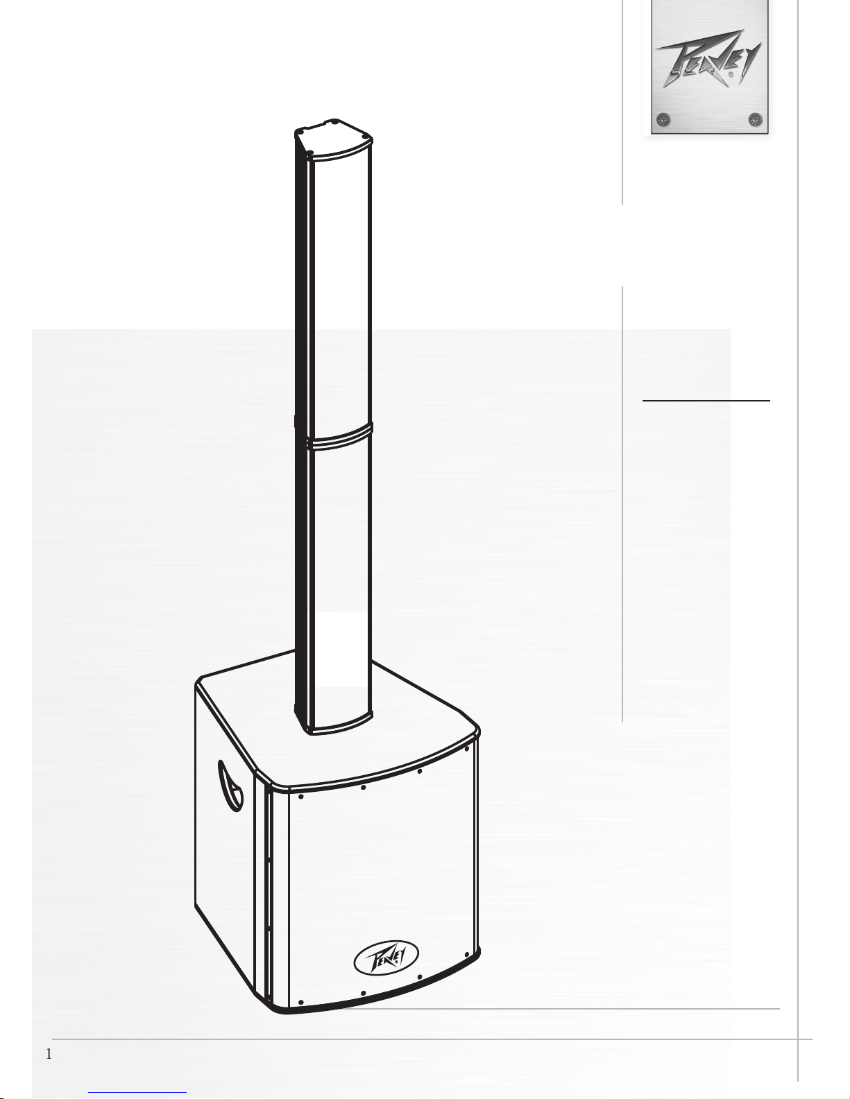
P™
Vertical Array Powered Speaker System
Congratulations on purchasing the Peavey P Vertical Array Powered Speaker System. is compact and powerful system is a perfect solution for the weekend warrior, singer songwriter or DJ.
FEATURES:
• Compact and portable design, with clear, powerful sound.
• 12" Powered Subwoofer
• Eight 3 1/2" drivers internally crossed over.
• 3 Channel input mixer with independant level control per channel.
• Channel 1 XLR/1/4" combi with mic/line pad switch.
• Channel 2 L/R 1/4" input
• Channel 3 L/R RCA Stereo inputs.
• Master Signal/Clip LED Indicator
• DSP voicing controls
• XLR line level out for linking systems
Description:
e compact and portable Peavey P Vertical Array Powered Speaker System, produces powerful and clear
audio, thanks to its 12"powered Sub and eight 3 1/2" drivers. e P is equipped with a 3 Channel input
mixer with independant level control per channel, Master Signal/Clip LED indicators, DSP voicing controls, and an XLR line level out for linking the P to other systems.
Installation Note:
is unit must have the following clearances from any combustible surface: top: 8", sides: 12", back: 12"
3
Page 4
P™
min max
min max
min max
LEVEL
LEVEL
LEVEL
LO CUT
FL AT
VOICE
FL AT
BOOST
LOW FREQ
HI FREQ
MIC
DSP
LINE 1
POWER
SIGNAL CLIP
TM
1
5
ON
4
AC INPUT
7
6
8
32 3 2
1
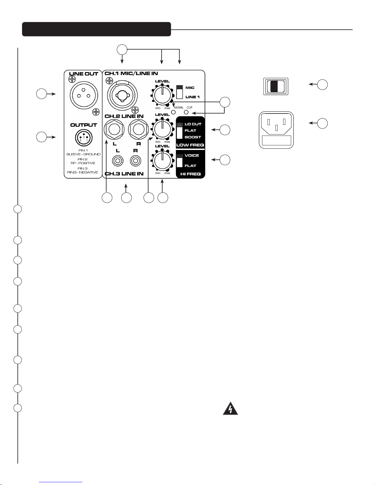
CHANNEL 1 INPUT: XLR combi 1/4" input with mic/line pad switch.
LEVEL: controls the gain level of Channel 1.
INPUT SELECT: allows user to select between MIC or LINE INPUT for Channel 1.
2
CHANNEL 2 INPUT: features 1/4" stereo inputs.
LEVEL: controls the gain of Channel 2.
3
CHANNEL 3 INPUT: Channel 3 features stereo RCA inputs.
LEVEL: controls the gain of Channel 3.
4
MASTER SIG/CLIP LEDs: these LEDs indicate whether or not a signal is present (SIG shines red), and if the signal is clipping
(Clip ashes red).
5
LINE OUT: non-powered XLR line level out for linking systems together.
6
OUTPUT: Connect your recording device to the output. is output is independent of master volume level
for optimized recording level.
7
LOW FREQUENCY SHAPE SWITCH: is three way switch allows shaping of the low frequencies by either boosting, leveling
or cutting the low frequency response.
9
10
HIGH FREQUENCY SHAPE SWITCH: is two way switch allows shaping of the high frequencies.
8
9
POWER SWITCH: To turn ON / OFF the P Vertical Array Speaker System.
4
Page 5

P™
10
AC INPUT/ Fuse In IEC Jack: 100V-240V~50Hz/60Hz
Connect to main power (100~240V AC) with the included power chord. It is built-in with one electrical
fuse. If damaged, please replace the fuse with the same specication.
Fuse In IEC Jack
To replace the fuse, be sure to remove the IEC power cord from the IEC socket. e fuse holder tray is located beneath the IEC
socket cavity. Pry the fuse holder tray out with a small at blade screwdriver placed under the center of the top edge of the fuse tray,
and gently lever the fuse tray out. e fuse is held in a clip in the fuse tray, and should be removed and replaced with a fresh 5 X
20mm 250V type fuse of the appropriate current rating. A spare fuse should be located in a hollow compartment in the fuse tray,
below and behind the clip, this would be the one that is NOT clipped into the fuse tray clips.
en, once the fresh fuse has been put in place, re-insert the fuse tray into the IEC connector assembly, and make sure it is fully
seated and ush with the outside of the IEC connector assembly.
It is recommended that to assure future convenience of having a spare, that a spare fuse be obtained and placed in the hollow compartment at the earliest convenient time.
5
Page 6

Cautions
Cautions
e unit must be disconnected from the AC power source before any work is done on it. Refer all servicing to
qualied service personnel.
e back plate can become hot to the touch. Do not block or cover the fan or the exhaust louvers from ventilation. ere must be a minimum of 4” of space behind the fan. Do not allow the airow to be become blocked
by objects such as curtains or drapes, thermal building insulation, etc. It is recommended that the rear of the
P2™ not be placed in a closed space or a space that has no fresh, cool airow.
Be sure to keep the microphone away from the front of the speaker aer connecting it to the input, and while
setting the microphone level, or very loud feedback will occur! Damage to the system is likely if this occurs!
DO NOT connect the inputs of the P™ to the output of a power amplier. e inputs are meant to be driven
from a line-level strength signal.
DO NOT remove the protective metal grille.
WARNING! e P™ is very ecient and powerful! is sound system can permanently damage hearing! Use
extreme care setting the overall maximum loudness!
e apparent sound level of the P can be deceiving due to its clear, clean sound output. e lack of distortion or
obvious distress can make the sound level seem much lower than it actually is. is system is capable of SPL in
excess of 122 dB at 1 M from the speaker!
WARNING! Due to the nature of the plug in connections of the array speakers to the Sub, please be careful to
always place the P on a at surface (no more than 5°angle).
P™ System Connection
Connecting AC Power To e P
e P comes with an 6-foot IEC connection AC power cord. If you are using an extension cord or power strip
with this powered speaker, make sure it is of good quality and of a sucient current capacity to maintain safety
and maximize the power output capability of the P. For maximum undistorted output, do not connect any
other device to the same extension cord that the P is connected to. Do not exceed the rated current capacity of
the extension cord with the sum total of all units connected to it.
When rst plugging in the AC cord, make sure the power switch is in the O position, and then turn it On only
once the power cord has been connected.
Power on sequence:
1. Minimize the output level of mixer (or other audio source).
2. Turn on the audio source devices, such as CD players, mixers, instruments.
3. Turn on the P. Aer that, the output level can be increased step by step.
Power o sequence:
1. Turn o the P.
2. Turn o all the audio source devices.
6
Page 7

P™ Input Connection
Connecting multiple units together.
LINE OUT
OUTPUT
3
1
2
PIN 1
SLEEVE - GROUND
PIN 2
TIP - POSITIVE
PIN 3
RING - NEGATIVE
CH.1 MIC/LINE IN
CH.2 LINE IN
L
LRR
CH.3 LINE IN
LEVEL
min max
LEVEL
min max
LEVEL
min max
MIC
LINE 1
SIGNAL CLIP
DSP
LO CUT
FL AT
BOOST
LOW FREQ
VOICE
FL AT
HI FREQ
PI ANO
GU ITAR
LINE OUT
OUTPUT
3
1
2
PIN 1
SLEEVE - GROUND
PIN 2
TIP - POSITIVE
PIN 3
RING - NEGATIVE
CH.1 MIC/LINE IN
CH.2 LINE IN
L
LRR
CH.3 LINE IN
LEVEL
min max
LEVEL
min max
LEVEL
min max
MIC
LINE 1
SIGNAL CLIP
DSP
LO CUT
FL AT
BOOST
LOW FREQ
VOICE
FL AT
HI FREQ
LINE OUT
OUTPUT
2
PIN 1
SLEEVE - GROUND
PIN 2
TIP - POSITIVE
PIN 3
RING - NEGATIVE
CH.1 MIC/LINE IN
CH.2 LINE IN
3
1
CH.3 LINE IN
L
LRR
LEVEL
min max
LEVEL
min max
LEVEL
min max
MIC
LINE 1
SIGNAL CLIP
DSP
LO CUT
FL AT
BOOST
LOW FREQ
VOICE
FL AT
HI FREQ
UNIT #1 UNIT #2
7
Page 8

P™ System Connection
Connecting a Signal to the P
ere are a variety of ways to input a signal to the P.
e inputs provide either a balanced mic- or line-level input, allowing the use of a 1/4” TRS (ring-tip-sleeve)
type phone plug, a male XLR plug, 1/4" stereo* jacks (channel 2), or RCA connectors (channel 3).
Do not connect cables to the jacks while the unit is ON and the Level knob is turned up! While a standard
single-ended 1/4” phone plug-equipped cable will work well and the balanced input circuitry will provide some
interference rejection, a balanced cable using either the balanced TRS 1/4” phone plug or the XLR plug will provide superior interference rejection and performance.
Sometimes, with dicult interference problems, it will be helpful to li the shield ground ( Pin #1 of an XLR) of
a balanced cable at the P end. Check any input changes carefully, always turning the Level control down before
plugging and unplugging cables.
Use of high quality, premium cables is recommended for the P, as these usually have better shielding and materials and will provide greater long-term reliability. e best option is a shielded balanced cable no longer than
necessary to reach the P. It is usually a good idea to leave some slack at the input to the P and also to tape the
cables down or run them under a cable guard to avoid anyone tripping over them or pulling the P over when
stand mounted.
Level Control Adjustment
e P is equipped with Level controls on the input to facilitate use in many dierent applications. With the
Level control adjusted fully clockwise, gain is at maximum and the input sensitivity is 1.0 V RMS for full-rated
output with the line level position of the Mic/Line switch. When driving the P from an external mixer, it may
be advantageous to reduce the input sensitivity by turning the Level control to the halfway point. e P2 will
now more closely match a typical power amp.
If the mixing board indicates clipping of its output signals, then all of the P power capability is not being utilized
cleanly. Clipping the signal before it gets to the P is not optimal. Reduce the mixer output level and turn up the
Level control/s on the P.
When rst turning on the sound system, switch on all upstream electronics rst, then the P with its Level
control fully counterclockwise (all the way down). Begin checking levels with the mixer output level controls all
the way down, and bring them up slowly with the P Level control/s set to the desired setting (one-third way up
recommended to start).
It is not good practice to turn the Level control/s on the P all the way up and then try to control level only from
the mixer, this approach would tend to pick up excess noise. Best practice would be to run a “hot” signal from
the mixer down the cable to the P, and then turn the P Level control up only as much as necessary to reach full
desired output. With this approach, it is necessary to verify the mixer output is not clipping.
Disconnecting AC Power to the P
We recommend that the Power switch (9) be used to turn the unit o rst, and then the AC power cord can be
removed, this minimizes stress to the power ampliers and the transducers from turn-o transients. e power
switch has an arc suppression capacitor to help during turn-o, and tends to make a clean disconnect from the
AC power, while the power cord IEC connector can make intermittent contact before nally becoming fully disconnected, e.g., as when wiggling the cord.
8
Page 9

Troubleshooting
No Output at All
First, make sure the unit has AC power and is turned ON. Make sure the LCD on the power amp module is
illuminated.
If not, make certain the ON/OFF switch (9) is in the ON position and check the IEC power cord connection
(10) by ensuring it is fully engaged and seated. Make certain the AC line cord is plugged into a working AC
outlet. Finally, check the fuse (10). (See Fuse In IEC Jack section, for safety instructions.)
Once assured your unit is getting AC power, check that the P is getting a signal. Temporarily disconnect the
cable running to its inputs and connect it to some other device capable of reproducing the signal (i.e., a power
amp and speaker). If this produces a signal, make sure that all Level controls being used have been turned up to
a satisfactory level (one-third to halfway).
If the P has been subjected to direct sunlight or excessive heat, the built-in thermal protection may have been
triggered. If so, turn o the P and let it cool for a sucient amount of time.
If there is still no output, contact your authorized Peavey dealer or the Peavey International Service Center.
Hum or Buzz
If the P is producing a hum or buzz, this can be AC outlet related. Try plugging the P into a dierent AC outlet. Sometimes, if a dierent circuit (breaker) is used for the mixer and for the P, it can cause hum problems.
Unless it is not practical, it is best to use the same wall outlet (breaker) to supply power to both the mixer and
the powered speaker.
Ensure that shielded cables have been used to route the signal to the P input. If speaker cables with 1/4” plugs
are used as input cables instead of shielded cables, they will be prone to hum or buzz.
Hum may be ground loop related. It may be helpful to li the shield ground (Pin #1) on a balanced cable at the
P end. Check any input changes carefully by rst turning down the Level control, before plugging and unplugging cables, or liing the shield ground at the speaker end.
Check to make sure light dimmers are not on the same circuit as the P, the mixer or any source devices. If
light dimmers are used, then it may be necessary to turn them full ON or full OFF to eliminate or reduce hum.
is is a typical AC wiring/light dimmer interference problem, not a design aw of the P.
e third wire (ground plug) on the AC plug should NEVER be removed or broken o, as this is a potential
safety hazard.
Distorted or Fuzzy Sound
First, ensure the mixer (signal source) is not clipping or being overdriven. Make sure the Level control on the
P has not been set too low. Check that the input plug is fully seated in the input jack on the rear panel of the
P. Ensure that a power amp has not been plugged into the input jack of the P. If an extension cord is being
used to provide the AC power to the unit, insure that it is of sucient current capacity and that it is not also being used to supply power to any other device.
e P has built-in frequency shaping to smooth and extend the natural response of the speakers. If excessive
additional bass boost or HF boost have been added externally to the P, it could cause premature overload at
9
Page 10

high SPL. Reduce the amount of any external (mixer, rack) EQ and see if that clears up the distortion.
Care and Maintenance
Your P is a sturdy and durable product and will provide years of reliable use if properly cared for. Use common
sense and read the safety warnings to avoid hazardous operating conditions.
e unit must be disconnected from the AC power source before any work is done on it. Refer all servicing to
qualied service personnel.
Sunlight/Heat
Avoid prolonged exposure to direct sunlight, as this may cause the unit to overheat and thermally shut o.
Excessively hot operating conditions can also cause a thermal shutdown.
Do not store in extremely hot or cold conditions or extremely high humidity. Always allow unit to come to room
temperature before use.
Cleaning
Never clean the P while plugged in or turned ON! When the unit has been fully disconnected from AC power
sources, use a dry cloth to remove soil or other dirt. Never use strong solvents on the P, as they could damage
the cabinet. Do not allow ANY uids to drip inside the P.
10
Page 11

P™ Specifications
Power Supply: 100-240VAC~ 50/60Hz
Power Consumption: 230W
Dimensions: WxDxH: 17.25"x 18.9" x 68" (438.15mm x 481mm x 1727mm)
Net Weight: 76 lbs (34.5 kg)
Sub Weight: 57.1 lbs (25.9 kg)
Satellite Weight (x 2): 18.5 lbs (8.4 kg)
Power Output: Woofer:130 watts peak available power, 65 watts Cont. into 8 Ohms ( THD 1 % )
Tweeter:120watts peak available power, 60 watts Cont. into 8 Ohms ( THD 1 % )
Frequency Response: 56 Hz ~ 20K Hz ( +/- 10 dB )
Crossover Frequency: Sub to pole: 150Hz
Top module to bottom module: 2 kHz
Max SPL: 122dB
Input Sensitivity: MIC:30mV +/-5mV
LINE:1V +/-0.1V
Dispersion: 50 degrees Horizontal by 35 degrees Vertical
Nominal Impedance: 8 Ohms
S. P. L.: 93dB ±3dB (1w/1m)
Woofer: 12 inch X1
Tweeters: 3 1/2 inch X8
11
Page 12

Logo referenced in Directive 2002/96/EC Annex IV
The bar is the symbol for marking of new waste and
13 August 2005
Warranty registration and information for U.S. customers available online at
Features and specications subject to change without notice.
Peavey Electronics Corporation 5022 Hartley Peavey Drive Meridian, MS 39305 (601) 483-5365 FAX (601) 486-1278
12
www.peavey.com
www.peavey.com/warranty
or use the QR tag below
(OJ(L)37/38,13.02.03 and defined in EN 50419: 2005
is applied only to equipment manufactured after
 Loading...