

Page 1
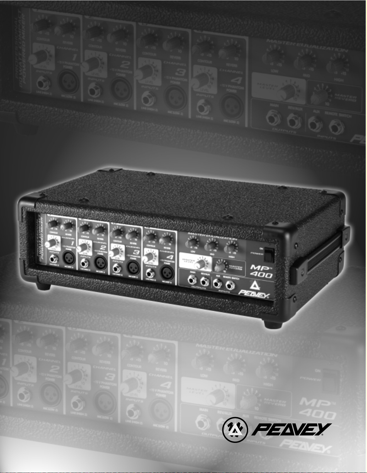
MP 400
Professional
80 Watt Compact
Powered Mixer
™
Operating Guide
Page 2
2
Intended to alert the user to the presence of uninsulated “dangerous voltage” within the product’s
enclosure that may be of sufficient magnitude to constitute a risk of electric shock to persons.
Intended to alert the user of the presence of important operating and maintenance (servicing)
instructions in the literature accompanying the product.
CAUTION: Risk of electrical shock — DO NOT OPEN!
CAUTION: To reduce the risk of electric shock, do not remove cover. No user serviceable parts inside. Refer
servicing to qualified service personnel.
WARNING: To prevent electrical shock or fire hazard, do not expose this appliance to rain or moisture. Before
using this appliance, read the operating guide for further warnings.
Este símbolo tiene el propósito, de alertar al usuario de la presencia de “(voltaje) peligroso” sin aislamiento dentro de la caja del producto y que puede tener una magnitud suficiente como para constituir
riesgo de descarga eléctrica.
Este símbolo tiene el propósito de alertar al usario de la presencia de instruccones importantes sobre la
operación y mantenimiento en la información que viene con el producto.
PRECAUCION: Riesgo de descarga eléctrica ¡NO ABRIR!
PRECAUCION: Para disminuír el riesgo de descarga eléctrica, no abra la cubierta. No hay piezas útiles dentro.
Deje todo mantenimiento en manos del personal técnico cualificado.
ADVERTENCIA: Para evitar descargas eléctricas o peligro de incendio, no deje expuesto a la lluvia o humedad
este aparato Antes de usar este aparato, Iea más advertencias en la guía de operación.
Ce symbole est utilisé dans ce manuel pour indiquer à l’utilisateur la présence d’une tension dangereuse
pouvant être d’amplitude suffisante pour constituer un risque de choc électrique.
Ce symbole est utilisé dans ce manuel pour indiquer à l’utilisateur qu’il ou qu’elle trouvera d’importantes
instructions concernant l’utilisation et l’entretien de l’appareil dans le paragraphe signalé.
ATTENTION: Risques de choc électrique — NE PAS OUVRIR!
ATTENTION: Afin de réduire le risque de choc électrique, ne pas enlever le couvercle. Il ne se trouve à l’intérieur
aucune pièce pouvant être reparée par l’utilisateur. Confiez I’entretien et la réparation de l’appareil à un réparateur
Peavey agréé.
AVERTISSEMENT: Afin de prévenir les risques de décharge électrique ou de feu, n’exposez pas cet appareil à la
pluie ou à l’humidité. Avant d’utiliser cet appareil, lisez attentivement les avertissements supplémentaires de ce
manuel.
Dieses Symbol soll den Anwender vor unisolierten gefährlichen Spannungen innerhalb des Gehäuses
warnen, die von Ausreichender Stärke sind, um einen elektrischen Schlag verursachen zu können.
Dieses Symbol soll den Benutzer auf wichtige Instruktionen in der Bedienungsanleitung aufmerksam
machen, die Handhabung und Wartung des Produkts betreffen.
VORSICHT: Risiko — Elektrischer Schlag! Nicht öffnen!
VORSICHT: Um das Risiko eines elektrischen Schlages zu vermeiden, nicht die Abdeckung enfernen. Es befinden
sich keine Teile darin, die vom Anwender repariert werden könnten. Reparaturen nur von qualifiziertem
Fachpersonal durchführen lassen.
ACHTUNG: Um einen elektrischen Schlag oder Feuergefahr zu vermeiden, sollte dieses Gerät nicht dem Regen
oder Feuchtigkeit ausgesetzt werden. Vor Inbetriebnahme unbedingt die Bedienungsanleitung lesen.
Page 3

MP™400
Powered Mixer
Thank you for purchasing the Peavey MP
™
400! The MP™400 is a four-channel, powered mixer
packed into an amazing compact package. Featuring only the essential requirements for a sound
reinforcement mixer, the MP 400 is a breeze to operate and a joy to own. Quality semiconductor
components lend a hand to achieve the excellent audio characteristics and reliable service
that has made the MP Series Mixer so well known.
The MP 400 boasts four discrete channels, each with high and low impedance inputs, a Contour
high frequency EQ control, and Reverb and Level controls. The master section offers a three-band
equalizer, Master Level and Reverb controls, 1/4" Main and Reverb/Aux Outputs, Aux Input, and
Remote Switch Input.
The following guide explains the MP 400 features and the proper operation of each. Refer to the
diagrams in each section to locate each feature by its designated number. Throughout this guide,
related features will sometimes refer you to another feature using this number system. Let’s begin
by listing the main features of the MP 400.
FEATURES:
• Four total input channels
• Reverb control on each channel
• Contour high frequency equalizer on each channel
• 1/4" and XLR inputs on each input channel
• 1/4" Main Output
• 1/4" Aux/Reverb Output
• 1/4" Aux Input
• 1/4" Remote Switch for reverb defeat
• Master Three-band Equalizer
• Master Level and Reverb controls
• 80 W power amp
3
ENGLISH
Page 4

POWER
This section describes the proper application of AC power to your MP 400. To insure the safety
of you and your MP 400, please pay close attention to any designated cautions.
REAR PANEL
1. IEC POWER SOCKET:
With the Power Switch (#2) in the off (O) position, plug the power cord into this connector
prior to plugging it into your AC power source. Always insure that proper grounding practices
are utilized. Damage to the equipment may occur if improper line voltage is used (see voltage
marking on unit). Never remove or cut the ground pin of the line cord plug.
NOTE: FOR UK ONLY
As the colors of the wires in the mains lead of this apparatus may not correspond with the
colored markings identifying the terminals in your plug, proceed as follows: (1) The wire which
is colored green and yellow must be connected to the terminal which is marked by the letter
E, or by the earth symbol, or colored green or green and yellow. (2) The wire which is colored
blue must be connected to the terminal which is marked with the letter N, or the color black.
(3) The wire which is colored brown must be connected to the terminal which is marked with
the letter L or color red.
2. POWER SWITCH (See front panel diagram next page)
Place this switch in the “ON” position to turn the unit on.
3. POWER LED (See front panel diagram next page)
Illuminates when AC power is being supplied to the mixer.
SPEAKER CONNECTIONS
This section will help you locate the two speaker output jacks on the rear of your MP 400.
WARNING: NEVER ALLOW YOUR TOTAL SPEAKER IMPEDANCE TO DROP BELOW
THE MINIMUM IMPEDANCE OF 4 OHMS.
4. SPEAKER OUTPUTS
Two parallel 1/4" jacks are provided at the output of the power amplifier for ease of speaker
connection. Minimum speaker impedance (min. load) is 4 ohms.
4
1
4
Page 5
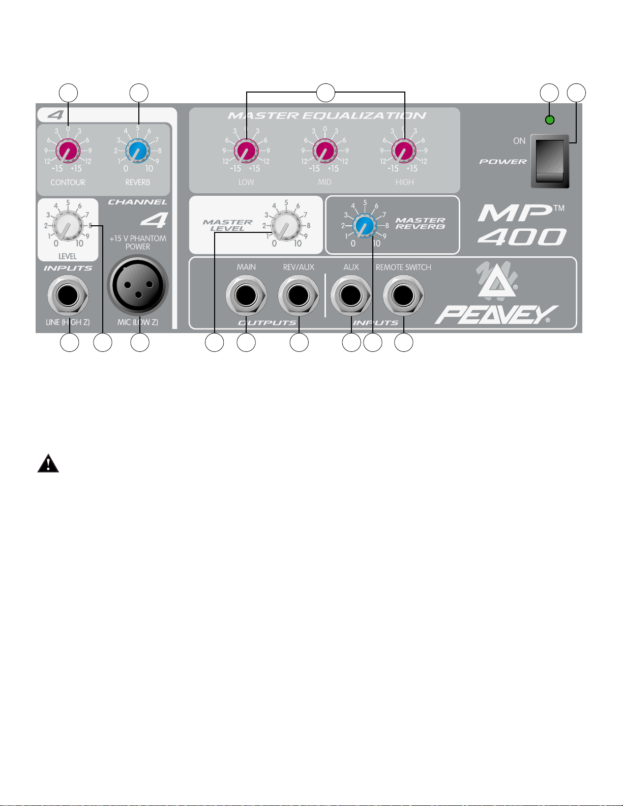
CHANNEL FEATURES (CHANNELS 1-4)
The following section describes channels 1-4. Each of these input channels is identical.
5. MIC (LOW Z) INPUT
XLR balanced low impedance channel input optimized for a microphone or other low
impedance source. Pin 2 is the positive input. This connector has +15V phantom power
supply on Pins 2 and 3 at all times (Pin 1 is the ground reference).
WARNING: BECAUSE THE LOW-Z INPUTS HAVE PHANTOM POWER, ONLY CONNECT
MICROPHONES OR PRODUCTS WITH A BALANCED OUTPUT TO PREVENT DAMAGE.
IF YOU ARE UNSURE, PLEASE CHECK THE PRODUCT’S OPERATING INSTRUCTIONS.
6. LINE (HIGH Z) INPUT
1/4" unbalanced input that accepts line level sources equipped with a 1/4" plug (TS). The two
inputs (XLR and 1/4") cannot be used simultaneously.
7. LEVEL
Sets the level of the individual channel in the mix.
8. REVERB
Sets the level of the internal reverb for the channel and must be used in conjunction with the
master reverb level. It is post gain and will be affected by the LEVEL (7) adjustment. The
Reverb/Aux control also determines the level of signal sent to the Effects Output (14).
9. CONTOUR
A shelving type of active tone control that varies the treble frequency level ±15 dB at 10 kHz.
It is designed to remove noise or to add brilliance to the signal, depending on the quality of
the source.
5
6
5 13 14 15 16
3
9 8
2
11107
12
Page 6

MASTER FEATURES
10. MASTER LEVEL CONTROL
Controls the overall volume level of the system.
11. MASTER REVERB CONTROL
Controls the amount of reverb that will be heard in the main mix.
12. MASTER EQUALIZATION
Provides ±15 dB equalization at each center frequency. EQ boost is obtained by moving a
particular EQ band’s control above the “0” position. EQ cut is obtained by moving a particular
EQ band’s control below the “0” position. The following list describes each EQ control and its
center frequency.
Low - shelving type - 80 Hz
Mid - peak type - 1 kHz
High - shelving type - 10 kHz
OPERATION NOTE: This equalizer is designed to provide room equalization, feedback
control and system tone control. No amount of equalization will correct the response curve
of a poor loudspeaker. Always begin with all controls in the “0” position and avoid excessively
cutting large segments of the audio passband, which would limit the system’s dynamic range.
13. MAIN OUTPUT
1/4" unbalanced output that can be used as a source for an external amplifier/speaker
system feed to other mixers or a tape deck.
14. REVERB/AUX OUTPUT
Plugging into this mono (TS) 1/4" output allows you to utilize external effects devices. In order
to return the signal from the external effects unit, use the Aux Input (15). Simply turn the
Reverb Master down to defeat the Internal Reverb if desired.
15. AUX INPUT
Use this mono 1/4"(TS) input to insert a line-level signal into the main mix. This signal can
originate from a variety of sources including instrument/mic preamps, external effects
(see #14), and even an additional sub mixer. This input bypasses the reverb and can be
controlled by the Master EQ and Level.
16. REVERB FOOTSWITCH
Provided for connection of the optional remote footswitch (5100). The footswitch is used to
activate/defeat the reverb.
6
Page 7

Note: All specifications are typical unless otherwise noted.
0 dBV = 1 Volt RMS
0 dBu = .778 Volts RMS
All specs are referenced to nominal output level (0 dBV)
unless otherwise noted.
All measurements are wideband 20 Hz to 20 kHz unless
otherwise noted.
All control settings are nominal (50% rotation) unless
otherwise noted.
CHANNEL:
Equivalent Input Noise
-116 dBV @ 40 dB Max Gain
Frequency Response:
(To Speaker Outputs)
±3 dB 20 Hz to 20 kHz
Distortion: @ (1 kHz):
Less than .009%
Input Impedance:
Low Z Bal. 2K ohms
1/4" Mic Input 22K ohms
CHANNEL EQ:
Contour EQ:
±15 dB @ 10 kHz Minimum
Center Detent flat ±2 dB
Nominal Channel Gain:
Line = 0 dB
Low Z = 30 dB
Maximum Channel Gain:
Low Z = 50 dB
Line = 19 dB
Nominal Input Level:
Low Z = -30 dB
Line = 0 dB
Minimum Input Level:
Low Z = -50 dB
Line = -19 dB
Maximum Input Level:
Low Z =-11 dB
Line = +28 dB
Phantom Power:
+15 VDC
MASTER:
Gain
Main: = 10 dB (variable)
High EQ:
± 15 dB @ 12 kHz Minimum
Center Detent flat ±2 dB
Mid EQ:
± 15 dB @ 1 kHz Minimum
Center Detent flat ±2 dB
Low EQ:
± 15 dB @ 60 HZ Minimum
Center Detent flat ±2 dB
Maximum Output Level:
Main: = + 18 dBV (8.0 V RMS)
Effects: = + 18 dBV (8.0 V RMS)
Nominal Headroom:
Main: = 18 dB
Effects: = 18 dB
Output Impedance:
Main: = 100 ohms
Effects: = 100 ohms
Output Noise:
Residual: -95
(Master Level Down)
Bus: -93
(Master Nominal, All Channel Level Full CCW, Reverb Level Down)
Nominal: -78
(All Controls Nominal, Low Z Input Terminated 150 Ohms)
Signal to noise ratio:
Microphone input to speaker output (>80 dB)
Frequency Response: 20 Hz to 20 kHz
SYSTEM DYNAMIC RANGE:
95 dB
POWER AMP SECTION:
Frequency Response:
+0, -3 dB, 30 Hz to 28 kHz @ Rated Power
RATED POWER AND LOAD:
80 W RMS into 4 ohms
55 W RMS into 8 ohms
THD less than .5% Mic input to speaker output 1 kHz at rated
power. Speaker system Impedance: 4 ohms minimum.
Power Requirements:
150W @ 100V, 120V, 230 VAC 50/60 Hz.
7
MP™400 SPECIFICATIONS
Specifications are subject to change without notice.
Page 8
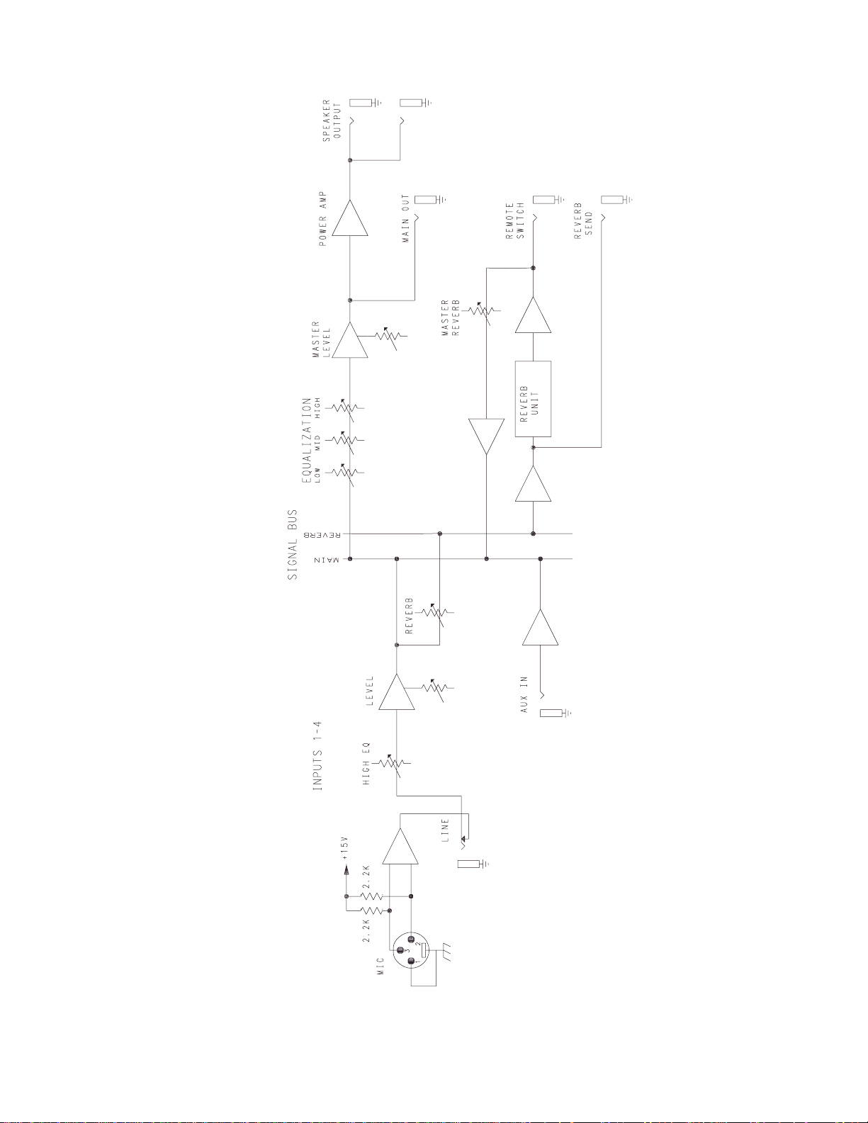
8
MP 400 BLOCK DIAGRAM
Page 9
9
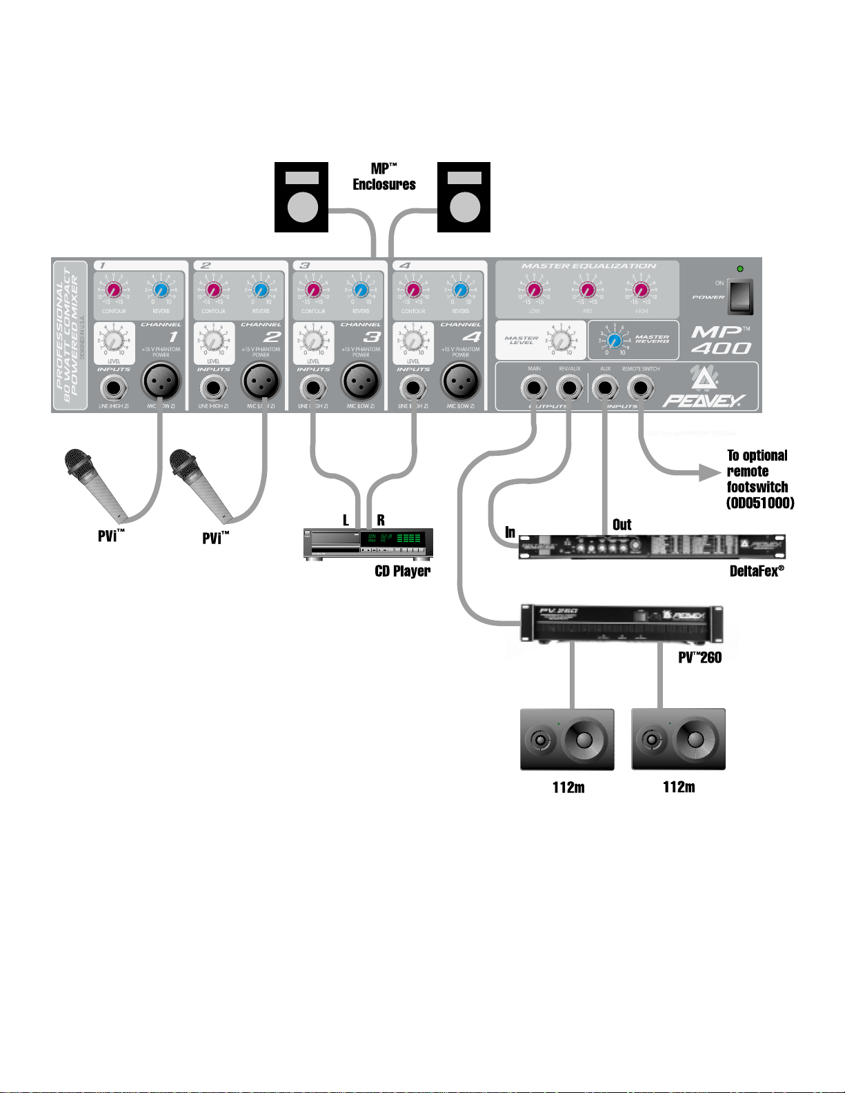
MP™400 RECOMMENDED HOOKUP
Page 10

MP™400
Power-Mixer
Danke, daß Sie sich für den Peavey MP
™
400 entschieden haben! Der MP™400 ist ein 4-Kanal
Power-Mixer, der in einem erstaunlich kleinen Gehäuse untergebracht ist. Ausgestattet nur mit den
nötigsten Anforderungen an einen Power-Mixer, ist der MP 400 kinderleicht in der Bedienung und
bereitet seinem Besitzer die reinste Freude. Hochwertige Halbleiterkomponenten verhelfen dem
MP 400 zu seinen exzellenten Klangwerten und seiner Zuverlässigkeit, die die MP Serie Mischpulte
so bekannt gemacht haben.
Der MP 400 wartet mit 4 diskret-aufgebauten Kanälen auf; jeder mit 2 Eingängen (high- / lowImpedanz), einem Contour Equalizer für die Höhen, Reverb und Lautsärke-Regler. Die MasterSektion ist mit einem 3-Band Equalizer, Master Level und Reverb Reglern, 1/4" Reverb- und Aux Ausgängen, Aux-Eingang und einem Fußschalter-Eingang ausgestattet.
Die folgende Bedienungsanleitung erklärt die Austattungsmerkmale des MP 400 und deren
Bedienung. In den Zeichnungen finden Sie die einzelnen Sektionen und deren Bedienelemnte
anhand der Nummern. Im Laufe der Bedienungsanleitung verweisen wir Sie auf weitere
Bedienhinweise, die im Zusammenhang stehen. Sie finden diese auch anhand des
Numerierungssystems. Fangen wir mit der Aufzählung der wichtigsten Austattungsmerkmale des
MP 400 an.
ÜBERSICHT:
• 4 volle Eingangskanäle
• Reverb-Regler in jedem Kanalzug
• Contour Equalizer für die Höhen in jedem Kanalzug
• 1/4" Klinke und XLR Eingänge in jedem Kanalzug
• 1/4" Klinke Main Ausgang
• 1/4" Klinke Aux/Reverb Ausgang
• 1/4" Klinke Aux Eingang
• 1/4" Klinke Fußschalter-Eingang zum Ein- /Ausschalten des Reverbs
• 3-Band Equalizer in der Mastersektion
• Master Level- und Reverb Regler
• 80W Endstufe
10
DEUTSCH
Page 11

POWER
Dieser Abschnitt beschreibt den richtigen Anschluß Ihres MP 400 an eine WechselstromSpannungsquelle. Um Ihre und die Sicherheit Ihres MP 400 zu gewährleisten, achten Sie bitte auf
die Warnhinweise.
GERÄTERÜCKSEITE
1. EURO-NETZBUCHSE
Stecken Sie das Netzkabel bei ausgeschaltetem Gerät (Netzschalter(#2) in der Aus (0)
Position) in das Gerät, bevor Sie es mit einer Steckdose verbinden. Stellen Sie sicher, daß
die richtige Erdung gewährleistet ist. Legen Sie eine falsche Netzspannung an, besteht die
Gefahr, dass das Gerät beschädigt wird (beachten Sie die Spannungsangabe an dem Gerät).
Entfernen Sie keinesfalls den Erdungspol des Netzsteckers.
2. N ETZSCHALTER (Siehe Frontskizze auf der nächsten Seite)
Bringen Sie den Schalter in die „EIN" Stellung, um das Gerät einzuschalten.
3. POWER LED (Siehe Frontskizze auf der nächsten Seite)
Leuchtet, wenn das Gerät mit Strom versorgt wird
LAUTSPRECHERANSCHLÜSSE
Dieser Abschnitt wird Ihnen dabei helfen die Klinkenbuchsen für den Anschluß der Lautsprecher an
der Rückseite Ihres MP 400 zu finden.
Warnung: Achten Sie darauf, daß die Gesamtimpedanz der angeschlossenen
Lautsprecher niemals unter 4 Ohm fällt.
4. LAUTSPRECHERAUSGÄNGE
Zwei parallel-geschaltete 1/4" Klinken sind zum einfacheren Anschluß, am Ausgang der
Endstufe angebracht. Die minimale Impedanz (Mindestlast) beträgt 4 Ohm.
11
1
4
Page 12
KANALAUSTATTUNG (KANÄLE 1-4)
Der folgende Abschnitt beschreibt die Kanäle 1-4. Diese Eingangskanäle sind identisch.
5. MIC (LOW Z) INPUT
Symmetrische XLR-Eingang zum Anschluß niederohmiger Mikrofone oder anderer
niederohmiger Signalquellen. Pin 2 ist der Pluspol. Dieser Eingang wird immer mit +15V
Phantomspeisung zwischen Pin 2 und 3 versorgt (Pin 1 ist Masse).
WARNUNG: DA DIESE NIEDEROHMIGEN EINGÄNGE IMMER MIT PHANTONSPANNUNG
VERSORGT WERDEN, SCHLIESSEB SIE BITTE NUR MIKROPHONE ODER GERÄTE MIT
SYMMETRISCHEN AUSGÄNGEN AN, UM SCHÄDEN ZU VERMEIDEN. FALLS SIE SICH
NICHT SICHER SIND, LESEN SIE BITTE DIE GEBRAUCHSANWEISUNG DES
JEWEILIGEN GERÄTS.
6. Line (HIGH Z) Input
Unsymmetrische 1/4" Klinkeneingang für hochpegelige Signalquellen mit 1/4"
Klinkenausgängen. Die beiden Eingänge (XLR und Klinke) können nicht gleichzeitig benutzt
werden.
7. LEVEL
Regelt die individuelle Lautstärke des Kanals in der Mischung.
8. REVERB
Regelt den Hallanteil des eingebauten Hallgeräts für den Kanal und muss mit dem
Master-Reverb-Regler benutzt werden. Das Originalsignal wird nach dem Levelregler (7)
abgegriffen und wird daher von diesem beeinflußt. Der Reverb/Aux Regler bestimmt
außerdem den Pegel, der zum Effekt-Ausgang geschickt wird (14).
9. CONTOUR
Ein Shelving-EQ regelt die Höhen bei 10 kHz um ±15 dB. Er ist so ausgelegt, daß er
Störgeräusche absenkt, oder das Signal „brillanter" macht, je nach Qualität der Quelle.
12
6
5 13 14 15 16
3
9 8
2
11107
12
Page 13

MASTER BEREICH
10. MASTER LEVEL CONTROL
Regelt die Gesamtlautstärke des Systems
11. MASTER REVERB CONTROL
Regelt den Hallanteil der Gesamtmischung
12. MASTER EQ
Regelt um ±15 dB im Bereich der Center-Frequenz. Eine Anhebung des entsprechenden
Frequenzbereichs wird durch Drehung des entsprechenden Reglers über die „0"-Position
bewirkt. Eine Absenkung des entsprechenden Frequenzbereichs wird durch Drehung des
entsprechenden Reglers unter die „0"-Position bewirkt. Die folgende Tabelle beschreibt jeden
EQ-Regler und dessen Center-Frequenz.
Low – shelving type – 80 Hz
Mid – peak type – 1 kHz
High - shelving type – 10 kHz
HINWEIS: Der Equalizer ist für den Ausgleich des Raumklangs, die Unterdrückung von
Rückkopplungen sowie die Beeinflussung des Gesamtklangs ausgelegt. Kein noch so starker
Einsatz des Equalizers kann den Frequenzgang eines schlechten Lautsprechers ausgleichen.
Bei der Klangeinstellung sollten Sie immer von der „0"-Position ausgehen. Drehen Sie
möglichst nicht in extreme Positionen, da übermäßige Absenkung die Dynamik des Systems
begrenzt.
13. MAIN OUTPUT
Unsymmetrische 1/4" Klinkenausgänge, deren Signal auch zur Speisung externer
Verstärker/Lautsprecher, anderer Mischpulte oder Kassettenrecorder dienen kann.
14. REVERB/AUX OUTPUT
Dieser 1/4" Klinkenausgang (Mono) dient zur Speisung externer Effektgeräte.
Nutzen Sie den Aux-Eingang (15), um das Signal des Effektgeräts in das Mischpult zu führen.
Drehen Sie einfach den Reverb Master Regler ganz zu, um das eingebaute Hallgerät zu
unterdrücken.
15. AUX INPUT
Mono 1/4"Klinkeneingang zum einspielen eines Line-Signals in die Gesamtmischung. Dieses
Signal kann verschiedene Quellen haben, einschließlich eines Instrumenten/Mikrophon
Vorverstärkers, Externer Effektgeräte (s. #14) oder gar eines zusätzlichen Sub-Mixer. Dieser
Eingang umgeht den Hall und kann über den Master-EQ und Level geregelt werden.
16. REVERB FOOTSWITCH
Klinkenbuchse zum Anschluß eines optionalen Fußschalters (5100), der das eingebaute
Effektgerät ein- oder ausschaltet.
13
Page 14

Hinweis: Alle technischen Daten sind typisch, sofern nicht
anders angegeben.
0 dBV = 1 Volt RMS
0 dBu = 0,778 Volt RMS
Alle Daten beziehen sich auf die Nennausgangsleistung
(0 dBV), sofern nicht anders angegeben.
Alle Messungen erfolgten über die gesamte Bandbreite
von 20 Hz bis 20 kHz, sofern nicht anders angegeben.
Alle Regler auf Nennstellung (Mittelstellung), sofern
nicht anders angegeben.
KANAL:
Äquivalentes Eingangsrauschen
-116 dBV bei 40 dB Maximum Gain
Frequenzgang:
(An den Lautsprecherausgängen)
±3 dB 20Hz – 20 kHz
Verzerrung bei 1 kHz:
weniger als 0,009%
Eingangsimpedanz:
XLR Symmetrischer Eingang : 2 kOhm
1/4" Klinken Eingang : 22 kOhm
KANAL EQ:
Contour EQ:
±15 dB bei 10 kHz
Abweichung in Mittelstellung ±2 dB
Nennpegel im Kanal:
Line = 0 dB
Low Z = 30 dB
Maximalpegel im Kanal:
Low Z = 50 dB
Line = 19 dB
Eingangs-Nennpegel:
Low Z = -30 dB
Line = 0 dB
Minimale Eingangsempfindlichkeit:
Low Z = -50 dB
Line = -19 dB
Maximaler Eingangspegel:
Low Z = -11 dB
Line + 28 dB
Phantomspeisung:
+15 VDC
MASTER:
Main Gain:
10 dB (regelbar)
High EQ:
±15 dB bei 12 kHz
Abweichung in Mittelstellung ±2 dB
Mid EQ:
±15 dB bei 1 kHz
Abweichung in Mittelstellung ±2 dB
Low EQ:
±15 dB bei 60 Hz
Abweichung in Mittelstellung ±2 dB
Maximaler Ausgangspegel:
Main: = +18 dBV (8,0 V RMS)
Effects: = +18 dBV (8,0V RMS)
Nominal Headroom:
Main: = 18 dB
Effects = 18 dB
Ausgangsimpedanz:
Main: = 100 Ohm
Effects: = 100 Ohm
Ausgangsrauschen:
Residual: -95 dB
(Master-Regler zu)
Bus: -93 dB
(Master-Regler 0dB, Kanalregler voll gegen den Uhrzeigersinn,
Reverb Level zu)
Nominal: -78dB
(Alle Regler auf 0, Low Z-Eingang mit 150 Ohm
Abschlußwiderstand)
Geräuschspannungsabstand:
Mikrophoneingang an Lautsprecherausgang (>80 dB)
Frequenzgang: 20 Hz – 20 kHz
DYNAMIKBEREICH (GESAMT):
95 dB
ENDSTUFE:
Frequenzgang:
+0, -3 dB, 30 Hz – 28 kHz bei Nominalleistung
LEISTUNGSAUFNAHME:
80 W RMS an 4 Ohm
55 W RMS an 8 Ohm
THD weniger als > 0,5% Mikrophoneingang zu
Lautsprecherausgang bei 1 kHz / Nominalleistung
Lautsprecher-Impedanz: min. 4 Ohm
Strombedarf:
150W bei 100v, 120V, 230V AC 50/60 Hz
14
MP™400 ESPECIFICACIONES
Änderungen der technischen Daten vorbehalten.
Page 15

MP™400
Table de mixage
Nous vous remercions pour l’achat de votre MP
™
400 de Peavey! Le MP™400 est une table de
mixage, à quatre canaux, qui forme un appareil incroyablement compact. Bénéficiant uniquement
des fonctionnalités essentielles pour une table de mixage destinée à amplifier le son, le MP 400 est
extrêmement facile à utiliser et a tout pour combler son utilisateur. La qualité des composants des
semi-conducteurs garantit des caractéristiques audio excellentes et un fonctionnement fiable. Des
atouts qui ont fait la réputation des tables de mixage de la série MP.
Le MP 400 possède quatre canaux discrets, tous dotés d’entrées de haute et de basse impédance,
une commande EQ Contour à hautes fréquences ainsi que des commandes Reverb (Réverbération)
et Level (Niveau). La section maître bénéficie d’un équaliseur à trois bandes, de commandes Master
Level (Niveau du master) et Reverb, de sorties jack Main de 6,4 mm (Principal) et Reverb/Aux, une
entrée Aux et une entrée Remote Switch (commutateur à distance).
Le guide ci-dessous vous explique les fonctionnalités du MP 400 et le fonctionnement correct de
chacune d’entre elles. Reportez-vous aux diagrammes de chaque section pour localiser chaque
fonctionnalité par le numéro qui la désigne. Dans certains cas, ce guide fera référence aux
fonctionnalités d’un autre appareil à l’aide de ce système de numérotation. Commençons par la liste
des principales caractéristiques du MP 400.
CARACTERISTIQUES:
• Quatre canaux d’entrée totale
• Commande de reverb (réverbération) sur chaque canal
• Equaliseur Contour à hautes fréquences sur chaque canal
• Entrées de 6,4 mm et XLR sur chaque canal d’entrée
• Sortie principale de 6,4 mm
• Sortie Aux/Reverb de 6,4 mm
• Entrée Aux de 6,4 mm
• Commutateur à distance de 6,4 mm pour supprimer la reverb
• Equaliseur maître à trois bandes
• Commandes de Master Level (Niveau du master) et Reverb (réverbération)
• Ampli de puissance de 80 W
15
FRANÇAIS
Page 16

ALIMENTATION
Cette section décrit l’application correcte de l’alimentation c.a. à votre MP 400. Pour assurer votre
propre sécurité et celle de votre MP 400, veuillez accorder une attention particulière à toutes les
mises en garde.
PANNEAU ARRIERE
1. SUPPORT D’ALIMENTATION CEI:
Lorsque le commutateur d'alimentation (n° 2) est sur “OFF” (arrêt) (O); branchez le cordon
d’alimentation dans le connecteur avant de le brancher à votre source d’alimentation c.a.
Veuillez à toujours appliquer les pratiques de mises à terre appropriées. L’utilisation d’une
tension inadéquate pourrait occasionner des dommages au matériel (voir étiquette de tension
sur l’appareil). Ne jamais retirer ou couper le contact à la terre de la prise du câble secteur.
2. COMMUTATEUR D’ALIMENTATION (Voir diagramme du panneau avant, à la page suivante)
Placez ce commutateur en position “ON” pour mettre l’appareil sous tension.
3. VOYANT DEL D’ALIMENTATION (Voir diagramme du panneau avant, à la page suivante)
S'allume lorsque l’alimentation c.a. est fournie à la table de mixage.
CONNEXIONS DES HAUT-PARLEURS
Cette section vous permettra de localiser les deux prises de sortie des haut-parleurs à l'arrière de
votre MP 400.
Avertissement: ne laissez jamais l’impédance totale de vos haut-parleurs descendre en
dessous de l’impédance minimale de 4 ohms.
4. SORTIES DES HAUT-PARLEURS
Deux prises parallèles de 6,4 mm situées à la sortie de l’amplificateur de puissance pour
faciliter la connexion des haut-parleurs. L’impédance minimum des haut-parleurs (charge
min.) est de 4 ohms.
16
1
4
Page 17

CARACTERISTIQUES DES CANAUX (CANAUX 1-4)
La section suivante décrit les canaux 1-4. Chacun de ces canaux d’entrée est identique.
5. MIC (LOW Z) INPUT (Entrée micro basse Z)
Sortie du canal de basse impédance XLR balancée optimisée pour un micro ou une autre
source de basse impédance. La broche 2 est l'entrée positive. Ce connecteur possède une
alimentation électrique fantôme de +15V sur les broches 2 et 3 à tous moments (la broche 1
est la référence de mise à la terre).
AVERTISSEMENT: ETANT DONNE QUE LES ENTREES BAS-Z POSSEDENT UNE
ALIMENTATION FANTOME, BRANCHEZ UNIQUEMENT DES MICROPHONES OU DES
PRODUITS DISPOSANT D’UNE SORTIE EQUILIBREE POUR EVITER TOUT DOMMAGE.
SI VOUS N’ETES PAS SUR, VERIFIEZ LES INSTRUCTIONS DE FONCTIONNEMENT DU
PRODUIT.
6. Line (HIGH Z) Input (Entrée en ligne haute Z)
Entrée non équilibrée de 6,4 mm qui accepte les sources de niveau de ligne équipées d’une
prise de 6,4 mm (TS). Les deux entrées (XLR et 6,4 mm) ne peuvent être utilisées
simultanément.
7. NIVEAU
Règle le niveau du canal individuel dans le mixage.
8. REVERB
Règle le niveau de reverb (réverbération) interne du canal et doit être utilisé en conjonction
avec le niveau de reverb du maître. Il s'agit du post gain et est affecté par le réglage du
NIVEAU (7). La commande Reverb/Aux détermine le niveau du signal transmis à la sortie
Effets (14).
17
6
5 13 14 15 16
3
9 8
2
11107
12
Page 18

9. CONTOUR
Commande de timbre active de type dégradé qui fait varier les niveaux de fréquence des
aigus de ±15 dB à 10 kHz. Elle est destinée à éliminer le bruit ou à ajouter de la brillance, et
dépend de la qualité de la source.
CARACTERISTIQUES DU MASTER
10. COMMANDE DE NIVEAU DU MASTER
Commande le niveau du volume général du système.
11. COMMANDE DE REVERB DU MASTER
Commande la quantité de reverb (réverbération) produite dans le mixage principal.
12. EGALISATION DU MASTER
Permet une égalisation de ±15 dB à chaque fréquence centrale. On obtient une amplification
EQ en bougeant une commande de bande EQ particulière au-dessus de la position “0”. On
obtient une coupure EQ en bougeant une commande de bande EQ particulière en dessus de
la position “0”. La liste suivante décrit chaque commande EQ et sa fréquence centrale.
Basses – type dégradé – 80 Hz
Médium – type pic – 1 kHz
Aiguës – type dégradé -10 kHz
REMARQUES RELATIVES AU FONCTIONNEMENT: Cet équaliseur est destiné à permettre
un réglage de la couleur sonore en chambre (de type “room”), de commander le feedback et
le timbre du système. Aucune quantité d'égalisation ne pourra corriger la courbe de réponse
d’un mauvais haut-parleur. Commencez toujours par mettre toutes les commandes sur “0” et
évitez les grands segments coupés de façon excessive sur la bande passante audio, qui
limitent la plage dynamique du système.
13. SORTIE PRINCIPALE
La sortie non équilibrée de 6,4 mm qui peut être utilisée comme source d’alimentation d'un
système amplificateur/haut-parleur externe vers d'autres tables de mixage ou un
lecteur/enregistreur de cassettes audio (tape deck).
14. SORTIE REVERB/AUX
En branchant cette sortie mono (TS) de 6,4 mm, vous pouvez utiliser des appareils à effets
externes. Pour renvoyer le signal de l’appareil à effets externe, utilisez la sortie Aux (15).
Diminuez simplement le Reverb Master (commande maîtresse de la réverbération) pour
supprimer le reverb interne, si vous le souhaitez.
15. ENTREE AUX
Cette entrée mono de 6,4mm (TS) sert à insérer un signal de niveau de ligne dans le mixage
principal. Ce signal peut provenir d'une variété de sources comprenant des préamplis pour
instrument/micro, des effets externes (voir n° 14) voire une sous-table de mixage
supplémentaire. Cette entrée dévie la reverb et peut être commandée par le Master EQ (EQ
maître) et Level (Niveau).
18
Page 19

16. INTERRUPTEUR DE REVERB AU PIED
Destiné à la connexion d’un interrupteur à distance en option (5100). L’interrupteur au pied
est utilisé pour activer/supprimer la reverb.
19
Remarque: Toutes les spécifications sont habituelles, sauf
indication contraire.
0 dBV = 1 Volt RMS
0 dBu = 0,778 Volt RMS
Toutes les spécifications sont relevées au niveau de
sortie nominal (0 dBV), sauf indication contraire.
Toutes les mesures sont à large bande de 20 Hz à
20 kHz, sauf indication contraire.
Tous les réglages de commande sont nominaux
(rotation de 50%), sauf indication contraire.
CANAL:
Bruit d’entrée équivalent
-116 dBV à 40 dB de gain maximum
Réponse de fréquence:
(Vers les sorties des haut-parleurs)
±3 dB 20 Hz à 20 kHz
Distorsion: à (1 kHz):
Moins de 0,009%
Impédance d’entrée:
Balance basse Z 2K ohms
Entrée micro de 6,4 mm 22K ohms
EQ DE CANAL:
EQ de contour:
±15 dB à 10 kHz minimum
Position neutre ±2 dB
Gain de canal nominal:
Ligne = 0 dB
Basse Z = 30 dB
Gain de canal maximal:
Basse Z = 50 dB
Ligne = 19 dB
Nominal Input Level (Niveau d’entrée nominal):
Basse Z = -30 dB
Ligne = 0 dB
Minimum Input Level (Niveau d’entrée minimal):
Basse Z = -50 dB
Ligne = -19 dB
Maximum Input Level (Niveau d’entrée maximal):
Basse Z = -11 dB
Ligne = +28 dB
Alimentation fantôme:
+15 VDC
MASTER:
Gain
Principal: = 10 dB (variable)
EQ aiguës:
±15 dB à 12 kHz minimum
Position neutre ±2 dB
EQ médium:
±15 dB à 1 kHz minimum
Position neutre ±2 dB
EQ basses:
±15 dB à 60 kHz minimum
Position neutre ±2 dB
Maximum Output Level (Niveau de sortie maximal):
Principal: =+18 dBV (8,0 V RMS)
Effets: = +18 dBV (8,0 V RMS)
Marge de sécurité nominale:
Principal: = 18 dB
Effets: = 18 dB
Impédance de sortie:
Principal: = 100 ohms
Effets: = 100 ohms
Bruit de sortie:
Résiduel: -95
(Niveau du master bas)
Bus: -93
(Master niveau nominal, et tous les niveaux de canal tournés
totalement dans le sens antihoraire, niveau de reverb bas)
Nominal: -78
(Tous les contrôles nominaux, Entrée basse Z terminée
150 Ohms)
Signal vers rapport de bruit:
Entrée micro vers sortie haut-parleur (>80 dB)
Réponse de fréquence: 20 Hz à 20 kHz
PLAGE DYNAMIQUE DU SYSTEME:
95 dB
SECTION AMPLI DE PUISSANCE:
Réponse de fréquence:
+0, -3 dB 30 Hz à 28 kHz à puissance nominale
PUISSANCE ET CHARGE NOMINALES:
80 W RMS en 4 ohms
55 W RMS en 8 ohms
Sortie micro THD de moins de 0,5% vers sortie haut-parleur
1 kHz à puissance nominale. Impédance du système des hautparleurs: 4 ohms minimum.
Consommation d’énergie:
150W à 100V, 120V, 230 VAC 50/60 Hz.
SPECIFICATIONS DU MP™400
Les spécifications sont sujettes à modification sans avis préalable.
Page 20

MP™400
Mezcladora Amplificada
Gracias por su compra de la MP
™
400 de Peavey. La MP™400 es una mezcladora amplificada de
cuatro canales en un paquete increíblemente completo y compacto. Con sólo las opciones más
simples para una mezcladora de amplificación, la MP
™
400 es fácil de operar y un lujo de poseer.
Los componentes de semiconductores ayudan para crear estas excelentes cualidades de audio
y el rendimiento que ha hecho de la serie MP tan reconocida.
La MP 400 amplifica cuatro canales discretos, cada uno con entradas de alta y baja impedancia,
control de contorno de ecualización de frecuencias agudas, y controles de reverb y nivel. La sección
maestra ofrece un ecualizador de tres bandas, controles de Nivel y de Reverb, salidas main de 1/4"
y salidas de reverb/auxiliar, entrada de auxiliar y entrada de control remoto.
La siguiente guía explica las características de la MP 400 así como la operación correcta de estas.
Refiérete al diagrama de cada sección para localizar cada parte por su numero. A lo largo de esta
guía, las características relacionadas entre si pueden referirse entre ellas por medio de estos
números. Comencemos por listar las características principales de la MP 400.
CARACTERÍSTICAS
• Cuatro canales totales de entrada
• Control de Reverb en cada canal
• Ecualizador de contorno de frecuencias agudas en cada canal
• Entradas de 1/4" y XLR en cada canal de entrada
• Salida Principal de 1/4"
• Salida de aux/reverb de 1/4"
• Entrada de Aux de 1/4"
• Conector de 1/4" para control remoto de cancelación de reverb
• Ecualizador Maestro de tres bandas
• Controles Maestros de reverb y nivel
• Amplificador de poder de 80 W
20
ESPAÑOL
Page 21

PODER
Esta sección describe la forma correcta de alimentar el MP 400 de energía de CA. Para mantener
tu seguridad y la del MP 400, por favor presta atención a todas las precauciones.
PANEL TRASERO
1. CONECTOR DE PODER IEC
Con el interruptor de poder (2) en la posición OFF (apagado), conecta el cable de poder al
conector antes de conectarlo al enchufe de la pared. Siempre asegúrate que las practicas de
aterrizaje correctas son llevadas a cabo. El equipo puede sufrir daños si se usa el voltaje
equivocado (ver marca de voltaje en la unidad). Nunca cortes o dobles la aguja de tierra del
cable de poder.
2. INTERRUPTOR DE PODER (ver diagrama de panel frontal en la siguiente pagina)
Para encender la unidad este interruptor tiene que estar en la posición ON (encendido)
3. LED DE PODER
Se ilumina cuando la unidad está recibiendo poder de CA.
CONEXIONES DE BOCINAS
Esta sección te ayudará a localizar las dos salidas para bocinas del MP 400.
CUIDADO: NUNCA PERMITAS QUE LA IMPEDANCIA TOTAL DE LAS BOCINAS CAIGA
DEBAJO DE LA IMPEDANCIA MÍNIMA DE 4 OHMIOS
4. SALIDAS DE BOCINAS
Se proveen dos conectores de 1/4" en paralelo para facilitar la conexión de bocinas. La
impedancia mínima de las bocinas debe ser (mínimo) 4 ohmios.
21
1
4
Page 22

CARACTERISTICAS DE LOS CANALES (CANALES 1-4)
La siguiente sección cubre los canales 1-4. Cada uno de estos canales de entrada es idéntico.
5. ENTRADA DE MICRO (LOW Z)
Entrada XLR balanceada optimizada para un micrófono u otra fuente de baja impedancia. La
aguja 2 es la entrada positiva. Este conector cuenta con phantom power de + 15V en las
agujas 2 y 3 constantemente (la aguja 1 es la referencia de tierra).
CUIDADO: DADO QUE ESTAS ENTRADAS TIENEN PHANTOM POWER, SÓLO
CONECTA MICROS U OTROS PRODUCTOS CON UNA SALIDA BALANCEADA PARA
PREVENIR DAÑOS. POR FAVOR VERIFICA CON EL INSTRUCTIVO DEL PRODUCTO.
6. ENTRADA DE LINEA (HIGH Z)
Entrada balanceada de 1/4" que acepta fuentes de nivel de línea con plug de 1/4" (TS). Las
dos entradas (XLR y 1/4") no pueden ser usadas simultáneamente.
7. NIVEL
Ajusta el nivel de cada canal independientemente en la mezcla.
8. REVERB
Ajusta el nivel de reverb interno para el canal y debe ser usado en conjunto son el control
maestro de nivel de reverb. Es post ganancia y será afectado por el control de nivel (7). El
control de Reverb/Aux también puede determinar el nivel de señal enviado a la Salida de
Efectos (14).
9. CONTORNO
Un control de tono del tipo shelving altera las frecuencias agudas hasta +/- 15 dB a 10 kHz.
Ha sido diseñado para quitar ruido o añadir brillo a la señal, dependiendo de la calidad de la
fuente.
22
6
5 13 14 15 16
3
9 8
2
11107
12
Page 23

CARACTERISTICAS MAESTRAS
10. CONTROL DE NIVEL MAESTRO
Controla el nivel de volumen del sistema.
11. CONTROL DE REVERB MAESTRO
Controla la cantidad de reverb que será escuchada en la mezcla principal.
12. ECUALIZACIÓN MAESTRA
Provee 15 dB de ecualización en cada centro de frecuencia. El incremento de una frecuencia
se hace moviendo la perilla de la frecuencia arriba del valor ‘0’. El recorte de una frecuencia
se hace moviendo la perilla de la frecuencia abajo del valor ‘0’. La siguiente lista describe la
frecuencia central de cada perilla.
Grave – tipo shelving - 80 Hz
Medio – tipo pico - 1 kHz
Agudo – tipo shelving - 10 kHz
NOTA DE OPERACIÓN: Este ecualizador ha sido diseñado para proveer ecualización de
sala, control de retroalimentación, y control del tono del sistema. Ninguna cantidad de
cambios puede corregir la curva de una bocina de mala calidad. Siempre comienza con los
controles en el valor ‘0’ y trata de no hacer recortes muy drásticos en las bandas, ya que
esto limitará el rango dinámico del sistema.
13. SALIDA MAIN
Salida de 1/4" no balanceada que puede ser usada como fuente para un sistema de
amplificadores/bocinas externo, otra consola o una grabadora.
14. SALIDA DE REVERB / AUX
El conectar algo a esta salida mono (TS) de 1/4" te permite la utilización de procesadores de
efectos externos. Para regresar la señal de las unidades externas, usa la entrada de Aux
(15). Simplemente baja el nivel maestro del reverb interno si deseas.
15. ENTRADA DE AUX
Usa esta entrada mono de 1/4" (TS) para insertar señal de nivel de línea a la mezcla
maestra. Esta señal puede originar en una variedad de fuentes incluyendo instrumentos,
preamplificadores, procesadores de efectos externos (14), y hasta una submezcladora
adicional.
16 ENTRADA DE PEDAL DE REVERB
Este se provee para conectar el pedal de control opcional (5100). Este pedal es usado para
activar/desactivar el reverb.
23
Page 24

NOTA: Todas las especificaciones son típicas a menos que se
indique lo contrario.
0 dBV = 1 Voltio RMS
0 dBu = .778 Voltios RMS
Todas estas especificaciones son anotadas a nivel
nominal de salida (0 dBV), a menos que se indique lo
contrario.
Todas las medidas son con un rango de banda de
20 Hz a 20 kHz a menos que se indique lo contrario.
Todos los ajustes de controles son nominales (50% de
rotación) a menos que se indique lo contrario.
CANAL
Ruido de Entrada Equivalente
Ganancia máxima de -116 dBV @ 40 dB
Respuesta de Frecuencias:
(A salidas de bocinas)
±3 dB 20 Hz a 20 kHz
Distorsión: @ (1 kHz):
Menos de .009%
Impedancia de Entrada
Low Z Bal. 2K ohmios
Entrada de Micro de 1/4" 22K ohmios
Eq de Canales:
EQ de Contorno:
±15 dB @ 10 kHz Mínimo
Centro plano ±2 dB
Ganancia Nominal de Canal:
Línea = 0 dB
Low Z = 30 dB
Ganancia Máxima de Canal:
Low Z = 50 dB
Línea = 19 dB
Nivel de Entrada Nominal:
Low Z = -30 dB
Línea = 0 dB
Nivel de Entrada Mínimo:
Low Z = -50 dB
Línea = -19 dB
Nivel de Entrada Máximo:
Low Z =-11 dB
Línea = +28 dB
Phantom Power:
+15 VDC
MASTER:
Ganancia
Main: = 10 dB (variable)
EQ Agudo:
±15 dB @ 12 kHz Mínimo:
Centro Plano ±2 dB
EQ Medio:
±15 dB @ 1 kHz Mínimo:
Centro Plano ±2 dB
EQ Grave:
±15 dB @ 60 HZ Mínimo:
Centro Plano ±2 dB
Nivel de Salida Máximo:
Main: = + 18 dBV (8.0 V RMS)
Efectos: = + 18 dBV (8.0 V RMS)
Umbral Nominal:
Main: = 18 dB
Efectos: = 18 dB
Impedancia de Salida:
Main: = 100 ohmios
Efectos: = 100 ohmios
Ruido de Salida:
Residuo: -95
(Nivel Maestro Abajo)
Bus: -93
(Master Nominal, Todos lo canales abajo, Reverb abajo)
Nominal: -78
(Todos los controles Nominales, Entrada de Low Z
Terminada 150 Ohmios)
Razón Ruido Señal:
Entrada de Micro salida de bocina (>80 dB)
Respuesta de Frecuencias: 20 Hz a 20 kHz
RANGO DINAMICO DEL SISTEMA:
95 dB
SECCIÓN DEL AMPLIFICADOR:
Respuesta de Frecuencias:
+0, -3 dB, 30 Hz a 28 kHz @ Poder Medido
PODER MEDIDO Y CAPACIDAD:
80 W RMS a 4 ohmios
55 W RMS a 8 ohmios
THD menos de .5% en entrada de micro y salida de
bocina a 1 kHz de poder medido, Impedancia mínima
de bocinas: 4 ohmios.
Requisitos de Poder:
150W @ 100V, 120V, 230 VAC 50/60 Hz.
24
MP™400 SPEZIFIKATIONEN
Specifications are subject to change without notice.
Page 25

NOTES:
25
Page 26

26
PEAVEY ELECTRONICS CORPORATION LIMITED WARRANTY
Effective Date: July 1, 1998
What This Warranty Covers
Your Peavey Warranty covers defects in material and workmanship in Peavey products purchased and serviced in the U.S.A. and Canada.
What This Warranty Does Not Cover
The Warranty does not cover: (1) damage caused by accident, misuse, abuse, improper installation or operation, rental, product modification or
neglect; (2) damage occurring during shipment; (3) damage caused by repair or service performed by persons not authorized by Peavey; (4) products
on which the serial number has been altered, defaced or removed; (5) products not purchased from an Authorized Peavey Dealer.
Who This Warranty Protects
This Warranty protects only the original retail purchaser of the product.
How Long This Warranty Lasts
The Warranty begins on the date of purchase by the original retail purchaser. The duration of the Warranty is as follows:
Product Category Duration
Guitars/Basses, Amplifiers, Pre-Amplifiers, Mixers, Electronic
Crossovers and Equalizers 2 years *(+ 3 years)
Drums 2 years *(+ 1 year)
Enclosures 3 years *(+ 2 years)
Digital Effect Devices and Keyboard and MIDI Controllers 1 year *(+ 1 year)
Microphones 2 years
Speaker Components (incl. speakers, baskets, drivers,
diaphragm replacement kits and passive crossovers)
and all Accessories 1 year
Tubes and Meters 90 days
[*denotes additional warranty period applicable if optional Warranty Registration Card is completed and returned to Peavey by original retail purchaser within 90
days of purchase.]
What Peavey Will Do
We will repair or replace (at Peavey's discretion) products covered by warranty at no charge for labor or materials. If the product or component must
be shipped to Peavey for warranty service, the consumer must pay initial shipping charges. If the repairs are covered by warranty, Peavey will pay the
return shipping charges.
How To Get Warranty Service
(1) Take the defective item and your sales receipt or other proof of date of purchase to your Authorized Peavey Dealer or Authorized Peavey
Service Center.
OR
(2) Ship the defective item, prepaid, to Peavey Electronics Corporation, International Service Center, 412 Highway 11 & 80 East, Meridian, MS 39301
or Peavey Canada Ltd., 95 Shields Court, Markham, Ontario, Canada L3R 9T5. Include a detailed description of the problem, together with a copy of
your sales receipt or other proof of date of purchase as evidence of warranty coverage. Also provide a complete return address.
Limitation of Implied Warranties
ANY IMPLIED WARRANTIES, INCLUDING WARRANTIES OF MERCHANTABILITY AND FITNESS FOR A PARTICULAR PURPOSE, ARE LIMITED
IN DURATION TO THE LENGTH OF THIS WARRANTY.
Some states do not allow limitations on how long an implied warranty lasts, so the above limitation may not apply to you.
Exclusions of Damages
PEAVEY'S LIABILITY FOR ANY DEFECTIVE PRODUCT IS LIMITED TO THE REPAIR OR REPLACEMENT OF THE PRODUCT, AT PEAVEY'S
OPTION. IF WE ELECT TO REPLACE THE PRODUCT, THE REPLACEMENT MAY BE A RECONDITIONED UNIT. PEAVEY SHALL NOT BE
LIABLE FOR DAMAGES BASED ON INCONVENIENCE, LOSS OF USE, LOST PROFITS, LOST SAVINGS, DAMAGE TO ANY OTHER EQUIPMENT
OR OTHER ITEMS AT THE SITE OF USE, OR ANY OTHER DAMAGES WHETHER INCIDENTAL, CONSEQUENTIAL OR OTHERWISE, EVEN IF
PEAVEY HAS BEEN ADVISED OF THE POSSIBILITY OF SUCH DAMAGES.
Some states do not allow the exclusion or limitation of incidental or consequential damages, so the above limitation or exclusion may not
apply to you.
This Warranty gives you specific legal rights, and you may also have other rights which vary from state to state.
If you have any questions about this warranty or service received or if you need assistance in locating an Authorized Service Center, please contact
the Peavey International Service Center at (601) 483-5365 / Peavey Canada Ltd. at (905) 475-2578.
Features and specifications subject to change without notice.
Page 27

27
IMPORTANT SAFETY INSTRUCTIONS
WARNING: When using electric products, basic cautions should always be followed, including the following:
1. Read these instructions.
2. Keep these instructions.
3. Heed all warnings.
4. Follow all instructions.
5. Do not use this apparatus near water. For example, near or in a bathtub, swimming pool, sink, wet basement, etc.
6. Clean only with a damp cloth.
7. Do not block any of the ventilation openings. Install in accordance with manufacturer’s instructions. It should not be placed flat against a wall
or placed in a built-in enclosure that will impede the flow of cooling air.
8. Do not install near any heat sources such as radiators, heat registers, stoves or other apparatus (including amplifiers) that produce heat.
9. Do not defeat the safety purpose of the polarized or grounding-type plug. A polarized plug has two blades with one wider than the other. A
grounding type plug has two blades and a third grounding plug. The wide blade or third prong is provided for your safety. When the provided
plug does not fit into your inlet, consult an electrician for replacement of the obsolete outlet. Never break off the grounding. Write for our free
booklet “Shock Hazard and Grounding”. Connect only to a power supply of the type marked on the unit adjacent to the power supply cord.
10. Protect the power cord from being walked on or pinched, particularly at plugs, convenience receptacles, and the point they exit from the
apparatus.
11. Only use attachments/accessories provided by the manufacturer.
12. Use only with a cart, stand, tripod, bracket, or table specified by the manufacturer, or sold with the apparatus. When a cart is used, use caution
when moving the cart/apparatus combination to avoid injury from tip-over.
13. Unplug this apparatus during lightning storms or when unused for long periods of time.
14. Refer all servicing to qualified service personnel. Servicing is required when the apparatus has been damaged in any way, such as power-
supply cord or plug is damaged, liquid has been spilled or objects have fallen into the apparatus, the apparatus has been exposed to rain or
moisture, does not operate normally, or has been dropped.
15. If this product is to be mounted in an equipment rack, rear support should be provided.
16. Exposure to extremely high noise levels may cause a permanent hearing loss. Individuals vary considerably in susceptibility to noise-induced
hearing loss, but nearly everyone will lose some hearing if exposed to sufficiently intense noise for a sufficient time. The U.S. Government’s
Occupational and Health Administration (OSHA) has specified the following permissible noise level exposures:
Duration Per Day In Hours Sound Level dBA, Slow Response
890
692
495
397
2 100
1 1/2 102
1 105
1/2 110
1/4 or less 115
According to OSHA, any exposure in excess of the above permissible limits could result in some hearing loss. Ear plugs or protectors to the ear
canals or over the ears must be worn when operating this amplification system in order to prevent a permanent hearing loss, if exposure is in excess
of the limits as set forth above. To ensure against potentially dangerous exposure to high sound pressure levels, it is recommended that all persons
exposed to equipment capable of producing high sound pressure levels such as this amplification system be protected by hearing protectors while
this unit is in operation.
SAVE THESE INSTRUCTIONS!
Page 28

Features and specifications subject to change without notice.
Peavey Electronics Corporation • 711 AStreet • Meridian • MS • 39301
(601) 483-5365 • FAX (601) 486-1278 • www.peavey.com
©2000
 Loading...