

Mini MAX® Bass Amplier
Operating
Manual
VOLUME
www.peavey.com

FCC/ICES Compliancy Statement
This device complies with Part 15 of the FCC rules and Industry Canada license-exempt RSS Standard(s). Operation is
subject to the following two conditions: (1) this device may not cause harmful interference, and (2) this device must
accept any interference received, that may cause undesired operation.
Le présent appareil est conforme aux CNR d’lndustrie Canada applicables aux appareils radio exempts de
licence. L’exploitation est autorisée aux deux conditions suivantes: (1) I’appareil ne doit pas produire de
brouillage, et (2) I’utilisateur de I’appareil doit accepter tout brouillage radioélectrique subi, même si le
brouillage est susceptible d’en compromettre le fonctionnement.
Warning: Changes or modifications to the equipment not approved by Peavey Electronics Corp. can void the
user’s authority to use the equipment.
Note – This equipment has been tested and found to comply with the limits for a Class B digital device,
pursuant to Part 15 of the FCC Rules. These limits are designed to provide reasonable protection against
harmful interference in a residential installation. This equipment generates, uses, and can radiate radio
frequency energy and, if not installed and used in accordance with the instructions, may cause harmful
interference to radio communications. However, there is no guarantee that interference will not occur in a
particular installation. If this equipment does cause harmful interference to radio or television reception,
which can be determined by turning the equipment off and on, the user is encouraged to try and correct the
interference by one or more of the following measures.
• Reorient or relocate the receiving antenna.
• Increase the separation between the equipment and receiver.
• Connect the equipment into an outlet on a circuit different from that to which the receiver is
connected.
• Consult the dealer or an experienced radio/TV technician for help.
Caution
The equipment complies with FCC radiation exposure limits set forth for an uncontrolled
environment.

ENGLISH
Mini MAX® Bass Amplifier
®
Don’t be fooled by its small size! The Mini Max
worldwide for the past 50 years: class-leading power, killer tone, versatility, and ruggedness. In addition to 500 Watts of real
power, Peavey’s exclusive DDT™ limiter means that every last drop of that power is clean power with no audible clipping. This
not only sounds better, it puts less strain on your speaker cabs.
Here at Peavey, we understand that modern bass players demand portability, which sometimes means compromising on
speaker cabinet performance, therefore we believe that simply creating a "mini" bass head is not enough, which is why we
developed the psycho-acoustic bass enhancement system. This processor can be used to increase the volume and clarity of
extreme low notes when using "mini" bass cabs.
From the built in TT boost overdrive to the active, three-band EQ with Punch, Mid-shift, and Bright voicing switches, the Mini
Max has mind-blowing tonal adjustment range that extends from super clean to full on grind, all under the disguise of a
no-nonsense, easy to navigate control surface.
The Mini Max® has all the gigging essentials that bass players need such as a studio quality DI, effects loop, a chromatic tuner,
and also handy practice tools such as an aux input and headphone output.
Take time to read this manual to learn how you can use this mini to take your bass playing to the max!
has all of the qualities that have made Peavey bass amplifiers famous
Features:
• 600 Watts continuous power output into 4 ohms (350 Watts into 8 ohms)
• DDT™ power amplier limiter
• Combination 1/4" / twist-lock speaker output jacks
• Psycho-acoustic harmonic bass processing
• Pre gain control with Transtube® gain boost
• Three-band active EQ with Punch, Mid-shift, and bright voicing switches
• Dedicated input jacks for passive and active basses
• Balanced XLR DI output with selectable pre/post EQ and ground lift
• Eects loop
• 1/8" (3.5mm) Auxiliary input
• 1/8" (3.5mm) Headphone output
• Chromatic tuner with power amplier / DI muting
• 120V/230V selectable line voltage
• Rugged steel chassis
VENTILATION: For proper ventilation, allow 12" clearance from the nearest combustible surface.
All vents should have a minimum of 2" of free air space so air can flow thru the unit freely for proper cooling.

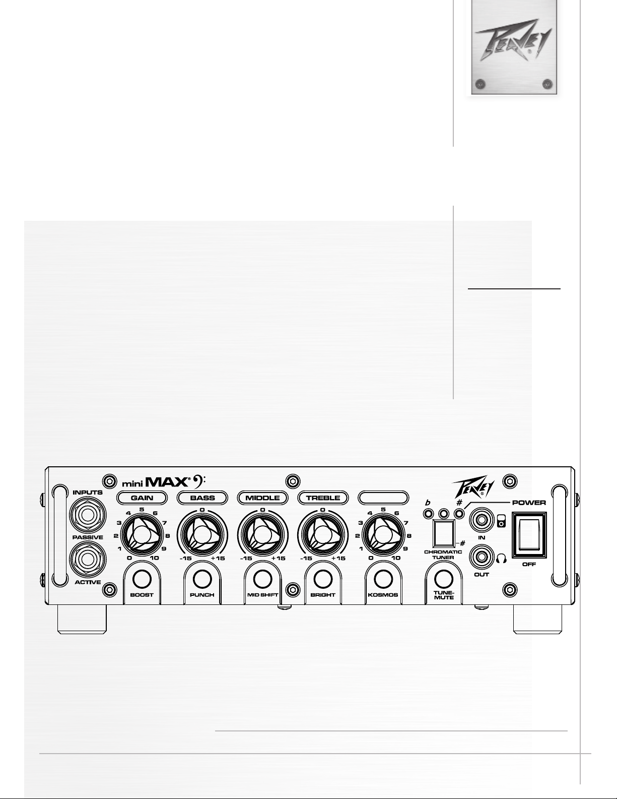
Front Panel
1 2 4 6 8 10 13
VOLUME
1 3 5 7 9 11 12 14 15
ACTIVE/PASSIVE PICKUP Inputs
1
These 1/4" inputs are included so you can choose the appropriate setting for your instrument. The gain structure of the
amplier is modied to accommodate the outputs of dierent pickup congurations.
GAIN
2
This knob controls input level of the instrument.
3
TT BOOST SWITCH
This TransTube® crunch circuit is designed so that the volume of the amp will not change when the boost is switched
on, but the distortion level will increase depending on the level of the GAIN knob. For best results, rst set the distortion
amount by adjusting the GAIN. Next, set the desired volume using the VOLUME knob. At this point, the clean volume will
match if the TT BOOST is turned o.
BASS
4
This knob provides a shelving tone control for low frequencies and provides cut/boost of +/-15 dB. The center point is
at. The center frequency is 50 Hz. -3 dB shelf corner frequency is 100Hz.
5
PUNCH
This switch engages a boost of 6dB at 100Hz, which greatly enhances the low-end presence of the bass guitar.
6
MIDDLE
This knob provides a peaking tone control for Mid frequencies and cut/boost of +/-15dB. The center point is at.
MID SHIFT
7
This switch controls the center frequency of the MIDDLE knob. When the switch is OUT, the middle frequency is 600Hz.
The middle frequency is 250Hz when the switch is pushed IN.
TREBLE
8
This knob provides a shelving tone control for high frequencies and cut/boost of +/-15dB. The center point is at and the
frequency is 8 KHz. -3dB; the shelf corner frequency is 5 KHz.
9
BRIGHT SWITCH
This button provides a 10 dB boost to frequencies above 1KHz. To activate, depress the switch to its “IN” position.
VOLUME
10
This knob controls the overall volume of the amplier.
11
Kosmos SWITCH
The human ear does not hear low frequencies as well as higher frequencies. This means that as bass goes lower, more
and more power is required. The MAX® Psycho-Acoustics eect solves this problem by identifying extremely low notes,
generating harmonics based on the notes, and then blending the harmonics with the original note, making the lows seem
louder and tighter without eating up excess power amp headroom.

12
TUNE/MUTE
Pressing this button will engage the chromatic tuner while muting the output to the speaker. The LED screen will indicate
which note is being played while the red and green LEDs above the screen indicate whether the note is at (red), sharp
(red) or in tune (green). This switch also mutes the DI.
AUX INPUT
13
This 1/8" input jack allows you to connect a CD player or MP3 player to your MAX Series bass amp
and play along
HEADPHONE OUTPUT
14
1/8" headphone output for personal monitoring.
15
POWER SWITCH
This switch is used to turn the amp on and o.
CAUTION: The on/o switch in this unit does not break both sides of the primary mains. Hazardous energy can be present
inside the chassis even when the on/o switch is in the OFF position.
Rear Panel
PRE /
GND /
LIFT
21 2220
DI
DESIGNED AND
ENGINEERED IN U.S.A.
MADE IN CHINA
23
16 18
Consumo de energia 160Wh
50/60 Hz
160 WATTS
FUSE
220-240V
120V
16
AC POWER INLET
T3.15AL/250V
T5AL/250V
17
220-240V
120V
FOR 220-240V
OPERATION,
FUSE MUST BE
CHANGED TO
T3.15AL/250V
FOR 120V
OPERATION,
FUSE MUST BE
CHANGED TO
T5AL/250V
Serial Sticker
SPE AKER OUTS
4 MIN LOAD
44.7V RMS
CLASS 2 WIRING
SPEAKER JACKS
PARALLELED
FX LOOP
POST
SEND
RETURN
This is the receptacle for an IEC line cord, which provides AC power to the unit. Connect the line cord to this connector to
provide power to the unit. Damage to the equipment may result if improper line voltage is used. (See line voltage marking
on unit).
Never break o the ground pin on any equipment. It is provided for your safety. If the outlet used does not have a ground
pin, a suitable grounding adapter should be used, and the third wire should be grounded properly. To prevent the risk of
shock or re hazard, always make sure that the amplier and all associated equipment is properly grounded.
NOTE: FOR UK ONLY
As the colors of the wires in the mains lead of this apparatus may not correspond with the colored markings identifying
the terminals in your plug, proceed as follows: (1) The wire that is colored green and yellow must be connected to the
terminal that is marked by the letter E, or by the Earth symbol, or colored green or green and yellow. (2) The wire that is
colored blue must be connected to the terminal that is marked with the letter N, or the color black. (3) The wire that is
colored brown must be connected to the terminal that is marked with the letter L, or the color red.
17
FUSE
The fuse is located within the cap of the fuse holder. If the fuse should fail, IT MUST BE REPLACED WITH THE SAME TYPE
AND VALUE IN ORDER TO AVOID DAMAGE TO THE EQUIPMENT AND TO PREVENT VOIDING THE WARRANTY. If the amp
repeatedly blows fuses, it should be taken to a factory authorized service center for repair.
WARNING! NEVER ATTEMPT TO REMOVE THE FUSE CAP OR REPLACE THE FUSE UNLESS THE POWER CORD HAS BEEN
DISCONNECTED FROM THE POWER OUTLET.

18
LINE VOLTAGE SELECT SWITCH
This selector switch allows the amplier to be operated at dierent line voltages. Please be sure this switch is set to the
proper voltage for your area before connecting the amplier to a power source or turning the amplier on for the rst time.
NEVER CHANGE THE POSITION OF THIS SWITCH WHILE THE AMPLIFIER IS TURNED ON.
CAUTION! THE FUSE MUST BE CHANGED TO THE CORRECT VALUE PRINTED ON THE REAR OF THE CHASSIS IF
A DIFFERENT LINE VOLTAGE IS SELECTED.
SPEAKER OUTPUT JACKS
19
These combination 1/4" / twist-lock connectors are used to connect speaker cables to the amplier. The minimum load
impedance on the amplier is 4Ω, which means that either a single 4Ω cabinet, or two 8Ω cabinets may be used.
20
FX LOOP
The eects loop consists of the SEND and RETURN jacks, which are used to patch external eects processors post EQ
in the signal chain. Connect the SEND jack to the input of eects processors. Connect the RETURN jack to the output of
eects processors.
21
DI PRE/POST SELECT SWITCH
This switch is used to select the DI signal source from either pre or post EQ. Usually, if the DI is used in a live setting to
send signal to a PA system, it’s best to use the PRE EQ setting because the DI signal will not be eected by changing any
of the amplier controls, which allows independent EQ adjustments for the PA system. The POST EQ setting is useful for
recording, connecting the amplier to an external power amplier, or for live use if you run eects processors through the
FX LOOP.
22
XLR BALANCED DI OUTPUT
This XLR output is used to connect the Mini Max pre amp section to external equipment, such as mixing consoles, external
power ampliers, or recording equipment.
DI GND LIFT SWITCH
23
This switch may be used to eliminate hum caused by ground loops between the amplier and other equipment, such as a
mixing console.

Mini MAX® AMPLIFIER SPECIFICATIONS
POWER CONSUMPTION:
(1/8 rated power, 1KHz sine wave)
120vac/60Hz, 230vac/50Hz
160 Watts
POWER AMPLIFIER:
(Rated Power < 1% THD, 1KHz sine wave, nominal line)
600 Watts continuous into 4 ohms (minimum load)
350 Watts continuous into 8 ohms
PRE-AMPLIFIER:
Maximum Input Sensitivity:
(PRE GAIN = 10, LOW/MID/HIGH = 5, VOLUME = 10, all voicing switches defeated)
Passive Input 40mV / -25.74dBu
Active Input 110mV / -16.95dBu
Auxiliary Input 1.0V / 2.22dBu
Nominal Input Sensitivity:
(PRE GAIN = 5, LOW/MID/HIGH = 5, VOLUME = 5, all voicing switches defeated)
Passive Input 500mV / -3.80dBu
Active Input 1.40mV / -16.95dBu
Auxiliary Input 1.0V / 2.22dBu
Headphone Output:
(Mono signal split to stereo)
50mW x 2 into 8-ohm minimum load
Noise Floor = -80dB

Logo referenced in Directive 2002/96/EC Annex IV
The bar is the symbol for marking of new waste and
13 August 2005
Warranty registration and information for U.S. customers available online at
Peavey Electronics Corporation 5022 Hartley Peavey Drive Meridian, MS 39305 (601) 483-5365 FAX (601) 486-1278
www.peavey.com
www.peavey.com/warranty
or use the QR tag below
Features and specications subject to change without notice.
(OJ(L)37/38,13.02.03 and defined in EN 50419: 2005
is applied only to equipment manufactured after
 Loading...