

Page 1
Invective™ 120
Amplier Head
Operating
Manual
www.peavey.com
1
Page 2

FCC/ICES Compliancy Statement
This device complies with Part 15 of the FCC rules and Industry Canada license-exempt RSS Standard(s). Operation is
subject to the following two conditions: (1) this device may not cause harmful interference, and (2) this device must
accept any interference received, that may cause undesired operation.
Le présent appareil est conforme aux CNR d’lndustrie Canada applicables aux appareils radio exempts de
licence. L’exploitation est autorisée aux deux conditions suivantes: (1) I’appareil ne doit pas produire de
brouillage, et (2) I’utilisateur de I’appareil doit accepter tout brouillage radioélectrique subi, même si le
brouillage est susceptible d’en compromettre le fonctionnement.
Warning: Changes or modifications to the equipment not approved by Peavey Electronics Corp. can void the
user’s authority to use the equipment.
Note – This equipment has been tested and found to comply with the limits for a Class B digital device,
pursuant to Part 15 of the FCC Rules. These limits are designed to provide reasonable protection against
harmful interference in a residential installation. This equipment generates, uses, and can radiate radio
frequency energy and, if not installed and used in accordance with the instructions, may cause harmful
interference to radio communications. However, there is no guarantee that interference will not occur in a
particular installation. If this equipment does cause harmful interference to radio or television reception,
which can be determined by turning the equipment off and on, the user is encouraged to try and correct the
interference by one or more of the following measures.
• Reorient or relocate the receiving antenna.
• Increase the separation between the equipment and receiver.
• Connect the equipment into an outlet on a circuit different from that to which the receiver is
connected.
• Consult the dealer or an experienced radio/TV technician for help.
Caution
The equipment complies with FCC radiation exposure limits set forth for an uncontrolled
environment.
2
Page 3

ENGLISH
e new sound of metal is here. e Invective™ 120 is the culmination of nearly three decades of renements
and tweaks to Peavey’s legendary 6505 series with an all new clean channel and gobs of peripheral features that
are staples for today’s developing musical styles. Designed in close conjunction with Misha Mansoor, of Periphery fame, the result is a monster of an amplier capable of accurately reproducing tons and tons of the sickest
tube amp tones imaginable….past, present, and future. ree separate channels (Clean/Crunch/Lead) and
two independent input boosts (one for clean, one for high gain channels) give you a sonic palette that lets your
imagination run wild. ere’s also a defeatable gate at the input of both gain channels designed to quickly mute
the input for a more “precise” muting characteristic. Capable of 120 Watts of earth shaking power, into the allnew solid pine Invective 212 (or any standard guitar cabinet), this behemoth can blow the roof o the largest
of venues or….with a twist of the Master Volume and a ip of the half power switch, keep a crowd in the smallest of clubs. Further tonal mayhem can be accomplished with outboard eects via the footswitchable Eects
Loops. e included 10-button MIDI footswitch allows for switching of all peripheral functions and storage of
presets. We’ve also included an internal MSDI direct analog recording/mic’d output and two auxiliary 9VDC
supply jacks for quick evaluation of pedals or to power a wireless setup. e all new Peavey® Invective™ 120….a
more than worthy successor to the legacy of Peavey’s high gain supremacy.
Features
• ree channels
• Preamp gain boost with gain and tone controls on Clean
• Preamp boost with level and tone controls on high gain channels
• Input gate on high gain channels
• Master Volume and Master Boost
• Resonance and Presence power amp damping controls
• MSDI direct out with level and tone controls
• Two Switchable eects loops
• Footswitch/MIDI In and MIDI Out jack
• Auxiliary 9VDC supplies
• 120W (rms) into 4, 8, or 16 Ohms (selectable impedance)
• Half power switch
• 10-button footswitch included
• Full set of current-based bias test points for easy troubleshooting
3
Page 4
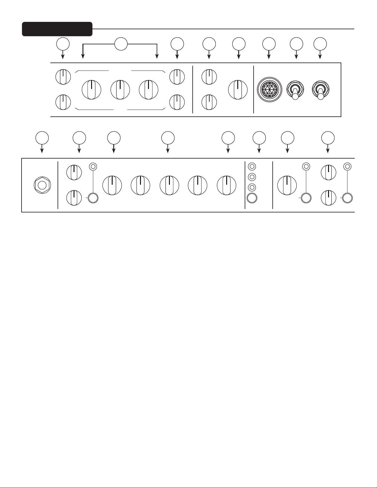
FRONT PANEL
RESONANCE
LOW MID VOLUMEHIGH
PRE GAIN POST GAIN
0 10
1 9
2 8
3 7
456
0 10
1 9
2 8
3 7
456
0 10
1 9
2 8
3 7
4
5
INPUT
456
3 7
2 8
1 9
0 10
PRE GAIN POST GAIN
456
3 7
2 8
1 9
0 10
3 7
2 8
1 9
3 7
2 8
DRIVE TONE
1 9
456
0 10
456
0 10
456
3 7
2 8
1 9
0 10
LOW MID VOLUMEHIGH
ENABLE
ENABLE ENABLE
CRUNCH
456
3 7
2 8
1 9
0 10
2 8
LEAD
3 7
2 8
1 9
BOOST
456
0 10
456
3 7
2 8
1 9
0 10
PRE LOW MID
456
3 7
1 9
0 10
3 7
2 8
1 9
3 7
2 8
1 9
CLEAN GATE
456
3 7
2 8
1 9
0 10
456
0 10
456
0 10
456
3 7
2 8
1 9
PRESENCE
0 10
456
3 7
2 8
1 9
0 10
456
3 7
2 8
1 9
0 10
HIGH
MASTER
456
3 7
2 8
1 9
0 10
456
3 7
2 8
1 9
0 10
POST
CLN
CRCH
LEAD
SEL
CHANNEL
234568 7
10111213141516
456
3 7
2 8
1 9
0 10
THRESHOLD
ENABLE
1
ONON
POWERSTANDBY
9
456
3 7
2 8
1 9
0 10
456
3 7
2 8
LEVEL TONE
1 9
0 10
BOOST
(1) POWER SWITCH
Applies mains power to the unit. e red POWER STATUS LAMP (3) will illuminate when this switch is in the
ON position.
(2) STANDBY SWITCH
Engages the high voltage tube supply for immediate operation aer warm up.
TIP: Always allow for at least 5 minutes of warm up time before engaging the Standby switch. is will improve
performance and reliability of the power tubes.
(3) POWER STATUS LAMP
Illuminates when mains power is being supplied to the amp.
(4) MASTER VOLUME
Sets the overall volume level of the amp. Once the desired balance between the three channels in the amplier
has been achieved, the entire output level of the unit can be increased or decreased by rotating this control.
Note: this control is aer the eects loops in the signal path
(5) RESONANCE & PRESENCE
Allows for adjustment of the damping factor of the power amplier. Damping is the ability of an amplier to
control speaker cone motion aer the signal disappears. A higher damping factor reduces cone vibration more
quickly than a lower damping factor in the aected frequency range. e actual damping factor of the amplier
decreases as the knobs are turned up. Resonance works on the low end and Presence exclusively aects the high
end response of the power amp.
4
Page 5

(6) POST GAIN
is control, on the CRUNCH and LEAD channels, sets the overall level of its respective channel.
(7) LOW, MID, and HIGH EQ
ese passive controls, on both the Crunch and Lead channels, provide the signature tone print of the Invective
120.
(8) PRE GAIN
is control, on both the Crunch and Lead channels, controls the input volume level/gain of its respective channel. is control will increase the amount of preamp distortion and sustain.
(9) BOOST SECTION
is group of controls dictates the sound of the switchable BOOST section of the CRUNCH and LEAD channels. is is an input volume boost which pushes the high gain section of the amp to work against the gate for
maximum edge.
(10) GATE THRESHOLD
Turning up this switchable control, on both the CRUNCH and LEAD channels, controls the level at which the
input gate triggers to mute the incoming signal.
(11) CHANNEL
is momentary switch allows selection between the three channels. CHANNEL ACTIVATION LEDs indicate
which channel is active. Channel switching can also be accomplished from the included footswitch.
(12) VOLUME
is control, on the CLEAN channel, sets the overall level going to the power amp.
(13) LOW, MID, and HIGH EQ
ese passive controls provide the desired EQ curve for this channel.
(14) PRE
is knob controls the input sensitivity of this channel.
(15) BOOST SECTION
is group of controls dictates the sound of the switchable BOOST section of the CLEAN channel. is is an
input gain boost which pushes the clean section of the amp into classic overdrive territory.
(16) INPUT
is ¼” jack is designed to accommodate signals from any electric guitar, with active or passive pickups.
5
Page 6

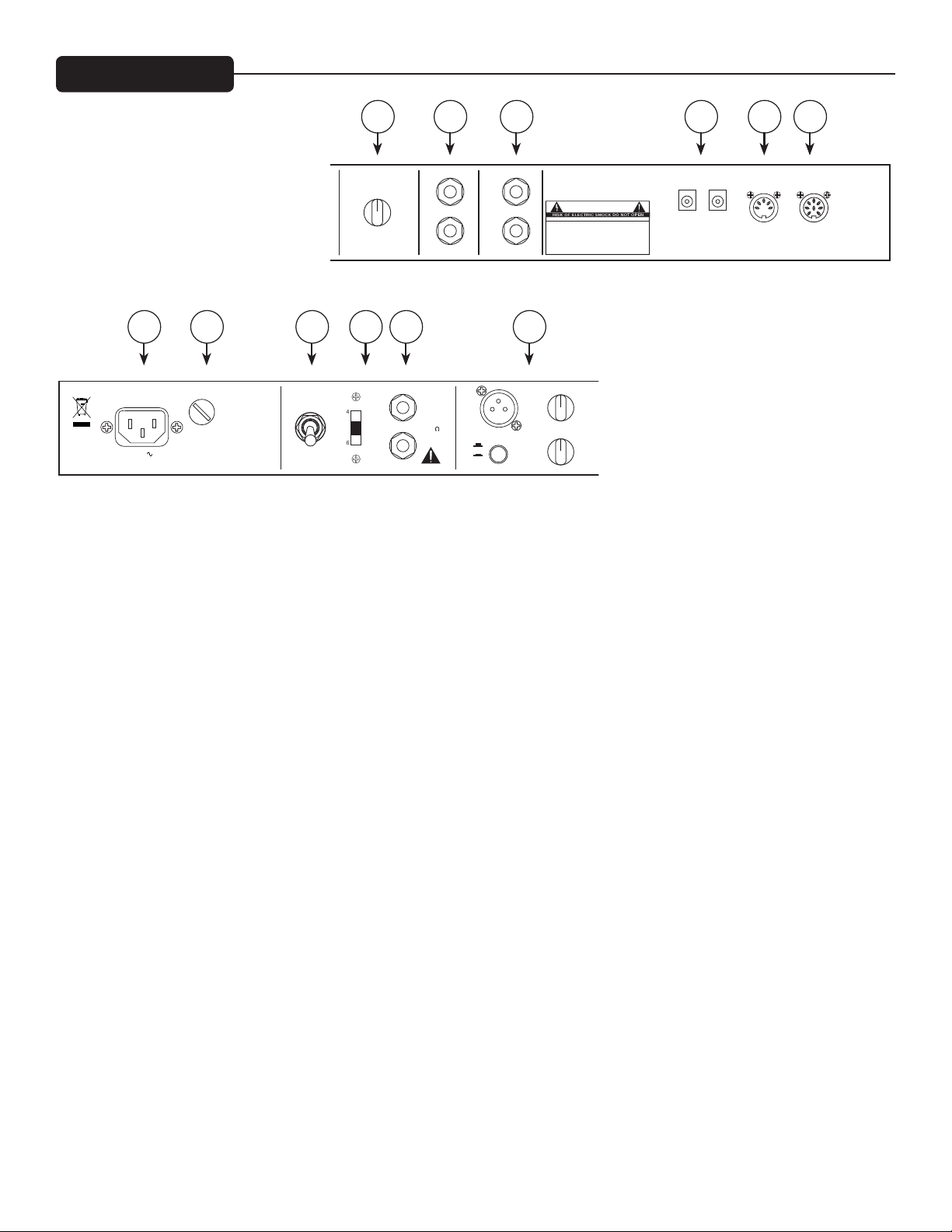
REAR PANEL
MASTER BOOST
EFFECTS LOOP 1
EFFECTS LOOP 2
POWER
SUPPLY
MSDI
MASTER BOOST
(NEGATIVE TIP)
RETURN
SEND
RETURN
MICROPHONE SIMULATED
LEVEL
LEVEL
SPEAKER OUTPUTS
CAUTION
WARNING:
APPARATUS SHOULD NOT BE EXPOSED TO RAIN OR MOISTURE AND
HAZARD, REPLACE WITH SAME TYPE 250 VOLT FUSE.
TO REDUCE THE RISK OF FIRE OR ELECTRIC SHOCK, THIS
DANS LE BUT DE REDUIRE LES RISQUES D’INCENDIE OU DE
AVIS:
A LA PLUIE OU A L’HUMIDITE ET AUCUN OBJET REMPLI DE LIQUIDE,
DECHARGE ELECTRIQUE, CET APPAREIL NE DOIT PAS ETRE EXPOSE
TEL QU’UN VASE, NE DOIT ETRE POSE SUR CELUI-CI. REMPLACER
PAR UN FUSIBLE DE MEME TYPE ET DE 250 VOLTS.
AVIS:
RISQUE DE CHOC ELECTRIQUE NE PAS OUVRIR
OBJECTS FILLED WITH LIQUIDS, SUCH AS VASES, SHOULD NOT
BE PLACED ON THIS APPARATUS. TO PREVENT THE RISK OF FIRE
SEND
A PRODUCT OF PEAVEY
ELECTRONICS CORP.
www.peavey.com
9VDC @ 500mA
EFFECTS LOOP 1
EFFECTS LOOP 2
0 10
1 9
2 8
3 7
456
171819202122
456
3 7
2 8
1 9
0 10
LEVEL
RETURN
SEND
RETURN
WARNING:
APPARATUS SHOULD NOT BE EXPOSED TO RAIN OR MOISTURE AND
OBJECTS FILLED WITH LIQUIDS, SUCH AS VASES, SHOULD NOT
BE PLACED ON THIS APPARATUS. TO PREVENT THE RISK OF FIRE
AVIS:
DECHARGE ELECTRIQUE, CET APPAREIL NE DOIT PAS ETRE EXPOSE
A LA PLUIE OU A L’HUMIDITE ET AUCUN OBJET REMPLI DE LIQUIDE,
TEL QU’UN VASE, NE DOIT ETRE POSE SUR CELUI-CI. REMPLACER
SEND
CAUTION
RISQUE DE CHOC ELECTRIQUE NE PAS OUVRIR
AVIS:
TO REDUCE THE RISK OF FIRE OR ELECTRIC SHOCK, THIS
HAZARD, REPLACE WITH SAME TYPE 250 VOLT FUSE.
DANS LE BUT DE REDUIRE LES RISQUES D’INCENDIE OU DE
PAR UN FUSIBLE DE MEME TYPE ET DE 250 VOLTS.
A PRODUCT OF PEAVEY
ELECTRONICS CORP.
www.peavey.com
9VDC @ 500mA
(NEGATIVE TIP)
POWER
SUPPLY
DESIGNED AND
ENGINEERED IN USA
MIDI MIDI
OUT/
THRU
FOOT-
SWITCH IN
232425262728
CAN-ICES-3(B)/NMB-3(B)
Consumo de energia 300Wh
Consumo de energia
en modo de espera 92Wh
120V
60 Hz
300 WATTS
FUSE
F5AL/250V
FULL POWER
HALF POWER
OUTPUT
POWER
SPEAKER JACKS PARALLELED
FULL
HALF
4168
8 16
32
IMPEDANCE
120W RMS/
44V RMS 4 MIN.
CLASS 2 WIRING
DIRECT INTERFACE
GROUND
LIFT
OUTPUT
456
3 7
2 8
TONE
1 9
0 10
456
3 7
2 8
1 9
0 10
(17) MIDI IN/FOOTSWITCH
is 8-pin DIN connector is provided for the connection of the remote footcontroller. See the FOOTSWITCH
section of this manual for a more detailed explanation of operation. is can also be used as a MIDI IN connection, using a standard 5-pin MIDI cable, if the amp is going to be controlled by a separate MIDI controller other
than the supplied footcontroller. See the MIDI section of this manual for a more detailed explanation of the
MIDI features.
(18) MIDI OUT
is 5-pin DIN connector is provided to send MIDI messages, including Program Change and Continuous Controller messages, to external MIDI devices. It is useful for linking two amps and keeping their functions synchronized, and for sending your custom preset data to another amp or MIDI backup device. It’s also useful to control
presets on eects units you may have in the eects loops. See the MIDI section of this manual for a more detailed
explanation of the MIDI features.
(19) 9VDC AUX POWER SUPPLY
ese pedal-standard, 9VDC (negative tip) barrel jacks are provided for quick power connection to a variety of
pedals or other peripheral devices. Each jack is capable of providing up to 500mA of current.
(20 and 21) EFFECTS LOOPS
ese series loops are used to route the Invective 120 signal path through external eects devices or signal processors.
Note: the loops are aer the master boost, but before the master volume in the signal path. is allows the master
boost to not boost/cut ambient eects trails.
(22) MASTER BOOST
is control sets the amount of footswitchable post-EQ volume boost available with a range of 0-5dBV.
Note: this control is before the eects loops in the signal path.
6
Page 7

(23) MSDI SECTION
e proprietary Peavey MSDI circuit provides a balanced microphone-simulated direct signal to outboard
recording gear and mixers. e “microphone” compensation very accurately reproduces the sound of whatever
cab you are using in conjunction with the Invective 120. e LEVEL control adjusts the output level of the XLR
jack, the TONE control adjusts the extreme high frequency response of the output to accommodate dierent
high frequency drivers in PA systems, and the GROUND LIFT switch is used to break hum-inducing ground
loops between the Invective 120 and outboard equipment.
(24) SPEAKER OUTPUTS
Paralleled ¼” mono (TS) jacks are provided for the connection of speaker enclosure(s). e Impedance switch
should be set to match the load of the speaker cabinet(s), as described above. Always use good quality speaker
cables (not shielded instrument cable) for these connections.
(25) IMPEDANCE SELECTOR
ree-position switch allows for appropriate selection of speaker cabinet impedance. If two enclosures of equal
impedance are used, the switch should be set to half the individual value. For example, two 16 Ohm enclosures
necessitate an 8 Ohm setting, while two 8 Ohm enclosures would require a 4 Ohm setting. When using the amp
in HALF POWER mode, note that there is a 2:1 impedance dierence which is also listed near the switch.
(26) OUTPUT POWER
is switch sets the maximum power level to either Full or Half, is literally shuts o two of the four power
output tubes.
(27) AC MAINS FUSE
is fuse is for the mains supply for the amp. e fuse is located within the cap of the fuse holder. is fuse must
be replaced with one of the same type and value to avoid damaging the amplier and voiding the warranty. If the
amp repeatedly blows the fuse, it should be taken to a qualied service center for repair.
WARNING: THE FUSE SHOULD ONLY BE REPLACED AFTER THE POWER CORD HAS BEEN DISCONNECTED.
(28) IEC MAINS CONNECTOR
is is a standard IEC power connector. An AC mains cord having the appropriate AC plug and ratings for the
intended operating voltage is included in the carton. e mains cord should be connected to the amplier before
connecting to a suitable AC outlet.
U.S. DOMESTIC AC MAINS CORD
e mains cord supplied with the unit is a heavy-duty, 3-conductor type with a conventional 120 VAC plug
with ground pin. If the outlet used does not have a ground pin, a suitable grounding adapter should be
used, and the third wire should be grounded properly.
Never break o the ground pin on any equipment. It is provided for your safety.
NOTE: FOR U.K. ONLY
If the colors of the wires in the mains lead of this unit do not correspond with the colored markings identifying the terminals in your plug, proceed as follows: (1) e wire that is colored green and yellow must be
connected to the terminal that is marked by the letter E, the earth symbol, colored green, or colored green
and yellow. (2) e wire that is colored blue must be connected to the terminal that is marked with the letter
N or the color black. (3) e wire that is colored brown must be connected to the terminal that is marked
with the letter L or colored red.
7
Page 8

TOP PANEL
V5 V2 V1 V6
29
30
V9
V10
V7V8
V3V4
12AX7A/ECC83 x 6
Preamp tubes. Tubes function as follows:
V1 = Crunch/Lead stages 1/2
V2 = Crunch/Lead stages 3/4
V3 = Loop driver/PI driver
V4 = Phase Inverter
V5 = Crunch/Lead stages 5/6
V6 = Clean channel
6L6GC x 4
Power tubes. Apart from 6L6GC, other types can be used including EL34, 6550, KT66, KT88 and 6CA7. When
replacing please use matched quartets of good quality tubes and ensure the biasing is set correctly as described
below. V7 and V9 are switched out of circuit in half power mode.
Please Note: Due to the high temperatures, do not attempt to replace any tubes unless the amplier has been
turned o for at least 15 minutes. is should only be carried out by a technically competent person.
(29) BIAS ADJUST
Adjusting this will vary the bias supply. is should only be adjusted by a qualied Peavey technician, otherwise
it could damage your tone, or worse, damage your power tubes.
(30) BIAS TEST POINTS
ese voltage test points are provided for technicians to use for quickly determining the plate current of each
power tube. Using a DC millivolt (mV) meter, one can measure voltage from the BIAS COMMON to the red
test point for a given tube. e resulting reading in mV is directly proportional to the plate current of that tube
(i.e.: 35mVDC = 35mA plate current). Optimum idle plate current for stock tubes is 26mA per tube.
WARNING: Removing the rear panel will expose the tubes. ese are VERY hot and touching them should be
avoided. is procedure should only be carried out by technically competent people and at their own risk.
8
Page 9

FOOTSWITCH
32 33 34 35 36
31
37 38 39 40 41
(31) Remote Cable
An eight-pin DIN connector is provided for connecting the footcontroller to the amplier IN/FOOT (38) via the
cable included in the carton.
(32) Preset Mode
Switches the footcontroller between NORMAL mode (default, LED o) and PRESET mode (LED red). Other
LEDs will be red for Preset Mode, and green for Normal Mode. (See “Using Preset Mode” section on pg. 10)
(33) Eects Loop 1 / Preset # 1
NORMAL mode: is turns on Eects Loop 1.
PRESET mode: is selects Preset 1. If selected, the LED will be lit red.
(34) Eects Loop 2 / Preset # 2
NORMAL mode: is turns on Eects Loop 2.
PRESET mode: is selects Preset 2. If selected, the LED will be red.
(35) Gate / Preset # 3
NORMAL mode: is turns on the gate circuit when using Channel 2 or 3.
PRESET mode: is selects Preset 3. If selected, the LED will be red.
(36) MIDI CC4 / Preset #4
NORMAL mode: is will send MIDI controller 4 with data 0 (LED o) or 127 (LED on) to control external
MIDI gear.
PRESET mode: is selects Preset 4. If selected, the LED will be red.
9
Page 10

(37) Drive Boost / Preset #5
NORMAL mode: is turns Drive BOOST on and o for the current channel. When switching between channels, this will remember what the last setting was for each. e LED will be green when Drive BOOST is on.
PRESET mode: is selects Preset 5. If selected, the LED will be red.
(38) Channel Select 1 / Preset #6
NORMAL mode: is selects Channel 1. e LED will be lit GREEN. If pressed a 2nd time, the channel will
return to the previous setting. is allows quick changing between two channels using a single switch.
PRESET mode: is selects Preset 6. If selected, the LED will be red.
(39) Channel Select 2 / Preset #7
NORMAL mode: is selects Channel 2. e LED will be lit GREEN. If pressed a 2nd time, the channel will
return to the previous setting. is allows quick changing between two channels using a single switch.
PRESET mode: is selects Preset 7. If selected, the LED will be red.
(40) Channel Select 3 / Preset #8
NORMAL mode: is selects Channel 3. e LED will be lit GREEN. If pressed a 2nd time, the channel will
return to the previous setting. is allows quick changing between two channels using a single switch.
PRESET mode: is selects Preset 8. If selected, the LED will be red.
(41) Master Boost / Preset #9
NORMAL mode: is turns the Master Boost on and o. e LED will be lit green.
PRESET mode: is selects Preset 9. If selected, the LED will be red.
USING PRESET MODE
Each of the 9 presets remembers the current channel, drive boost on/o, gate on/o, CC4 on/o, eects loop on/
o and master boost on/o. Additionally, it remembers the drive boost and gate status of the inactive channels.
is way you can, for example, have a clean preset saved without drive boost, and know that when you switch to
Channel 2, drive boost will be on.
e amp comes from the factory with 9 default presets that you can modify at will. When the PRESET MODE
light is on, you can use the 9 other footswitches to recall those 9 presets. At any time you can switch to NORMAL mode and make changes to that sound. is can be during a performance and not permanently stored, or
to edit a preset and store to one of the 9 settings.
STORING PRESETS
To store the current settings into one of the 9 presets, you start by holding the PRESET MODE switch down for
a second or two, aer which the other LEDs will blink (except the one for the current preset which will be on
steady – a way to remind you of which preset you were working with). At this point you can press one of the 9
preset switches to store there, or press PRESET MODE again to cancel.
10
Page 11

You can initiate this from PRESET mode or from NORMAL mode. Aer the store (or cancel) it will return to the
mode you were in. So you can setup and store 9 presets without ever entering PRESET mode if you wish. It’s
typical to set up your sound in NORMAL mode, then store your creation to one of the presets.
QUICK BOOST
As described below, when in preset mode, the 1-9 switches will recall your 9 custom presets. When you press the
switch of the preset that is already active, it will toggle the status of the Master Boost. is allows a quick way to
recall a preset for a solo and get it boosted very quickly (just hit the switch twice!). Otherwise, you’d have to hit it,
then toggle out of preset mode, then hit the Master Boost switch – tap dance! (Of course, you can save the preset
with the boost active, and then the 2nd press would disable the boost.) To make the Master Boost status visual
while in preset mode (red LEDs for mode/preset) the 9/Master Boost LED will blink green when the boost is enabled. (If on preset 9, the color will toggle between red and green to show preset number and Master Boost on).
LINKING TO ANOTHER AMP AND/OR EFFECTS UNITS WITH THE MIDI OUT
You can connect the MIDI Out to the MIDI In of another Invective 120 to synchronize the two amps. With the
footswitch connected to the rst amp, any changes you make with the footswitch (or front panel) will be duplicated on the 2nd amp – if the 2nd amp is on the same MIDI channel. See MIDI Program Section (pg. 13).
You can also link the MIDI from the amp (or from the 2nd amp) to an eects unit to synchronize presets. If the
eects unit can store presets, they can change automatically when you recall presets on the footswitch.
Whenever a preset is recalled, it sends that program change command, followed by the controller status of CC4
(0 or 127 based on the CC4 function) and the controller status of CC10 (0 or 127 based on the MASTER BOOST
function). is allows the MIDI eects unit to respond to those controllers to do things like turn a delay on/
o, etc. e other footswitches also send CC messages when pressed, but not at preset recall like the above two.
(MASTER BOOST sends CC9 AND CC10. CC9 to control another invective, CC10 synced at preset recall for
MIDI control of other devices.) See MIDI section for CC numbers generated by each function.
11
Page 12

MIDI IMPLEMENTATION
is amp is designed to be extremely functional with the included 10-button footswitch. e 8-pin footswitch
jack also works as a standard 5-pin MIDI input - to go along with the standard 5-pin MIDI output. ere are
times when the amp will be run with other types of MIDI foot controllers, a PC in the studio, or by an automated
rack rig - or linked to another Invective via MIDI. is is the information you need to mate this amp with other
MIDI devices.
NOTE: e MIDI Out will send data to another Invective (for function sync), to a PC (for 2-way communication during remote control or preset dump), or to an eects unit in the eects loop. is jack does not act like an
Out/ru. Data received at the MIDI In doesn’t result in data on the MIDI Out unless it was a valid message for
this amp.
MIDI CC: MIDI Continuous Controllers are used to change one function at a time. Aer selecting a preset
(see below), modications to that preset can be done with these messages. Making these changes on the amp or
footswitch generates these CC messages at the MIDI out.
Bn CC# data where n=chan-1 Data: any
(Decimal) (Hex)
1 01h Select chan 1
2 02h Select chan 2
3 03h Select chan 3
Data: 00h-3Fh Data: 40h-7Fh
4 04h * *
* Amp doesn’t respond to this, but it sends it based on preset/CC4 footswitch for controlling external MIDI gear.
5 05h Drive Boost 1 OFF Drive Boost 1 ON
6 06h Drive Boost 2 OFF Drive Boost 2 ON
7 07h Drive Boost 3 OFF Drive Boost 3 ON
8 08h Drive Boost OFF Drive Boost ON (active channel)
9 09h ** **
** Amp doesn’t respond to this, but it sends it based on preset/Master Boost footswitch for controlling external
MIDI gear.
10 0Ah Master Boost OFF Master Boost ON
11 0Bh FX Loop 1 OFF FX Loop 1 ON
12 0Ch FX Loop 2 OFF FX Loop 2 ON
13 0Dh Gate 2 OFF Gate 2 ON
14 0Eh Gate 3 OFF Gate 3 ON
15 0Fh Gate OFF Gate ON (active chan, 2 or 3)
Example: B0 0A 7F enables master boost (MIDI chan 1)
12
Page 13

MIDI PROGRAM
MIDI Program Changes are used to recall presets. Typically a preset will recongure all functions on the amp at
one time. (Programs 9-11 below are exceptions as they only aect the channel.)
NOTE: ese messages when recevied will be echoed to the MIDI Out jack for sync’ing with another Invective.
NOTE: e rst nine presets are your custom presets. ey recall whatever you store with the footswitch.
CHANNEL DRIVE BOOST MASTER BOOST CC 4 GATE FX LOOP 1 FX LOOP 2
Cn data where n=chan-1 (preset saves for (preset saves for
(Decimal) (Hex) ...all three channels) ...channels 2 & 3)
0 00h <----------------------------------------preset 1--------------------------------------------------------->
1 01h <----------------------------------------preset 2--------------------------------------------------------->
2 02h <----------------------------------------preset 3--------------------------------------------------------->
3 03h <----------------------------------------preset 4--------------------------------------------------------->
4 04h <----------------------------------------preset 5--------------------------------------------------------->
5 05h <----------------------------------------preset 6--------------------------------------------------------->
6 06h <----------------------------------------preset 7--------------------------------------------------------->
7 07h <----------------------------------------preset 8--------------------------------------------------------->
8 08h <----------------------------------------preset 9--------------------------------------------------------->
Example: C0 00 recalls rst preset (MIDI chan 1)
Channel only:
9 09h 1 no change no change no change no change no change no change
10 0Ah 2 no change no change no change no change no change no change
11 0Bh 3 no change no change no change no change no change no change
e Factory Map is basically a long list of xed presets with every combination of function. If automating a performance from a MIDI rig, any combination of these functions can be found in this binary-style table.
NOTE: Due to MIDI limitations, the CC4 function is only controlled by the custom presets, not by the Factory
Map. It will be unchanged, not cleared.
blank = OFF; X = ON; n/a = not applicable
Factory Map: CHANNEL DRIVE BOOST MASTER BOOST GATE FX LOOP 1 FX LOOP 2
(decimal) (hex)
12 0Ch 1 n/a
13 0Dh 2
14 0Eh 3
15 0Fh 1 X n/a
16 10h 2 X
17 11h 3 X
18 12h 1 X n/a
19 13h 2 X
20 14h 3 X
21 15h 1 X X n/a
22 16h 2 X X
23 17h 3 X X
24 18h 1 n/a
25 19h 2 X
13
Page 14

Factory Map: CHANNEL DRIVE BOOST MASTER BOOST GATE FX LOOP 1 FX LOOP 2
(decimal) (hex)
26 1Ah 3 X
27 1Bh 1 X n/a
28 1Ch 2 X X
29 1Dh 3 X
30 1Eh 1 X X n/a
31 1Fh 2 X X X
32 20h 3 X X X
33 21h 1 X X n/a
34 22h 2 X X X
35 23h 3 X X X
36 24h 1 n/a X
37 25h 2 X
38 26h 3 X
39 27h 1 X n/a X
40 28h 2 X X
41 29h 3 X X
42 2Ah 1 X n/a X
43 2Bh 2 X X
44 2Ch 3 X X
45 2Dh 1 X X n/a X
46 2Eh 2 X X X
47 2Fh 3 X X X
48 30h 1 n/a X
49 31h 2 X X
50 32h 3 X X
51 33h 1 X n/a X
52 34h 2 X X X
53 35h 3 X X X
54 36h 1 X n/a X
55 37h 2 X X X
56 38h 3 X X X
57 39h 1 X X n/a X
58 3Ah 2 X X X X
59 3Bh 3 X X X X
60 3Ch 1 n/a X
61 3Dh 2 X
62 3Eh 3 X
63 3Fh 1 X n/a X
64 40h 2 X X
65 41h 3 X X
66 42h 1 X n/a X
67 43h 2 X X
68 44h 3 X X
69 45h 1 X X n/a X
70 46h 2 X X X
71 47h 3 X X X
72 48h 1 n/a X
73 49h 2 X X
14
Page 15

Factory Map: CHANNEL DRIVE BOOST MASTER BOOST GATE FX LOOP 1 FX LOOP 2
(decimal) (hex)
74 4Ah 3 X X
75 4Bh 1 X n/a X
76 4Ch 2 X X X
77 4Dh 3 X X X
78 4Eh 1 X n/a X
79 4Fh 2 X X X
80 50h 3 X X X
81 51h 1 X X n/a X
82 52h 2 X X X X
83 53h 3 X X X X
84 54h 1 n/a X X
85 55h 2 X X
86 56h 3 X X
87 57h 1 X n/a X X
88 58h 2 X X X
89 59h 3 X X X
90 5Ah 1 X n/a X X
91 5Bh 2 X X X
92 5Ch 3 X X X
93 5Dh 1 X X n/a X X
94 5Eh 2 X X X X
95 5Fh 3 X X X X
96 60h 1 n/a X X
97 61h 2 X X X
98 62h 3 X X X
99 63h 1 X n/a X X
100 64h 2 X X X X
101 65h 3 X X X X
102 66h 1 X n/a X X
103 67h 2 X X X X
104 68h 3 X X X X
105 69h 1 X X n/a X X
106 6Ah 2 X X X X X
107 6Bh 3 X X X X X
15
Page 16

MIDI SYSEX
MIDI System Exclusive Commands are used to do all kinds of things that standard commands don’t handle.
e Invective uses Sysex for things like backing up or restoring the 9 user presets, or transferring them to a 2nd
amp.
NOTE: Except where noted below these messages when received will NOT be echoed to the MIDI Out jack.
BUT if the message does not have the matching MIDI channel of the rst amp, it WILL echo it in case the 2nd
amp matches.
9-preset dump
request: F0h 00h 00h 1Bh 16h MIDI chan - 1 00h F7h
(0-15) (no data)
When the amp receives this command, it will send a 9-preset dump message (see below) to the MIDI Out jack. If
connected to another Invective’s In jack (and that amp on same MIDI channel), the presets will be copied to that
amp. Connect the MIDI Out to a storage device to backup your 9 custom presets.
9-preset dump: F0h 00h 00h 1Bh 16h MIDI chan - 1 01h 36 nibbleized bytes F7h
(receive or send) (0-15) (presets 0-8)
When the amp receives this command, it will overwrite the 9 custom presets with the data in the command (9
presets x 4 nibbleized bytes) - and ECHO the dump in case there is a 2nd amp connected to the MIDI Out (and
on the same MIDI channel). e amp will SEND this data if it receives the dump request above. Additionally,
this dump can be initiated manually by holding the Channel 1 Drive button and pressing the Channel Select
button.
current setting
dump request: F0h 00h 00h 1Bh 16h MIDI chan - 1 04h F7h
(0-15) (no data)
When the amp receives this command, it will send a current setting dump message (below) to the MIDI Out
jack. e main purpose is for a PC editor to get the current audible setting to sync its display with the amp. is
setting could be dierent from any of the 9 presets if has been modied in Stomp mode and not stored yet.
current setting
dump: F0h 00h 00h 1Bh 16h MIDI chan - 1 05h 4 nibbleized bytes F7h
(0-15) (current audible setting)
e amp will send this message when requested, but will ignore it if received. e current setting can be set easily
with controller or program change messages, so this method is not supported as an input message.
preset store: F0h 00h 00h 1Bh 16h MIDI chan - 1 06h preset # - 1 F7h
(0-15) (0-8)
When the amp receives this command, it will save the current audible preset to one of the 9 custom presets. e
audible preset could be modied via MIDI CC commands. Once the preset is satisfactory, it can be saved to one
of the 9 custom locations with this command. at would be the method of remote control with a PC, or for creating an editor/librarian application. Message is echoed in case there is a 2nd amp on the same channel.
16
Page 17

PRESET FORMAT
NOTE: commands that send nibbleized preset data send HIGH byte/nibble, then LOW.
Preset Bit: 15 14 13 12 11 10 9 8 7 6 5 4 3 2 1 0
Denition: n/a gate gate eects loop 2, 1 n/a CTL 4 master boost 1 for chan 3 1 for chan 1 Overboost
1 = active 3 2 / CTL 9 0 for chan 1 or 2 0 for chan 2 or 3 ch. 3, 2, 1
(n/a if bit 3 active)
set MIDI channel default chan=1
via sysex: F0h 00h 00h 1Bh 16h don’t care 0Dh channel - 1 F7h
(<= 0x7F) (0-15)
via footswitch:
Hold the last footswitch (9/Master Boost) for 2 seconds to enter MIDI channel select mode. e LEDs on the 1-8
footswitches will blink. You can then choose MIDI channel 1-8 by pressing one of those. You can also press 9/
Master Boost again to cancel the operation.
Note: e amp will always respond to the footswitch, but the MIDI channel allows it to
selectively respond to standard MIDI messages from other devices.
17
Page 18

SPECIFICATIONS
Power Amplier Section:
Rated Power & Load:
120W(rms) into 16, 8, or 4 Ohms
Power @ Clipping:
(Typically @ 5% THD, 1kHz, 120VAC line)
130W(rms) into 16, 8, or 4 Ohms
(Bias must be reduced to measure)
Frequency Response:
+0, -3dB, 50Hz to 20kHz, @ 100W(rms) into 8 Ohms
Hum & Noise:
Greater than 78dB below rated power
Power Amp EQ:
Active Presence: +10dB @ 2kHz
Active Resonance: +10dB @ cabinet resonant frequency
Power Consumption:
400W 50/60Hz, 120VAC (Domestic)
Pre-amp Section:
e following specs are measured @ 1kHz with the controls preset as follows:
Low & High EQ @ 10
Mid EQ @ 0
Post Gains @ 10
Resonance & Presence @ 0dB
Nominal levels with Pre Gains @ 5
Minimum levels with Pre Gains @ 10
All Gain boosts OFF
Gate OFF
All loops ON
Master Boost ON
Preamp Input:
Impedance: Very High Z, 470K Ohms
LEAD CHANNEL:
Nominal Input Level: -80dBV, 0.1mV(rms)
Minimum Input Level: -92dBV, 0.025mV(rms)
CRUNCH CHANNEL:
Nominal Input Level: -50dBV, 3.0mV(rms)
Minimum Input Level: -66dBV, 1.4mV(rms)
Maximum Input Level: -16dBV, 45mV(rms)
CLEAN CHANNEL:
Nominal Input Level: -8.0dBV, 400mV(rms)
Minimum Input Level: -21dBV, 90mV(rms)
Maximum Input Level: 0.0dBV, 1.0V(rms)
Eects Send:
Load Impedance: 1k Ohms or greater
Nominal Output: -10dBV, 300mV(rms)
18
Page 19

Eects Return:
Impedance: Very High Z, 470K Ohms
Designed Level: -10dBV, 300mV(rms)
System Hum & Noise @ Nominal Level:
(Clean Channel; 20Hz to 20kHz unweighted)
Greater than 78dB below rated power
Equalization:
Custom Low, Mid & High passive type EQ
Auxiliary Power Supply Jacks (x2):
9V DC (negative tip) @ 500mA
Dimensions: 26.7” W x 11.8” D x 10.0” H (678mm W x 300mm D x 254mm H)
Weight: 48.3lbs (21.9kg)
NOTE: Specications are subject to change without notice.
19
Page 20

Invective™ 120
Tête d'amplicateur
Mode
d’emploi
www.peavey.com
1
Page 21

FRANÇAIS
Voici le nouveau son du métal L’Invective™ 120 est l’aboutissement de près de trois décennies de réglages et
de rectications de la légendaire série 6505 de Peavey avec de tous nouveaux canaux clean et des fonctionnalités périphériques à foison qui sont la base pour les styles musicaux qui se développent d’aujourd’hui. Conçu
en étroite collaboration avec Misha Mansour, du célèbre Périphéry, le résultat est un monstre d’amplicateur
capable de reproduire avec précision des tonnes de tonalités d’amplis de tubes les plus dingues imaginables ....
passés, présents et futurs. Trois canaux distincts (Clean/Crunch/Lead) et deux Boosts d'entrée indépendants
(un pour Clean, un pour les canaux à gain élevé) vous donnent une palette sonore qui vous permet de donner
libre cours à votre imagination. Il y a aussi une porte désactivable à l’entrée des deux canaux de gain conçue
pour couper rapidement l’entrée pour une caractéristique de sourdine plus « précise ». Puissance séismique de
120 watts, dans le tout nouveau Invective 212 en pin massif (ou tout caisson de guitare standard), ce monstre
peut faire sauter le toit des plus grandes salles ou .... en modiant le volume principal et en basculant l’interrup-
teur de réduction de puissance de moitié, entretenir une foule dans le plus petit des clubs. Un chaos tonal supplémentaire peut être accompli avec des eets extérieurs via les boucles d’eets de la pédale. La pédale MIDI à
10 boutons intégrée permet de commuter toutes les fonctions périphériques et la mémorisation des préréglages.
Nous avons également inclus une sortie de micro/enregistrement analogique directe MSDI et deux prises
d’alimentation auxiliaires 9VDC pour l’évaluation rapide des pédales ou pour alimenter une conguration sans
l. Le tout nouveau Invective™ 120 de Peavey® .... un successeur plus que digne à la suprématie de la conception
existante à gain élevé Peavey.
Caractéristiques
• Trois canaux
• Amplication de gain de préamplication avec commandes de gain et de tonalité sur Clean
• Amplication de préamplication avec commandes de tonalité sur canaux à gain élevé
• Porte d’entrée sur les canaux à gain élevé
• Volume Master et Boost Master
• Contrôles d’amortissement des amplicateurs de puissance Résonance et Présence
• Sortie directe MSDI avec commandes de niveau et de tonalité
• Deux boucles d’eets commutables
• Prise de sortie MIDI et d’entrée MIDI/pédalier
• Alimentations 9VDC auxiliaires
• 120 W (rms) en 4, 8 ou 16 ohms (impédance sélectionnable)
• Commutateur de réduction de puissance de moitié
• Pédalier à 10 boutons intégré
• Ensemble complet de points de test de polarisation basé sur le courant pour un dépannage facile
2
Page 22

PANNEAU AVANT
RESONANCE
LOW MID VOLUMEHIGH
PRE GAIN POST GAIN
0 10
1 9
2 8
3 7
456
0 10
1 9
2 8
3 7
456
0 10
1 9
2 8
3 7
4
5
INPUT
456
3 7
2 8
1 9
0 10
PRE GAIN POST GAIN
456
3 7
2 8
1 9
0 10
3 7
2 8
1 9
3 7
2 8
DRIVE TONE
1 9
456
0 10
456
0 10
456
3 7
2 8
1 9
0 10
LOW MID VOLUMEHIGH
ENABLE
ENABLE ENABLE
CRUNCH
456
3 7
2 8
1 9
0 10
2 8
LEAD
3 7
2 8
1 9
BOOST
456
0 10
456
3 7
2 8
1 9
0 10
PRE LOW MID
456
3 7
1 9
0 10
3 7
2 8
1 9
3 7
2 8
1 9
CLEAN GATE
456
3 7
2 8
1 9
0 10
456
0 10
456
0 10
456
3 7
2 8
1 9
PRESENCE
0 10
456
3 7
2 8
1 9
0 10
456
3 7
2 8
1 9
0 10
HIGH
MASTER
456
3 7
2 8
1 9
0 10
456
3 7
2 8
1 9
0 10
POST
CLN
CRCH
LEAD
SEL
CHANNEL
234568 7
10111213141516
456
3 7
2 8
1 9
0 10
THRESHOLD
ENABLE
1
ONON
POWERSTANDBY
9
456
3 7
2 8
1 9
0 10
456
3 7
2 8
LEVEL TONE
1 9
0 10
BOOST
(1) INTERRUPTEUR MARCHE/ARRÊT
Met l’unité sous tension. Le VOYANT D’ÉTAT D’ALIMENTATION rouge (3) s’allume lorsque ce commutateur
est sur la position ON.
(2) INTERRUPTEUR STANDBY
Enclenche l’alimentation du tube haute tension pour un fonctionnement immédiat après la phase de préchauffage.
CONSEIL : Laissez toujours au moins 5 minutes de temps de préchauage avant d’enclencher le commutateur de
mode Standby. Cela permettra d'améliorer les performances et la abilité des tubes de puissance.
(3) VOYANT D'ÉTAT D'ALIMENTATION
Il s’allume lorsque l’alimentation est fournie à l’ampli.
(4) MASTER VOLUME
Règle le niveau de volume général de l’ampli. Une fois que la balance désirée entre les trois canaux de l’amplicateur a été réglée, le niveau de sortie totale de l’appareil peut être augmenté ou diminué en tournant cette commande.
Remarque: cette commande se trouve après les boucles d’eets dans le chemin du signal
(5) RÉSONANCE & PRÉSENCE
Permet le réglage du facteur d’amortissement de l’amplicateur de puissance. L’amortissement est la capacité
d’un amplicateur à contrôler le mouvement conique du haut-parleur après la disparition du signal. Un facteur
d'amortissement plus élevé réduit la vibration conique plus rapidement qu'un facteur d'amortissement inférieur
dans la plage de fréquences aectée. Le facteur d’amortissement eectif de l’amplicateur diminue à mesure que
les boutons sont tournés vers le haut. La résonance fonctionne sur l'extrémité inférieure et la présence aecte
exclusivement la réponse d'extrémité supérieure de l'ampli de puissance.
3
Page 23

(6) POST-GAIN
Cette commande, sur les canaux CRUNCH et LEAD, règle le niveau global de son canal respectif.
(7) EG BASSES, MOYENNE ET AIGUS
Ces commandes passives, à la fois sur les canaux Crunch et Lead, fournissent l’empreinte de tonalité de signature
de l’Invective 120.
(8) PRÉ-GAIN
Cette commande, sur les canaux Crunch et Lead, règle le gain/niveau de volume d’entrée de son canal respectif.
Cette commande augmentera la quantité de distorsion et de sustain (durée de vibration) du préampli.
(9) SECTION BOOST
Ce groupe de commandes dicte le son de la section BOOST commutable des canaux CRUNCH et LEAD. C’est
un boost de volume d’entrée qui pousse la section de gain haut de l’ampli pour fonctionner contre la porte pour
un front maximum.
(10) SEUIL DE PORTE
Tournez vers le haut cette commande commutable, à la fois sur les canaux CRUNCH et LEAD, permet de
contrôler le niveau auquel la porte d’entrée se déclenche pour couper le signal entrant.
(11) CANAL
Ce commutateur momentané permet la sélection entre les trois canaux. Les LED D'ACTIVATION DE CANAL
indiquent quel canal est actif. La commutation de canaux peut également être exécutée depuis la pédale intégrée.
(12) VOLUME
Cette commande, sur le canal CLEAN, règle le niveau global allant vers l’ampli de puissance.
(13) EG BASSES, MOYENNE ET AIGUS
Ces commandes passives fournissent la courbe d’égalisation souhaitée pour ce canal.
(14) PRÉ
Ce bouton contrôle la sensibilité d’entrée de ce canal.
(15) SECTION BOOST
Ce groupe de commandes dicte le son de la section BOOST commutable du canal CLEAN. C'est un boost de
gain d'entrée qui pousse la section Clean de l'ampli en mode overdrive classique.
(16) ENTRÉE
Cette prise ¼" est conçue pour recevoir les signaux d'une guitare électrique, avec des micros actifs ou passifs.
4
Page 24
PANNEAU ARRIÈRE
MASTER BOOST
EFFECTS LOOP 1
EFFECTS LOOP 2
POWER
SUPPLY
MSDI
MASTER BOOST
(NEGATIVE TIP)
RETURN
SEND
RETURN
MICROPHONE SIMULATED
LEVEL
LEVEL
SPEAKER OUTPUTS
CAUTION
WARNING:
APPARATUS SHOULD NOT BE EXPOSED TO RAIN OR MOISTURE AND
HAZARD, REPLACE WITH SAME TYPE 250 VOLT FUSE.
TO REDUCE THE RISK OF FIRE OR ELECTRIC SHOCK, THIS
DANS LE BUT DE REDUIRE LES RISQUES D’INCENDIE OU DE
AVIS:
A LA PLUIE OU A L’HUMIDITE ET AUCUN OBJET REMPLI DE LIQUIDE,
DECHARGE ELECTRIQUE, CET APPAREIL NE DOIT PAS ETRE EXPOSE
TEL QU’UN VASE, NE DOIT ETRE POSE SUR CELUI-CI. REMPLACER
PAR UN FUSIBLE DE MEME TYPE ET DE 250 VOLTS.
AVIS:
RISQUE DE CHOC ELECTRIQUE NE PAS OUVRIR
OBJECTS FILLED WITH LIQUIDS, SUCH AS VASES, SHOULD NOT
BE PLACED ON THIS APPARATUS. TO PREVENT THE RISK OF FIRE
SEND
A PRODUCT OF PEAVEY
ELECTRONICS CORP.
www.peavey.com
9VDC @ 500mA
EFFECTS LOOP 1
EFFECTS LOOP 2
0 10
1 9
2 8
3 7
456
171819202122
456
3 7
2 8
1 9
0 10
LEVEL
RETURN
SEND
RETURN
WARNING:
APPARATUS SHOULD NOT BE EXPOSED TO RAIN OR MOISTURE AND
OBJECTS FILLED WITH LIQUIDS, SUCH AS VASES, SHOULD NOT
BE PLACED ON THIS APPARATUS. TO PREVENT THE RISK OF FIRE
AVIS:
DECHARGE ELECTRIQUE, CET APPAREIL NE DOIT PAS ETRE EXPOSE
A LA PLUIE OU A L’HUMIDITE ET AUCUN OBJET REMPLI DE LIQUIDE,
TEL QU’UN VASE, NE DOIT ETRE POSE SUR CELUI-CI. REMPLACER
SEND
CAUTION
RISQUE DE CHOC ELECTRIQUE NE PAS OUVRIR
AVIS:
TO REDUCE THE RISK OF FIRE OR ELECTRIC SHOCK, THIS
HAZARD, REPLACE WITH SAME TYPE 250 VOLT FUSE.
DANS LE BUT DE REDUIRE LES RISQUES D’INCENDIE OU DE
PAR UN FUSIBLE DE MEME TYPE ET DE 250 VOLTS.
A PRODUCT OF PEAVEY
ELECTRONICS CORP.
www.peavey.com
9VDC @ 500mA
(NEGATIVE TIP)
POWER
SUPPLY
DESIGNED AND
ENGINEERED IN USA
MIDI MIDI
OUT/
THRU
FOOT-
SWITCH IN
232425262728
CAN-ICES-3(B)/NMB-3(B)
Consumo de energia 300Wh
Consumo de energia
en modo de espera 92Wh
120V
60 Hz
300 WATTS
FUSE
F5AL/250V
FULL POWER
HALF POWER
OUTPUT
POWER
SPEAKER JACKS PARALLELED
FULL
HALF
4168
8 16
32
IMPEDANCE
120W RMS/
44V RMS 4 MIN.
CLASS 2 WIRING
DIRECT INTERFACE
GROUND
LIFT
OUTPUT
456
3 7
2 8
TONE
1 9
0 10
456
3 7
2 8
1 9
0 10
(17) ENTREE MIDI/PÉDALE
Ce connecteur DIN à 8 broches est destiné à la connexion de la pédale de commande à distance. Voir la section
PEDALE de ce manuel pour une explication plus détaillée son fonctionnement. Il est également possible de l’utiliser en connexion MIDI IN en utilisant un câble MIDI standard à 5 broches, si l’amplicateur doit être contrôlé
par une commande MIDI spécique autre que la pédale. Voir la section MIDI de ce manuel pour une explication
plus détaillée des fonctions MIDI.
(18) SORTIE MIDI
Ce connecteur DIN à 5 broches est fourni pour envoyer des messages MIDI, y compris des messages de changement de programme et de contrôleur continu, aux périphériques MIDI externes. Il est utile pour relier deux amplis et maintenir leurs fonctions synchronisées, et pour envoyer vos données préréglées personnalisées à un autre
ampli ou périphérique de sauvegarde MIDI. Il est également utile pour contrôler les préréglages sur les systèmes
d’eets que vous pouvez avoir dans les boucles d’eets. Voir la section MIDI de ce manuel pour une explication
plus détaillée des fonctions MIDI.
(19) ALIMENTATION AUX 9VDC
Ces prises cylindriques 9VDC (embout négatif) sont fournies pour une connexion rapide à une variété de pédales ou d’autres périphériques. Chaque prise est capable de fournir jusqu’à 500 mA de courant.
(20 et 21) BOUCLES D’EFFETS
Ces boucles de série servent à acheminer le chemin du signal de l’Invective 120 par des systèmes d’eets externes
ou des processeurs de signaux.
Remarque : les boucles sont après le Master Boost, mais avant le Master Volume dans le chemin du signal. Cela
permet au Master Boost de ne pas amplier/couper les chemins d’eets ambiants.
(22) MASTER BOOST
Cette commande dénit la quantité de Boost de volume post-EG commutable par pédale disponible avec une
plage de 0 à 5 dBV.
Remarque: cette commande se trouve avant les boucles d’eets dans le chemin du signal.
5
Page 25

(23) SECTION MSDI
Le circuit MSDI exclusif de Peavey fournit un signal direct simulé par microphone à l’équipement d’enregistrement externe et aux mixeurs. La compensation « microphone » reproduit très précisément le son de tout cab que
vous utilisez en conjonction avec l’Invective 120. La commande de NIVEAU règle le niveau de sortie de la prise
XLR, la commande de TONALITÉ règle la réponse d’extrême haute fréquence de la sortie pour s’adapter aux différents conducteurs à haute fréquence dans les systèmes de sonorisation, et le commutateur GROUND LIFT sert
pour casser les boucles de terre induisant le ronement entre l’Invective 120 et l’équipement externe.
(24) SORTIE DE HAUT-PARLEUR
Des prises parallèles ¼” mono (TS) sont prévues pour la connexion des enceintes de haut-parleurs. Le sélecteur
d'impédance doit être réglé pour correspondre à la charge de la ou des enceintes de haut-parleurs, comme décrit
ci-dessus. Utilisez toujours des câbles de haut-parleur de bonne qualité (pas de câble d’instrument blindé) pour
ces connexions.
(25) SÉLECTEUR D’IMPÉDANCE
Ce bouton à trois positions permet de sélectionner l’impédance appropriée pour l’enceinte de haut-parleur. Si
deux enceintes d’impédance égale sont utilisées, l’interrupteur doit être réglé sur la moitié de la valeur individuelle. Par exemple, deux enceintes de 16Ω nécessitent un réglage de 8Ω, alors que deux enceintes de 8Ω nécessitent un réglage de 4Ω. Lorsque vous utilisez l'ampli en mode HALF POWER, notez qu'il y a une diérence
d'impédance de 2:1 qui est également indiquée près de l'interrupteur.
(26) PUISSANCE DE SORTIE
Ce commutateur règle le niveau de puissance maximum sur Full (100%) ou Half (50 %). Cela coupe littéralement
deux des quatre tubes de sortie de puissance.
(27) FUSIBLE SECTEUR AC
Ce fusible sert pour l’alimentation secteur de l’ampli. Le fusible se situe dans le bouchon du porte-fusible. Ce
fusible doit être remplacé par un fusible de type et de valeur identiques pour éviter d'endommager l'amplicateur
et annuler la garantie. Si le fusible de l’ampli saute plusieurs fois, il faut l’apporter à un centre d’entretien agréé
pour le faire réparer.
AVERTISSEMENT: LE FUSIBLE NE DOIT ÊTRE PLACÉ QUE LORSQUE LE CORDON D’ALIMENTATION A ÉTÉ DÉBRANCHÉ DE SA SOURCE D’ALIMENTATION.
(28) CONNECTEUR SECTEUR IEC
C'est un connecteur d'alimentation standard IEC. Un cordon d'alimentation secteur avec les prises secteur appropriées et de puissance adéquate aux tensions prévues de fonctionnement est inclus dans le carton. Le cordon
d’alimentation secteur doit d’abord être connecté à l’amplicateur avec d’être branché à une prise AC adaptée.
CORDON D’ALIMENTATION DOMESTIQUE AC AUX ÉTATS-UNIS
Le cordon de secteur fourni avec l’unité est de type à trois ls et de grande résistance, il est muni d’une prise
conventionnelle 120VAC avec une broche de mise à la terre. Si la prise de courant est dépourvue de broche
de terre, un adaptateur de mise à la terre approprié doit être utilisé et le troisième l doit être mis à la terre
convenablement.
Veillez à ne jamais casser la broche de terre sur tous appareils. Ce dispositif est prévu pour votre sécurité.
NOTE: FOR U.K. ONLY
If the colors of the wires in the mains lead of this unit do not correspond with the colored markings identifying the terminals in your plug, proceed as follows: (1) e wire that is colored green and yellow must be
connected to the terminal that is marked by the letter E, the earth symbol, colored green, or colored green
and yellow. (2) e wire that is colored blue must be connected to the terminal that is marked with the letter
N or the color black. (3) e wire that is colored brown must be connected to the terminal that is marked
with the letter L or colored red.
6
Page 26

PANNEAU DU HAUT
V5 V2 V1 V6
29
30
V9
V10
V7V8
V3V4
12AX7A/ECC83 x 6
Tubes de préampli. Les tubes fonctionnent comme suit :
V1 = Phases Crunch/Lead 1/2
V2 = Phases Crunch/Lead 3/4
V3 = Conducteur de boucle/Conducteur PI
V4 = Onduleur de phase
V5 = Phases Crunch/Lead 5/6
V6 = Canal Clean
6L6GC x 4
Tubes de puissance. A part le 6L6GC, d’autres types peuvent être employés dont EL34, 6550, KT66, KT88 et
6CA7. Lorsque vous les remplacez utilisez des quartets adaptés de tubes de bonne qualité et assurez-vous que la
polarisation est réglée correctement, comme décrit ci-dessous. V7 et V9 sont désactivés du circuit en mode Half
Power.
Remarque : En raison des températures élevées, n’essayez pas de remplacer les tubes à moins que l’amplicateur
ne soit éteint depuis au moins 15 minutes. Cela ne doit être eectué que par une personne techniquement qualiée.
(29) RÉGLAGE DE LA POLARISATION
Ce réglage peut modier l’alimentation de polarisation. Il ne doit être réglé que par un technicien Peavey qualié,
autrement cela pourrait endommager votre tonalité, ou pire, endommager vos tubes de puissance.
(30) POINTS DE TEST DE POLARISATION
Ces points de test de tension sont mis à disposition des techniciens pour déterminer rapidement le courant de
plaque de chaque tube de puissance. À l’aide d’un compteur DC millivolts (mV), on peut mesurer la tension du
COMMUN DE POLARISATION au point de test rouge pour un tube. La lecture résultante en mV est directement proportionnelle au courant de plaque de ce tube (c.-à-d. : 35 mVDC = 35 mA de courant de plaque). Le
courant de plaque de repos optimum pour les tubes de stock est de 26 mA par tube.
AVERTISSEMENT: Le retrait du panneau arrière exposera les tubes. Ils sont TRÈS chauds et il faut éviter de
les toucher. Cette procédure ne doit être exécutée que par des personnes techniquement compétents et à leurs
propres risques.
7
Page 27

PÉDALE
32 33 34 35 36
31
37 38 39 40 41
(31) Câble de télécommande
Un connecteur DIN à huit broches est prévu pour raccorder la commande à pédale de l’amplicateur IN/FOOT
(38) via le câble inclus dans le carton.
(32) Mode Preset (préréglé)
Commute la commande à pédale entre le mode NORMAL (par défaut, LED éteinte) et le mode PRESET (LED
rouge). D’autres LED seront rouges pour le mode Preset (Préréglé) et vert pour le mode normal. (Voir la section
« Utilisation du mode Preset » à la page 10)
(33) Boucle d’eets 1 / Préréglage N° 1
Mode NORMAL : Cela active la boucle d’eets 1.
Mode PRESET : Cela permet de sélectionner le Préréglage 1. Si sélectionné, la LED s’allume rouge.
(34) Boucle d’eets 2 / Préréglage N° 2
Mode NORMAL : Cela active la boucle d’eets 2.
Mode PRESET : Cela permet de sélectionner le Préréglage 2. Si sélectionné, la LED s’allume rouge.
(35) Porte / Préréglage N° 3
Mode NORMAL : Cela active le circuit de porte pendant l'utilisation du canal 2 ou 3.
Mode PRESET : Cela permet de sélectionner le Préréglage 3. Si sélectionné, la LED s’allume rouge.
(36) MIDI CC4 / Préréglage N° 4
Mode NORMAL : Ceci enverra au contrôleur MIDI 4 des données 0 (LED éteinte) ou 127 (LED allumée) au
système MIDI externe de contrôle
Mode PRESET : Cela permet de sélectionner le Préréglage 4. Si sélectionné, la LED s’allume rouge.
8
Page 28

(37) Commande Boost / Préréglage N° 5
Mode NORMAL : Cela permet d’activer ou de désactiver la commande BOOST pour le canal courant. Lors de
la commutation entre les canaux, le dernier réglage pour chacun sera mémorisé. La LED sera verte lorsque la
commande BOOST est activée.
Mode PRESET : Cela permet de sélectionner le Préréglage 5. Si sélectionné, la LED s’allume rouge.
(38) Sélection du canal 1 / Préréglage N° 6
Mode NORMAL : Cela permet de sélectionner le Canal 1. La LED s’allume VERTE. Si vous appuyez une 2ème
fois, le canal reviendra au réglage précédent. Cela permet un changement rapide entre deux canaux à l’aide
d’un seul interrupteur.
Mode PRESET : Cela permet de sélectionner le Préréglage 6. Si sélectionné, la LED s’allume rouge.
(39) Sélection du canal 2 / Préréglage N° 7
Mode NORMAL : Cela permet de sélectionner le Canal 2. La LED s’allume VERTE. Si vous appuyez une 2ème
fois, le canal reviendra au réglage précédent. Cela permet un changement rapide entre deux canaux à l’aide
d’un seul interrupteur.
Mode PRESET : Cela permet de sélectionner le Préréglage 7. Si sélectionné, la LED s’allume rouge.
(40) Sélection du canal 3 / Préréglage N° 8
Mode NORMAL : Cela permet de sélectionner le Canal 3. La LED s’allume VERTE. Si vous appuyez une 2ème
fois, le canal reviendra au réglage précédent. Cela permet un changement rapide entre deux canaux à l’aide
d’un seul interrupteur.
Mode PRESET : Cela permet de sélectionner le Préréglage 8. Si sélectionné, la LED s’allume rouge.
(41) Master Boost / Préréglage N° 9
Mode NORMAL : Cela active et désactive le Master Boost. La LED s’allume verte.
Mode PRESET : Cela permet de sélectionner le Préréglage 9. Si sélectionné, la LED s’allume rouge.
UTILISER LE MODE PRÉRÉGLÉ
Chacun des 9 préréglages mémorise le canal actuel, Commande Boost activation/désactivation, porte activation/
désactivation, CC4 activation/désactivation, boucle d’eet activation/désactivation et Master Boost activation/
désactivation. Par ailleurs, le statut de porte et de commande Boost des canaux inactifs est mémorisé. De cette
façon, vous pouvez, par exemple, avoir un préréglage Clean mémorisé sans Commande Boost, et savoir que
lorsque vous passez au canal 2, la Commande Boost sera activée.
L'ampli sort de l'usine avec 9 préréglages par défaut que vous pouvez modier à volonté. Lorsque le voyant
MODE PRESET est allumé, vous pouvez utiliser les 9 autres commandes à pédales pour restaurer ces 9 préréglages. À tout moment, vous pouvez passer en mode NORMAL et apporter des modications à ce son. Cela peut
être lors d'un spectacle et non mémorisé en permanence, ou pour modier un préréglage et mémorisé sur l'un
des 9 préréglages.
MÉMORISATION DES PRÉRÉGLAGES
Pour mémoriser les réglages actuels dans l'un des 9 préréglages, vous commencez par maintenir le commutateur
MODE PRESET enfoncé pendant une seconde ou deux, après quoi les autres LED clignoteront (excepté celle du
préréglage courant qui sera xe, un moyen de vous rappeler sur quel préréglage vous étiez en train de travailler).
À ce stade, vous pouvez appuyer sur l’un des 9 commutateurs préréglés pour y mémoriser, ou appuyez de nouveau sur MODE PRESET pour annuler.
9
Page 29

Vous pouvez commencer à partir du mode PRESET ou du mode NORMAL. Après avoir mémorisé (ou annulé),
vous reviendrez au mode dans lequel vous étiez. Ainsi, vous pouvez congurer et mémoriser 9 préréglages sans
jamais entrer en mode PRESET si vous le souhaitez. Il est typique de congurer votre son en mode NORMAL,
puis de mémoriser votre création sur l'un des préréglages.
BOOST RAPIDE
Comme décrit ci-dessous, en mode preset, les commutateurs 1-9 mémoriseront vos 9 préréglages personnalisés. Lorsque vous appuyez sur l’interrupteur de préréglage qui est déjà activé, cela modiera le statut du Mas-
ter Boost. C’est un moyen rapide de rappeler un préréglage pour un solo et l’amplier très rapidement (il sut
d'appuyer deux fois sur le commutateur !). Autrement, vous devrez appuyez dessus, puis sortir du mode preset,
puis appuyez sur le commutateur Master Boost, un numéro de claquettes ! (bien sûr, vous pouvez enregistrer le
préréglage avec le Boost actif, puis la 2ème pression désactivera le Boost.) Pour que l'état du Master Boost soit
visible en mode preset (LED rouges pour mode/preset), la LED 9/Master Boost clignote en vert lorsque le Boost
est activé. (si en préréglage 9, la couleur passe du rouge au vert pour acher le numéro préréglé et le Master
Boost actif).
LIAISON À UN AUTRE AMPLI ET/OU À DES UNITÉS D’EFFETS AVEC LA SORTIE MIDI
Vous pouvez connecter la Sortie MIDI à l'entrée MIDI d'un autre invective 120 pour synchroniser les deux
amplis. Avec la commande à pédale connectée au premier ampli, toutes les modications que vous eectuez avec
le pédalier (ou le panneau avant) seront dupliquées sur le 2ème ampli, si le 2ème ampli est sur le même canal
MIDI. Voir la section Programme MIDI (page 13).
Vous pouvez également relier le MIDI de l'ampli (ou du 2ème ampli) à une unité d'eets pour synchroniser les
préréglages. Si l’unité d’eets peut mémoriser des préréglages, ils peuvent changer automatiquement lorsque vous
rappelez les préréglages sur le pédalier.
Chaque fois qu’un préréglage est rappelé, cela envoie cette commande de changement de programme, suivie par
l’état du contrôleur de CC4 (0 ou 127 sur la base de la fonction CC4) et l’état du contrôleur de CC10 (0 ou 127 sur
la base de la fonction MASTER BOOST). Cela permet à l’unité d’eets MIDI de répondre à ces contrôleurs pour
faire des choses comme activer/désactiver un retard, etc. Les autres commandes à pédale envoient également des
messages CC lorsqu'elles sont actionnées, mais pas au rappel de préréglage comme les deux ci-dessus. (MASTER
BOOST envoie CC9 ET CC10. CC9 pour contrôler un autre Invective, CC10 synchronisé au rappel de préréglage
pour la commande MIDI d'autres appareils.) Voir la section MIDI pour les numéros de CC générés par chaque
fonction.
10
Page 30

CONFIGURATION DU MIDI
Cet ampli est conçu pour être extrêmement fonctionnel avec le pédalier à 10 boutons intégré. La prise de pédalier à 8 broches fonctionne aussi comme une entrée MIDI standard à 5 broches - pour correspondre avec la
sortie MIDI standard à 5 broches. Il y a des moments où l'ampli fonctionnera avec d'autres types de contrôleurs
à pédale MIDI, un PC en studio, ou par une plate-forme automatisée ou liée à un autre Invective via MIDI. Ce
sont des informations dont vous avez besoin pour associer cet ampli avec d’autres appareils MIDI.
REMARQUE: La sortie MIDI enverra des données à un autre Invective (pour la fonction de synchronisation),
un PC (pour la communication bidirectionnel au cours de la télécommande ou le transfert des préréglages), ou
à une unité d’eets dans la boucle d’eets. Cette prise n’agit pas comme une Sortie/Passerelle. Les données reçues
à l’Entrée MIDI n’entraînent pas de données sur la Sortie MIDI à moins qu’il ne s’agisse d’un message valide
pour cet ampli.
MIDI CC: Les contrôleurs continus MIDI sont utilisés pour modier une fonction à la fois. Après avoir sélectionné un préréglage (voir ci-dessous), les modications de ce préréglage peuvent être eectuées avec ces messages. Ces changements eectués sur l’amplicateur ou la pédale génèrent des messages CC à la sortie MIDI.
Données Bn CC# où n=chan-1 Données : toute
(Décimale) (Hex)
1 01h Sélection can 1
2 02h Sélection can 2
3 03h Sélection can 3
Données : 00h-3Fh Données : 40h-7Fh
4 04h * *
* L'ampli ne répond pas à cela, mais il l'envoie sur la base du préréglage/pédalier CC4 pour le contrôle de l'équipement MIDI externe.
5 05h Commande Boost 1 DESACTIVE Commande Boost 1 ACTIVE
6 06h Commande Boost 2 DESACTIVE Commande Boost 2 ACTIVE
7 07h Commande Boost 3 DESACTIVE Commande Boost 3 ACTIVE
8 08h Commande Boost DESACTIVE Commande Boost ACTIVE (canal activé)
9 09h ** **
** L’ampli ne répond pas à cela, mais il l’envoie sur la base du préréglage/pédalier Master Boost pour le contrôle
de l'équipement MIDI externe.
10 0Ah Master Boost DESACTIVE Master Boost ACTIVE
11 0Bh Boucle Eets 1 DESACTIVEE Boucle Eets 1 ACTIVEE
12 0Ch
13 0Dh Porte 2 DESACTIVEE Porte 2 ACTIVEE
14 0Eh Porte 3 DESACTIVEE Porte 3 ACTIVEE
15 0Eh Porte DESACTIVEE Porte ACTIVEE (canal 2 ou 3 activé)
Boucle Eets 2 DESACTIVEE Boucle Eets 2 ACTIVEE
Exemple: B0 0A 7F active le master boost (MIDI can 1)
11
Page 31

PROGRAMME MIDI
Les changements de programme MIDI sont utilisés pour rappeler les préréglages. Généralement, un préréglage
recongurera toutes les fonctions de l'amplicateur à un moment donné. (Les programmes 9 à 11 ci-dessous sont
des exceptions, car ils n'aectent que le canal.)
REMARQUE: Ces messages lorsqu’ils sont reçus seront renvoyés à la prise de Sortie MIDI pour la synchronisation avec un autre Invective.
REMARQUE: Les neuf premiers préréglages sont vos préréglages personnalisés. Ils rappellent tout ce que vous
mémorisez avec la pédale.
CANAL COMMANDE BOOST MASTER BOOST CC 4 PORTE BOUCLE EFFETS 1 BOUCLE EFFETS 2
Données Cn où n=can-1 (sauvegardes de préréglages pour (sauvegardes de préréglages pour
(Décimale) (Hex) ...les trois canaux) ...canaux 2 & 3)
0 00h <--------------------------------------préréglages 1------------------------------------------------------>
1 01h <--------------------------------------préréglages 2------------------------------------------------------>
2 02h <--------------------------------------préréglages 3------------------------------------------------------>
3 03h <--------------------------------------préréglages 4------------------------------------------------------>
4 04h <--------------------------------------préréglages 5------------------------------------------------------>
5 05h <--------------------------------------préréglages 6------------------------------------------------------>
6 06h <--------------------------------------préréglages 7------------------------------------------------------>
7 07h <--------------------------------------préréglages 8------------------------------------------------------>
8 08h <--------------------------------------préréglages 9------------------------------------------------------>
Exemple: C0 00 rappel le premier préréglage (MIDI can 1)
Canal uniquement :
9 09h 1 aucun changement aucun changement aucun changement aucun changement aucun changement aucun changement
10 0Ah 2 aucun changement aucun changement aucun changement aucun changement aucun changement aucun changement
11 0Bh 3 aucun changement aucun changement aucun changement aucun changement aucun changement aucun changement
La carte d’usine est fondamentalement une longue liste de préréglages xes avec chaque combinaison de fonction. Si vous automatisez une performance à partir d’une plate-forme MIDI, toute combinaison de ces fonctions
peut être disponible dans ce tableau de style binaire.
REMARQUE: En raison des limitations MIDI, la fonction CC4 est uniquement contrôlée par les préréglages
personnalisés, et non par la carte d’usine. Ce sera inchangé, non eacé.
vierge = DESACTIVE ; X = ACTIVE ; n/a = non applicable
Carte d’usine : CANAL COMMANDE BOOST MASTER BOOST PORTE BOUCLE EFFET 1 BOUCLE EFFET 2
(décimale) (hex)
12 0Ch 1 n/a
13 0Dh 2
14 0Eh 3
15 0Fh 1 X n/a
16 10h 2 X
17 11h 3 X
18 12h 1 X n/a
19 13h 2 X
20 14h 3 X
21 15h 1 X X n/a
22 16h 2 X X
23 17h 3 X X
24 18h 1 n/a
25 19h 2 X
12
Page 32

Carte d’usine : CANAL COMMANDE BOOST MASTER BOOST PORTE BOUCLE EFFET 1 BOUCLE EFFET 2
(décimale) (hex)
26 1Ah 3 X
27 1Bh 1 X n/a
28 1Ch 2 X X
29 1Dh 3 X
30 1Eh 1 X X n/a
31 1Fh 2 X X X
32 20h 3 X X X
33 21h 1 X X n/a
34 22h 2 X X X
35 23h 3 X X X
36 24h 1 n/a X
37 25h 2 X
38 26h 3 X
39 27h 1 X n/a X
40 28h 2 X X
41 29h 3 X X
42 2Ah 1 X n/a X
43 2Bh 2 X X
44 2Ch 3 X X
45 2Dh 1 X X n/a X
46 2Eh 2 X X X
47 2Fh 3 X X X
48 30h 1 n/a X
49 31h 2 X X
50 32h 3 X X
51 33h 1 X n/a X
52 34h 2 X X X
53 35h 3 X X X
54 36h 1 X n/a X
55 37h 2 X X X
56 38h 3 X X X
57 39h 1 X X n/a X
58 3Ah 2 X X X X
59 3Bh 3 X X X X
60 3Ch 1 n/a X
61 3Dh 2 X
62 3Eh 3 X
63 3Fh 1 X n/a X
64 40h 2 X X
65 41h 3 X X
66 42h 1 X n/a X
67 43h 2 X X
68 44h 3 X X
69 45h 1 X X n/a X
70 46h 2 X X X
71 47h 3 X X X
72 48h 1 n/a X
73 49h 2 X X
13
Page 33

Carte d’usine : CANAL COMMANDE BOOST MASTER BOOST PORTE BOUCLE EFFET 1 BOUCLE EFFET 2
(décimale) (hex)
74 4Ah 3 X X
75 4Bh 1 X n/a X
76 4Ch 2 X X X
77 4Dh 3 X X X
78 4Eh 1 X n/a X
79 4Fh 2 X X X
80 50h 3 X X X
81 51h 1 X X n/a X
82 52h 2 X X X X
83 53h 3 X X X X
84 54h 1 n/a X X
85 55h 2 X X
86 56h 3 X X
87 57h 1 X n/a X X
88 58h 2 X X X
89 59h 3 X X X
90 5Ah 1 X n/a X X
91 5Bh 2 X X X
92 5Ch 3 X X X
93 5Dh 1 X X n/a X X
94 5Eh 2 X X X X
95 5Fh 3 X X X X
96 60h 1 n/a X X
97 61h 2 X X X
98 62h 3 X X X
99 63h 1 X n/a X X
100 64h 2 X X X X
101 65h 3 X X X X
102 66h 1 X n/a X X
103 67h 2 X X X X
104 68h 3 X X X X
105 69h 1 X X n/a X X
106 6Ah 2 X X X X X
107 6Bh 3 X X X X X
14
Page 34

MIDI SYSEX
Les commandes système MIDI exclusives sont utilisées pour faire toutes sortes de choses que les commandes
standard ne gèrent pas. L'Invective utilise Sysex pour des choses comme la sauvegarde ou la restauration des 9
préréglages d'utilisateur, ou leur transfert à un 2ème ampli.
REMARQUE: Sauf si indiqué ci-dessous ces messages lorsqu’ils sont reçus ne seront PAS renvoyés à la prise de
Sortie MIDI. MAIS si le message n’a pas le canal correspondant MIDI du premier ampli, il LE renverra dans le
cas où le 2ème ampli correspond.
Transfert de 9 préréglages
demande : F0h 00h 00h 1Bh 16h MIDI can - 1 00h F7h
(0-15) (aucunes données)
Lorsque l'ampli reçoit cette commande, il enverra un message de transfert de 9 préréglages (voir ci-dessous) à la
prise de Sortie MIDI. Si vous êtes connectés à une autre prise d'entrée Invective (et cet ampli sur le même canal
MIDI), les préréglages seront copiés sur cet ampli. Connectez la Sortie MIDI à un périphérique de stockage pour
sauvegarder vos 9 préréglages personnalisés.
Transfert de 9 préréglages : F0h 00h 00h 1Bh 16h MIDI can - 1 01h 36 octets divisés F7h
(recevoir ou envoyer) (0-15) (préréglages 0-8)
Lorsque l’ampli reçoit cette commande, il écrasera les 9 préréglés personnalisés avec les données de la commande
(9 préréglés x 4 octets divisés) - et TRANSFÉRERA au cas où il y aurait un 2ème ampli connecté à la sortie MIDI
(et sur le même canal MIDI). L’ampli ENVERRA ces données s’il reçoit la demande de transfert ci-dessus. En
plus, ce transfert peut être initié manuellement en maintenant le bouton de commande de canal 1 et en appuyant sur le bouton de sélection de canal.
réglage actuel
demande de transfert : F0h 00h 00h 1Bh 16h MIDI can - 1 04h F7h
(0-15) (aucunes données)
Lorsque l’ampli reçoit cette commande, il enverra un message de transfert de préréglages courant (ci-dessous)
à la prise de Sortie MIDI. Cela sert principalement pour un qu’éditeur de PC synchronise l’achage du réglage
sonore courant avec l’ampli. Ce réglage peut être diérent de l'un des 9 préréglages si la modication a été faite
en mode Stomp et pas encore mémorisée.
réglage actuel
transfert : F0h 00h 00h 1Bh 16h MIDI can - 1 05h 4 octets divisés F7h
(0-15) (réglage sonore courant)
L'ampli enverra ce message à la demande, mais l'ignorera s'il est reçu. Le réglage actuel peut être réglé facilement
avec le contrôleur ou les messages de changement du programme, ainsi cette méthode n’est pas prise en charge
comme message d’entrée.
réglage mémorisé : F0h 00h 00h 1Bh 16h MIDI can - 1 06h préréglage # - 1 F7h
(0-15) (0-8)
Lorsque l’ampli reçoit cette commande, il enregistrera le préréglage sonore actuel sur l'un des 9 préréglages
personnalisés. Le préréglage sonore peut être modié les commandes MIDI CC. Une fois que le préréglage est
satisfaisant, il peut être enregistré sur l’un des 9 emplacements personnalisés avec cette commande. Ce sera la
méthode de la télécommande avec un PC, ou pour créer une application de rédacteur/bibliothécaire. Le message
est renvoyé au cas où il y a un 2ème ampli sur le même canal.
15
Page 35

FORMAT PRÉRÉGLÉ
REMARQUE: les commandes qui envoient des données préréglées divisées envoient un octet/semi-octet HAUT,
puis BAS.
Bit préréglé : 15 14 13 12 11 10 9 8 7 6 5 4 3 2 1 0
Dénition : n/a porte porte boucle d’eets 2, 1 n/a CTL 4 master boost 1 pour can 3 1 pour can 1 suramplication
1 = active 3 2 / CTL 9 0 pour can 1 ou 2 0 pour can 2 ou 3 can. 3, 2, 1
(n/a si bit 3 actif)
réglage du canal MIDI par défaut can=1
via sysex : F0h 00h 00h 1Bh 16h peu importe 0Dh canal - 1 F7h
(<= 0x7F) (0-15)
via la pédale :
Maintenez la dernière pédale (9/Master Boost) enfoncée pendant 2 secondes pour accéder au mode de sélection
de canal MIDI. Les LED sur les pédales 1 - 8 clignoteront. Vous pouvez alors choisir le canal MIDI 1-8 en appuyant sur un de celles-ci. Vous pouvez également appuyer de nouveau sur 9/Master Boost pour annuler l’opération.
Remarque: L’ampli répond toujours au pédalier, mais le canal MIDI lui permet de
répondre de manière sélective aux messages MIDI standard provenant d'autres appareils.
16
Page 36

CARACTÉRISTIQUES
Section d'amplicateur de puissance :
Puissance nominale & charge :
120 W (rms) en 16, 8 ou 4 ohms
Puissance @ Ecrêtage :
(typiquement @ 5% THD, 1 kHz, ligne 120 VAC)
130 W (rms) en 16, 8 ou 4 ohms
(La polarisation doit être réduite à la mesure)
Réponse en fréquence:
+0, -3 dB, 50 Hz à 20 kHz @ 100 W (rms) en 8 ohms
Bruit et bourdonnement :
Plus de 78dB en dessous de la puissance nominale
EG d’ampli de puissance :
Présence active : +10dB @ 2 kHz
Résonance active : + 10 dB @ fréquence de résonance d’enceinte
Consommation électrique:
400 W, 50/60 Hz, 120 VAC (réseau domestique)
Section pré-ampli :
Les vitesses suivantes sont mesurées @ 1 kHz avec les commandes préréglées comme suit :
EG Basse et Haute @ 10
EG Moy @ 0
Post Gains @ 10
Résonance et présence @ 0 dB
Niveaux nominaux avec Pré-gains @ 5
Niveaux nominaux avec Pré-gains @ 10
Tous les boosts de gain DESACTIVES
Porte DESACTIVEE
Toutes les boucles ACTIVEES
Master Boost ACTIVE
Entrée de préampli :
Impédance : Très haute Z, 470K ohms
CANAL LEAD :
Niveau de sortie nominal: -80 dBV, 0,1 mV (rms)
Niveau d’entrée minimum : -92 dBV, 0,025 mV (rms)
CANAL CRUNCH :
Niveau de sortie nominal : -50 dBV, 3,0 mV (rms)
Niveau d’entrée minimum : -66 dBV, 1,4 mV (rms)
Niveau d’entrée maximum : -16 dBV, 45 mV (rms)
CANAL CLEAN :
Niveau de sortie nominal : -8,0 dBV, 400 mV (rms)
Niveau d’entrée minimum : -21 dBV, 90 mV (rms)
Niveau d’entrée maximum : -0,0 dBV, 1,0 V (rms)
Envoi d’eets :
Impédance de charge : 1 k Ohms ou plus
Sortie nominal : -10 dBV, 300 mV (rms)
17
Page 37

Retour d’eets :
Impédance : Très haute Z, 470K ohms
Niveau prévu: -10 dBV, 300 mV (rms)
Bruit & bourdonnement du système @ niveau normal :
(Canal Clean ; 20 Hz à 20 kHz non pondéré)
Plus de 78dB en dessous de la puissance nominale
Égalisation:
ÉG type passive personnalisé de graves, médians et aigus
Prises d’alimentation auxiliaires (x 2) :
9V DC (extrémité négative) @ 500 mA
Dimension: 26.7” l x 11.8” P x 10.0” H (678 mm l x 300 mm P x 254 mm H)
Poids : 48.3 lbs (21,9 kg)
REMARQUE: Les spécications sont sujettes à modication sans préavis.
18
Page 38

Invective™ 120
Verstärker-Topteil
Betriebs-
anleitung
www.peavey.com
1
Page 39

DEUTSCH
Der neue Metal-Sound ist da. Der Invective™ 120 stellt den Höhepunkt einer nahezu drei Jahrzehnte langen
Veredelung und Optimierung von Peaveys legendärer 6505-Serie mit einem völlig neuen, reinen Kanal und
Peripheriefunktionen dar, die für die aktuell entstehenden Musikstile grundlegend sind. Der Verstärker wurde in enger Zusammenarbeit mit Misha Mansoor von der Band Periphery entwickelt, und das Ergebnis ist ein
Monsterverstärker, der auf akkurate Weise den abgefahrensten Röhrenverstärkerklang reproduziert, den man
sich vorstellen kann... aus der Vergangenheit, der Gegenwart und der Zukun. Drei getrennte Kanäle (Clean, Crunch und Lead) und zwei unabhängige Eingangs-Verstärker (einen für den Clean-Kanal und einen für
High Gain-Kanäle) bieten Ihnen eine Klangpalette, die Ihrer Fantasie freien Lauf lässt. Es gibt außerdem ein
abschaltbares Gate am Eingang der beiden Verstärkungskanäle, das dazu dient, den Eingang schnell stummzuschalten, um einen "genaueren" Unterdrückungseekt zu erzielen. Mit 120 Watt erderschütternder Leistung
im brandneuen Invective 212 aus Massivkiefer (oder allen Standardgitarrengehäusen) kann dieser Gigant die
größten Veranstaltungshallen sprengen oder... mit einer Drehung des Gesamtlautstärkereglers und dem Umschalten des Halbleistungsschalters das Publikum in den kleinsten Clubs in seinen Bann ziehen. Eine zusätzliche Klangexplosion kann durch externe Eekte mithilfe der fußschaltbaren Eekt-Schleifen erzielt werden.
Der mitgelieferte 10-Tasten-MIDI-Fußschalter ermöglicht das Umschalten aller Peripheriefunktionen und das
Speichern von Voreinstellungen. Wir haben außerdem einen internen, direkten analogen MSDI-Aufnahme-/
Mikrofonausgang und zwei zusätzliche 9-V DC-Versorgungsbuchsen für die schnelle Auswertung von Pedalen
oder die Stromversorgung eines drahtlosen Setups. Der komplett neue Peavey® Invective™ 120 ... ist ein mehr als
würdiger Nachfolger der Geschichte von Peaveys Überlegenheit im Hochverstärkungsbereich.
Eigenschaen
• Drei Kanäle
• Vorstufe mit Gain- und Klangreglern am Clean-Kanal
• Vorverstärker mit Pegel- und Klangreglern an Hochverstärkungskanälen
• Eingangsgate an Hochverstärkungskanälen
• Gesamtlautstärkeregler und Master-Boost
• Resonanz- und Präsenz-Endstufen-Dämpfungsregler
• Direkter MSDI-Ausgang mit Pegel- und Klangreglern
• Zwei schaltbare Eektschleifen
• Fußschalter/MIDI-Eingangs- und MIDI-Ausgangs-Buchse
• 9-V DC-Hilfsversorgung
• 120 W (Eektivwert) in 4, 8 oder 16 Ohm (wählbare Impedanz)
• Halbleistungsschalter
• Inklusive 10-Tasten-Fußschalter
• Vollständiger Satz von stromabhängigen Vorspannungs-Prüfpunkten zur einfachen Fehlerbehebung
2
Page 40

FRONTPLATTE
RESONANCE
LOW MID VOLUMEHIGH
PRE GAIN POST GAIN
0 10
1 9
2 8
3 7
456
0 10
1 9
2 8
3 7
456
0 10
1 9
2 8
3 7
4
5
INPUT
456
3 7
2 8
1 9
0 10
PRE GAIN POST GAIN
456
3 7
2 8
1 9
0 10
3 7
2 8
1 9
3 7
2 8
DRIVE TONE
1 9
456
0 10
456
0 10
456
3 7
2 8
1 9
0 10
LOW MID VOLUMEHIGH
ENABLE
ENABLE ENABLE
CRUNCH
456
3 7
2 8
1 9
0 10
2 8
LEAD
3 7
2 8
1 9
BOOST
456
0 10
456
3 7
2 8
1 9
0 10
PRE LOW MID
456
3 7
1 9
0 10
3 7
2 8
1 9
3 7
2 8
1 9
CLEAN GATE
456
3 7
2 8
1 9
0 10
456
0 10
456
0 10
456
3 7
2 8
1 9
PRESENCE
0 10
456
3 7
2 8
1 9
0 10
456
3 7
2 8
1 9
0 10
HIGH
MASTER
456
3 7
2 8
1 9
0 10
456
3 7
2 8
1 9
0 10
POST
CLN
CRCH
LEAD
SEL
CHANNEL
234568 7
10111213141516
456
3 7
2 8
1 9
0 10
THRESHOLD
ENABLE
1
ONON
POWERSTANDBY
9
456
3 7
2 8
1 9
0 10
456
3 7
2 8
LEVEL TONE
1 9
0 10
BOOST
(1) AN-/AUS-SCHALTER
Versorgt das Gerät mit Netzstrom. Die rote STROMVERSORGUNGSKONTROLLLEUCHTE (3) leuchtet auf,
wenn sich dieser Schalter in der Position „ON“ bendet.
(2) STANDBY-SCHALTER
Aktiviert die Hochspannungs-Röhrenversorgung für den sofortigen Betrieb nach der Aufwärmphase.
TIPP: Mindestens 5 Minuten Aufwärmzeit verstreichen lassen, bevor der Standby-Schalter betätigt wird. Dies
wird die Leistung und Zuverlässigkeit der Leistungsröhren verbessern.
(3) STROMVERSORGUNGSKONTROLLLEUCHTE
Leuchtet, wenn das Gerät mit Netzspannung versorgt wird.
(4) MASTER VOLUME (GESAMTLAUTSTÄRKEREGLER)
Legt die Gesamtlautstärke des Verstärkers fest. Sobald das gewünschte Gleichgewicht zwischen den drei Kanälen
im Verstärker erreicht ist, kann der gesamte Ausgangspegel des Geräts durch Drehen dieses Reglers erhöht oder
verringert werden.
Hinweis: Im Signalweg liegt dieser Regler liegt hinter den Eektschleifen
(5) „RESONANCE“ & „PRESENCE“
Ermöglicht die Dämpfungsfaktor-Einstellung des Leistungsverstärkers. Dämpfung ist die Fähigkeit eines Verstärkers, die Konusbewegung des Lautsprechers zu steuern, nachdem das Signal verschwindet. Ein höherer
Dämpfungsfaktor reduziert die Kegelschwingung im jeweiligen Frequenzbereich schneller als ein niedriger
Dämpfungsfaktor. Der tatsächliche Dämpfungsfaktor des Verstärkers nimmt ab, wenn die Regler aufgedreht
werden. Die Resonanz-Funktion kommt bei den Bässen zum Tragen und die Präsenz-Funktion wirkt sich ausschließlich auf den Hochfrequenzbereich des Endverstärkers aus.
3
Page 41

(6) POST GAIN (NACHVERSTÄRKUNGSREGLER)
Dieser Regler legt den Gesamtpegel des jeweiligen Kanals für die CRUNCH- und LEAD-Kanäle fest.
(7) LOW, MID, HIGH EQ (FREQUENZAUSGLEICH IM NIEDRIGEN, MITTLEREN und HOHEN BEREICH)
Diese passiven Regler liefern sowohl auf dem Crunch- als auch dem Lead-Kanal den typischen Tondruck des
Invective 120.
(8) PRE GAIN (VORVERSTÄRKUNG)
Dieser Regler legt die Eingangslautstärke/Verstärkung des jeweiligen Kanals für die Crunch- und Lead-Kanäle
fest. Der Regler erhöht die Verzerrung und die „Sustain“-Funktion des Vorverstärkers.
(9) BOOST-BEREICH
Diese Regler-Gruppe bestimmt den Klang des schaltbaren BOOST-Bereichs der CRUNCH- und LEAD-Kanäle. Es handelt sich um eine Eingangslautstärke-Potenzierung, die den Hochverstärkungsbereich des Verstärkers
dazu bringt, zur Erreichung von Höchstwerten dem Gate entgegenzuwirken.
(10) GATE THRESHOLD (SCHWELLSPANNUNG)
Durch Aufdrehen dieses schaltbaren Reglers sowohl auf CRUNCH- als auch auf LEAD-Kanälen wird der Pegel
bestimmt, bei dem das Eingangsgate das eingehende Signal stummschaltet.
(11) CHANNEL (KANAL)
Dieser federnde Schalter ermöglicht die Auswahl zwischen den drei Kanälen. KANALAKTIVIERUNGS-LEDs
zeigen an, welcher Kanal aktiv ist. Die Kanalumschaltung kann auch über den mitgelieferten Fußschalter erfolgen.
(12) VOLUME (LAUTSTÄRKE)
Dieser Regler legt den Gesamtpegel für die Endstufe auf dem CLEAN-Kanal fest.
(13) LOW, MID, HIGH EQ (FREQUENZAUSGLEICH IM NIEDRIGEN, MITTLEREN und HOHEN BEREICH)
Diese passiven Regler sorgen für die gewünschte EQ-Kurve für diesen Kanal.
(14) PRE
Dieser Regler steuert die Eingangsempndlichkeit dieses Kanals.
(15) BOOST-BEREICH
Diese Regler-Gruppe bestimmt den Klang des schaltbaren BOOST-Bereichs des CLEAN-Kanals. Es handelt sich
um eine Eingangsverstärkung, die den sauberen Abschnitt des Verstärkers in den klassischen Overdrive-Bereich
treibt.
(16) INPUT (EINGANG)
Diese ¼"-Buchse ist für den Empfang von Signalen von allen E-Gitarren mit aktiven oder passiven Tonabnehmern ausgelegt.
4
Page 42

RÜCKPLATTE
MASTER BOOST
EFFECTS LOOP 1
EFFECTS LOOP 2
POWER
SUPPLY
MSDI
MASTER BOOST
(NEGATIVE TIP)
RETURN
SEND
RETURN
MICROPHONE SIMULATED
LEVEL
LEVEL
SPEAKER OUTPUTS
CAUTION
WARNING:
APPARATUS SHOULD NOT BE EXPOSED TO RAIN OR MOISTURE AND
HAZARD, REPLACE WITH SAME TYPE 250 VOLT FUSE.
TO REDUCE THE RISK OF FIRE OR ELECTRIC SHOCK, THIS
DANS LE BUT DE REDUIRE LES RISQUES D’INCENDIE OU DE
AVIS:
A LA PLUIE OU A L’HUMIDITE ET AUCUN OBJET REMPLI DE LIQUIDE,
DECHARGE ELECTRIQUE, CET APPAREIL NE DOIT PAS ETRE EXPOSE
TEL QU’UN VASE, NE DOIT ETRE POSE SUR CELUI-CI. REMPLACER
PAR UN FUSIBLE DE MEME TYPE ET DE 250 VOLTS.
AVIS:
RISQUE DE CHOC ELECTRIQUE NE PAS OUVRIR
OBJECTS FILLED WITH LIQUIDS, SUCH AS VASES, SHOULD NOT
BE PLACED ON THIS APPARATUS. TO PREVENT THE RISK OF FIRE
SEND
A PRODUCT OF PEAVEY
ELECTRONICS CORP.
www.peavey.com
9VDC @ 500mA
EFFECTS LOOP 1
EFFECTS LOOP 2
0 10
1 9
2 8
3 7
456
171819202122
456
3 7
2 8
1 9
0 10
LEVEL
RETURN
SEND
RETURN
WARNING:
APPARATUS SHOULD NOT BE EXPOSED TO RAIN OR MOISTURE AND
OBJECTS FILLED WITH LIQUIDS, SUCH AS VASES, SHOULD NOT
BE PLACED ON THIS APPARATUS. TO PREVENT THE RISK OF FIRE
AVIS:
DECHARGE ELECTRIQUE, CET APPAREIL NE DOIT PAS ETRE EXPOSE
A LA PLUIE OU A L’HUMIDITE ET AUCUN OBJET REMPLI DE LIQUIDE,
TEL QU’UN VASE, NE DOIT ETRE POSE SUR CELUI-CI. REMPLACER
SEND
CAUTION
RISQUE DE CHOC ELECTRIQUE NE PAS OUVRIR
AVIS:
TO REDUCE THE RISK OF FIRE OR ELECTRIC SHOCK, THIS
HAZARD, REPLACE WITH SAME TYPE 250 VOLT FUSE.
DANS LE BUT DE REDUIRE LES RISQUES D’INCENDIE OU DE
PAR UN FUSIBLE DE MEME TYPE ET DE 250 VOLTS.
A PRODUCT OF PEAVEY
ELECTRONICS CORP.
www.peavey.com
9VDC @ 500mA
(NEGATIVE TIP)
POWER
SUPPLY
DESIGNED AND
ENGINEERED IN USA
MIDI MIDI
OUT/
THRU
FOOT-
SWITCH IN
232425262728
CAN-ICES-3(B)/NMB-3(B)
Consumo de energia 300Wh
Consumo de energia
en modo de espera 92Wh
120V
60 Hz
300 WATTS
FUSE
F5AL/250V
FULL POWER
HALF POWER
OUTPUT
POWER
SPEAKER JACKS PARALLELED
FULL
HALF
4168
8 16
32
IMPEDANCE
120W RMS/
44V RMS 4 MIN.
CLASS 2 WIRING
DIRECT INTERFACE
GROUND
LIFT
OUTPUT
456
3 7
2 8
TONE
1 9
0 10
456
3 7
2 8
1 9
0 10
(17) MIDI-IN/FOOTSWITCH (MIDI-EINGANG/FUSSSCHALTER)
Dieser 8-Pin-DIN-Anschluss dient dem Anschluss des fernbedienten Fußschalters. Für eine detaillierte Erklärung des Betriebs siehe „FUSSSCHALTER“-Abschnitt in diesem Handbuch. Er kann auch als MIDI-EINGANGS-Anschluss unter Verwendung eines Standard-5-Pin-MIDI-Kabels verwendet werden, wenn der Verstärker nicht durch den Peavey-Fußschalter, sondern durch einen separaten MIDI-Regler gesteuert wird. Für
eine detaillierte Erklärung der MIDI-Funktionen siehe „MIDI“-Abschnitt in diesem Handbuch.
(18) MIDI OUT (MIDI-AUSGANG)
Dieser 5-polige DIN-Stecker dient dem Senden von MIDI-Befehlen, einschließlich des Programmwechsels und
kontinuierlicher Reglerbefehle an externe MIDI-Geräte. Er kann zur Verbindung von zwei Verstärkern und
zur Synchronisierung von deren Funktionen benutzt werden sowie zur Übermittlung Ihrer benutzerdenierten
Voreinstellungsdaten an einen anderen Verstärker oder ein anderes MIDI-Sicherungsgerät. Er dient außerdem
dazu, Voreinstellungen für mögliche Eekte in den Eektschleifen zu steuern. Für eine detaillierte Erklärung der
MIDI-Funktionen siehe „MIDI“-Abschnitt in diesem Handbuch.
(19) 9V DC AUX POWER SUPPLY (9-V DC-HILFSSTROMVERSORGUNG)
Diese Standard-Pedal-9-V DC-Buchsen (Negativspitzen) sind für den schnellen Anschluss an ein breites Spektrum von Pedalen oder andere Peripheriegeräte gedacht. Jede Buchse kann bis zu 500 mA Strom liefern.
(20 und 21) EFFECTS LOOPS (EFFEKTSCHLEIFEN)
Diese Serienschleifen werden verwendet, um den Signalweg des Invective 120 durch externe Eektgeräte oder
Signalprozessoren zu leiten.
Hinweis: Die Schleifen sind auf dem Signalweg hinter dem Master-Verstärker, aber vor der Gesamtlautstärke
angeordnet. Dies ermöglicht dem Master-Boost, die Ambience-Eektspuren nicht zu erhöhen/zu reduzieren.
(22) MASTER BOOST (MASTER-REGLER)
Mit diesem Regler wird die Lautstärke des dem EQ nachgeordneten Fußschalters innerhalb eines Bereichs von
0-5 dBV eingestellt.
Hinweis: Entlang des Signalwegs liegt dieser Regler hinter den Eektschleifen.
5
Page 43

(23) MSDI-BEREICH
Peaveys proprietäre MSDI-Schaltung bietet ein ausgewogenes Direktsignal für externe Aufnahmegeräte und
Mischpulte, das ein Mikrofon simuliert. Der Mikrofonausgleich („microphone“) reproduziert sehr genau
den Klang einer beliebigen Verstärkerbox, die Sie in Verbindung mit dem Invective 120 verwenden. Der LEVEL-Regler stellt den Ausgangspegel der XLR-Buchse ein, der TONE-Regler stellt den Hochfrequenzgang des
Ausgangs für verschiedene Hochtontreiber in Lautsprecheranlagen ein, und der GROUND-LIFT-Schalter wird
eingesetzt, um Brummschleifen zwischen dem Invective 120 und externen Geräten zu unterbrechen.
(24) SPEAKER OUPUTS (LAUTSPRECHERAUSGANG)
Parallel geschaltete ¼"-Mono-Buchsen (TS) sind für den Anschluss von Lautsprecherboxen gedacht. Der Impedanzschalter sollte so eingestellt werden, dass er der Lautsprecherlast entspricht, wie oben beschrieben. Verwenden Sie für diese Verbindungen stets hochwertige Lautsprecherkabel (nicht geschirmte Instrumentenkabel).
(25) IMPEDANZWAHLSCHALTER
Der Dreistellungsschalter ermöglicht die geeignete Auswahl der Lautsprecher-Impedanz. Werden zwei Gehäuse mit gleicher Impedanz verwendet, sollte der Schalter auf die Häle des individuellen Werts gestellt werden.
Zum Beispiel erfordern zwei 16-Ohm-Gehäuse eine 8-Ohm-Einstellung, während zwei 8-Ohm-Gehäuse eine
4-Ohm-Einstellung erfordern. Beachten Sie bei der Verwendung des Verstärkers im Halbleistungsmodus eine
Impedanzdierenz von 2:1, die auch in der Nähe des Schalters aufgeführt ist.
(26) OUTPUT POWER (AUSGANGSLEISTUNG)
Mit diesem Schalter wird der maximale Leistungspegel auf "Full" oder "Half " eingestellt. Dadurch werden zwei
der vier Ausgangsröhren buchstäblich ausgeschaltet.
(27) FUSE (AC-NETZSICHERUNG)
Diese Sicherung gehört zur Stromversorgung des Verstärkers. Die Sicherung bendet sich in der Kappe des
Sicherungshalters. Die Sicherung muss durch eine Sicherung gleichen Typs und Werts ersetzt werden, um eine
Beschädigung des Verstärkers und das Erlöschen der Garantie zu vermeiden. Verursacht der Verstärker wiederholt das Durchbrennen der Sicherung, sollte er zur Reparatur zu einem qualizierten Wartungszentrum gebracht
werden.
ACHTUNG: DIE SICHERUNG SOLLTE NUR AUSGEWECHSELT WERDEN, NACHDEM DAS NETZKABEL VON DER STROMVERSORGUNG GETRENNT WORDEN IST.
(28) IEC-NETZANSCHLUSS
Dies ist ein Standard-IEC-Stromanschluss. Ein AC-Stromkabel, das einen geeigneten AC-Netzstecker für die
entsprechende Betriebsspannung hat, wird in der Verpackung mitgeliefert. Das Netzkabel sollte an den Verstärker angeschlossen werden, bevor es an eine geeignete Steckdose angeschlossen wird.
AC-NETZKABEL FÜR DIE USA
Das mitgelieferte Netzkabel ist ein hoch belastbarer 3-Leiter-Typ mit einem herkömmlichen 120-V AC-Stecker mit Erdungssti. Falls die Steckdose, die Sie verwenden, nicht geerdet ist, sollten Sie einen geeigneten
Erdungsadapter verwenden und der dritte Leiter sollte ordnungsgemäß geerdet sein.
Brechen Sie niemals den Erdungspol eines Gerätes ab. Er dient zu Ihrer Sicherheit.
NOTE: FOR U.K. ONLY
If the colors of the wires in the mains lead of this unit do not correspond with the colored markings identifying the terminals in your plug, proceed as follows: (1) e wire that is colored green and yellow must be
connected to the terminal that is marked by the letter E, the earth symbol, colored green, or colored green
and yellow. (2) e wire that is colored blue must be connected to the terminal that is marked with the letter
N or the color black. (3) e wire that is colored brown must be connected to the terminal that is marked
with the letter L or colored red.
6
Page 44

OBERE PLATTE
V5 V2 V1 V6
29
30
V9
V10
V7V8
V3V4
12AX7A/ECC83 x 6
Vorverstärkerröhren. Die Röhren funktionieren wie folgt:
V1 = Crunch/Leitstufen 1/2
V2 = Crunch/Leitstufen 3/4
V3 = Schleifentreiber/PI-Treiber
V4 = Phasenwender
V5 = Crunch/Leitstufen 5/6
V6 = Sauberer Kanal
6L6GC x 4
Leistungsröhren. Neben 6L6GC können weitere Typen verwendet werden, einschließlich EL34, 6550, KT66,
KT88 und 6CA7. Verwenden Sie beim Austausch bitte passende Quartette mit qualitativ hochwertigen Röhren
und stellen Sie sicher, dass die Vorspannung, wie unten beschrieben, korrekt eingestellt ist. V7 und V9 sind im
Halbleistungsmodus ausgeschaltet.
Bitte beachten Sie: Versuchen Sie aufgrund der hohen Temperaturen nicht, die Röhren auszutauschen, es sei
denn, der Verstärker wurde mindestens 15 Minuten lang ausgeschaltet. Dies sollte nur von einer technisch kompetenten Person durchgeführt werden.
(29) BIAS ADJUST (VORSPANNUNGSEINSTELLUNG)
Diese Steuerung variiert die Vorspannungsversorgung. Sie sollte nur von einem qualizierten Peavey-Techniker angepasst werden, da der Klang sonst beeinträchtigt werden oder, was schlimmer ist, Ihre Endstufenröhren
beschädigen werden könnten.
(30) BIAS TEST POINTS (PRÜFPUNKTE ZUR VORSPANNUNGSMESSUNG)
Diese Prüfpunkte zur Spannungsmessung sind für Techniker gedacht, um den Plattenstrom jeder Leistungsröhre schnell bestimmen zu können. Mit einem Gleichstrom-Millivolt (mV)-Messgerät kann man die Spannung
einer spezischen Röhre zwischen dem BIAS COMMON (gemeinsame Vorspannung) und dem roten Prüfpunkt
messen. Die daraus resultierende Ablesung in mV fällt direkt proportional zum Plattenstrom dieser Röhre aus
(d.h. 35 mVCD = 35 mA Plattenstrom). Der optimale Leerlaufplattenstrom für Standardröhren beträgt 26 mA
pro Röhre.
ACHTUNG: Durch Entfernen der Rückwand werden die Röhren freigelegt. Diese sind sehr heiß, und Berührungen sollten vermieden werden. Dieses Verfahren sollte nur von technisch versierten Personen und auf eigenes Risiko durchgeführt werden.
7
Page 45

FUSSSCHALTER
32 33 34 35 36
31
37 38 39 40 41
(31) Remote Cable (Fernkabel)
Ein achtpoliger DIN-Stecker dient dem Anschluss des Fußschalters an den Verstärker IN/FOOT (38) über das in
der Verpackung mitgelieferte Kabel.
(32) Preset mode (Voreingestellungsmodus)
Schaltet den Fußschalter zwischen dem NORMAL-Modus (Standard, LED aus) und dem PRESET-Modus (LED
leuchtet rot). Andere LEDs leuchten rot für den Voreinstellungsmodus und grün für den Normalmodus. (Siehe
Abschnitt „Verwendung des Voreinstellungsmodus“ auf S. 10)
(33) Eects Loop 1 /Preset # 1 (Eektschleife 1 / Voreinstellung # 1)
NORMAL-Modus: Aktiviert die Eektschleife 1.
PRESET-Modus: Wählt die Voreinstellung 1 aus. Wird diese Option gewählt, leuchtet die LED rot.
(34) Eects Loop 2 /Preset # 2 (Eektschleife 2 / Voreinstellung # 2)
NORMAL-Modus: Aktiviert die Eektschleife 2.
PRESET-Modus: Wählt die Voreinstellung 2 aus. Wird diese Option gewählt, leuchtet die LED rot.
(35) Gate / Preset # 3
NORMAL-Modus: Schaltet den Gate-Schaltkreis bei Nutzung von Kanal 2 oder 3 ein.
PRESET-Modus: Wählt die Voreinstellung 3 aus. Wird diese Option gewählt, leuchtet die LED rot.
(36) MIDI CC4 / Preset # 4
NORMAL-Modus: Aktiviert die Steuerung externer MIDI-Geräte durch den MIDI-Regler 4 mit den Daten 0
(LED aus) oder 127 (LED leuchtet).
PRESET-Modus: Wählt die Voreinstellung 4 aus. Wird diese Option gewählt, leuchtet die LED rot.
8
Page 46

(37) Drive Boost / Preset # 5 (Zusatzverstärkung/Voreinstellung # 5)
NORMAL-Modus: Schaltet die Zusatzverstärkung für den aktuellen Kanal ein- und aus. Wenn Sie zwischen den
Kanälen wechseln, bleibt die jeweils letzte Einstellung für die einzelnen Kanäle gespeichert. Die LED leuchtet
grün, wenn die Drive-BOOST-Funktion eingeschaltet ist.
PRESET-Modus: Wählt die Voreinstellung 5 aus. Wird diese Option gewählt, leuchtet die LED rot.
(38) Channel Select 1 / Preset # 6 (Kanalauswahl 1 / Voreinstellung # 6)
NORMAL-Modus: Wählt Kanal 1 aus. Die LED leuchtet GRÜN. Drücken Sie ein zweites Mal, kehrt der Kanal
zur vorherigen Einstellung zurück. Dies ermöglicht einen schnellen Wechsel zwischen zwei Kanälen mithilfe eines einzigen Schalters.
PRESET-Modus: Wählt die Voreinstellung 6 aus. Wird diese Option gewählt, leuchtet die LED rot.
(39) Channel Select 2 / Preset # 7 (Kanalauswahl 2 / Voreinstellung # 7)
NORMAL-Modus: Wählt Kanal 2 aus. Die LED leuchtet GRÜN. Drücken Sie ein zweites Mal, kehrt der Kanal
zur vorherigen Einstellung zurück. Dies ermöglicht einen schnellen Wechsel zwischen zwei Kanälen mithilfe eines einzigen Schalters.
PRESET-Modus: Wählt die Voreinstellung 7 aus. Wird diese Option gewählt, leuchtet die LED rot.
(40) Channel Select 3 / Preset # 8 (Kanalauswahl 3 / Voreinstellung # 8)
NORMAL-Modus: Wählt Kanal 3 aus. Die LED leuchtet GRÜN. Drücken Sie ein zweites Mal, kehrt der Kanal
zur vorherigen Einstellung zurück. Dies ermöglicht einen schnellen Wechsel zwischen zwei Kanälen mithilfe eines einzigen Schalters.
PRESET-Modus: Wählt die Voreinstellung 8 aus. Wird diese Option gewählt, leuchtet die LED rot.
(41) Master Boost / Preset # 9 (Master-Verstärkung / Voreinstellung # 9)
NORMAL-Modus: Schaltet den Master-Boost ein und aus. Die LED leuchtet grün.
PRESET-Modus: Wählt die Voreinstellung 9 aus. Wird diese Option gewählt, leuchtet die LED rot.
VERWENDUNG DES VOREINSTELLUNGSMODUS
Jede der 9 Voreinstellungen speichert den aktuellen Kanal sowie die Einstellungen Zusatzverstärkung ein/aus,
Gate ein/aus, CC4 ein/aus, Eektschleife ein/aus und Master-Boost ein/aus. Zusätzlich speichert sie die Zusatzverstärkung und den Gate-Status der inaktiven Kanäle. Auf diese Weise können Sie z. B. eine saubere Voreinstellung ohne Zusatzverstärkung speichern und sicherstellen, dass die Zusatzverstärkung beim Umschalten zu Kanal
2 eingeschaltet ist.
Der Verstärker wird mit 9 Standard-Voreinstellungen geliefert, die Sie nach Belieben modizieren können.
Wenn die PRESET MODE-Kontrollanzeige leuchtet, können Sie die 9 anderen Fußschalter verwenden, um diese
9 Voreinstellungen erneut aufzurufen. Sie können jederzeit in den NORMAL-Modus wechseln und Änderungen
an diesem Klang vornehmen. Dies kann während eines Konzerts geschehen und nicht dauerha gespeichert
werden oder dazu dienen, eine Voreinstellung zu bearbeiten und in einer der 9 Einstellungen zu speichern.
9
Page 47

SPEICHERN VON VOREINSTELLUNGEN
Um die aktuellen Einstellungen in einer der 9 Voreinstellungen zu speichern, halten Sie zunächst den PRESET-Modusschalter eine oder zwei Sekunden lang gedrückt, worauin die anderen LEDs blinken (mit Ausnahme der LED für die aktuell eingeschaltete Voreinstellung, die dauerha leuchtet, was Sie daran erinnert, mit welcher Voreinstellung Sie gearbeitet haben). Jetzt können Sie einen der 9 Voreinstellungsschalter zur Speicherung
drücken. Andernfalls drücken Sie erneut den PRESET-MODUSSCHALTER, um die Speicherung abzubrechen.
Sie können dies im PRESET-Modus oder im NORMAL-Modus initiieren. Nach dem Speichern (oder Abbrechen) erfolgt die Rückkehr zum vorhergehenden Modus. Wenn Sie möchten, können Sie also 9 Voreinstellungen
einrichten und speichern, ohne jemals in den PRESET-Modus zu wechseln . Es ist üblich, Ihren Sound im
NORMAL-Modus einzurichten und Ihre Kreation dann in einer der Voreinstellungen zu speichern.
QUICKBOOST
Wie nachfolgend beschrieben, rufen die Schalter 1-9 im Voreinstellungsmodus Ihre 9 benutzerdenierten
Voreinstellungen auf. Drücken Sie den Schalter der bereits aktiven Voreinstellung, wird der Status des Mas-
ter-Boosts umgeschaltet. Auf diese Weise können Sie rasch eine Voreinstellung für ein Solo aufrufen und dieses
sehr schnell steigern (drücken Sie den Schalter einfach zweimal!). Andernfalls müssten Sie ihn betätigen, dann
aus dem Preset-Modus herausschalten und anschließend den Master-Verstärkungsschalter drücken - ein wahrer
Stepptanz! (Natürlich können Sie die Voreinstellung mit aktivierter Boost-Funktion speichern, und dann würde
die zweite Voreinstellung die Boost-Funktion deaktivieren.) Um den Master-Boost-Status im Voreinstellungsmodus visuell darzustellen (rote LEDs für Modus/Voreinstellung), blinkt die 9/Master-Boost-LED grün, wenn
die Boost-Funktion aktiviert ist. (In Voreinstellung 9 wechselt die Farbe zwischen rot und grün, um die Nummer
der Voreinstellung und den Master-Boost anzuzeigen).
VERBINDUNG ZU EINEM ANDEREN VERSTÄRKER UND/
ODER EFFEKTGERÄTEN MITHILFE DES MIDIAUSGANGS
Sie können den MIDI-Ausgang mit dem MIDI-Eingang eines anderen Invective 120 verbinden, um die beiden
Verstärker zu synchronisieren. Ist der Fußschalter mit dem ersten Verstärker verbunden, werden alle Änderungen, die Sie über den Fußschalter (oder die Frontplatte) vornehmen, auf dem zweiten Verstärker dupliziert,
vorausgesetzt, der zweite Verstärker bendet sich auf demselben MIDI-Kanal. Siehe Abschnitt MIDI-Programm
(S. 13).
Sie können das MIDI-Signal vom Verstärker (oder vom zweiten Verstärker) auch mit einem Eektgerät verknüpfen, um Voreinstellungen zu synchronisieren. Kann das Eektgerät Voreinstellungen speichern, können diese
sich automatisch ändern, wenn Sie die Voreinstellungen auf dem Fußschalter aufrufen.
Wann immer eine Voreinstellung aufgerufen wird, sendet die diesen Programmwechselbefehl, gefolgt vom
CC4-Reglerstatus (0 oder 127, basierend auf der CC4-Funktion) und dem CC10-Reglerstatus (0 oder 127, basierend auf der MASTER-BOOST-Funktion). Dies ermöglicht dem MIDI-Eektgerät, auf diese Regler zu reagieren, um beispielsweise eine Verzögerung ein-/auszuschalten usw. Die anderen Fußschalter senden ebenfalls
CC-Befehle, wenn sie gedrückt werden, rufen jedoch nicht wie die obigen beiden eine Voreinstellung ab. (MASTER-BOOST sendet CC9 UND CC10. CC9 zur Steuerung eines anderen Invective, CC10 in synchronisierter
Form bei Voreinstellungsabruf zur MIDI-Steuerung anderer Geräte.) Siehe MIDI-Abschnitt bzgl. der CC-Zahlen, die von jeder Funktion erzeugt werden.
10
Page 48

MIDIIMPLEMENTIERUNG
Dieser Verstärker ist durch den mitgelieferten 10-Tasten-Fußschalter äußerst funktionell ausgelegt. Die 8-polige
Fußschalterbuchse fungiert auch als standardmäßiger 5-poliger MIDI-Eingang - passend zum standardmäßigen 5-poligen MIDI-Ausgang. Es gibt Situationen, in denen der Verstärker über andere MIDI-Fußsteuerungen,
einen Studio-PC oder einen automatisierten Verstärker-Rack betrieben wird - oder über MIDI mit einem anderen Invective verbunden ist. Dies ist die Information, die Sie benötigen, wenn Sie den Verstärker gemeinsam mit
anderen MIDI-Geräten verwenden.
HINWEIS: Der MIDI-Ausgang sendet Daten an einen anderen Invective (zur Funktionssynchronisierung), an
einen PC (für eine 2-Wege-Kommunikation während der Fernsteuerung oder einer Voreinstellungsübertragung)
oder an ein Eektgerät in der Eektschleife. Diese Buchse verhält sich nicht wie ein „Out/ru“. Daten, die am
MIDI-Eingang empfangen werden, führen nicht zu Daten am MIDI-Ausgang, es sei denn, es handelt sich um
einen gültigen Befehl für diesen Verstärker.
MIDI CC (MIDI-Stetigregler): MIDI-Stetigregler werden verwendet, um jeweils eine Funktion zu ändern. Nach
Wahl einer Voreinstellung (siehe unten) kann diese Voreinstellung mithilfe dieser Befehle modiziert werden.
Wenn Sie diese Änderungen am Verstärker oder Fußschalter vornehmen, werden diese CC-Befehle am MIDI-Ausgang erzeugt.
Bn CC # Daten wo n = Kanal 1 Daten: beliebig
(Dezimal) (Hex)
1 01h Wählen Sie Kanal 1
2 02h Wählen Sie Kanal 2
3 03h Wählen Sie Kanal 3
Daten: 00h-3Fh Daten: 40h-7Fh
4 04h * *
* Verstärker reagiert nicht darauf, sondern sendet basierend auf der Voreinstellung / dem CC4-Fußschalter zum
Steuern eines externen MIDI-Geräts.
5 05h Drive Boost 1 AUS Drive Boost 1 EIN
6 06h Drive Boost 2 AUS Drive Boost 2 EIN
7 07h Drive Boost 3 AUS Drive Boost 3 EIN
8 08h Drive Boost AUS Drive Boost EIN (aktiver Kanal)
9 09h ** **
**Verstärker reagiert nicht darauf, sondern sendet basierend auf der Voreinstellung / der Master-Boost-Funktion zum Steuern eines externen MIDI-Geräts.
10 0Ah Master Boost AUS Master Boost EIN
11 0Bh FX-Schleife 1 AUS FX-Schleife 1 EIN
12 0Ch FX-Schleife 2 AUS FX-Schleife 2 EIN
13 0Dh Gate 2 AUS Gate 2 EIN
14 0Eh Gate 3 AUS Gate 3 EIN
15 0Fh Gate AUS Gate EIN (aktiver Kanal 2 oder 3)
Beispiel: B0 0A 7F aktiviert die Master-Boost-Funktion (MIDI-Kanal 1)
11
Page 49

MIDIPROGRAMM
MIDI-Programmänderungen werden verwendet, um Voreinstellungen abzurufen. In der Regel konguriert eine
Voreinstellung gleichzeitig alle Funktionen des Verstärkers neu. (Nachfolgende Programme 9-11 sind Ausnahmen, da sie nur den Kanal betreen.)
HINWEIS: Diese Befehle werden nach Empfang in Richtung MIDI-Out-Buchse zurückgegeben, um sie mit
einem anderen Invective zu synchronisieren.
HINWEIS: Die ersten neun Voreinstellungen sind Ihre benutzerdenierten Voreinstellungen. Sie rufen alles ab,
was Sie mit dem Fußschalter speichern.
KANAL DRIVE-BOOST MASTER-BOOST CC 4 GATE FX-SCHLEIFE 1 FX-SCHLEIFE 2
Cn-Daten wo n = Kanal 1 (Voreinstellung speichert für (Gespeicherte Voreinstellungen für
(Dezimal) (Hex) ...alle drei Kanäle) ...Kanäle 2 & 3)
0 00h <----------------------------------- Voreinstellung 1 ----------------------------------------------------->
1 01h <----------------------------------- Voreinstellung 2 ----------------------------------------------------->
2 02h <----------------------------------- Voreinstellung 3 ----------------------------------------------------->
3 03h <----------------------------------- Voreinstellung 4 ----------------------------------------------------->
4 04h <----------------------------------- Voreinstellung 5----------------------------------------------------->
5 05h <----------------------------------- Voreinstellung 6 -------- -------------------------------------------->
6 06h <----------------------------------- Voreinstellung 7----------------------------------------------------->
7 07h <----------------------------------- Voreinstellung 8 ----------------------------------------------------->
8 08h <----------------------------------- Voreinstellung 9----------------------------------------------------->
Beispiel: C0 00 ru die erste Voreinstellung ab (MIDI-Kanal 1)
Nur Kanal:
9 09h 1 keine Änderung keine Änderung keine Änderung keine Änderung keine Änderung keine Änderung
10 0Ah 2 keine Änderung keine Änderung keine Änderung keine Änderung keine Änderung keine Änderung
11 0Bh 3 keine Änderung keine Änderung keine Änderung keine Änderung keine Änderung keine Änderung
Die so genannte „Factory Map“ ist eine lange Liste von festen Voreinstellungen mit jeder Funktionskombination. Automatisieren Sie die Leistung eines MIDI-Rigs, ist jede dieser Funktionskombinationen in dieser binären
Tabelle aufgeführt.
HINWEIS: Aufgrund von MIDI-Beschränkungen wird die CC4-Funktion nur von den benutzerdenierten Voreinstellungen gesteuert und nicht von den Werkeinstellungen der so genannten „Factory Map“. Sie bleibt unverändert und wird nicht gelöscht.
leer = AUS; X = EIN; n/a = nicht anwendbar
Werkeinstellungen: KANAL DRIVE-BOOST MASTER-BOOST GATE FX-SCHLEIFE 1 FX-SCHLEIFE 2
(dezimal) (hex)
12 0Ch 1 n/a
13 0Dh 2
14 0Eh 3
15 0Fh 1 X n/a
16 10h 2 X
17 11h 3 X
18 12h 1 X n/a
19 13h 2 X
20 14h 3 X
21 15h 1 X X n/a
22 16h 2 X X
23 17h 3 X X
24 18h 1 n/a
25 19h 2 X
12
Page 50

Werkeinstellungen: KANAL DRIVE-BOOST MASTER-BOOST GATE FX-SCHLEIFE 1 FX-SCHLEIFE 2
(dezimal) (hex)
26 1Ah 3 X
27 1Bh 1 X n/a
28 1Ch 2 X X
29 1Dh 3 X
30 1Eh 1 X X n/a
31 1Fh 2 X X X
32 20h 3 X X X
33 21h 1 X X n/a
34 22h 2 X X X
35 23h 3 X X X
36 24h 1 n/a X
37 25h 2 X
38 26h 3 X
39 27h 1 X n/a X
40 28h 2 X X
41 29h 3 X X
42 2Ah 1 X n/a X
43 2Bh 2 X X
44 2Ch 3 X X
45 2Dh 1 X X n/a X
46 2Eh 2 X X X
47 2Fh 3 X X X
48 30h 1 n/a X
49 31h 2 X X
50 32h 3 X X
51 33h 1 X n/a X
52 34h 2 X X X
53 35h 3 X X X
54 36h 1 X n/a X
55 37h 2 X X X
56 38h 3 X X X
57 39h 1 X X n/a X
58 3Ah 2 X X X X
59 3Bh 3 X X X X
60 3Ch 1 n/a X
61 3Dh 2 X
62 3Eh 3 X
63 3Fh 1 X n/a X
64 40h 2 X X
65 41h 3 X X
66 42h 1 X n/a X
67 43h 2 X X
68 44h 3 X X
69 45h 1 X X n/a X
70 46h 2 X X X
71 47h 3 X X X
72 48h 1 n/a X
73 49h 2 X X
13
Page 51

Werkeinstellungen: KANAL DRIVE-BOOST MASTER-BOOST GATE FX-SCHLEIFE 1 FX-SCHLEIFE 2
(dezimal) (hex)
74 4Ah 3 X X
75 1Bh 1 X n/a X
76 4Ch 2 X X X
77 4Dh 3 X X X
78 4Eh 1 X n/a X
79 4Fh 2 X X X
80 50h 3 X X X
81 51h 1 X X n/a X
82 52h 2 X X X X
83 53h 3 X X X X
84 54h 1 n/a X X
85 55h 2 X X
86 56h 3 X X
87 57h 1 X n/a X X
88 58h 2 X X X
89 59h 3 X X X
90 5Ah 1 X n/a X X
91 5Bh 2 X X X
92 5Ch 3 X X X
93 5Dh 1 X X n/a X X
94 5Eh 2 X X X X
95 5Fh 3 X X X X
96 60h 1 n/a X X
97 61h 2 X X X
98 62h 3 X X X
99 63h 1 X n/a X X
100 64h 2 X X X X
101 65h 3 X X X X
102 66h 1 X n/a X X
103 67h 2 X X X X
104 68h 3 X X X X
105 69h 1 X X n/a X X
106 6Ah 2 X X X X X
107 6Bh 3 X X X X X
14
Page 52

SYSEXMIDIBEFEHLE
Systemexklusive MIDI-Befehle werden für alle möglichen Funktionen verwendet, die nicht durch Standardbefehle bewältigt werden. Der Invective verwendet Sysex für das Sichern oder Wiederherstellen der 9 Benutzervoreinstellungen oder die Übertragung auf einen zweiten Verstärker.
HINWEIS: Wenn nicht unten angegeben, werden diese Befehle bei Empfang NICHT in Richtung MIDI-Out-Buchse zurückgegeben. Sollte die Befehlsnachricht JEDOCH nicht den passenden MIDI-Kanal des
ersten Verstärkers haben, WIRD sie wiederholt, wenn der zweite Verstärker passt.
Übertragungsabfrage für 9
Voreinstellungen: F0h 00h 00h 1Bh 16h MIDI-Kanal - 1 00h F7h
(0-15) (keine Daten)
Empfängt der Verstärker diesen Befehl, sendet er eine 9-Voreinstellungsübertragungsmeldung (siehe unten) an
die MIDI-Out-Buchse. Besteht eine Verbindung zur Eingangsbuchse eines anderen Invective (auf demselben
MIDI-Kanal), werden die Voreinstellungen in diesen Verstärker kopiert. Verbinden Sie den MIDI-Ausgang mit
einem Speichermedium, um Ihre 9 benutzerdenierten Voreinstellungen zu sichern.
Übertragung von 9 Voreinstellungen: F0h 00h 00h 1Bh 16h MIDI-Kanal - 1 01h 36 „abgespeckte“ Bytes F7h
(empfangen oder senden) (0-15) (Voreinstellungen 0-8)
Erhält der Verstärker diesen Befehl, überschreibt er die 9 benutzerdenierten Voreinstellungen mit den Daten im
Befehl (9 Voreinstellungen x 4 „abgespeckte“ Bytes) - und WIEDERHOLT die Übertragung für den Fall, dass ein
zweiter Verstärker mit dem MIDI-Ausgang verbunden ist (und auf dem gleichen MIDI-Kanal). Der Verstärker
SENDET diese Daten, wenn er die obige Übertragungsabfrage erhält. Zusätzlich kann dieser „Dump“ manuell
initiiert werden, indem Sie die Drive-Taste von Kanal 1 gedrückt halten und die Kanalauswahltaste drücken.
Aktuelle Einstellung
Übertragungsabfrage: F0h 00h 00h 1Bh 16h MIDI-Kanal - 1 04h F7h
(0-15) (keine Daten)
Empfängt der Verstärker diesen Befehl, sendet er eine aktuelle Voreinstellungsübertragungsmeldung (siehe unten) an die MIDI-Out-Buchse. Der Hauptzweck besteht darin, dem PC-Editor die aktuelle akustische Einstellung
zu übermitteln, um die Anzeige mit dem Verstärker zu synchronisieren. Diese Einstellung kann sich von allen 9
Voreinstellungen unterscheiden, wenn sie im Stomp-Modus geändert und noch nicht gespeichert wurde.
Aktuelle Einstellung
Übertragung: F0h 00h 00h 1Bh 16h MIDI-Kanal - 1 05h 4 „abgespeckte“ Bytes F7h
(0-15) (aktuelle akustische Einstellung)
Der Verstärker sendet diese Meldung, wenn sie angefordert wird, ignoriert sie jedoch, wenn sie empfangen wird.
Die aktuelle Einstellung kann einfach mit Regler- oder Programmänderungsmeldungen eingestellt werden. Daher wird diese Methode nicht als Eingabemeldung unterstützt.
Voreinstellung speichern: F0h 00h 00h 1Bh 16h MIDI-Kanal - 1 06h Voreinstellung # - 1 F7h
(0-15) (0-8)
Empfängt der Verstärker diesen Befehl, speichert er die aktuelle akustische Voreinstellung in einer der 9 benutzerdenierten Voreinstellungen. Die akustische Voreinstellung kann über MIDI-CC-Befehle geändert werden.
Sobald die Voreinstellung zufriedenstellend ist, kann sie mithilfe dieses Befehls in einem der 9 benutzerdenierten Speicherorte gespeichert werden. Das würde per Fernsteuerung von einem PC oder die Erstellung einer Editor-/Bibliothek-App erfolgen. Die Meldung wird zurückgegeben, wenn sich ein zweiter Verstärker auf demselben
Kanal bendet.
15
Page 53

VOREINSTELLUNGSFORMAT
HINWEIS: Befehle, die „abgespeckte“ voreingestellte Daten senden, senden HIGH-Byte/Nibble und dann
LOW-Byte.
Voreingestelltes Bit: 15 14 13 12 11 10 9 8 7 6 5 4 3 2 1 0
Begrisbestimmung: n/a Gate Gate Eektschleife 2, 1 n/a CTL 4 Master-Boost 1 für Kanal 3 1 für Kanal 1 Overboost
1 = aktiv 3 2 / CTL 9 0 für Kanal 1 oder 2 0 für Kanal 2 oder 3 Kanal 3, 2, 1
(n/a wenn Bit 3 aktiv)
MIDI-Kanal einstellen Standardkanal = 1
über Sysex: F0h 00h 00h 1Bh 16h egal 0Dh Kanal - 1 F7h
(<= 0x7F) (0-15)
per Fußschalter:
Halten Sie den letzten Fußschalter (9/Master- Boost) 2 Sekunden lang gedrückt, um in den MIDI-Kanal-Auswahlmodus zu gelangen. Die LEDs der Fußschalter 1-8 blinken. Sie können dann den MIDI-Kanal 1-8 auswählen, indem Sie einen dieser Kanäle drücken. Sie können außerdem 9/Master-Boost erneut drücken, um den
Vorgang abzubrechen.
Hinweis: Der Verstärker reagiert immer auf den Fußschalter, aber der MIDI-Kanal ermöglicht,
selektiv auf Standard-MIDI-Meldungen von anderen Geräten zu reagieren.
16
Page 54

TECHNISCHE DATEN
Endstufe:
Nennleistung & Last:
120 W (Eektivwert) in 16, 8 oder 4 Ohm
Strom @ Clipping:
(Normalerweise @ 5% THD, 1 kHz, 120 V AC-Leitung)
130 W (Eektivwert) in 16, 8 oder 4 Ohm
(Vorspannung muss entsprechend reduziert werden)
Frequenzgang:
+0, -3 dB, 50 Hz bis 20 kHz bei 100 W (Eektivwert) in 8 Ohm
Brummen und Rauschen:
Über 78 dB, unterhalb der Nennleistung
Endstufen-EQ:
Aktive Präsenz: + 10 dB @ 2 kHz
Aktive Resonanz: + 10 dB @ Gehäuseresonanzfrequenz
Stromverbrauch:
400 W, 50/60 Hz, 120 V AC (Inländisch)
Vorstufe:
Die folgenden Spezikationen werden bei 1 kHz mit folgenden Voreinstellungen gemessen:
Low- & High-EQ @ 10
Mid-EQ @ 0
Post-Gain @ 10
Resonanz & Präsenz @ 0 dB
Die Nominalpegel liegen mit Pre-Gain @ 5
Die Mindestpegel liegen mit Pre-Gain @ 10
Alle Gain-Schübe AUSGESCHALTET
Gate AUSGESCHALTET
Alle Schleifen EINGESCHALTET
MASTER-BOOST EINGESCHALTET
Vorstufeneingang:
Impedanz: Sehr hoch Z, 470 K Ohm
LEAD-KANAL:
Nenn-Eingangspegel: -80 dBV, 0,1 mV (Eektivwert)
Mindest-Eingangspegel: -92 dBV, 0,025 mV (Eektivwert)
CRUNCH-KANAL:
Nenn-Eingangspegel: -50 dBV, 3,0 mV (Eektivwert)
Mindest-Eingangspegel: -66 dBV, 1,4 mV (Eektivwert)
Maximaler Eingangspegel: -16 dBV, 45 mV (Eektivwert)
SAUBERER KANAL:
Nenn-Eingangspegel: -8,0 dBV, 400 mV (Eektivwert)
Mindest-Eingangspegel: -21 dBV, 90 mV (Eektivwert)
Maximaler Eingangspegel: -0,0 dBV, 1,0 mV (Eektivwert)
Eekte senden:
Lastimpedanz: 1 kOhm oder größer
Nennleistung: -10 dBV, 300 mV (Eektivwert)
17
Page 55

Eekterückkehr:
Impedanz: Sehr hoch Z, 470 K Ohm
Standard-Pegel: -10 dBV, 300 mV (Eektivwert)
System-Brummen & -Rauschen bei Nominalpegel:
(Sauberer Kanal; 20 Hz bis 20 kHz ungewichtet)
Über 78 dB, unterhalb der Nennleistung
Entzerrung:
Benutzerdeniert Niedrig, Mittel & Hoch; passiver EQ
Hilfsstromversorgungsbuchsen (x2):
9 V DC (negative Spitze) @ 500 mA
Abmessungen: 26,7” B x 11,8” T x 10,0” H (678 mm B x 300 mm T x 254 mm H)
Gewicht: 48,3 Pfund (21,9 kg)
HINWEIS: Die technischen Daten unterliegen Änderungen ohne vorherige Benachrichtigung.
18
Page 56

Invective™ 120
増幅器ヘッド
取扱
説明書
www.peavey.com
1
Page 57

日本語
金属の新風が登場。Invective™ 120 は、Peavey 伝説の 6505 シリーズのおおよそ30年にわたる改良と微
調整の集大成です。今日進化を続ける音楽スタイルの定番となった、斬新なクリーンチャンネルを搭載
し、周辺機能も満載。Periphery で有名なミシャ・マンソールの協力による設計で、過去、現在そしてこれ
から考えられる多数の最大チューブアンプトーンを正確に再生できる、増幅器のモンスターが完成しまし
た。3つの個別チャンネル(クリーン/クランチ/リード)と、独立した2つの入力ブースト(1つはクリーン、も
う1つは高ゲインチャンネル用)で、イマジネーションを自由に活用する音のパレットが生まれます。入力
音を速やかに消音し、より「高精度の」消音特性を実現する、両方のゲインチャンネル入力では、他製品を
圧倒するゲートです。120ワットの大出力を斬新なソリッドパイン Invective 212 (または標準ギターキャビ
ネット)で実現することで、この怪物は、どんなに大きな施設の屋根をも吹き飛ばす…、主音量ツイストや
ハーフパワースイッチのフリップを備え、大観衆でも小さなクラブにいるような感覚にします。さらに熱狂
的なムードは、フットスイッチ切替可能なエフェクトループを使った野外効果によって生み出されます。
付属の10ボタン MIDI フットスイッチで、すべての周辺機能やプリセットの保存の切り替えが可能です。他
に、 MSDI 直接アナログ録音/マイク出力を内蔵、また、2基の補助 9VDC 供給ジャックを備え、ペダルの調
子をすぐに確認でき、ワイヤレスセットアップへの出力ができます。真新しい Peavey® Invective™ 120…
、Peavey の高ゲインの最高機種のレガシーを引き継ぐ以上の実力を発揮します。
特長
• 3つのチャンネル
• クリーンでゲインとトーン制御が可能なプリアンプゲインブースト
• 高ゲインチャンネルでレベルとトーン制御が可能なプリアンプブースト
• 高ゲインチャンネルの入力ゲート
• 主音とマスタブースト
• 共鳴と、プレゼンスパワーアンプ減衰制御
• レベルとトーン制御が可能な MSDI 直接出力
• 2つのスイッチ切替可能なエフェクトループ
• フットスイッチ/MIDI インと MIDI アウトジャック
• 9VDC 補助電源供給
• 120W (rms) の 4、8、または 16 Ω (選択可能インピーダンス)への変換
• ハーフパワースイッチ
• 10ボタンフットスイッチ付属
• 全電流ベースバイアステストポイントが付き、トラブルシューティングが簡単
2
Page 58

正面パネル
RESONANCE
LOW MID VOLUMEHIGH
PRE GAIN POST GAIN
0 10
1 9
2 8
3 7
456
0 10
1 9
2 8
3 7
456
0 10
1 9
2 8
3 7
4
5
INPUT
456
3 7
2 8
1 9
0 10
PRE GAIN POST GAIN
456
3 7
2 8
1 9
0 10
3 7
2 8
1 9
3 7
2 8
DRIVE TONE
1 9
456
0 10
456
0 10
456
3 7
2 8
1 9
0 10
LOW MID VOLUMEHIGH
ENABLE
ENABLE ENABLE
CRUNCH
456
3 7
2 8
1 9
0 10
2 8
LEAD
3 7
2 8
1 9
BOOST
456
0 10
456
3 7
2 8
1 9
0 10
PRE LOW MID
456
3 7
1 9
0 10
3 7
2 8
1 9
3 7
2 8
1 9
CLEAN GATE
456
3 7
2 8
1 9
0 10
456
0 10
456
0 10
456
3 7
2 8
1 9
PRESENCE
0 10
456
3 7
2 8
1 9
0 10
456
3 7
2 8
1 9
0 10
HIGH
MASTER
456
3 7
2 8
1 9
0 10
1213141516
456
3 7
2 8
1 9
0 10
POST
11
CLN
CRCH
LEAD
SEL
CHANNEL
234568 7
10
456
3 7
2 8
1 9
0 10
THRESHOLD
ENABLE
1
ONON
POWERSTANDBY
9
456
3 7
2 8
1 9
0 10
456
3 7
2 8
LEVEL TONE
1 9
0 10
BOOST
(1) 電源スイッチ
装置の主電源を入れます。このスイッチがON(オン)位置にあると、赤色電源ステータスランプ (3) .が点灯
します。
(2) スタンバイスイッチ
ウォームアップ後すぐに作動するように、高電圧チューブを供給します。
ヒント:スタンバイスイッチを入れる前は必ず、少なくとも5分間ウォームアップ時間を取ってください。これ
で、電源チューブのパフォーマンスと信頼性が改善されます。
(3) 電源ステータスランプ
主電源出力がアンプに供給されているときに点灯します。
(4) 主音量
アンプの音量全体を設定します。増幅器の3つのチャンネルで必要なバランスを確保できたら、この制御
部を回転させて本装置の出力レベル全体の増減できます。
注記: この制御は、信号パスのエフェクトループの後で行います。
(5) 共鳴とプレゼンス
出力増幅器の減衰要因を調節できます。減衰は、増幅器が信号が消えた後でスピーカーコーンの動作を
制御する機能です。減衰要因が強いほど、影響を受ける周波数レンジで減衰要因が弱い場合と比べて、よ
り速くコーン振動が抑えられます。増幅器の実際の減衰要因は、ノブが上がると、下がります。共鳴は、ロー
エンドで作用し、プレゼンスは、出力アンプのハイエンドな応答に影響を及ぼします。
3
Page 59

(6) ポストゲイン
クランチとリード上のこの制御は、各チャンネルのレベル全体を設定します。
(7) 低、中および高 EQ
クランチとリードチャンネルの両方にあるこれらの受動制御は、Invective 120 の署名トーンプリントとなり
ます。
(8) プレゲイン
クランチとリードチャンネルの両方にあるのこの制御は、各チャンネルの入力音量/ゲインを制御します。
この制御でプリアンプの歪みとサステインを増やします。
(9) ブーストセクション
この制御群は、クランチとリードチャンネルのスイッチ切替可能なブーストセクションの音に指示を出しま
す。アンプの高ゲインセクションを引き上げ、最大エッジに対応するゲートに対抗する入力音量ブーストで
す。
(10) ゲート閾値
クランチとリードチャンネルの両方にあるこのスイッチ切替可能な制御を上げて、入力ゲートが作用して
入力信号を消音するレベルを制御します。
(11) チャンネル
このモーメンタリスイッチで、3つのチャンネル間での選択が可能になります。チャンネル アクティベーショ
ン LED は、どのチャンネルがアクティブかを表します。チャンネルスイッチは、付属のフットスイッチでも切
り替えることができます。
(12) 音量
クリーンなチャンネル上のこの制御は、出力アンプに入力するレベル全体を設定します。
(13) 低、中および高 EQ
これらの受動制御では、このチャンネルに必要な EQ 曲線が提供されます。
(14) プレ
このノブでは、このチャンネルの入力感度を制御します。
(15) ブーストセクション
この制御群は、クリーンチャンネルノスイッチ切替可能なブーストセクションの音に指令を出します。アン
プのクリーンセクションをクラシックオーバードライブ 領域に押し出す入力ゲインブーストです。
(16) 入力
この ¼” ジャックは、自働または受働選定対応のエレキギターからの信号に対応できる設計になっていま
す。
4
Page 60

後方パネル
MASTER BOOST
EFFECTS LOOP 1
EFFECTS LOOP 2
POWER
SUPPLY
MSDI
MASTER BOOST
(NEGATIVE TIP)
RETURN
SEND
RETURN
MICROPHONE SIMULATED
LEVEL
LEVEL
SPEAKER OUTPUTS
CAUTION
WARNING:
APPARATUS SHOULD NOT BE EXPOSED TO RAIN OR MOISTURE AND
HAZARD, REPLACE WITH SAME TYPE 250 VOLT FUSE.
TO REDUCE THE RISK OF FIRE OR ELECTRIC SHOCK, THIS
DANS LE BUT DE REDUIRE LES RISQUES D’INCENDIE OU DE
AVIS:
A LA PLUIE OU A L’HUMIDITE ET AUCUN OBJET REMPLI DE LIQUIDE,
DECHARGE ELECTRIQUE, CET APPAREIL NE DOIT PAS ETRE EXPOSE
TEL QU’UN VASE, NE DOIT ETRE POSE SUR CELUI-CI. REMPLACER
PAR UN FUSIBLE DE MEME TYPE ET DE 250 VOLTS.
AVIS:
RISQUE DE CHOC ELECTRIQUE NE PAS OUVRIR
OBJECTS FILLED WITH LIQUIDS, SUCH AS VASES, SHOULD NOT
BE PLACED ON THIS APPARATUS. TO PREVENT THE RISK OF FIRE
SEND
A PRODUCT OF PEAVEY
ELECTRONICS CORP.
www.peavey.com
9VDC @ 500mA
EFFECTS LOOP 1
EFFECTS LOOP 2
0 10
1 9
2 8
3 7
456
171819202122
456
3 7
2 8
1 9
0 10
LEVEL
RETURN
SEND
RETURN
WARNING:
APPARATUS SHOULD NOT BE EXPOSED TO RAIN OR MOISTURE AND
OBJECTS FILLED WITH LIQUIDS, SUCH AS VASES, SHOULD NOT
BE PLACED ON THIS APPARATUS. TO PREVENT THE RISK OF FIRE
AVIS:
DECHARGE ELECTRIQUE, CET APPAREIL NE DOIT PAS ETRE EXPOSE
A LA PLUIE OU A L’HUMIDITE ET AUCUN OBJET REMPLI DE LIQUIDE,
TEL QU’UN VASE, NE DOIT ETRE POSE SUR CELUI-CI. REMPLACER
SEND
CAUTION
RISQUE DE CHOC ELECTRIQUE NE PAS OUVRIR
AVIS:
TO REDUCE THE RISK OF FIRE OR ELECTRIC SHOCK, THIS
HAZARD, REPLACE WITH SAME TYPE 250 VOLT FUSE.
DANS LE BUT DE REDUIRE LES RISQUES D’INCENDIE OU DE
PAR UN FUSIBLE DE MEME TYPE ET DE 250 VOLTS.
A PRODUCT OF PEAVEY
ELECTRONICS CORP.
www.peavey.com
9VDC @ 500mA
(NEGATIVE TIP)
POWER
SUPPLY
DESIGNED AND
ENGINEERED IN USA
MIDI MIDI
OUT/
THRU
FOOT-
SWITCH IN
232425262728
CAN-ICES-3(B)/NMB-3(B)
Consumo de energia 300Wh
Consumo de energia
en modo de espera 92Wh
120V
60 Hz
300 WATTS
FUSE
F5AL/250V
FULL POWER
HALF POWER
OUTPUT
POWER
SPEAKER JACKS PARALLELED
FULL
HALF
4168
8 16
32
IMPEDANCE
120W RMS/
44V RMS 4 MIN.
CLASS 2 WIRING
DIRECT INTERFACE
GROUND
LIFT
OUTPUT
456
3 7
2 8
TONE
1 9
0 10
456
3 7
2 8
1 9
0 10
(17) MIDI イン/フットスイッチ
この 8ピン DIN コネクタは、リモートフットコントローラの接続用に付属しています。詳しい使い方の説
明は、フットスイッチセクションを参照してください。これは、アンプが付属フットコントローラ以外の別の
MIDI コントローラで制御する場合、標準5ピン MIDI ケーブルを使用した MIDI インとしても使用できます。
詳しい MIDI 機能の説明は、本説明書の MIDI セクションを参照してください。
(18) MIDI アウト
この5ピン DIN コネクタは、外部 MIDI 機器へのプログラム変更および継続コントローラメッセージを含
む、MIDI メッセージの送信用で付属しています。2基のアンプをつないで機能を同期させる、またカスタム
プリセットデータを別のアンプまたは MIDI バックアップ機器に送信させるのに役立ちます。エフェクトル
ープに装備されている場合があるエフェクト装置上のプリセット制御にも役立ちます。詳しい MIDI 機能の
説明は、本説明書の MIDI セクションを参照してください。
(19) 9VDC 補助電源供給
これらのペダル標準 9VDC(陰極)バレルジャックは、各種ペダルまたはその他周辺機器にすぐに電源を接
続できるために付属しています。各ジャックは最大 500mA の電流供給まで対応できます。
(20 と 21) エフェクトループ
これらのシリーズループは、外部エフェクト機器または信号プロセッサから Invective 120 信号パスをルー
ティングするのに使用します。
注記: これらのループは、マスタブーストの後ですが、信号パスの主音量の前です。これで、マスタブーストが
周囲のエフェクトトレイルをブースト/カットしないようにできます。
(22) マスタブースト
この制御は、0-5dBV のレンジで利用可能なフットスイッチ切替可能なポスト EQ ブースト量を設定します。
注記: この制御は、信号パスのエフェクトループの前です。
5
Page 61

(23) セクション
専用 Peavey MSDI 回路は、マイクシミュレートした直接信号を均衡させ、録音ギヤとミキサーを取り外しま
す。「マイク」補正は Invective 120 とあわせて使用しているキャブの種類には関係なく、音を非常に正確に
再生します。レベル制御は、 XLR ジャックの出力レベルを調節、トーン制御は、出力の極度に高い周波数応
答を調節して PA システム内の各種高周波数ドライバーに対応し、接地リストスイッチは、Invective 120 と
着脱式装置の間のハム誘発接地ループを遮断するのに使用します。
(24) スピーカー出力
併設の ¼” モノラル (TS) ジャックは、スピーカーエンクロージャの接続用に付属しています。インピーダン
ススイッチは、上記のとおり、スピーカーキャビネットの負荷と一致させるように設定が必要です。これらの
接続には常に、良質なスピーカーケーブル(楽器用被覆ケーブル以外)を使用してください。
(25) インピーダンスの選択
3ポジションスイッチでは、スピーカーキャビネットのインピーダンスを適切な選択が可能です。等価なイ
ンピーダンスの2つのエンクロージャを使用する場合、スイッチは、各値の半分に設定する必要がありま
す。例えば、16Ωのエンクロージャ2つの設定はそれぞれ8Ω、8Ωエンクロージャの2つの設定ではそれぞ
れが4Ωにしておく必要があります。ハーフパワーモードでアンプを使用する場合、スイッチ近くに記載の
とおり、2:1のインピーダンス差があることに注意してください。
(26) 出力電源
このスイッチは、最大出力レベルをフルまたはハーフに設定します。文字どおり、4つの電源出力チューブ
のうち2つの オフにします。
(27) AC 主電源ヒューズ
このヒューズは、アンプの種電源用です。ヒューズは、ヒューズホルダのキャップ内にあります。このヒュー
ズは、増幅器の破損を避けるため、タイプと値が同じものと交換してください。従わない場合は、保証は無
効になります。アンプのヒューズが繰り返し飛ぶ場合は、有資格のサービスセンターに修理を依頼してくだ
さい。
警告:ヒューズは、電源コードを外した後で、交換してください。
(28) IEC 主電源コネクタ
これは標準 IEC 電源コネクタです。対象となる作動電圧に適切な AC プラグと定格に対応した AC 主電源コ
ードはカートン単位で付属しています。主電源コードは、増幅器に接続してから、適切な AC コンセントに
接続してください。
米国内向け AC 主電源コード
本機に付属の種電源コードは高負荷、3コンデンサタイプで、接地ピンと通常の 120 VAC プラグが付いていま
す。使用するコンセントに接地ピンがない場合、適切な接地アダプタを使用してください。3番目のワイヤは、
適切に接地接続してください。
装置側の接地ピンは絶対、外さないでください。安全のために装備しています。
NOTE: FOR U.K. ONLY
If the colors of the wires in the mains lead of this unit do not correspond with the colored markings
identifying the terminals in your plug, proceed as follows: (1) The wire that is colored green and yellow
must be connected to the terminal that is marked by the letter E, the earth symbol, colored green, or
colored green and yellow. (2) The wire that is colored blue must be connected to the terminal that is
marked with the letter N or the color black. (3) The wire that is colored brown must be connected to the
terminal that is marked with the letter L or colored red.
6
Page 62

頂部パネル
29
30
V9
V5
V10
V2
V8
12AX7A/ECC83 x 6
プリアンプチューブ。チューブの機能は以下のとおりです。
V1 = クランチ/リードステージ 1/2
V2 = クランチ/リードステージ 3/4
V3 = ループドライバー/PI ドライバー
V4 = 位相インバーター
V5 = クランチ/リードステージ 5/6
V6 = クリーンチャンネル
V7
V1
V6
V3V4
6L6GC x 4
電源チューブ。6L6GC 以外に、EL34、6550、KT66、KT88 および 6CA7 を含む、他のタイプの使用が可能です。
交換時は、良質チューブ4本を使用し、バイアスが下記のとおり、正しく設定されていることを確認してくだ
さい。V7 と V9 は、ハーフパワーモードで回路から切り替えされます。
注記:高温になるため、増幅器の電源を少なくとも15分間オフにしていない場合は、チューブを交換しない
でください。この作業は、技術資格のある者のみ実施してください。
(29) バイアス調節
この調節で、バイアス供給が変わってきます。この作業は、Peavey の有資格技術者のみが実施してくださ
い。技術者以外が作業に当たると、トーンが損傷したり、悪い場合は、電源チューブが破損する可能性があ
り ま す 。
(30) バイアス テストポイント
これらの電圧テストポイントは、技術者が、各電源チューブのプレート電流を速やかに確定するために使
用する目的で付属しています。DC ミリボルト (mV) メーターを使用すると、所定のチューブについて赤色テ
ストポイントに共通のバイアスから電圧を測定することができます。mV の読取値は直接、そのチューブの
プレート電流に比例しています (例,35mVDC = 35mA プレート電流)。ストックチューブの最適アイドルプレ
ート電流はチューブごとに 26mA です。
警告:後方パネルを取り外すと、チューブに表れます。チューブは非常に熱くなっていますので、触れないで
ください。この手順は、技術の有資格者のみが各自でリスクを確認して、実施してください。
7
Page 63

フットスイッチ
32 33 34 35 36
31
37 38 39 40 41
(31) リモートケーブル
8ピン DIN コネクタは、フットコントローラをカートンに付属のケーブルを使用して増幅器イン/フット (38)
に接続するために付属しています。
(32) プリセットモード
フットコントローラをノーマル (デフォルト、LED オフ) とプリセットモード (LED 赤色) との間で切り替えを
行います。他の LED は、プリセットモードでは赤色、ノーマルモードでは緑色になります。(10ページの「プリ
セットモードの使用」を参照してください)
(33) エフェクトループ 1 / プリセット # 1
ノーマルモード:これでエフェクトループ1がオンになります。
プリセットモード:これでプリセット1を選択します。選択した場合、LED が赤色に点灯します。
(34) エフェクトループ 2 / プリセット # 2
ノーマルモード:これでエフェクトループ2がオンになります。
プリセットモード:これでプリセット2を選択します。選択した場合、LED が赤色になります。
(35) ゲート / プリセット # 3
ノーマルモード:これで、チャンネル2または3の使用時、ゲート回路がオンになります。
プリセットモード:これでプリセット3を選択します。選択した場合、LED が赤色になります。
(36) MIDI CC4 / プリセット #4
ノーマルモード:これで MIDI コントローラ4をデータ0 (LED オフ) または 127 (LED オン) の状態で送信し、
外部 MIDI ギヤを制御します。
プリセットモード:これでプリセット4を選択します。選択した場合、LED が赤色になります。
8
Page 64

(37) ドライブブースト / プリセット #5
ノーマルモード:これで、現在のチャンネルのドライブブースをオン・オフにします。チャンネルの切替時、
それぞれ最後の設定が何かがこれで記憶されます。ドライブブースがオンの場合、LED は緑色になります。
プリセットモード:これでプリセット5を選択します。選択した場合、LED が赤色になります。
(38) チャンネル選択 1 / プリセット #6
ノーマルモード:これでチャンネル1を選択します。LED は緑色に点灯します。もう一度押すと、チャンネルが
前の設定に戻ります。これで、スイッチ1つで2チャンネル間の変更が簡単にできます。
プリセットモード:これでプリセット6を選択します。選択した場合、LED が赤色になります。
(39) チャンネル選択 2 / プリセット #7
ノーマルモード:これでチャンネル2を選択します。LED は緑色に点灯します。もう一度押すと、チャンネルが
前の設定に戻ります。これで、スイッチ1つで2チャンネル間の変更が簡単にできます。
プリセットモード:これでプリセット7を選択します。選択した場合、LED が赤色になります。
(40) チャンネル選択 3 / プリセット #8
ノーマルモード:これでチャンネル3を選択します。LED は緑色に点灯します。もう一度押すと、チャンネルが
前の設定に戻ります。これで、スイッチ1つで2チャンネル間の変更が簡単にできます。
プリセットモード:これでプリセット8を選択します。選択した場合、LED が赤色になります。
(41) マスタブースト / プリセット #9
ノーマルモード:マスタブーストをオン/オフします。LED が緑色に点灯します。
プリセットモード:これでプリセット9を選択します。選択した場合、LED が赤色になります。
プリセットモードの使 用
9つのプリセットそれぞれが、現在のチャンネル、ドライブブーストオン/オフ、CC4 オン/オフ、 エフェクトル
ープ オン/オフおよびマスタブースト オン/オフを記憶します。他に、アクティブではないドライブブースト
およびゲートステータスを記憶します。このように、例えば、ドライブブーストなしでクリーンなプリセットを
持ち、チャンネル2に 切り替えたときに、ドライブが オンになっていることを確認できます。
アンプは、出荷時に9つのプリセットがデフォルトですが、これは自由に変更できます。「プリセットモード」
ランプがオンのとき、他の9つのフットスイッチを使い、それら9つのプリセットを呼び出すことができます。
いつでも「ノーマル」モードに切り替え、その音を変更できます。これは、パフォーマンス中に行え、永久的
には保存しないか、あるいはプリセットを編集して9つの設定のいずれかに保存できます。
プリセットの 保存
現在の設定を 9 つのプリセットに保存するには、最初に「プリセットモード」スイッチ を1、2秒押し続けま
す。その後、他の LED が点滅します (現在のプリセットの LED は点灯したまま ー これは操作をしているプリ
セットを忘れないためです)。ここで9つのプリセットスイッチのいずれかを押してそこに保存するか、「プリ
セットモード」をもう一度押してキャンセルします。
9
Page 65

この操作は「プリセット」モードかまたは「ノーマル」モードから開始できます。保存 (またはキャンセル) の
後、元のモードに戻ります。つまり9 つのプリセットの設定と保存は、「プリセット」モードにしなくても行えま
す。通常は、音を「ノーマル」モードで設定してから、プリセットの1つにオリジナルを保存します。
クイックブ ースト
先に述べたように、プリセットモードのとき、1~9スイッチは9つのカスタムプリセットを呼び出します。す
でにアクティブに なっているプリセットのスイッチを押すと、マスタブーストのステータスが切り替わります。
これにより、ソロ用のプリセットを素早く呼び出し、非常に速くブーストできます(スイッチを2回押すだけ
です!)。他の場合は、一度押してから、プリセットモードから切り替え、マスタブーストスイッチを押すことに
なります ー 「タップダンス」ですね!(もちろん、ブーストはアクティブなままでプリセットを保存でき、2回目
に押したときブーストを無効にできます。)プリセットモードのときにマスタブーストのステータスがわかる
ように (モード/プリセットの赤色 LED)、ブーストが無効なときは 9/マスタブースト LED が点滅します。(プ
リセット9のとき、赤色と緑色が切り替わることで、プリセット番号とマスタブーストオンが表示されます)。
MIDI アウトによる別のアンプやエフェクトユニットとのリンク
MIDI アウトを別の Invective 120 の MIDI インに接続して、2つのアンプを同期化することができます。フッ
トスイッチを最初のアンプに接続した状態で、フットスイッチ (またはフロントパネル) で行った変更は第2
アンプにコピーされます ー 第2アンプが同じ MIDI チャンネルの場合。MIDI プログラムセクション (13ペー
ジ) を参照してください。
MIDI をアンプ (または第2アンプ) からエフェクトユニットにリンクしてプリセットの同期をとることもできま
す。エフェクトユニットにプリセットを保存できる場合、フットスイッチでプリセットを呼び出すときに自動
的に変更できます。
プリセットが呼び出されると、そのプログラム変更を送信し、続いて CC4 (CC4 機能に基づいて0または127)
のコントローラステータス、および CC10 (マスタブースト機能に基づいて0または127) のコントローラステ
ータスを送信します。これで、MIDI エフェクト装置がそれらコントローラに応答し、遅延をオン/オフにする
等の動作を実行することができます。他のフットスイッチも、押された場合は CC メッセージを送信します
が、上記の2つのように、プリセット呼出ではありません。(マスタブーストは CC9 と CC10 を送信します。CC9
は別の Invective を制御し、プリセットで同期した CC10 は、他の危機の MIDI 制御を呼び出します。)各機能
別の CC 番号については、MIDI セクションを参照してください。
10
Page 66

MIDI 実装
このアンプは10ボタンフットスイッチを加えることで機能を高度化するように設計されています。8ピンフッ
トスイッチジャックはまた、標準 5ピン MIDI インとして機能します - 標準5ピン MIDI アウトに対応。アンプ
を他のタイプの MIDI フットコントローラ、スタジオの PCとともに、あるいは自動ラックリグで実行する、ま
たは MIDI を介して 別のInvective にリンクされる場合があります。これは、他のMIDI デバイスにこのアンプ
を合わせるために必要な情報です。
注記:MIDI アウトはデータを別の Invective (機能同期) または PC (リモートコントロールやプリセットダン
プ時の2ウェイ通信) に送ります。このジャックは出力/スルーのように機能しません。MIDI インで受信され
たデータは、このアンプの有効なメッセージでなければ MIDI アウトのデータになりません。
MIDI CC:MIDIコンティニュアスコントローラは一度に1つの機能を変更するため使用します。プリセットを
選択した後 (下記参照)、そのプリセットの変更をこれらのメッセージで行えます。アンプまたはフットスイ
ッチでこれらの変更を行うと、これらの CC メッセージが MIDI アウトで生成されます。
Bn CC# データ ここでは n=chan-1 データ: 任意
(十進法) (六進法)
1 01h 選択チャンネル 1
2 02h 選択チャンネル 2
3 03h 選択チャンネル 3
データ:00h-3Fh データ:40h-7Fh
4 04h * *
* アンプはこれに応答しませんが、プリセット/CC4 フットスイッチに基づいて送信し、外部 MIDI ギヤを制
御します。
5 05h ドライブブースト 1 オフ
6 06h ドライブブースト 2 オフ ドライブブースト 2 オン
7 07h ドライブブースト 3 オフ ドライブブースト 3 オン
8 08h ドライブブースト オフ
9 09h ** **
** アンプはこれに応答しませんが、プリセット/マスタブーストフットスイッチに基づいて送信して、外部
MIDI ギヤを制御します。
10 0Ah マスタブースト オフ マスタブースト オン
11 0Bh FX ループ 1 オフ FX ループ 1 オン
12 0Ch FX ループ 2 オフ FX ループ 2 オン
13 0Dh ゲート 2 オフ ゲート 2 オン
14 0Eh ゲート 3 オフ ゲート 3 オン
15 0Fh ゲート オフ ゲート オン (アクティブなチャンネル、2 または 3)
ドライブブースト 1 オン
ドライブブースト オン (アクティブなチャンネル)
例: B0 0A 7F はマスタブースト (MIDI チャンネル1) を有効にします
11
Page 67

MIDI プログラム
MIDI プログラム変更を使用して、プリセットを呼び出します。一般的に、プリセットは、アンプ上ですべての
機能を一度に再構成します。(下のプログラム 9~11 は、チャンネルのみに影響を及ぼすため、例外です。)
注記:これらのメッセージを受信した場合、別の Invective と同期する MIDI アウトジャックに反映されます。
注記:はじめの9つのプリセットはカスタムプリセットです。フットスイッチで保存した内容を呼び出します。
チャンネル ドライブブースト マスタブースト CC 4 ゲート FX LOOP 1 FX ループ 2
Cn データ ここでは n=chan-1 (プリセット保存 (プリセット保存
(十進法) (六進法) ...全3チャンネル) ...チャンネル 2 と 3)
0 00h <----------------------------------------プリセット 1--------------------------------------------------------->
1 01h <----------------------------------------プリセット 2--------------------------------------------------------->
2 02h <----------------------------------------プリセット 3--------------------------------------------------------->
3 03h <----------------------------------------プリセット 4--------------------------------------------------------->
4 04h <----------------------------------------プリセット 5--------------------------------------------------------->
5 05h <----------------------------------------プリセット 6--------------------------------------------------------->
6 06h <----------------------------------------プリセット 7--------------------------------------------------------->
7 07h <----------------------------------------プリセット 8--------------------------------------------------------->
8 08h <----------------------------------------プリセット 9--------------------------------------------------------->
例: C0 00 ははじめにプリセット (MIDI チャンネル1)を呼び出します
チャンネルのみ:
9 09h 1 変更なし 変更なし 変更なし 変更なし 変更なし 変更なし
10 0Ah 2 変更なし 変更なし 変更なし 変更なし 変更なし 変更なし
11 0Bh 3 変更なし 変更なし 変更なし 変更なし 変更なし 変更なし
ファクトリマップは基本的に、機能の全組み合わせが入った固定プリセットの長いリストです。MIDI リグか
らパフォーマンスを自動化すると、これらの機能の組み合わせは、バイナリスタイルテーブルで確認できま
す。
注記:MIDI 制限があるため、CC4 機能は、ファクトリマップではなく、カスタムプリセットでのみ制御されま
す 。変 更 、消 去 さ れ ま せ ん 。
空白 = オフ、 X = オン、該当なし = 該当なし
ファクトリマップ: チャンネル ドライブブースト マスタブースト ゲート FX ループ 1 FX ループ 2
(十進数) (六進数)
12 0Ch 1 該当なし
13 0Dh 2
14 0Eh 3
15 0Fh 1 X 該当なし
16 10h 2 X
17 11h 3 X
18 12h 1 X 該当なし
19 13h 2 X
20 14h 3 X
21 15h 1 X X 該当なし
22 16h 2 X X
23 17h 3 X X
24 18h 1 該当なし
25 19h 2 X
12
Page 68

ファクトリマップ: チャンネル ドライブブースト マスタブースト ゲート FX ループ 1 FX ループ 2
(十進数) (六進数)
26 1Ah 3 X
27 1Bh 1 X 該当なし
28 1Ch 2 X X
29 1Dh 3 X
30 1Eh 1 X X 該当なし
31 1Fh 2 X X X
32 20h 3 X X X
33 21h 1 X X 該当なし
34 22h 2 X X X
35 23h 3 X X X
36 24h 1 該当なし X
37 25h 2 X
38 26h 3 X
39 27h 1 X 該当なし X
40 28h 2 X X
41 29h 3 X X
42 2Ah 1 X 該当なし X
43 2Bh 2 X X
44 2Ch 3 X X
45 2Dh 1 X X 該当なし X
46 2Eh 2 X X X
47 2Fh 3 X X X
48 30h 1 該当なし X
49 31h 2 X X
50 32h 3 X X
51 33h 1 X 該当なし X
52 34h 2 X X X
53 35h 3 X X X
54 36h 1 X 該当なし X
55 37h 2 X X X
56 38h 3 X X X
57 39h 1 X X 該当なし X
58 3Ah 2 X X X X
59 3Bh 3 X X X X
60 3Ch 1 該当なし X
61 3Dh 2 X
62 3Eh 3 X
63 3Fh 1 X 該当なし X
64 40h 2 X X
65 41h 3 X X
66 42h 1 X 該当なし X
67 43h 2 X X
68 44h 3 X X
69 45h 1 X X 該当なし X
70 46h 2 X X X
71 47h 3 X X X
72 48h 1 該当なし X
73 49h 2 X X
13
Page 69

ファクトリマップ: チャンネル ドライブブースト マスタブースト ゲート FX ループ 1 FX ループ 2
(十進数) (六進数)
74 4Ah 3 X X
75 4Bh 1 X 該当なし X
76 4Ch 2 X X X
77 4Dh 3 X X X
78 4Eh 1 X 該当なし X
79 4Fh 2 X X X
80 50h 3 X X X
81 51h 1 X X 該当なし X
82 52h 2 X X X X
83 53h 3 X X X X
84 54h 1 該当なし X X
85 55h 2 X X
86 56h 3 X X
87 57h 1 X 該当なし X X
88 58h 2 X X X
89 59h 3 X X X
90 5Ah 1 X 該当なし X X
91 5Bh 2 X X X
92 5Ch 3 X X X
93 5Dh 1 X X 該当なし X X
94 5Eh 2 X X X X
95 5Fh 3 X X X X
96 60h 1 該当なし X X
97 61h 2 X X X
98 62h 3 X X X
99 63h 1 X 該当なし X X
100 64h 2 X X X X
101 65h 3 X X X X
102 66h 1 X 該当なし X X
103 67h 2 X X X X
104 68h 3 X X X X
105 69h 1 X X 該当なし X X
106 6Ah 2 X X X X X
107 6Bh 3 X X X X X
14
Page 70

MIDI SYSEX
MIDI システム専用コマンドは、標準コマンドが取り扱わない内容をすべて対応するのに使用しま
す。Invective は Sysex を使用して、9つのユーザープリセットをバックアップまたは復元するか、2番目のア
ンプに転送します。
注記:下記事項を除き、これらのメッセージを受信しても、MIDI アウトジャックには反映されません。ただ
し、メッセージに最 初のアプリの一致する MIDI チャンネルがない場合、2番目のアンプが一致した場合に
反映されます。
9つのプリセット ダンプ
要求: F0h 00h 00h 1Bh 16h MIDI chan - 1 00h F7h
(0~15) (データなし)
アンプがこのコマンドを受信すると、9つのプリセットダンプメッセージ(下記参照)を MIDI アウトジャック
に送信します。別の Invective のインジャック (および同じ MIDI チャンネルのそのアンプ) に接続されてい
る場合、プリセットはそのアンプにコピーされます。MIDI アウトをストレージ危機に接続し、9つのカスタム
プリセットの バックアップを取ります。
9つのプリセットダンプ:F0h 00h 00h 1Bh 16h MIDI chan - 1 01h 36 ニブルバイト F7h
(受信または送信) (0~15) (プリセット 0~8)
アンプがこのコマンドを受信すると、9つのカスタムプリセットにコマンドのデータを上書き (9 プリセッ
ト x 4 ニブルバイト) - および2番目のアンプが MIDI アウト(および同じ MIDI チャンネル)に接続されてい
る場合は、ダンプを反映します。アンプは、上記のダンプ要求を受信した場合、このデータを送信します。ま
た、このダンプは、チャンネル1ドライブボタンを押したまま、チャンネル選択ボタンを押して、手動で起動でき
ます。
現在の設定
ダンプ要求: F0h 00h 00h 1Bh 16h MIDI chan - 1 04h F7h
(0~15) (データなし)
アンプがこのコマンドを受信すると、現在の設定ダンプメッセージ(下記)を MIDI アウトジャックに送信し
ます。主な目的は、PC エディタが現行の聴覚設定でアンプとのディスプレイの同期化を行うことです。この
設定は、ストンプモードで修正され、まだ保存されていない場合は、9つのプリセットのいずれかとは異な
る可能性があります。
現在の設定
ダンプ: F0h 00h 00h 1Bh 16h MIDI chan - 1 05h 4 ニブルバイト F7h
(0~15) (現行の聴覚設定)
アンプは要求時にこのメッセージを送信しますが、受信した場合は無視します。現行の設定は、コントロー
ラまたはプログラム変更メッセージで簡単に設定可能なため、この方法は、入力メッセージとしてサポー
トされていません。
プリセット保存: F0h 00h 00h 1Bh 16h MIDI chan - 1 06h プリセット # - 1 F7h
(0~15) (0~8)
アンプがこのコマンドを受信すると、現行の聴覚プリセットを9つのカスタムプリセットの1つに保存しま
す。聴覚プリセットは、MIDI CC コマンドで修正できます。プリセットに満足している場合は、このコマンドで
9つのカスタム場所の1つに保存できます。これが PC でリモートコントロールする方法、つまりエディタ/ラ
イブラリアプリケーションを作成する方法です。2番目のアンプが同じチャンネルにある場合、メッセージは
反映されます。
15
Page 71

プリ セ ット フォ ー マ ット
注記:ニブルプリセットデータが高バイト/ニブル、次に低バイトを送信するコマンド。
プリセットビット: 15 14 13 12 11 10 9 8 7 6 5 4 3 2 1 0
定義: 該当なし ゲート ゲート エフェクトループ 2, 1 該当なし CTL 4 マスタブースト チャンネル3は1 チャンネル1は1 オーバーブースト
1 = アクティブ 3 2 / CTL 9 チャンネル1または2は0 チャンネル2または3は0 チャンネル 3、2、1
(該当なし ビット3がア
クティブな場合)
MIDI チャンネルを参照 デフォルトチャンネル=1
sysex 経由: F0h 00h 00h 1Bh 16h 未対応 0Dh チャンネル - 1 F7h
(<= 0x7F) (0~15)
フットスイッチ経由:
最後のフットスイッチ (9/マスタブースト) を2秒間押して MIDI チャンネル選択モードにします。1~8フット
スイッチの LED が点滅します。その1つを押して、MIDI チャンネル1~8を選択できます。9/マスタブーストを
もう一度押すと、この操作を取り消すこともできます。
注記:アプリは常にフットスイッチに応答しますが、MIDI チャンネルは
選択すると、他の機器から標準 MIDI メッセージに応答できます。
16
Page 72

仕様
出力増幅器セクション:
定格出力と負荷:
120W(rms) から 16、8、または 4 Ωへ
クリッピング時出力:
(一般的に @ 5% THD、1kHz、120VAC ライン)
130W(rms) から 16、8、または 4 Ω
(測定のためバイアス削減が必要)
周波数応答:
+0、-3dB、50Hz ~ 20kHz、@ 100W(rms) から 8 Ω
ハムとノイズ:
定格出力以下で 78dB 以上
出力アンプ EQ:
アクティブプレゼンス:+10dB @ 2kHz
アクティブ共鳴:+10dB @ キャビネット共鳴周波数
電力消費:
400W 50/60Hz、120VAC (国内)
プリアンプセクション:
以下の仕様は、下記のとおり、制御をプリセットして @ 1kHz で測定します。
低・高 EQ @ 10
中 EQ @ 0
ポストゲイン @ 10
共鳴とプレゼンス @ 0dB
公称レベル、プレゲイン @ 5
最小レベル、プレゲイン @ 10
全ゲインブースト オフ
ゲート オフ
全ループ オフ
マスタブースト オン
プリアンプ入力:
インピーダンス:非常に高い Z、470K Ω
リードチャンネル:
公称入力レベル:-80dBV、0.1mV(rms)
最小入力レベル:-92dBV, 0.025mV(rms)
CRUNCH CHANNEL:
公称入力レベル:-50dBV、3.0mV(rms)
最小入力レベル:-66dBV、1.4mV(rms)
最大入力レベル:-16dBV、45mV(rms)
クリーンチャンネル:
公称入力レベル:-8.0dBV、400mV(rms)
最小入力レベル:-21dBV、90mV(rms)
最大入力レベル:0.0dBV、1.0V(rms)
エフェクト送信:
負荷インピーダンス:1k Ω以上
公称出力:-10dBV、300mV(rms)
17
Page 73

エフェクト戻り:
インピーダンス:非常に高い Z、470K Ω
設計レベル:-10dBV、300mV(rms)
システムハムとノイズ @ 公称レベル:
(クリーンチャンネル、20Hz ~ 20kHz 比重なし)
定格出力以下で 78dB 以上
均等化:
カスタム低、中および高受働タイプ EQ
補助出力供給ジャック (x2):
9V DC (陰極) @ 500mA
寸法:26.7” W x 11.8” D x 10.0” H (678mm W x 300mm D x 254mm H)
重量:48.3lbs (21.9kg)
注記:仕様は、予告なく変更になる場合があります。
18
Page 74

Invective™ 120
Cabezal amplicador
Manual de
operación
www.peavey.com
1
Page 75

ESPAÑOL
Ha llegado el nuevo sonido del metal. El Invective™ 120 es la culminación de casi tres décadas de ajustes y
cambios a la legendaria serie 6505 de Peavey con un canal limpio totalmente nuevo una variedad de funciones
periféricas que son íconos del estilo musical en evolución de la actualidad. Diseñado conjuntamente con Misha
Mansoor, del renombrado Periphery, el resultado es un amplicador excepcional que puede reproducir con
precisión toneladas de los tonos de amplicación más difíciles que se pueden imaginar... del pasado, presente
y futuro. Tres canales separados (limpio/aplastamiento/distorsión) y dos amplicaciones de entrada independiente (una para canales limpios, otra para calanes de alta ganancia) le ofrecen una paleta de sonido que desata
su imaginación. También hay una compuerta que se puede superar en la entrada de los dos canales de ganancia, destinada a silenciar rápidamente la entrada para una característica de silencio más “precisa”. Con una capacidad de 120 vatios de potencia para hacer temblar la tierra, el totalmente nuevo Invective 212 de pino sólido
(o cualquier gabinete estándar de guitarra), este mastodonte puede volar el techo de los lugares más grandes
o….con solo girar el volumen maestro y tocar el interruptor de mitad de potencia, mantener una multitud en
el club más pequeño. Un tumulto tonal mayor se puede lograr con efectos de salida a través de los circuitos de
Efectos que se pueden alternar con el pedal. El pedal MDI incluido de 10 botones permite conmutar todas las
funciones periféricas y almacenamiento de ajustes predenidos. También hemos incluido una salida interna
analógica directa de grabación/micrófono de MSDI y dos enchufes auxiliares de suministro de 9 VCC para la
evaluación rápida de pedales o para alimentar una instalación inalámbrica. El Peavey® Invective™ 120 totalmente nuevo….un sucesor más que valedero del legado de supremacía de ganancia alta de Peavey.
Características
• Tres canales
• Aumento de ganancia previa a la amplicación con controles de ganancia y tono en Limpio
• Aumento previo a la amplicación con controles de nivel y tono en canales de ganancia alta
• Compuerta de entrada en canales de ganancia alta
• Volumen maestro y aumento maestro
• Controles de amortiguación de amplicación de potencia de Resonancia y Presencia
• Salida directa de MSDI con controles de nivel y tono
• Dos bucles de efectos conmutables
• Pedal/enchufe de entrada MIDI y salida MIDI
• Suministros auxiliares de 9 VCC
• 120 W (rms) en 4, 8 o 16 Ohmios (impedancia seleccionable)
• Interruptor de media potencia
• Pedal de 10 botones incluido
• Conjunto completo de puntos actuales de prueba de sesgo para una solución rápida de problemas
2
Page 76

PANEL DELANTERO
RESONANCE
LOW MID VOLUMEHIGH
PRE GAIN POST GAIN
0 10
1 9
2 8
3 7
456
0 10
1 9
2 8
3 7
456
0 10
1 9
2 8
3 7
4
5
INPUT
456
3 7
2 8
1 9
0 10
PRE GAIN POST GAIN
456
3 7
2 8
1 9
0 10
3 7
2 8
1 9
3 7
2 8
DRIVE TONE
1 9
456
0 10
456
0 10
456
3 7
2 8
1 9
0 10
LOW MID VOLUMEHIGH
ENABLE
ENABLE ENABLE
CRUNCH
456
3 7
2 8
1 9
0 10
2 8
LEAD
3 7
2 8
1 9
BOOST
456
0 10
456
3 7
2 8
1 9
0 10
PRE LOW MID
456
3 7
1 9
0 10
3 7
2 8
1 9
3 7
2 8
1 9
CLEAN GATE
456
3 7
2 8
1 9
0 10
456
0 10
456
0 10
456
3 7
2 8
1 9
PRESENCE
0 10
456
3 7
2 8
1 9
0 10
456
3 7
2 8
1 9
0 10
HIGH
MASTER
456
3 7
2 8
1 9
0 10
456
3 7
2 8
1 9
0 10
POST
CLN
CRCH
LEAD
SEL
CHANNEL
234568 7
10111213141516
456
3 7
2 8
1 9
0 10
THRESHOLD
ENABLE
1
ONON
POWERSTANDBY
9
456
3 7
2 8
1 9
0 10
456
3 7
2 8
LEVEL TONE
1 9
0 10
BOOST
(1) INTERRUPTOR DE ENCENDIDO
Aplica corriente de la red a la unidad. La LÁMPARA roja de ESTADO DE ENCENDIDO (3) se enciende cuan-
do el interruptor está en la posición ENCENDIDO.
(2) INTERRUPTOR DE STANDBY
Conecta el suministro del tubo de alto voltaje para un funcionamiento inmediato después del calentamiento.
SUGERENCIA: Siempre espere al menos 5 minutos de tiempo de calentamiento antes de accionar el Interruptor
de Standby. Esto mejorará el rendimiento y la conabilidad de los tubos de potencia.
(3) LÁMPARA DE ESTADO DE ENCENDIDO
Se ilumina cuando se está suministrando energía de red al amplicador.
(4) VOLUMEN MAESTRO
Ajusta el volumen general del amplicador. Una vez que se alcanza el balance deseado entre los tres canales en el
amplicador, todo el nivel de salida del amplicador se puede aumentar o reducir girando este control.
Nota: este control es posterior a los bucles de efectos en la ruta de señal
(5) RESONANCIA Y PRESENCIA
Permite el ajuste del factor de amortiguación del amplicador de potencia. La amortiguación es la capacidad de
un amplicador de controlar el movimiento cónico del altavoz una vez que desaparece la señal. Un mayor factor
de amortiguación reduce la vibración cónica más rápido que un menor factor de amortiguación en el rango de
frecuencia afectada. El factor real de amortiguación del amplicador se reduce al girar las perillas en aumento.
La Resonancia funciona en el extremo bajo y la Presencia exclusivamente afecta la respuesta del extremo alto del
amplicador de potencia.
3
Page 77

(6) POST GANANCIA
Este control, en los canales de APLASTAMIENTO y DISTORSIÓN, ajusta el nivel general de su canal respectivo.
(7) ECUALIZACIÓN DE GRAVES, MEDIOS, AGUDOS
Estos controles pasivos, en los canales de Aplastamiento y Distorsión, proporcionan la impresión del tono exclu-
sivo del Invective 120.
(8) PRE GANANCIA
Este control, en los canales de Aplastamiento y Distorsión, controla el nivel/ganancia del volumen de su canal
respectivo. Este control aumenta la cantidad de distorsión y sostén del preamplicador.
(9) SECCIÓN DE AMPLIFICACIÓN
Este grupo de controles dicta el sonido de la sección de AMPLIFICACIÓN conmutable de los canales de
APLASTAMIENTO y DISTORSIÓN. Es una amplicación del volumen de entrada que empuja la sección de
ganancia alta del amplicador para que funcione contra la compuerta para una ventaja máxima.
(10) UMBRAL DE LA COMPUERTA
Al aumentar este control conmutable, en los canales de APLASTAMIENTO y DISTORSIÓN, controla el nivel en
que la compuerta de entrada se acciona para silenciar la señal de entrada.
(11) CANAL
Este interruptor temporal permite la selección entre los tres canales. Los LED DE ACTIVACIÓN DEL CANAL
indican qué canal está activo. La conmutación de canales también se puede lograr con el pedal incluido.
(12) VOLUMEN
Este control, en el canal LIMPIO, ajusta el nivel general que ingresa al amplicador de potencia.
(13) ECUALIZACIÓN DE GRAVES, MEDIOS, AGUDOS
Estos controles pasivos proporcionan la curva deseada de ecualización para este canal.
(14) PRE
Esta perilla botón controla la sensibilidad de la entrada de este canal.
(15) SECCIÓN DE AMPLIFICACIÓN
Este grupo de controles dicta el sonido de la sección de AMPLIFICACIÓN conmutable del canal LIMPIO. Es
una amplicación de la ganancia de entrada que empuja la sección limpia del amplicador en el territorio clásico
de cancelación.
(16) ENTRADAINPUT
Este enchufe de ¼” está destinado a admitir señales de cualquier guitarra eléctrica, con captación activa o pasiva.
4
Page 78

PANEL POSTERIOR
MASTER BOOST
EFFECTS LOOP 1
EFFECTS LOOP 2
POWER
SUPPLY
MSDI
MASTER BOOST
(NEGATIVE TIP)
RETURN
SEND
RETURN
MICROPHONE SIMULATED
LEVEL
LEVEL
SPEAKER OUTPUTS
CAUTION
WARNING:
APPARATUS SHOULD NOT BE EXPOSED TO RAIN OR MOISTURE AND
HAZARD, REPLACE WITH SAME TYPE 250 VOLT FUSE.
TO REDUCE THE RISK OF FIRE OR ELECTRIC SHOCK, THIS
DANS LE BUT DE REDUIRE LES RISQUES D’INCENDIE OU DE
AVIS:
A LA PLUIE OU A L’HUMIDITE ET AUCUN OBJET REMPLI DE LIQUIDE,
DECHARGE ELECTRIQUE, CET APPAREIL NE DOIT PAS ETRE EXPOSE
TEL QU’UN VASE, NE DOIT ETRE POSE SUR CELUI-CI. REMPLACER
PAR UN FUSIBLE DE MEME TYPE ET DE 250 VOLTS.
AVIS:
RISQUE DE CHOC ELECTRIQUE NE PAS OUVRIR
OBJECTS FILLED WITH LIQUIDS, SUCH AS VASES, SHOULD NOT
BE PLACED ON THIS APPARATUS. TO PREVENT THE RISK OF FIRE
SEND
A PRODUCT OF PEAVEY
ELECTRONICS CORP.
www.peavey.com
9VDC @ 500mA
EFFECTS LOOP 1
EFFECTS LOOP 2
0 10
1 9
2 8
3 7
456
171819202122
456
3 7
2 8
1 9
0 10
LEVEL
RETURN
SEND
RETURN
WARNING:
APPARATUS SHOULD NOT BE EXPOSED TO RAIN OR MOISTURE AND
OBJECTS FILLED WITH LIQUIDS, SUCH AS VASES, SHOULD NOT
BE PLACED ON THIS APPARATUS. TO PREVENT THE RISK OF FIRE
AVIS:
DECHARGE ELECTRIQUE, CET APPAREIL NE DOIT PAS ETRE EXPOSE
A LA PLUIE OU A L’HUMIDITE ET AUCUN OBJET REMPLI DE LIQUIDE,
TEL QU’UN VASE, NE DOIT ETRE POSE SUR CELUI-CI. REMPLACER
SEND
CAUTION
RISQUE DE CHOC ELECTRIQUE NE PAS OUVRIR
AVIS:
TO REDUCE THE RISK OF FIRE OR ELECTRIC SHOCK, THIS
HAZARD, REPLACE WITH SAME TYPE 250 VOLT FUSE.
DANS LE BUT DE REDUIRE LES RISQUES D’INCENDIE OU DE
PAR UN FUSIBLE DE MEME TYPE ET DE 250 VOLTS.
A PRODUCT OF PEAVEY
ELECTRONICS CORP.
www.peavey.com
9VDC @ 500mA
(NEGATIVE TIP)
POWER
SUPPLY
DESIGNED AND
ENGINEERED IN USA
MIDI MIDI
OUT/
THRU
FOOT-
SWITCH IN
232425262728
CAN-ICES-3(B)/NMB-3(B)
Consumo de energia 300Wh
Consumo de energia
en modo de espera 92Wh
120V
60 Hz
300 WATTS
FUSE
F5AL/250V
FULL POWER
HALF POWER
OUTPUT
POWER
SPEAKER JACKS PARALLELED
FULL
HALF
4168
8 16
32
IMPEDANCE
120W RMS/
44V RMS 4 MIN.
CLASS 2 WIRING
DIRECT INTERFACE
GROUND
LIFT
OUTPUT
456
3 7
2 8
TONE
1 9
0 10
456
3 7
2 8
1 9
0 10
(17) ENTRADA MIDI/PEDAL
El conector DIN de 8 clavijas se provee para la conexión del pedal remoto. Consulte la sección PEDAL de este
manual para obtener una explicación más detallada de la operación. Se puede utilizar como una conexión MIDI
IN, con un cable MIDI de 5 clavijas estándar, si el amplicador estará controlado por un controlador MIDI se-
parado que no sea el pedal provisto. Consulte la sección MIDI de este manual para obtener una explicación más
detallada de las funciones de MIDI.
(18) SALIDA MIDI
El conector DIN de 5 clavijas se incluye para enviar mensajes de MIDI, incluidos los mensajes de Cambio de
Programa y Controlador Continuo, a dispositivos externos de MIDI. Es útil para conectar dos amplicadores y
sincronizar sus funciones, y para enviar sus datos predenidos personalizados a otro amplicador o dispositivo
de respaldo de MIDI. También es útil para controlar preajustes en unidades de efectos que pueda tener en los
bucles de efectos. Consulte la sección MIDI de este manual para obtener una explicación más detallada de las
funciones de MIDI.
(19) FUENTE DE ALIMENTACIÓN AUXILIAR DE 9 VCC
Estos enchufes redondos estándar para pedales de 9 VCC (punta negativa) cuentan con una conexión rápida de
alimentación a una variedad de pedales u otros dispositivos periféricos. Cada enchufe puede suministrar hasta
500 mA de corriente.
(20 y 21) BUCLES DE EFECTOS
Estos bucles de serie se utilizan para conducir la ruta de señal del Invective 120 por los dispositivos de efectos
externos o los procesadores de señales.
Nota: los bucles son posteriores a la amplicación maestra, pero anteriores al volumen maestro en la ruta de
señal. Esto permite que la aceleración maestra no amplique/corte las rutas de efectos.
(22) AMPLIFICACIÓN MAESTRA
Este control ajusta la cantidad de amplicación de volumen posterior a la ecualización conmutable disponible
con un rango de 0-5dBV.
Nota: este control es anterior a los bucles de efectos en la ruta de señal.
5
Page 79

(23) SECCIÓN DE MSDI
El circuito de MSDI, exclusivo de Peavey, proporciona una señal directa balanceada simulada de micrófono a
los equipos externos de grabación y mezcladoras. La compensación del “micrófono” reproduce con precisión el
sonido de la cabina que use junto con el Invective 120. El control de NIVEL ajusta el nivel de salida del enchufe
XLR, el control de TONO ajusta le respuesta de frecuencia extrema alta de la salida para ajustarse a los diferen-
tes controladores de alta frecuencia en los sistemas de anuncios públicos, y el interruptor de ELEVACIÓN DE
TIERRA se utiliza para interrumpir los bucles de tierra que inducen zumbido entre el Invective 120 y el equipo
de salida.
(24) SALIDAS DEL ALTAVOZ
Se proveen enchufes del tipo mono en paralelo de ¼” (TS) para la conexión de lo(s) gabinete(s) del altavoz. El
interruptor de impedancia deberá congurarse para concordar con la carga del gabinete del parlante, como se
describe anteriormente. Siempre use cables de altavoz de alta calidad (no el cable blindado de instrumentos) para
estas conexiones.
(25) SELECTOR DE IMPEDANCIA
Este interruptor de tres posiciones permite la adecuada selección de la impedancia del gabinete del altavoz. Si
se utilizan dos anexos de igual impedancia, el conmutador debe colocarse a la mitad de su valor individual. Por
ejemplo, dos gabinetes de 16 ohmios necesitan una conguración de 8 ohmios, mientras que dos de 8 ohmios
requerirán de una conguración de 4 ohmios. Al usar el modo de MEDIA POTENCIA, tenga en cuenta que hay
una diferencia de impedancia de 2:1, que también gura cerca del interruptor.
(26) POTENCIA DE SALIDA
Este interruptor ajusta el nivel de potencia máxima a Completa o Media. Esto literalmente apaga dos de los cua-
tro tubos de salida de potencia.
(27) FUSIBLE DE RED DE CA
Este fusible está asignado al suministro de corriente del amplicador. El fusible se ubica dentro de la tapa del
soporte de fusibles. Este fusible deberá ser reemplazado por uno del mismo tipo y valor para evitar el daño del
amplicar y anular la garantía. Si el amplicador quema el fusible de modo repetido, deberá llevarse a un centro
de servicios calicados para la reparación.
ADVERTENCIA: EL FUSIBLE DEBERÁ SER ÚNICAMENTE REEMPLAZADO DESPUÉS DE QUE EL
CABLE DE CONEXIÓN HAYA SIDO DESCONECTADO.
(28) CONECTOR DE RED DE IEC
Este es un conector de potencia estándar IEC. Se incluye un cable de potencia principal de CA con un enchufe
de CA adecuado y calicaciones para la tensión de operación objeto. El cable principal deberá ser conectado al
amplicador antes de conectarse a una salida de CA adecuada.
CABLE DE POTENCIA PRINCIPAL DE CA PARA EE. UU.
El cable que se provee con la unidad es de alto rendimiento, de tipo 3 conectores y tiene un enchufe conven-
cional de 120 de VCA con conector a tierra. Si el enchufe usado no cuenta con conexión a tierra, se debe
usar un adaptador adecuado y el tercer cable se debe conectar a tierra correctamente.
Nunca rompa la patilla de tierra en ningún equipo. Se provee para su seguridad.
NOTE: FOR U.K. ONLY
If the colors of the wires in the mains lead of this unit do not correspond with the colored markings iden-
tifying the terminals in your plug, proceed as follows: (1) e wire that is colored green and yellow must be
connected to the terminal that is marked by the letter E, the earth symbol, colored green, or colored green
and yellow. (2) e wire that is colored blue must be connected to the terminal that is marked with the letter
N or the color black. (3) e wire that is colored brown must be connected to the terminal that is marked
with the letter L or colored red.
6
Page 80

PANEL SUPERIOR
V5 V2 V1
V6
29
30
V9
V10
V7V8
V3V4
12AX7A/ECC83 x 6
Tubos preamplicadores. Los tubos tienen las siguientes funciones:
V1 = Etapas de aplastamiento/distorsión 1/2
V2 = Etapas de aplastamiento/distorsión 3/4
V3 = Controlador de bucle/controlador de PI
V4 = Inversor de fase
V5 = Etapas de aplastamiento/distorsión 5/6
V6 = Canal limpio
6L6GC x 4
Tubos de potencia. Además de 6L6GC, se pueden usar otros tipos, como EL34, 6550, KT66, KT88 y 6CA7.
Al reemplazar, use los cuartetos correspondientes de tubos de buena calidad y verique que el sesgo se ajuste
correctamente tal como se describe a continuación. V7 y V9 se conmutan fuera del circuito en modo de media
potencia.
Tenga presente: Debido a la alta temperatura, no intente reemplazar ningún tubo, a menos que el amplicador se
haya apagado por al menos 15 minutos. Esto debe ser realizado únicamente por una persona con competencias
técnicas.
(29) AJUSTE DE SESGO
Este ajuste variará el suministro de sesgo. Solo debe ser ajustado por un técnico calicado de Peavey, o podría
dañar su tono o, lo que es peor, dañar sus tubos de potencia.
(30) PUNTOS DE PRUEBA DE SESGO
Estos untos de prueba de voltaje se incluyen para que los técnicos puedan determinar rápidamente la corrien-
te de la placa de cada tubo de potencia. Con un medidor de milivoltios (mV) de CC, se puede medir el voltaje
desde el SESGO COMÚN al punto de prueba rojo de un tubo dado. La lectura resultante en mV es directamen-
te proporcional a la corriente de la placa de ese tubo (por ej.,: 35 mVCC = corriente de la placa de 35 mA). La
corriente óptima de la placa inactiva para los tubos de material es de 26 mA por tubo.
ADVERTENCIA: Al retirar el panel posterior, los tubos quedarán expuestos. Están MUY calientes y no se deben
tocar. Este procedimiento solo debe ser realizado por personas con competencia técnica y a su propio riesgo.
7
Page 81
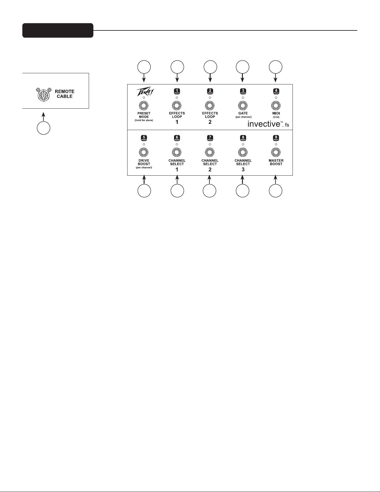
PEDAL
32 33 34 35 36
31
37 38 39 40 41
(31) Cable remoto
Se incluye un conector DIN de ocho clavijas para conectar el controlador de pie al amplicador ENTRADA/PIE
(38) a través del cable incluido en la caja.
(32) Modo predenido
Conmuta el controlador de pie entre el modo NORMAL (predeterminado, LED apagado) y el modo PREDEFI-
NIDO (LED rojo). Los otros LED serán rojos para el Modo Predenido, y verdes para el Modo Normal. (Vea la
sección “Uso del Modo Predenido” en la pág. 10)
(33) Bucle de efectos 1/Ajuste predenido N.° 1
Modo NORMAL: Activa el Bucle de Efectos 1.
Modo PREDEFINIDO: Selecciona el Ajuste predenido 1. Si se selecciona, el LED se encenderá en rojo.
(34) Bucle de efectos 2/Ajuste predenido N.° 2
Modo NORMAL: Activa el Bucle de Efectos 2.
Modo PREDEFINIDO: Selecciona el Ajuste predenido 2. Si se selecciona, el LED se encenderá en rojo.
(35) Compuerta/Ajuste predenido N.° 3
Modo NORMAL: Activa el circuito de la compuerta al usar el Canal 2 o 3.
Modo PREDEFINIDO: Selecciona el Ajuste predenido 3. Si se selecciona, el LED se encenderá en rojo.
(36) MIDI CC4 / Ajuste predenido N.° 4
Modo NORMAL: Esto enviará el controlador MIDI 4 con datos 0 (LED apagado) o 127 (LED encendido) al
equipo MIDI externo de control.
Modo PREDEFINIDO: Selecciona el Ajuste predenido 4. Si se selecciona, el LED se encenderá en rojo.
8
Page 82

(37) Amplicación de transmisión/ Ajuste predenido N.° 5
Modo NORMAL: Activa y desactiva la AMPLIFICACIÓN del canal actual. Al conmutar entre canales, recordará
el último ajuste de cada uno. El LED se encenderá en verde cuando se activa la AMPLIFICACIÓN de transmi-
sión.
Modo PREDEFINIDO: Selecciona el Ajuste predenido 5. Si se selecciona, el LED se encenderá en rojo.
(38) Selección de canal 1/Ajuste predenido N.° 6
Modo NORMAL: Selecciona el Canal 1. El LED se encenderá en VERDE. Si se presiona por segunda vez, el
canal regresará al ajuste anterior. Esto permite un cambio rápido entre dos canales con un solo interruptor.
Modo PREDEFINIDO: Selecciona el Ajuste predenido 6. Si se selecciona, el LED se encenderá en rojo.
(39) Selección de canal 2/Ajuste predenido N.° 7
Modo NORMAL: Selecciona el Canal 2. El LED se encenderá en VERDE. Si se presiona por segunda vez, el
canal regresará al ajuste anterior. Esto permite un cambio rápido entre dos canales con un solo interruptor.
Modo PREDEFINIDO: Selecciona el Ajuste predenido 7. Si se selecciona, el LED se encenderá en rojo.
(40) Selección de canal 3/Ajuste predenido N.° 8
Modo NORMAL: Selecciona el Canal 3. El LED se encenderá en VERDE. Si se presiona por segunda vez, el
canal regresará al ajuste anterior. Esto permite un cambio rápido entre dos canales con un solo interruptor.
Modo PREDEFINIDO: Selecciona el Ajuste predenido 8. Si se selecciona, el LED se encenderá en rojo.
(41) Amplicación maestra/ Ajuste predenido N.° 9
Modo NORMAL: Activa y desactiva la Amplicación maestra. El LED se encenderá en verde.
Modo PREDEFINIDO: Selecciona el Ajuste predenido 9. Si se selecciona, el LED se encenderá en rojo.
USO DEL MODO PREDEFINIDO
Cada uno de los 9 ajustes predenidos recuerda el canal actual, amplicación de transmisión encendida/apa-
gada, compuerta encendida/apagada, CC4 encendido/apagado, bucle de efectos encendido/apagado y ampli-
cación maestra encendida/apagada. Adicionalmente, recuerda la amplicación de transmisión y el estado de
la compuerta de los canales inactivos. De esta forma puede, por ejemplo, tener un ajuste predenido limpio
guardado sin amplicación de transmisión, y saber que al conmutar al Canal 2, se encenderá la amplicación de
transmisión.
El amplicador viene de fábrica con 9 ajustes predenidos predeterminados que puede modicar según lo desee.
Cuando la luz de MODO PREDEFINIDO está encendida, puede usar los otros 9 pedales para aplicar estos 9
ajustes predenidos. En cualquier momento puede pasar al modo NORMAL y realizar cambios a ese sonido.
Puede ser durante una función y no almacenarse de forma permanente, o para editar un ajuste predenido y
almacenarlo en uno de los 9 ajustes.
ALMACENAMIENTO DE AJUSTES PREDEFINIDOS
Para almacenar los ajustes actuales en uno de los 9 ajustes predenidos, debe comenzar por mantener presiona-
do el interruptor de MODO PREDEFINIDO por uno o dos segundos, y luego los demás LED parpadearán (con
excepción del ajuste predenido actual, que estará encendido jo, para recordarle con qué ajuste predenido está
trabajando). En este punto, puede presionar uno de los 9 interruptores de ajustes predenidos para almacenarlo
allí, o puede presionar el MODO PREDEFINIDO nuevamente para cancelar.
9
Page 83

Puede iniciarlo desde el modo PREDEFINIDO o desde el modo NORMAL. Después de guardar (o cancelar),
regresará al modo en que estaba anteriormente. De esta forma, puede congurar y almacenar 9 ajustes predeni-
dos sin ingresar al modo PREDEFINIDO si lo desea. Es típico congurar su sonido en modo NORMAL, luego
almacenar su creación en uno de los ajustes predenidos.
AMPLIFICACIÓN RÁPIDA:
Como se describe a continuación, en el modo predenido, los interruptores 1-9 activarán sus 9 ajustes prede-
nidos personalizados. Al presionar el interruptor del ajuste predenido ya activo, alternará el estado de la
Amplicación maestra. Esto permite una forma rápida de activar un ajuste predenido para un solista y am-
plicarlo rápidamente (¡simplemente toque el interruptor dos veces!). De lo contrario, debería tocarlo, luego
salir del modo predenido, luego tocar el interruptor de Amplicación maestra, ¡muchos pasos! (Por supuesto,
puede guardar el ajuste predenido con la amplicación activa, y luego al presionar por segunda vez se desactiva
la amplicación). Para poder ver el estado de Amplicación maestra en el modo predenido (LED rojos para
modo/predenido) el LED 9/amplicación maestra destellará en verde cuando se activa la amplicación. (En el
ajuste predenido 9, el color alternará entre rojo y verde para mostrar el número predenido y la Amplicación
maestra activada).
CONEXIÓN DE OTRO AMPLIFICADOR Y/O UNIDADES DE EFECTOS CON LA SALIDA DE MIDI
Puede conectar la salida de MIDI a la entrada de MIDI de otro Invective 120 para sincronizar los dos amplica-
dores. Con el pedal conectado al primer amplicador, los cambios que realice con el pedal (o el panel delantero)
se duplicarán en el segundo amplicador, si el segundo amplicador está en el mismo canal MIDI. Vea la sección
Programa de MIDI (pág. 13).
También puede conectar el MIDI del amplicador (o del segundo amplicador) a una unidad de efectos para
sincronizar los ajustes predenidos. Si la unidad de efectos puede almacenar ajustes predenidos, puede cambiar
automáticamente cuando activa los ajustes predenidos con el pedal.
Cuando se activa un ajuste predenido, envía ese comando de cambio de programa, seguido del estado del
controlador del CC4 (0 o 127 de acuerdo con la función del CC4) y el estado del controlador de CC10 (0 o 127
de acuerdo con la función de AMPLIFICACIÓN MAESTRA). Esto permite que la unidad de efectos de MIDI
responda a estos controladores y realice acciones como encender/apagar el retraso, etc. Los demás pedales tam-
bién envían mensajes de CC cuando se presionan, pero no en ajustes predenidos como los dos anteriores. (La
AMPLIFICACIÓN MAESTRA envía CC9 Y CC10. CC9 controla otros Invective, CC10 se sincroniza en el ajuste
predenido para el control de MIDI de otros dispositivos). Consulte la sección MIDI para ver los números de
CC generados por cada función.
10
Page 84

IMPLEMENTACIÓN DE MIDI
Este amplicador está diseñado para ser extremadamente funciona con el pedal de 10 botones incluido. El
enchufe del pedal de 8 clavijas también funciona como entrada MIDI estándar de 5 clavijas, para acoplarse a la
salida MIDI estándar de 5 clavijas. En ocasiones, el amplicador funcionará con otros tipos de controladores
de pie de MIDI, una PC en el estudio, o por medio de una plataforma automatizada de bastidores, o conectado
a otro Invective mediante MIDI. Esta es la información que necesita para conectar este amplicador con otros
dispositivos MIDI.
NOTA: La salida de MIDI enviará datos a otro Invective (para la sincronización de funciones), a una PC (para la
comunicación de 2 vías durante el control remoto o envío predenido), o a una unidad de efectos en el bucle de
efectos. Este enchufe no actúa como Salida/Paso. Los datos recibidos en la entrada de MIDI no resultan en datos
en la salida de MIDI a menos que sea un mensaje válido para este amplicador.
CC MIDI: Los controladores continuos de MIDI se utilizan para cambiar una función a la vez. Después de selec-
cionar un ajuste predenido (vea a continuación), las modicaciones a ese ajuste predenido se pueden realizar
con estos mensajes. Estos cambios en el amplicador o pedal generan estos mensajes de CC en la salida de MIDI.
Datos Bn CC# donde n=can-1 Datos: cualquiera
(Decimal) (Hex)
1 01h Seleccionar can 1
2 02h Seleccionar can 2
3 03h Seleccionar can 3
Datos: 00h-3Fh Datos: 40h-7Fh
4 04h * *
* El amplicador no responde a esto, pero lo envía de acuerdo con el ajuste predeterminado/pedal CC4 para
controlar el dispositivo externo de MIDI.
5 05h Amplicación de transmisión 1 APAGADA Amplicación de transmisión 1 ENCENDIDA
6 06h Amplicación de transmisión 2 APAGADA Amplicación de transmisión 2 ENCENDIDA
7 07h Amplicación de transmisión 3 APAGADA Amplicación de transmisión 3 ENCENDIDA
8 08h Amplicación de transmisión APAGADA Amplicación de transmisión ENCENDIDA (canal activo)
9 09h ** **
** El amplicador no responde a esto, pero lo envía de acuerdo con el ajuste predeterminado/pedal de Ampli-
cación maestra para controlar el dispositivo externo de MIDI.
10 0Ah Amplicación maestra APAGADA Amplicación maestra ENCENDIDA
11 0Bh FX Bucle 1 APAGADO FX Bucle 1 ENCENDIDO
12 0Ch FX Bucle 2 APAGADO FX Bucle 2 ENCENDIDO
13 0Dh Compuerta 2 APAGADA Compuerta 2 ENCENDIDA
14 0Eh Compuerta 3 APAGADA Compuerta 3 ENCENDIDA
15 0Fh Compuerta APAGADA Compuerta ENCENDIDA (canal activo, 2 o 3)
Ejemplo: B0 0A 7F permite la amplicación maestra (MIDI can 1)
11
Page 85

PROGRAMA MIDI
Los Cambios del programa MIDI se utilizan para seleccionar ajustes predenidos. Típicamente, un ajuste prede-
nido recongurará todas las funciones en el amplicador a la vez. (Los Programas 9-11 siguientes son excepcio-
nes, ya que solo afectan el canal).
NOTA: Estos mensajes, cuando se reciben, se enviarán el enchufe de salida de MIDI para la sincronización con
otro Invective.
NOTA: Los primeros nueve ajustes predenidos son sus ajustes predenidos personalizados. Activan lo que
almacene con el pedal.
CANAL AMPLIFICACIÓN DE TRANSMISIÓN AMPLIFICACIÓN MAESTRA CC 4 COMPUERTA FX BUCLE 1 FX BUCLE 2
Cn datos donde n=can-1 (el ajuste predenido se guarda para (el ajuste predenido se guarda para
(Decimal) (Hex) ...los tres canales) ...canales 2 y 3)
0 00h <-----------------------------------ajuste predenido 1-------------------------------------------------------->
1 01h <-----------------------------------ajuste predenido 2-------------------------------------------------------->
2 02h <-----------------------------------ajuste predenido 3-------------------------------------------------------->
3 03h <-----------------------------------ajuste predenido 4-------------------------------------------------------->
4 04h <-----------------------------------ajuste predenido 5-------------------------------------------------------->
5 05h <-----------------------------------ajuste predenido 6-------------------------------------------------------->
6 06h <-----------------------------------ajuste predenido 7-------------------------------------------------------->
7 07h <-----------------------------------ajuste predenido 8-------------------------------------------------------->
8 08h <-----------------------------------ajuste predenido 9-------------------------------------------------------->
Ejemplo: C0 00 selecciona el primer ajuste predenido (MIDI can 1)
Solo canal:
9 09h 1 sin cambio sin cambio sin cambio sin cambio sin cambio sin cambio
10 0Ah 2 sin cambio sin cambio sin cambio sin cambio sin cambio sin cambio
11 0Bh 3 sin cambio sin cambio sin cambio sin cambio sin cambio sin cambio
El Mapa de Fábrica básicamente es una lista extensa de ajustes predenidos jos con cada combinación de
función. Si automatiza una función desde una plataforma de MIDI, puede encontrar una combinación de estas
funciones en esta tabla de estilo binario.
NOTA: Debido a las limitaciones de MIDI, la función CC4 solo se controla por justes predenidos personaliza-
dos, no por el Mapa de Fábrica. No se cambiará ni eliminará.
en blanco = APAGADO; X = ENCENDIDO; n/a = no corresponde
Mapa de Fábrica: CANAL AMPLIFICACIÓN DE TRANSMISIÓN AMPLIFICACIÓN MAESTRA COMPUERTA FX BUCLE 1 FX BUCLE 2
(decimal) (hex)
12 0Ch 1 n/a
13 0Dh 2
14 0Eh 3
15 0Fh 1 X n/a
16 10h 2 X
17 11h 3 X
18 12h 1 X n/a
19 13h 2 X
20 14h 3 X
21 15h 1 X X n/a
22 16h 2 X X
23 17h 3 X X
24 18h 1 n/a
25 19h 2 X
12
Page 86

Mapa de Fábrica: CANAL AMPLIFICACIÓN DE TRANSMISIÓN AMPLIFICACIÓN MAESTRA COMPUERTA FX BUCLE 1 FX BUCLE 2
(decimal) (hex)
26 1Ah 3 X
27 1Bh 1 X n/a
28 1Ch 2 X X
29 1Dh 3 X
30 1Eh 1 X X n/a
31 1Fh 2 X X X
32 20h 3 X X X
33 21h 1 X X n/a
34 22h 2 X X X
35 23h 3 X X X
36 24h 1 n/a X
37 25h 2 X
38 26h 3 X
39 27h 1 X n/a X
40 28h 2 X X
41 29h 3 X X
42 2Ah 1 X n/a X
43 2Bh 2 X X
44 2Ch 3 X X
45 2Dh 1 X X n/a X
46 2Eh 2 X X X
47 2Fh 3 X X X
48 30h 1 n/a X
49 31h 2 X X
50 32h 3 X X
51 33h 1 X n/a X
52 34h 2 X X X
53 35h 3 X X X
54 36h 1 X n/a X
55 37h 2 X X X
56 38h 3 X X X
57 39h 1 X X n/a X
58 3Ah 2 X X X X
59 3Bh 3 X X X X
60 3Ch 1 n/a X
61 3Dh 2 X
62 3Eh 3 X
63 3Fh 1 X n/a X
64 40h 2 X X
65 41h 3 X X
66 42h 1 X n/a X
67 43h 2 X X
68 44h 3 X X
69 45h 1 X X n/a X
70 46h 2 X X X
71 47h 3 X X X
72 48h 1 n/a X
73 49h 2 X X
13
Page 87

Mapa de Fábrica: CANAL AMPLIFICACIÓN DE TRANSMISIÓN AMPLIFICACIÓN MAESTRA COMPUERTA FX BUCLE 1 FX BUCLE 2
(decimal) (hex)
74 4Ah 3 X X
75 4Bh 1 X n/a X
76 4Ch 2 X X X
77 4Dh 3 X X X
78 4Eh 1 X n/a X
79 4Fh 2 X X X
80 50h 3 X X X
81 51h 1 X X n/a X
82 52h 2 X X X X
83 53h 3 X X X X
84 54h 1 n/a X X
85 55h 2 X X
86 56h 3 X X
87 57h 1 X n/a X X
88 58h 2 X X X
89 59h 3 X X X
90 5Ah 1 X n/a X X
91 5Bh 2 X X X
92 5Ch 3 X X X
93 5Dh 1 X X n/a X X
94 5Eh 2 X X X X
95 5Fh 3 X X X X
96 60h 1 n/a X X
97 61h 2 X X X
98 62h 3 X X X
99 63h 1 X n/a X X
100 64h 2 X X X X
101 65h 3 X X X X
102 66h 1 X n/a X X
103 67h 2 X X X X
104 68h 3 X X X X
105 69h 1 X X n/a X X
106 6Ah 2 X X X X X
107 6Bh 3 X X X X X
14
Page 88

MIDI SYSEX
Los comandos exclusivos del sistema MIDI se usan para hacer todos los tipos de cosas que los comandos están-
dar no manejan. El Invective usa Sysex para funciones como respaldo o restauración de los 9 ajustes predenidos
del usuario, o para transferirlos a un segundo amplicador.
NOTA: Con excepción de lo señalado a continuación, estos mensajes, cuando se reciben, NO se transferirán al
enchufe de salida de MIDI. PERO si el mensaje no tiene un canal correspondiente de MIDI del primer ampli-
cador, lo TRANSFERIRÁ en caso de que el segundo amplicador coincida.
Solicitud de envío de los 9
Ajustes predenidos: F0h 00h 00h 1Bh 16h MIDI chan - 1 00h F7h
(0-15) (sin datos)
Cuando el amplicador recibe este comando, enviará un mensaje de envío de los 9 ajustes predenidos (ver a
continuación) al enchufe de salida de MIDI. Si se conecta a otro enchufe de entrada de Invective (y ese amplica-
dor está en el mismo canal de MIDI), los ajustes predenidos se copiarán a ese amplicador. Conecte la salida de
MIDI a un dispositivo de almacenamiento para respaldar sus 9 ajustes predenidos personalizados.
Envío de los 9 ajustes predenidos: F0h 00h 00h 1Bh 16h MIDI chan - 1 01h 36 bytes divididos F7h
(Recibir o enviar) (0-15) (ajustes predenidos 0-8)
Cuando el amplicador recibe este comando, reescribirá los 9 ajustes predenidos personalizados con los datos
en el comando (9 ajustes predenidos x 4 bytes divididos) - y TRANSFERIRÁ el envío en caso de que haya un
segundo amplicador conectado a la salida de MIDI (y en el mismo canal de MIDI). El amplicador ENVIARÁ
estos datos si recibe la solicitud anterior de envío. Adicionalmente, este envío se puede iniciar manualmente
manteniendo presionado el botón de Transmisión del Canal 1 y presionando el botón de selección de cana-
les.
ajuste actual
solicitud de envío F0h 00h 00h 1Bh 16h MIDI chan - 1 04h F7h
(0-15) (sin datos)
Cuando el amplicador recibe este comando, enviará un mensaje de envío de los ajustes actuales (ver a continua-
ción) al enchufe de salida de MIDI. El propósito principal es que un editor de PC reciba el ajuste sonoro actual
para sincronizar su retraso con el amplicador. Este ajuste podría ser diferente de los 9 ajustes predenidos si
han sido modicados en el modo Stomp y aún no ha sido almacenado.
ajuste actual
envío: F0h 00h 00h 1Bh 16h MIDI chan - 1 05h 4 bytes divididos F7h
(0-15) (ajuste sonoro actual)
El amplicador enviará este mensaje cuando se solicita, pero ignorará si se recibe. El ajuste actual se puede ajus-
tar fácilmente con los mensajes de cambio del controlador o del programa, de forma tal que este método no es
admitido como mensaje de entrada.
almacenamiento de ajustes predenidos: F0h 00h 00h 1Bh 16h MIDI chan - 1 06h ajuste predenido # - 1 F7h
(0-15) (0-8)
Cuando el amplicador recibe este comando, guardará el ajuste predenido sonoro actual en uno de los 9 ajustes
predenidos personalizados. El ajuste predenido sonoro podría modicarse a través de los comandos MIDI
CC. Una vez que el ajuste predenido es satisfactorio, se puede guardar en una de las 9 ubicaciones personali-
zadas con este comando. Sería el método de control remoto con una PC, o para crear una aplicación de editor/
bibliotecario. El mensaje se envía si hay un segundo amplicador en el mismo canal.
15
Page 89

FORMATO PREDEFINIDO
NOTA: Comandos que envían datos predenidos divididos HIGH byte/porción, luego BAJO.
Bit predenido: 15 14 13 12 11 10 9 8 7 6 5 4 3 2 1 0
Denición: n/a compuerta compuerta bucle de efectos 2, 1 n/a CTL 4 amplicación maestra 1 para can 3 1 para can 1 Amplicación superior
1 = activo 3 2 / CTL 9 0 para can 1 o 2 0 para can 2 o 3 c. 3, 2, 1
(n/a si el 3 está activo)
Ajustar canal MIDI canal predeterminado=1
a través de: F0h 00h 00h 1Bh 16h indistinto 0Dh canal - 1 F7h
(<= 0x7F) (0-15)
a través del pedal:
Mantenga presionado el pedal (9/Amplicación maestra) por 2 segundos para ingresar al modo de selección de
canal MIDI. Los LED en los pedales 1-8 destellarán. Luego puede elegir el canal MIDI 1-8 presionando uno de
ellos. También puede presionar 9/Amplicación maestra nuevamente para cancelar la operación.
Nota: El amplicador siempre responderá al pedal, pero el canal MIDI le permite
Responder selectivamente a los mensajes estándar de MIDI desde otros dispositivos.
16
Page 90

ESPECIFICACIONES
Sección del amplicador de potencia:
Potencia y carga nominales:
120 W (rms)a 16, 8, o 4 Ohmios
Potencia en la limitación:
(Típicamente a 5% THD, 1 kHz, línea de 120 VCA)
130 W (rms) a 16, 8, o 4 Ohmios
(Se debe reducir el sesgo para medir)
Respuesta a la frecuencia:
+0, -3 dB, 50 Hz a 20 kHz, a 100 W (rms) a 8 Ohmios
Murmullo y ruido:
Mayor a 78dB inferior a la potencia nominal
Ecualización del amplicador de potencia:
Presencia activa: +10 dB a 2 kHz
Resonancia activa: +10 dB a frecuencia resonante del gabinete
Consumo de energía:
400 W 50/60 Hz, 120 VCA (doméstico)
Sección del preamplicador:
Las especicaciones siguientes se han medido a 1kHz con los controles programados de la manera siguiente:
Ecualización baja y alta a 10
Ecualización media a 0
Post Ganancia a 10
Resonancia y presencia a 0 dB
Niveles nominales con la Preganancia a 5
Niveles mínimos con la Preganancia a 10
Todas las amplicaciones de ganancia APAGADAS
Compuerta APAGADA
Todos los bucles ENCENDIDOS
Amplicación maestra ENCENDIDA
Entrada de pre amplicador:
Impedancia: Muy alta Z, 470 K Ohmios
CANAL DE DISTORSIÓN:
Nivel de entrada nominal: -80 dBV, 0,1 mV (rms)
Nivel mínimo de entrada: -92 dBV, 0,025 mV (rms)
CANAL DE APLASTAMIENTO:
Nivel de entrada nominal: -50 dBV, 3,0 mV (rms)
Nivel mínimo de entrada: -66 dBV, 1,4 mV (rms)
Máximo nivel de entrada: -16 dBV, 45 mV (rms)
CANAL LIMPIO
Nivel de entrada nominal: -8.0dBV, 400mV (rms)
Nivel mínimo de entrada: -21 dBV, 90 mV (rms)
Máximo nivel de entrada: 0,0 dBV, 1,0 V (rms)
Efectos enviados:
Impedancia de carga: 1 k ohmios o mayor
Salida nominal: -10 dBV, 300 mV (rms)
17
Page 91

Efectos de retorno:
Impedancia: Muy alta Z, 470 K Ohmios
Nivel diseñado: -10 dBV, 300 mV (rms)
Zumbido y ruido del sistema al nivel nominal:
(Canal limpio; 20 Hz a 20 kHz sin ponderación)
Mayor a 78dB inferior a la potencia nominal
Ecualización:
Ecualización personalizada baja, media y alta de tipo pasivo
Enchufes auxiliares de suministro de energía (x2):
9 VCC (punta negativa) a 500 mA
Dimensiones: 26,7” de ancho x 11,8” de prof. x 10,0” de alto (678 mm de ancho x 300 mm de prof. x 254 mm de
alto)
Peso: 48,3 Lb (21,9 kg)
NOTA: Las especicaciones están sujetas a cambio sin previo aviso.
18
Page 92

Logo referenced in Directive 2002/96/EC Annex IV
The bar is the symbol for marking of new waste and
13 August 2005
Warranty registration and information for U.S. customers available online at
Peavey Electronics Corporation 5022 Hartley Peavey Drive Meridian, MS 39305 (601) 483-5365 FAX (601) 486-1278
20
www.peavey.com
www.peavey.com/warranty
or use the QR tag below
Features and specications subject to change without notice.
(OJ(L)37/38,13.02.03 and defined in EN 50419: 2005
is applied only to equipment manufactured after
80307558
 Loading...