

Page 1
Page 2
Intended to alert the user to the presence of uninsulated “dangerous voltage” within the product’s enclosure
A
A
CAUTION: Risk of electrical shock - DO NOT OPEN!
CAUTION: To reduce the risk of electric shock, do not remove cover. No user serviceable parts inside. Refer servicing to
qualified service personnel.
WARNING: To prevent electrical shock or fire hazard, do not expose this appliance to rain or moisture. Before using this
appliance, read the operating guide for further warnings.
that may be of sufficient magnitude to constitute a risk of electric shock to persons.
Intended to alert the user of the presence of important operating and maintenance (servicing) instructions in the
literature accompanying the product.
Este simbolo tiene el
A
A
PRECAUCION: Riesgo de corrientazo - No
PRECAUCION:
reparar. Deje todo mantenimiento a
ADVERTENCIA:
Antes de
A
A
ATTENTION: Risques de
ATTENTION:
aucune pi&e pouvant
AVERTISSEMENT: Afin de privenir les risques de
ou B l’humidite.
aislamiento dentro de la caja
corrientazo.
Este simbolo tiene el
y mantenimiento en la literatura que viene con el
Para
disminuir el riesgo de corrientazo, no
usar
Ce symbole est
dangereuse pouvant
Ce symbole est
l’utilisation et l’entretien (service) de l’appareil dans la littirature accompagnant le produit.
Para
este aparato, lea
utilis6
Afin
de
Ztre r6par6e
Avant d’utiliser cet appareil, lisez les avertissements supplementaires situ& dans le guide.
prop6sito
prop6sito
evitar corrientazos o peligro de incendio, no deje expuesto a la lluvia o humedad este aparato
m&s
pur indiquer 2 l’utilisateur la
Ztre d’intensitk
utilisi
pour indiquer j l’utilisateur qu’il ou qu’elle trouvera d’importantes instructions
choc
ilectrique - NE PAS OUVRIR!
reduire
le risque de
par l’utilisateur. Confier l’entretien g un personnel qualifie.
de alertar al usuario de la presencia de “(voltaje) peligro\o” quc no ticne
de1 product0
de alertar al usario de la presencia de instruccones importantes sobre la
10s
tecnicos calificados.
advertencias en la guia de
que puede tener
abra.
suffisante pour constituer un risque de
choc
electrique, ne pas enlever le couvercle. 11 ne se trouve B
producto.
operacicin.
dkcharge
una
magnitud suficiente coma
abra
la cubierta. No hay piezas adentro que cl usario
prksence & l’int&ieur
electrique ou de feu, n’exposez pas cet appareil h la pluie
de ce produit de tension non-isolie
choc klectrique.
para
constituir riesgo de
operacicin
pucda
l’interieur
SUI
Dieses Symbol
von Ausreichender
Dieses Symbol
A
VORSICHT: Risiko - Elektrischer Schlag! Nicht
VORSICHT:
keine Teile darin, die vom Anwender repariert werden
durchfiihren
ACHTUNG:
Feuchtigkeit ausgesetzt werden. Vor Inbetriebnahme unbedingt die Bedienungsanleitung lesen.
Handhabung und Wartung des Produkts betreffen.
Urn das
lassen.
Urn
sol1
den Anwender vor unisolierten geftihrlichen Spannungen innerhalb des
Sttirke
sind,
urn
einen elektrischen Schlag verursachen zu
sol1
den Benutzer auf wichtige Instruktionen in der Bedienungsanleitung aufmerksam
Gffnen!
Risiko eines elektrischen Schlages zu vermeiden, nicht die Abdeckung enfernen. Es befinden
einen elektrischen Schlag oder Feuergefahr zu vermeiden, sollte dieses
kijnnten.
Reparaturen nur von qualifiziertem Fachpersonal
kiinnen.
2
Gehtiuses warnen,
Ger%t
nicht dem Regen oder
machen,
die
die
sich
Page 3
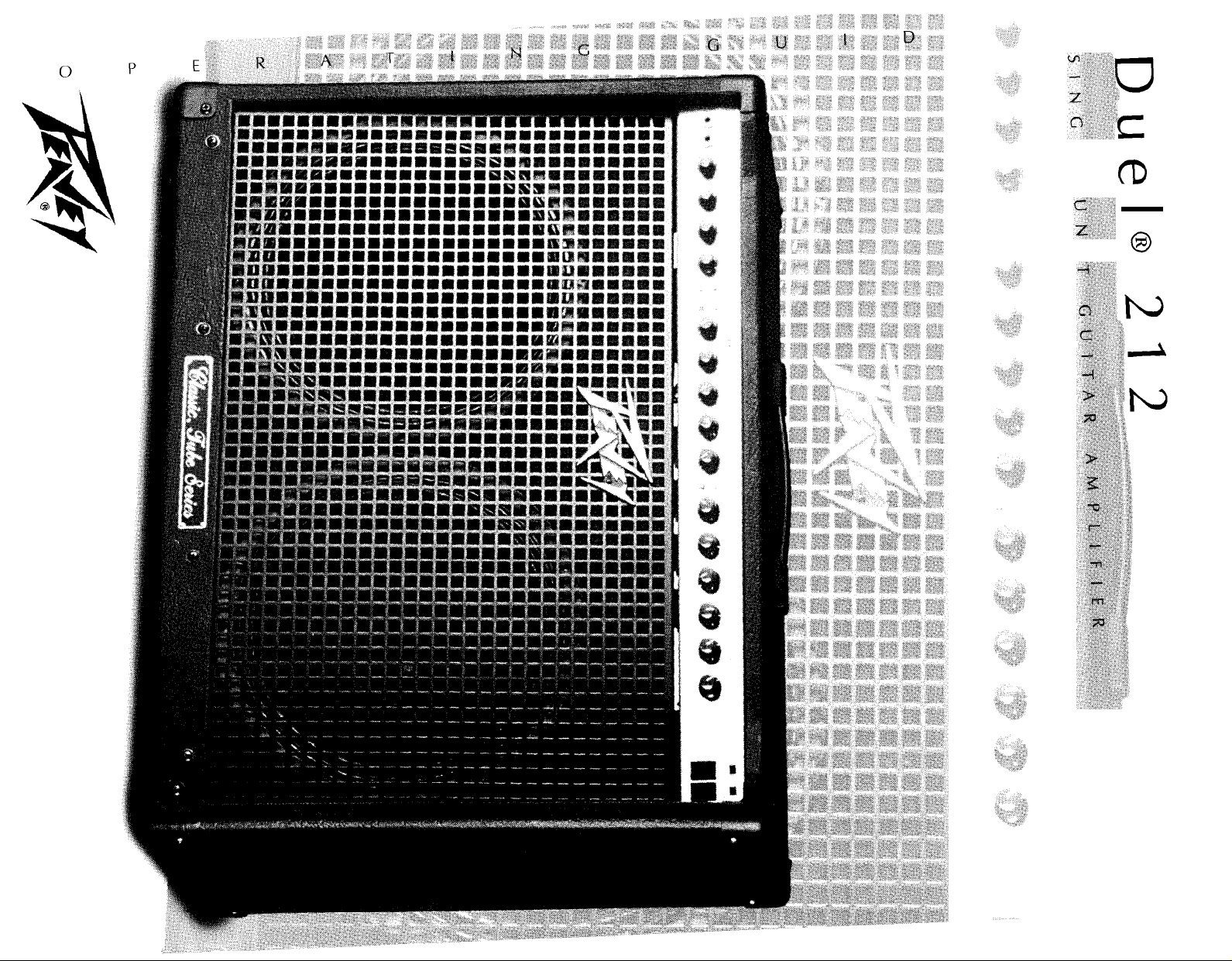
Congratulations on your purchase of the
Duel@
212 guitar amplifier. With the ever growing popularity
of the Classic 50 Series of amps, the Duel was designed to fulfill the needs of guitarists needing more
power, a “cleaner” clean sound, and more versatility in the lead channel. This newest addition to the
“Classic Tube Series” features individual equalization on each channel, Peavey’s patented resonance and
presence controls for the power amp, and a specially designed reverb reminiscent of many tube amps of
the
60’s.
For more vintage appeal, this amp incorporates the tremolo design from the Peavey Valverb,
and to bring the functionality into the
90’s,
we have included a footswitchable effects loop, as well. From
crystal clean to raunchy crunch, the Duel 212 is a very versatile amplifier for many guitarists’ playing
style . . .
PERFECT!
FEATURES
l All tube preamp and power amp
l
120WRMS
l Black TolexB covered cabinet
l External speaker capability
l Switchable impedance selector: 8, 4, 16 ohm
l Durable expanded black metal grille
l 2 heavy duty 12” speakers
. 2 separate channels, 3 band EQ switchable
l Footswitchable effects loop/level control
l Footswitchable reverb and tremolo
l
Master
volume control
l 4 button footswitch with LED indicators
Telex@ is a registered trademark of DiversiTech General.
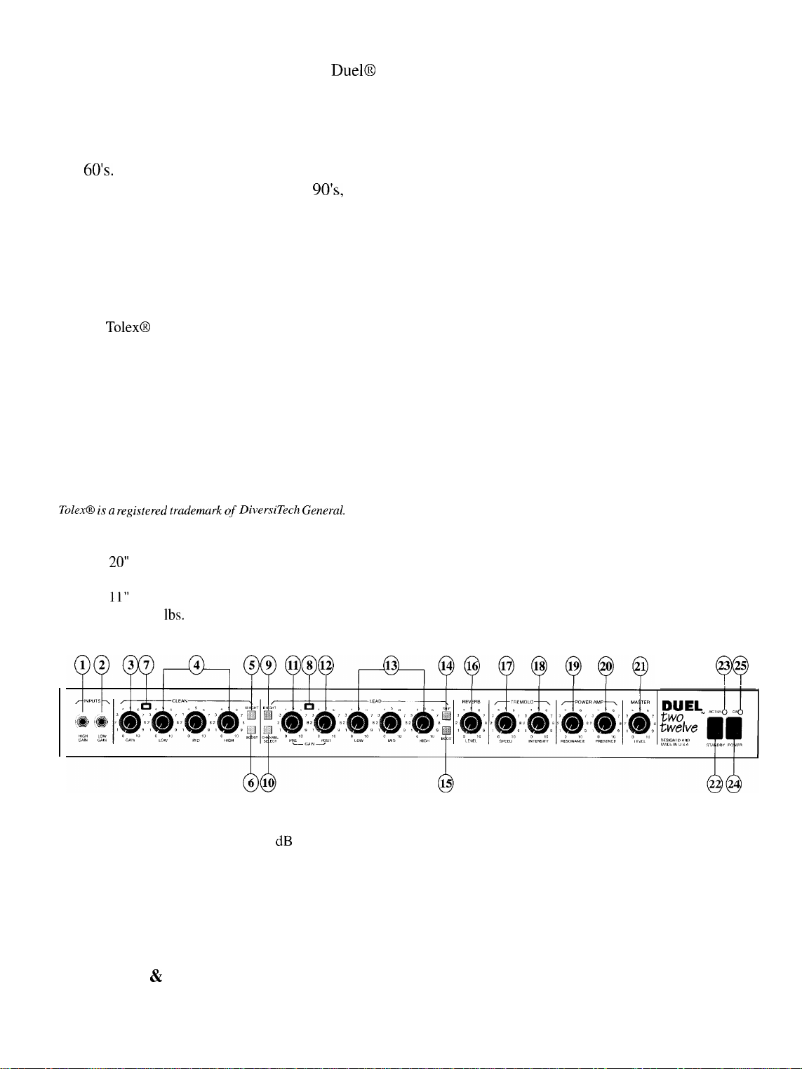
Cabinet Dimensions:
Height
Length 26”
Depth
Weight Total: 80
20”
11”
lbs.
3 25
Qo
HIGH GAIN INPUT (1)
Used for most electric guitars. It is 6 dB louder than the Low Gain input.
LOW GAIN INPUT (2)
Provided for instruments that have extremely high outputs, which can result in overdriving (distorting) the High Gain
input. If both inputs are used simultaneously, the output levels are the same (both are Low Gain).
GAIN (3)
Controls the volume of the clean channel.
LOW, MID, & HIGH EQ (4)
Passive tone controls that regulate the low, mid and high frequencies, respectively (clean channel).
3
Page 4

BRIGHT SWITCH (5)
Provides a preset boost to treble frequencies. To activate, depress the switch to its “in” position. The bright function
affects only the clean channel.
BOOST SWITCH (6)
Boosts the overall system gain of the clean channel. Depress to the “in” position to activate.
CLEAN LED (7)
Illuminates green when amp is switched to clean channel.
LEAD LED (8)
illuminates
red when amp is switched to lead channel.
BRIGHT SWITCH (9)
Provides a selective preset boost to high frequencies. To activate, depress the switch to its “in” position. The bright
function affects only the lead channel.
CHANNEL SELECT (10)
Allows selection of the clean and lead channel. NOTE: Channel selection may also be accomplished by the remote
footswitch. If remote selection is desired the Channel Select Switch must be in the “in” position.
PRE GAIN (11)
Controls the input volume level of the lead channel.
POST GAIN (12)
Controls the overall volume level of the lead channel. The final level adjustment should be made after the desired
sound has been achieved.
LOW, MID, & HIGH EQ (13)
Passive custom tone controls that regulate the low, mid, and high frequencies, respectively, of the lead channel only.
SHIFT (14)
Shifts and selects the frequencies at which the mid control operates.
BOOST (15)
Boosts the overall system gain of the lead channel. Depress to the “in” position to activate.
REVERB (16)
Reverberation is an echo effect. Rotate reverb level control to increase the effect. Remote footswitch can control ON/
OFF.
TREMOLO SPEED (17)
The speed control determines the rate with which the signal is modulated. This control varies the speed of the tremolo
master oscillator and should provide any speed desired for modern music. Clockwise rotation of the speed control
increases the speed of the modulation of the tremolo. The tremolo feature is defeatable from the remote footswitch.
TREMOLO INTENSITY (18)
The intensity control is used to vary the amount of amplitude modulation of the clean signal. It can be adjusted from
barely perceptible to almost 100% modulation. Clockwise rotation of the intensity control increases the depth of the
tremolo.
RESONANCE CONTROL (19)
Used to fine tune the low frequency range of the speaker enclosure by varying the damping factor of the amplifier at
low frequencies. This control can be set to boost the gain of the power amp in the low frequencies at the resonance/
attenuation point of the speaker cabinet to offset low end frequency dropout.
PRESENCE CONTROL (20)
Used to fine tune the high frequency range of the speaker enclosure by varying the damping factor of the amplifier at
high frequencies. This control can be set to boost the gain of the power amp in the high frequencies at the presence/
attenuation point of the speaker cabinet to offset high end frequency dropout.
4
Page 5
MASTER VOLUME (21)
Controls the overall volume level of the system. Once a desired balance of the clean and lead channel volume levels is
achieved, the entire system level may be increased or decreased with the Master Level Control.
STANDBY SWITCH (22)
Allows amp to be placed in standby or active mode. In standby mode the tubes remain hot, but the amplifier is not
operational. Eliminates warm up time, allowing the tubes to remain hot and ready for instantaneous operation.
ACTIVE LED (23)
The active LED indicator light will illuminate when the amp is in the operational mode. The standby switch (22) should
be switched to the active mode in order for the amp to be operational.
POWER SWITCH (24)
Supplies power to the unit. Depressed to the “ON” position, the power LED indicator (25) will illuminate indicating
power is being supplied to the unit.
POWER LED/ON (25)
Illuminates when AC Power is being supplied to the amp when the power switch (24) is depressed to the “ON” position.
SPEAKER OUTPUTS
12OW
RMSI44”
RMS
SPEAKER JACKS PARALLELED
40 MIN
400
0
120
bO HZ
WATTS
1
GND
0
“AC
rUSC
5A
REMOTE SWITCH
5
8
LEVEL
-wx
SEND RETURN
-
0
PRFAMP
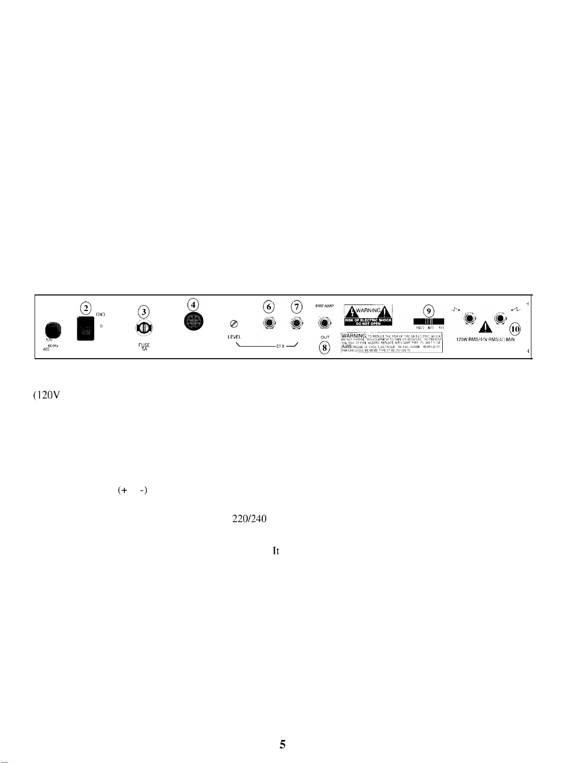
LINE CORD (1)
(12OV
units only) For your safety, we have incorporated a three-wire line (mains) cable with proper grounding facilities. It is not advisable to remove the ground pin under any circumstances. If it is necessary to use the amp without
proper grounding facilities, suitable grounding adaptors should be used. Greatly reduced shock hazard exists when the
unit is operated with the proper grounded receptacles.
GROUND SWITCH (2)
Three position, rocker-type switch which, for most applications, should be operated in the center (zero) position. If hum
or noise is noticed coming from the speaker with the ground switch in the center position, place the ground switch to
positive or negative (+ or -) to minimize hum. Should a hum/noise problem continue, consult your authorized Peavey
dealer, the Peavey factory, or a qualified service technician.
NOTE: The ground switch is not functional on 220/240 volt models.
FUSE (3)
A 5 amp fuse is located within the cap of the fuse holder. Tt must be replaced with the same type and value in order to
avoid damage to the equipment and to prevent voiding the warranty. If the amp repeatedly blows fuses, it should be
taken to a qualified service center for repair. WARNING: The fuse should only be replaced when the power cord has
been disconnected from its power source.
-f
-1
REMOTE FOOTSWITCH JACK (4)
Provided for the connection of the supplied remote footswitch. Footswitch is used to select the channel from clean to
lead and to select the effect, reverb, and tremolo on or off.
LEVEL (5)
Adjusts the voltage level of the effects loop. If the send level is too low for a particular effects device, turn the control
clockwise; if too high, counterclockwise.
EFFECTS SEND (6)
Output for supplying signals to external effects or signal processing equipment.
5
Page 6
EFFECTS RETURN (7)
Input for returning signals from external low-level effects or signal processing equipment.
NOTE: Signals are supplied to outboard effects or signal processing units by patching from the effects send jack (6)
output into the outboard unit(s) and back into the effects return (7) input using shielded cable with l/4” phone plugs.
Only non-gain effects devices (chorus, reverb, delay, etc.) should be used in the effects loop.
Remote (on/off) selection of outboard effects devices can be achieved using the footswitch.
PREAMP OUT (8)
The preamp out jack can be used to route the amplified signal to a mixing console, tape recorder, etc. Connect the
preamp output using a shielded cable to an input of the tape recorder, mixer, etc. This patch does not affect the operation of the amplifier.
IMPEDANCE SELECTOR SWITCH (9)
Use to select the appropriate impedance of the speaker enclosure(s). If two enclosures of equal impedance are used, the
switch should be set at one-half of that value (e.g., two 16 ohm enclosures: set switch to 8 ohms; two 8 ohm enclosures:
set switch to 4 ohms). When using only the internal speakers, the Impedance Selector Switch should be set to 16 ohm.
SPEAKER OUTPUTS (10)
Paralleled l/4” output jacks for connecting speaker enclosure(s) to the amplifier (minimum 4 ohms). When using more
than one enclosure, be sure to calculate the total impedance and set the impedance switch (9) accordingly. (See section
on Impedance Switch.)
IMPORTANT: Use only high quality, unshielded cable for speaker connections.
SPECIFICATIONS
HIGH
GAIN
LOW
GAIN
INPUTS
PREAMP
RESONANCE PRESENCE
L
PRE
SWITCH
LOGIC /T
-
f
L
PUSH
PUSH
BOOST
LEAD EQ
POST
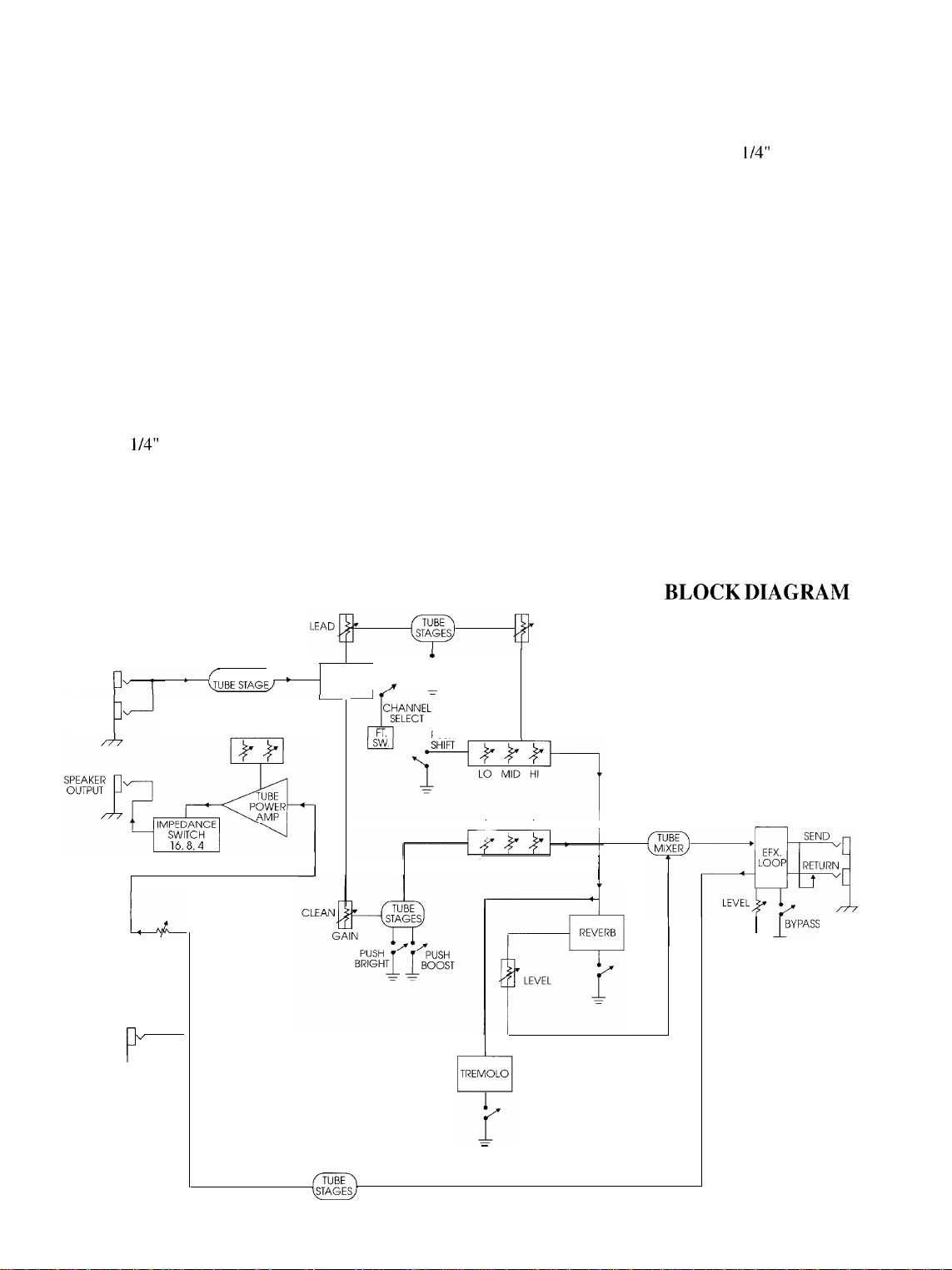
THIS
SHOWS SIGNAL FLOW
WITHIN THE UNIT. IN
ORDER TO THOROUGHLY
UNDERSTAND THE UNIT’S
FUNCTIONS, PLEASE
STUDY THE BLOCK
DIAGRAM CAREFULLY.
BLOCK DIAGRAM
PREAMP
OUT
P
MASTER
-
LEVEL
CLEAN EQ
LO MID HI
-
6
I
1
I”‘““”
Page 7
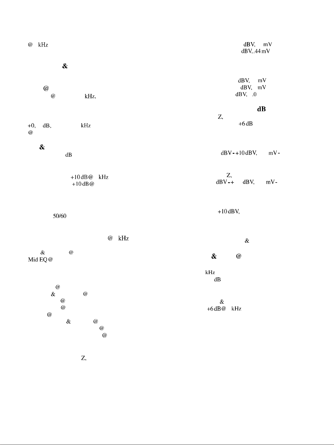
POWER AMPLIFIER SECTION
The following specs are measured
@
1 kHz with presence and resonance
at 0 and effects level at 10.
Lead Channel:
(Channel Select In)
Nominal Input Level:
Minimum Input Level:
-38 V
-67
dBV,
12 mV RMS
dBV, .44 mV
RMS
Rated Power & Load:
120 W RMS into 16, 8, or 4 ohms
Power @ Clipping:
Typically @ 5% THD, 1
120WRMS into
kHz,
16, 8,or4
120 V AC line
ohms
Frequency Response:
+O,
-3
dB,
50 Hz to 20 kHz
@
100 W RMS into 8 ohms
Hum & Noise:
Greater than 85 dB below rated power
Power Amp EQ:
Active presence:
Active resonance:
+10 dB @
+lO dB @
2 kHz
cabinet resonant frequency
Power Consumption:
(Domestic)
400 watts,
50/60
Hz, 120 V AC
PREAMP SECTION
The following specs are measured @ 1 kHz with the
controls preset as follows:
Low & High EQ @ 10
MidEQ @
Bright Out
Boost Out
Shift Out
Lead Posts @ 10
Presence & Resonance @ 0
Master Level @ 10
Effects Level @ 10
Reverb @ 0
Tremolo/Speed & Intensity @ 0
Nominal levels with pre gains @ 5
Minimum levels with pre gains @ 10
0
Clean Channel:
(Channel Select Out)
-17
dBV,
dBV,
dBV,
1 .O V RMS
40 mV RMS
8 mV RMS
Nominal Input Level:
Minimum Input Level: -42
Maximum Input Level: 0
Preamp Low Gain Input: (-6 dB Pad)
Impedance: High Z, 44 kilo-ohms
All levels are increased by +6
dB
Effects Send:
Load Impedance: 47 kilo-ohms or greater
Output Level: -10
dBV - +10 dBV,
300 mV - 3 V RMS
Effects Return:
Impedance Very high Z, 470 kilo-ohms
Input Level: -10
dBV - +
10
dBV,
300 mV - 3 V RMS
Preamp Output:
Load Impedance: 47 kilo-ohms or greater
Nominal Output:
+lO dBV,
3 V RMS
Remote Footswitch:
Special 4 button unit with LED indicators, Channel Select,
Effects Loop Bypass, Reverb & Tremolo Bypass
System Hum & Noise @ Nominal Level:
(Clean Channel)
20 Hz to 20
Greater than 75 dB below rated power
kHz
unweighted
Equalization:
Custom Low, Mid & High passive type EQ
Push Bright +6 dB @ 2
Push Boost increases Gain in midrange
Push Shift (Lead Channel Only) shifts frequency of mid
kHz
Preamp High Gain Input:
Impedance: Very high Z, 470 kilo-ohms
Page 8
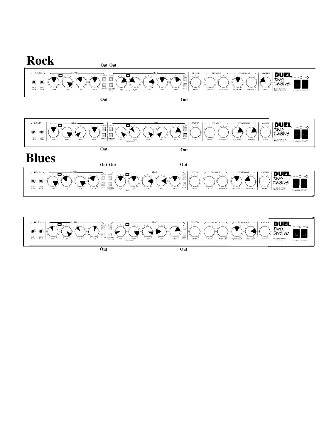
TONE SETTINGS
In
Metal
I
Country
Tone settings are general and will vary according to type of guitar, type and gauges
of strings, type of pickup and even type of pick. Personal taste, playing style, and type
In In
out out
In
In In
out
of music, greatly contribute to desired tonality.
In
out
In
out
out
Page 9

Felicitaciones por la adquisicion
de la serie de amplificadores clasicos Classic 50 Series, el amplificador Duel fue diseiiado para aquellos guitarristas que
requieren mayor potencia, una calidad de sonido a6n mas limpio y mas versatilidad en el canal primario. Esta nueva
adicion a la serie “Classic Tube Series” posee ecualizacion independiente para cada canal, controles de
preamplificacion para resonancia y presencia patentados por Peavey y reverberancia especialmente disefiada que
recordar a muchos de
clasico, este amplificador incorpora el mismo disefio de tremolo que el Peavey Valverb y para proporcionarle una
funcionalidad al dia con
coma
el cristal o estruendoso
singulares de muchos guitarristas diferentes.
10s
amplificadores con tubos de vacio de
10s aiios
de1
amplificador para
90,
incluye un
coma
el trueno, el Duel 212 es el amplificador IDEAL para adaptarse a
guitar-r-a
circuit0 de efectos conmutables por pedal. Al entregar un sonido claro
electrica Duel@ 212. Debido a la creciente popularidad
10s adios
60. Ademas, para lograr un atractivo aun mas
10s
hate
estilos
CARACTERiSTICAS
l Preamplificador y amplificador de potencia construido totalmente con tubos de vacio
l
120WRMS
l Gabinete recubierto de tolex negro
l Conexidn para altavoces externos
l Selector de impedancia conmutable para
l Parrilla de metal negro ampliado de larga
l 2 altavoces de 30 cm. (12 pulg.) de alta capacidad
l 2 canales independientes con ecualizacion conmutable para 3 bandas
l Circuit0 de efectos y control de nivel conmutable por pedal
l
Reverberation
l Control principal de volumen
l Pedal conmutador de 4 botones con diodos emisores de luz
y trkmolo conmutable por pedal
8,4
y 16 ohms
duration
Dimensiones de la caja:
Altura 50 cm (20 pulg.)
Largo
Profundidad
Peso total: 36 kg (80 lbs.)
66 cm (26 pulg.)
28 cm ( 11 pulg
.)
Consulte
delantero en la
10s
diagramas
seccih
de
inglbs
de1
panel
de este manual.
HIGH GAIN INPUT (Entrada de ganancia alta) (1)
Se usa para la mayoria de las guitarras electricas. Tiene 6 dB mas volumen que la entrada de baja ganancia.
LOW GAIN INPUT (Entrada de baja ganancia) (2)
Se suministra para instrumentos que tienen una salida extremadamente alta, la cual puede causar la sobrecarga
(distorsidn) de la entrada de alta ganancia. Si se usan ambas entradas simultaneamente, el nivel de salida es el mismo
(ambos son de baja ganancia).
GANANCIA (GAIN) (3)
Controla
ECUALIZACI6N
Controles pasivos de tonalidad para regular las frecuencias bajas, medias y altas
el volumen
de1
canal limpio (Clean).
BAJA, MEDIA Y ALTA (4)
de1
canal limpio (Clean).
BRIGHT SWITCH (Interruptor de brillo) (5)
Proporciona un impulso preajustado a las frecuencias de tiple. Para activar, oprima el interruptor a la
adentro”. La
funcidn
de brillo solamente afecta el canal “limpio”.
position
“hacia
9
Page 10

CONMUTADOR DE REFUERZO (BOOST) (6)
Refuerza la ganancia general
de1
sistema para el canal limpio (clean). Oprimir para activarlo.
DIODO DEL CANAL LIMP10 (CLEAN) (7)
Se ilumina de color
Verde
para indicar que el amplificador est6 conmutado al canal limpio (Clean).
DIODO DEL CANAL PRIMARIO (LEAD) (8)
Se ilumina de color
Verde
para indicar que el amplificador esta conmutado al canal primario (Lead).
BRIGHT SWITCH (Interruptor de brillo) (9)
Proporciona un impulso de +8 dB a las frecuencias agudas. Para activar empuje el interruptor hacia dentro.
SELECTOR DE
Permite seleccionar entre el canal limpio (Clean) y el canal primario (Lead).
canales por medio
conmutaci6n desde el pedal de control remoto.
PRE GAIN (Control
Controla la entrada de volumen
POST GAIN (Control de ganancia posterior
Controla el volumen general
sonido deseado.
ECUALIZACI6N
Controles pasivos de tonalidad -ajustables por el usuario- para regular las frecuencias bajas, medias y altas
primario (Lead) solamente.
CANALES
de1
pedal de control. El selector de canales debe encontrarse oprimido para poder realizar la
de1
(CHANNEL SELECTOR) (10)
NOTA:
Tambikn se puede seleccionar
preamplificador) (11)
de1
canal solista.
de1
preamplificador) (12)
de1
canal solista. El ajuste final de nivel debe hacerse despuks de que se
haya
BAJA, MEDIA Y ALTA (13)
obtenido
de1
canal
SHIFT (Desplazamiento de frcuencias) (14)
Este control desplaza y selecciona las frecuencias en las cuales opera el control de medio.
REFUERZO (BOOST) (15)
Refuerza la ganancia general
REVERB
Este control ajusta el nivel de reverberacibn (efecto de eco) para el canal, y se debe usar con el control maestro de
reverberacibn. Cuando se conectan efectos externos,
“Effects Send” (Envio de efectos) en la secci6n maestra.
(Reverberacih)
de1
sistema para el canal primario (Lead). Oprimir para activarlo.
(16)
kste
control ajusta el nivel de la
sefial
en el enchufe hembra
10s
el
VELOCIDAD DEL TRkMOLO (TREMOLO SPEED) (17)
Control de velocidad usado para determinar el grado de modulaci6n de la
oscilador principal
Girar este control hacia la derecha para aumentar la velocidad de modulaci6n
desactivarse desde el pedal de control remoto.
de1
trkmolo y es capaz de proporcionar todas las velocidades deseadas para la mtisica moderna.
sefial.
Este control varia la velocidad
de1 tkmolo.
El trkmolo puede
INTENSIDAD DEL TRliMOLO (TREMOLO INTENSITY) (18)
Control de intensidad usado para variar la amplitud de la modulaci6n de la
casi imperceptible hasta cerca de un 100% de modulaci6n. Girar este control hacia la derecha para aumentar la
profundidad de modulaci6n
de1
trkmolo.
sefial
limpia. Puede ajustarse desde un nivel
CONTROL DE RESONANCIA (RESONANCE) (19)
Utilizado para realizar ajustes precisos
factor de amortiguacibn de las frecuencias bajas
ganancia de las frecuencias bajas
compensar la caida de frecuencia
de1
rango de frecuencias bajas de la caja de altavoces a traves de la
de1
amplificador. Se puede utilizar este control para reforzar la
de1
preamplificador en el punto de resonancia/atenuacibn de la caja de altavoces para
de1
espectro bajo.
variacicin de1
CONTROL DE PRESENCIA (PRESENCE) (20)
Utilizado para realizar ajustes precisos
factor de amortiguacibn de las frecuencias altas
de1
rango de frecuencias altas de la caja de altavoces a travks de la variaciiin
de1
amplificador. Se puede utilizar este control para reforzar la
10
del
de1
Page 11

ganancia de las frecuencias altas
compensar la caida de frecuencia
de1
preamplificador en el punto de
de1
espectro alto.
VOLUMEN PRINCIPAL (MASTER) (21)
Controla el
canal limpio y
volumen general
de1
primario, se puede aumentar o disminuir el volumen de todo el sistema por medio de este control.
de1
sistema. Una vez que se logra el equilibrio deseado entre
presencia/atenuacion
de la caja de altavoces para
10s
niveles de volumen
de1
STANDBY SWITCH (Interruptor de
Este interruptor le permite a su aparato estar en
“standby”
precalentamiento de
instantaneamente.
10s
tubos permanecen calientes, pero el amplificador no esta en
10s
tubos de vacio, permitiendo que estos permanezcan calientes y listos para funcionar
condicih
condition
de espera) (22)
de “espera” o la
condition
operation.
de active. En la
Elimina la necesidad de
condition
DIODO ACTIVO (23)
El diodo de estado
de estado en espera (standby) (22) debe activarse para que el amplificador se encuentre en la modalidad de
funcionamiento.
active
debe permanecer iluminado cuando el amplificador se encuentre funcionando. El conmutador
POWER SWITCH (Interruptor de corriente) (24)
Oprima el interruptor a la
indicando que la unidad esta recibiendo corriente alterna.
position
“hacia dentro” (encendido). La luz roja
de1
pilot0 (indicador) se encendera
POWER LED (LED indicador de corriente) (25)
Se ilumina cuando el equip0 recibe la corriente altema.
LINE CORD (120 V PRODUCTS ONLY) (Cable de corriente
Para su
polo a tierra bajo ninguna circunstancia, se recomienda un adaptor en
corrientazos.
protection
hemos incorporado un cable de 3 polos con polo a
para
120 v solamente) (1)
tier-r-a.
No es recomendable remover la pata
case
necesario. Esto reducira ruidos y peligrosos
de1
GROUND SWITCH (Interruptor de tierra) (2)
Un interruptor tipo balancin de tres posiciones que, en la mayoria de las aplicaciones, debe ser operado en su
de1
centro o cero (0). Puede haber situaciones cuando un zumbido audible salga
ajuste la
NOTA:
tecnico de servicio calificado. EL INTERRUPTOR DE TIERRA NO FUNCIONA EN LOS MODELOS DE 220/240
VOLTIOS.
position de1
Si el problema de ruido continua, consulte su representante autorizado de Peavey, la fabrica de Peavey, o
interruptor de tierra a positivo o negativo (+ o -) o hasta que el ruido disminuya.
de1
altavoz. Si esta
situation
position
occure,
un
FUSE (Fusible) (3)
El fusible se encuentra localizado dentro de la capsula
REEMPLAZAR CON
ANULAMIENTO DE LA GARANTIA. Si el aparato quema
conectado a un tomacorriente con el voltaje adecuado, si esto es correcto, entonces
un tknico
ATENCION: Antes de reemplazar el fusible quemado, cerciorese de que el aparato esta completamente desconectado
de1
tomacorriente.
autorizado.
UN0
DEL MISMO
TIP0
de1
portafusible. Si el fusible se quema o falla, SE DEBERA
Y VALOR, PARA EVITAR
10s
fusible repetidamente, cerciorese de que esta
DAR0
AL APARATO Y EL
desconectelo
y Ilevelo a revision por
11
Page 12

ENCHUFE DEL PEDAL DE CONTROL REMOTO (4)
Usado para conectar el pedal de control remoto. El pedal de control se utiliza para seleccionar entre el canal limpio y el
primario y para activar o desactivar el efecto, la
reverberation
y el tremolo.
NIVELES (5)
Ajusta el nivel de voltaje para el circuit0 de efectos. Si el nivel de salida es insuficiente para un dispositivo de efectos
en particular, girar el control hacia la derecha, y si es demasiado alto, girarlo hacia la izquierda.
EFFECTS SEND
Salida para enviar sefiales a efectos externos o equipos procesadores de
(Envio
de efectos) (6)
sefial.
EFFECTS RETURN (Retorno de efectos) (7)
Entrada para el retorno de sefiales procedentes de equipos de efectos externos de bajo nivel o de procesadores de
NOTA:
salida (6) y regresan de esta a traves
independiente debe crearse usando cables blindados de
deben utilizar efectos que no proporcionan ninguna ganancia de
etc.
El pedal de control
amplificador.
PREAMP OUT
La salida
salida
interconexion
IMPEDANCE SELECTOR SWITCH (Interruptor de
Se utiliza para seleccionar la impedancia apropiada de
misma impedancia, se debe ajustar el interruptor a la mitad de este valor. Si se utilizan dos
ajustar el selector de impedancia a 8 ohmios. Cuando use solamente las bocinas internas, el selector de impedancia
debera estar puesto en la
Las sefiales se dirigen a una unidad independiente procesadora de sefiales para efectos desde el enchufe de
de1
enchufe de retorno (7). El circuit0 cerrado con la unidad de efectos
6,4
mm
(l/4
de pulg.) para telefono. En el circuit0 de efectos se
sefial,
tales
coma 10s
remoto permite activar y desactiv
(Salida
de1
preamplificador puede usarse para mandar la
de1
preamplificador, utilizando un cable blindado, a una entrada de la grabadora, mezclador, etc. Esta
no afecta la
de
preamplificador)
operation de1
position
de 16 ohms.
amplificador.
‘ar
10s
efectos
de la unidad de efectos independientes conectada
(8)
serial
a una consola de mezcla, grabadora, etc. Conecte la
seleccih
10s
altavoces. Por ejemplo, si se utilizan dos altavoces de la
de impedancia) (9)
de core,
batles
reverberation,
de 16 ohmios, se debe
retardo,
SALIDAS PARA ALTAVOCES (SPEAKER OUTPUTS) (10)
Enchufes de 64 mm
ohms). Al usar mas de una caja de altavoces, asegurarse de calcular la impedancia total y regular el conmutador de
impedancia (9) de acuerdo al case. (Ver la
IMPORTANTE: Usar solamente cables no blindados de alta calidad para realizar la conexion de
(l/4
de pulg.) en paralelo utilizados para conectar altavoces externos al amplificador (minim0 de 4
section
correspondiente al conmutador de impedancia).
10s
altavoces.
sefial.
al
12
Page 13

Felicitations ! Vous venez d’acheter un amplificateur pour guitares
serie d’amplificateurs Classic 50, le modele Duel est
puissance superieure, d’un son d’une plus grande
ne de la serie <Classic Tube
Series>>
possede des
conGu
<<clarte>>
fonctions
pour repondre aux besoins des guitaristes en quete d’une
et d’une plus grande
d’egalisation individuelle sur chaque canal, des
d’effets de resonance et de presence brevetees par Peavey pour
Duel@
212. Face a la popularite croissante de la
l’amplificateur
conception speciale rappelant les amplificateurs a tubes des annees 60. Pour
integre le
install6
un
systeme
egalement
tremolo du Valverb Peavey tout en
des effets
command&
par pedale. De la purete du cristal aux grincements percutants, le Duel 212 est
amplificateur aux possibilites infinies qui
convient
possedant
l’aspect fonctionnel des annees 90, puisque nous avons
au style de tous les guitaristes.. .PARFAIT
CARACTERISTIQUES
l Tous les preamplificateurs
l
120WRMS
l
Boitier
recouvert de tolex noir
l Haut-parleur externe
l Commutateur de selection d’impedance
l Grille elargie en metal noir resistant
l 2 haut-parleurs de 30 cm tres puissants
l 2 canaux separes, 3 bandes d’egalisation sur commutation
l Commande de niveau/boucle d’effets a pedale
l Reverberateur et tremolo
l Commande du volume centrale
l Pedale de
commande a
a
tubes et les amplificateurs de puissance.
8,4
et 16 ohms
a
pedales de
commande
4 boutons avec voyants DEL
flexibilite
du canal principal. Ce dernier
commandes
de puissance et un reverberateur de
renforcer
ce c&e retro, cet amplificateur
!
Dimensions du boitier
Hauteur
Longueur
Profondeur
Poids total
:
:
:
:
HIGH GAIN INPUT
Cette prise s’utilise avec la plupart des guitares electriques. Elle donne un gain superieur de 6 dB a
LOW GAIN INPUT
Cette prise accepte les instruments a tres haut niveau de sortie qui causeraient de la saturation (distorsion) sur
:
50 cm
66 cm
28 cm
36 kg
Veuillez vous
situ6
dans la section en langue anglaise de ce manuel.
(Entrk
(Entr6
r6fker
haut gain) (1)
faible Gain) (2)
au “front panel line art”
l’entree
“Low Gain”,
l’entree
“High Gain”. Si les deux entrees sont utilisees simultanement, les niveaux sont alors equivalents (“Low Gain”).
GAIN (3)
Controle
*
Canal qui ne produit aucune deformation du son emis par la guitare.
le volume du canal clean*.
EGALISATEUR DES BASSES, MOYENNES ET HAUTES FREQUENCES (4)
Commandes passives de tonalite qui ritglent les basses, moyennes et hautes frequences, respectivement, du canal Clean.
BRIGHT SWITCH
Produit un
renforcement
(Sklecteur
des frequences aigues. Pour activer, enclenchez le bouton a la position “In”. Cette fonction de
brillance n’affect que le canal “Clean”.
de brillance) (5)
13
Page 14

COMMUTATEUR D’AUGMENTATION (6)
Augmente le gain d’ensemble du canal Clean. Pour activer cette fonction, appuyer en position marche
(<<in>>).
DEL CLEAN (7)
Ce voyant vert s’allume lorsque l’amplificateur est branch6 sur le canal Clean.
DEL PRINCIPAL (8)
Ce voyant rouge s’allume lorsque l’amplificateur est branch6 sur le canal principal.
BRIGHT SWITCH (Selecteur de brillance) (9)
Produit un
brillance n’affecte que le canal “Lead”.
renforcement
des frequences aigues. Pour actiber, enclenchez le
bouton
a la position “In”. Cette fonction de
SELECTION DE CANAL (10)
Permet de selectionner le canal Clean ou principal. REMARQUE : la selection des canaux peut aussi se faire a partir
d’une pedale de commande a distance. Pour selectionner la commande a distance, le commutateur de selection de canal
doit
etre en position marche.
PRE GAIN (11)
Controle
le niveau de volume a
l’entree
sur du canal “Lead”.
POST GAIN (12)
Commande le volume general du canal “Lead”. Le reglage final de niveau
sonorite desiree a l’aide des autres reglages.
doit
etre
effectue
apres avoir obtenu la
EGALISATEUR DES BASSES, MOYENNES ET HAUTES FREQUENCES (13)
Commandes passives de
principal uniquement.
tonalite
qui
reglent
les basses, moyennes et hautes frequences, respectivement, du canal
SHIFT (Selection) (14)
Determine la bande de frequences sur laquelle agit la commande “Mid”.
AUGMENTATION (15)
Augmente le gain d’ensemble du canal principal. Pour activer cette fonction, appuyer en position
REVERB TO MAIN
La reverberation est un effet
l’intensite de l’effet. L’interrupteur au pied optionnel peut controler la mise en circuit ou hors circuit (“On/Off).
(Rherbkation)
d’echo.
Tournez dans le sens du mouvement des aiguilles
(16)
dune
<<marche>>.
montre pour augmenter
VITESSE TREMOLO (17)
La commande de vitesse determine le taux de modulation du signal. Elle modifie la vitesse de I’oscillateur central
tremolo et offre toutes les vitesses desirees pour la musique moderne. La rotation horaire de cette commande permet
d’augmenter la vitesse de modulation du tremolo. La fonction de tremolo peut etre annulee a partir de la pedale de
commande a distance.
du
INTENSITE DU TREMOLO (18)
La commande d’intensite du tremolo set-t a varier la modulation d’amplitude du signal Clean. Elle peut etre reglee sur
une modulation pratiquement imperceptible a une modulation de presque 100 %. La rotation horaire de la commande
de vitesse permet d’augmenter la profondeur du tremolo.
COMMANDE DE RESONANCE (19)
Regle
precisement
l’amplificateur a basses frequences. Cette commande peut etre reglee pour augmenter le gain de l’amplificateur de
puissance dans les basses frequences au point de
l’interruption des basses frequences.
l’amplitude des basses frequences du coffre de l’enceinte en variant le facteur d’attenuation de
resonnance/attenuation du coffre du
haut-parleur pour compenser
COMMANDE DE PRESENCE (20)
Regle precisement l’amplitude des hautes frequences du coffre de l’enceinte en variant le facteur d’attenuation de
l’amplificateur a hautes frequences. Cette commande peut etre reglee pour augmenter le gain de l’amplificateur de
14
Page 15

puissance dans
les
hautes frequences au point de presence/attenuation du
coffre
du haut-parleur pour compenser
l’interruption des hautes frequences.
VOLUME CENTRAL (21)
Controle le volume general du systeme. Une fois atteint I’equilibre du volume desire des canaux Clean et principal, tout
le niveau du systeme peut etre augment6 ou diminue depuis la commande de volume central.
STANDBY SWITCH
Permet de selectionner
(Sklecteur
l’etat
de l’ampli: mode “Active” (actif] ou mode “Standby” (attente). En position “Standby”,
attente) (22)
l’amplificateur ne fonctionne pas mais les lampes (“tubes”) restent chaudes pour permettre de le remettre en service
sans delai. (Elimine le temps de mise en route en permettant aux tubes de rester chauds et
p&s a
fonctionner
immediatement).
SIGNAL DEL
Le voyant DEL
doit etre bascule en mode
ACTIF
actif
(23)
s’allume lorsque l’amplificateur est en mode de fonctionnement. Le commutateur de reserve (22)
actif
pour que l’amplificateur soit operationnel.
POWER SWITCH (Interrupteur d’alimentation) (24)
Mettre l’interrupteur en position “On”.
courant.
POWER LED (DEL
S’allume quand
l’unite
t6moin
recoit l’alimentation CA.
FUSE
F315.4
La lampe temoin rouge (DEL) s’illumine indiquant que
d’alimentation) (25)
PREAMP
0
i
RFMOTE SWITCH
LE”El
SEND
-EFX -
RETURN
0
OUT
8
l’appareil
-P-
12OW RMS/WV
SPEAKER JACKS
est aliment6 en
SPFAKER OLJTPUTS
@,@;
RMS 4Ll
PARALLELtD
i
MIN
LINE CORD (120V products only) (Cordon d’alimentation pour appareils
12OV
seulement) (1)
Pour votre securite, nous avons incorpore un cable d’alimentation secteur a 3 fils avec mise-a-terre appropriee. II n’est
pas
recommande
d’enlever la broche de mise-a-terre appropriee, utilisez des adaptateurs de mise-a-terre convenables.
Une bonne mise-a- terre amoindrit le bruit de fond et reduit grandement les risques de choc.
GROUND SWITCH
Commatateur rotatif a trois positions devant, la plupart du temps,
situations un bruit de ronflement ou un bourdonnement
(S6lecteur
de mise B terre) (2)
audib!c>
&tre
en position centrale (zero). Dans certaines
peut provenir des haut-parleurs de puissance. Dans ce
cas, bougez le selecteur de mise a terre jusqu’en position positive ou negative (+ ou -) ou jusqu’a ce que le bruit
diminue.
NOTE: Si le probleme de bbruit persiste, consultez votre
detaillant
autorise Peavey, la fabrique Peavey, ou
un
technicien de service qualifie. LE SELECTEUR DE MISE A TERRE NE FONCTIONNE PAS SUR LES APPAREILS
220/240
VOLT.
FUSE (Fusible) (3)
Le fusible se trouve a l’interieur de son support. Si le fusible grille, IL DOIT ETRE REMPLACE PAR UN FUSIBLE
DE MEME TYPE ET MEME VALEUR POUR EVITER TOUT DOMMAGE A L’APPAREIL ET EVITER
D’ANNULER LA GARANTIE. Si le fusible grille de facon repetee, apportez l’appareil a un centre de service qualifie
pour reparation. AVERTISSEMENT: LE FUSIBLE NE DOIT ETRE REMPLACE QUE LORSQUE LE CORDON
D’ALIMENTATION EST DE
BRANCH6
DE LA SOURCE D’ALIMENTATION.
FICHE DE PEDALE DE COMMANDE A DISTANCE (4)
Permet la connexion de la pedale de commande a distance (fournie). La pedale de commande est utilisee pour
selectionner le canal Clean ou principal et pour mettre en marche ou arreter l’effet, le reverberateur et le tremolo.
15
Page 16

NIVEAU (5)
Regle la tension de la boucle d’effets. Si le niveau d’envoi est trop bas pour un dispositif d’effets speciaux, tournez la
commande
EFFECTS SEND (Envoi d’effets) (6)
Prise de sortie servant & fournir des signaux a des appareils externes de traitement de signal ou d’effets.
dans le sens des aiguilles d’une montre ; s’il est trop haut, tournez-la dans le sens contraire.
EFFECTS RETURN (Retour d’effets) (7)
Prise d’entree pour signaux provenant d’appareils externes de traitement de signal ou d’effets a bas niveau.
REMARQUE : les signaux sonores sont transmis aux unites d’effets ou de traitement des signaux en raccordant la
sortie de la fiche d’envoi effets (6) aux unites du
blind6 comportant des fiches de 63 mm. Seuls les effets sans gain (choeur, reverberation, retard, etc.) doivent etre
utilises avec la boucle d’effets.
La selection marche/arret (on/off) des effets du
bo”itier,
puis a l’entree de retour des effets
boytier
peut se faire a partir de la pedale de
(7),
a l’aide d’un cable
commande
a distance.
PREAMP OUT (Sortie
La sortie preampli peut etre utilisee pour amener le signal a une table de mixage, un magnetophone, etc. Utilisez des
cables
blind&
pour brancher la sortie du preampli a l’entree d’un magnetophone, d’un melangeur, etc. Ce branchement
n’affecte pas le fonctionnement de l’amplificateur.
IMPEDANCE SELECTOR SWITCH (Selecteur
Sert a selectionner l’impedance appropriee pour le ou les haut-parleurs. Par exemple, si deux haut-parleurs de meme
impedance sont utilises, le selecteur doit etre regle a la moitie de cette valeur. Si deux baffles de 16 ohms sont utilises,
le selecteur d’impedance
d’impedance
doit
etre place sur la position 16 Ohm.
prkampli)
doit
etre regle 8 ohms. Note: Si les haut-parleurs internes sont utilises, le selecteur
(8)
d’impbdance)
(9)
SORTIE DES HAUTS-PARLEURS (10)
Fiches de sortie de 63 mm mises en parallele pour connecter le ou les coffre(s) des enceintes a
mum de 4 ohms). Lorsque plusieurs
d’impedance (9) en consequence. (Voir la section sur le commutateur d’impedance.)
TfimPORTANT :
n’utiliser que des cables non blind& de haute qualite pour connecter les haut-parleurs.
coffres
sont utilises, veiller Bcalculer l’impkdance totale et regler le commutateur
l’amplificateur
(mini-
16
Page 17

Wir begliickwunschen Sie zum Erwerb des Duel@ 212 Gitarrenverstarkers. In Anbetracht der immer
groRer
werdenden
Popularitat der Classic 50 Verstarkerreihe haben wir den Duel fur die besonderen Anforderungen des Gitarristen nach
einem sauberen, unverzerrten Klang und einer
Model1 der
patentierte Resonanz- und
Classic
Tube Series“ zeichnet sich besonders durch individuelle Entzerrung der Kanale, Peaveys
Prasenzfilter fur
griiI3eren
Vielseitigkeit des ,,Lead”-Kanals konstruiert. Dieses neue
die Endstufe und eine besonders konstruierte Nachhall-Reminiszenz
aus,
die an die Rohrenverst;irker der 60er Jahre erinnert. Fur einen klassischen Klang wurde das Tremolo-Design des
Peavey Valverbs integriert, und
ein
FuBpedal
vielseitiger
schaltbare Effektschleife hinzugefiigt. Von kristallklar bis rauchig dunkel - der Duel 2 12 ist ein
Verstarker,
der den Wunschen und Anforderungen von Gitarristen der verschiedensten Stilrichtungen
Rechnung tragt . . . einfach PERFEKT
urn
der Funktionalitat der 90er Jahre Rechnung zu tragen, haben wir such eine durch
!
FEATURES
l Reiner Rohren-Vor- und Endverstarker
l
120WRMS
l Mit schwarzem, Tolex-beschichtetem Gehause
l Externe Lautsprecherfahigkeit
l
Impedanzwahlschalter fur 8,4
l Strapazierftihiger, erweiterter Metallgrill
l Zwei 30 cm Hochleistungslautsprecher
l Zwei separate Kanale, umschaltbarer 3 Band-Equalizer
l
uber Ft.&pedal
l
uber FL&pedal
l Hauptlautstarkeregler
l FuBpedal mit vier Tasten und LED-Anzeige
umschaltbare
umschaltbarer Nachhall- und Tremolo-Effekt
und 16 Ohm
Effektschleife/Pegelregelung
Gehauseabmessungen:
Hohe 50 cm
Lange 66 cm
Tiefe
Gesamtgewicht:
28 cm
36 kg
Siehe Diagramm der Frontplatte im englischen Teil des Handbuchs.
HIGH GAIN INPUT (1)
Dieser Eingang kann fur die meisten elektrischen Gitarren verwendet werden. Er ist 6 dB empfindlicher als der Low
Gain Input.
LOW GAIN INPUT (2)
Dieser Eingang ist fur die Instrumente vorgesehen, die ein besonders hohes Ausgangssignal erzeugen. Falls beide
Eingange gleichzeitig benutzt werden, sind die Ausgangssignale gleich (beide sind dann Low Gain).
LEISTUNGSVERSTiiRKUNG (3)
Regelt die
TIEF-, MITTEL- UND HOCHTON-EQUALIZER (4)
Passive Tonregler, mit denen die tiefen (low), mittleren (mid) und hohen (high) Frequenzen fur den Clean-Kanal
ausgesteuert werden.
BRIGHT SWITCH (5)
Bringt einen voreingestellten Boost der hohen Frequenzen. Zum Einschalten den Schalter in die “in” Position bringen.
Die “Bright”-Funktion wirkt nur auf den “Clean” Kanal.
Lautstarke
des
Clean“-Kanals.
17
Page 18

BOOST-SCHALTER (6)
Verstarkt die Gesamtverstarkung des Clean-Kanals. Drucken Sie den Schalter ein
aktivieren.
(JN“-Position)
,
urn
den Boost zu
CLEAN LED (7)
Diese LED leuchtet
geschaltet wird.
grtin
auf, wenn der Verstarker auf den Clean-Kanal (unverzerrte Signalwiedergabe, ohne Effekte)
LEAD LED (8)
Diese LED leuchtet rot auf, wenn der Verstgrker auf den Lead-Kanal (durch Effekte veranderte Signalwiedergabe)
geschaltet wird.
BRIGHT SWITCH (Bright-Schalter) (9)
Hebt die hohen Frequenzen urn einen voreingestellten Wert an. Wenn sich der Schalter in der eingedriickten “In”Position befindet, ist Bright aktiviert. Die Bright Funktion beeinslusst nur den Lead-Kanal.
KANALAUSWAHL (10)
Mit dieser Taste kann zwischen Clean- und Lead-Kanal umgeschaltet werden. Bitte beachten Sie, das der
entsprechende Kanal
gewahlt
werden
such
sol], mu13
tiber das
der Kanalauswahlschalter gedriickt sein (,,IN”-Position).
FL&pedal
ausgewahlt werden kann. Wenn der Kanal tiber FuBpedalsteuerung
PRE GAIN (11)
Kontrolliert den Vorstufenpegel des Lead-Kanals.
POST GAIN (12)
Kontrolliert den gesamten
sollte vorgenommen werden, nachdem der gewiinschte Sound eingestellt ist.
Lautstarke-pegel
des Hauptkanals (Mastervolumen). Die endgtiltige
Lautstarkeregelung
TIEF-, MITTEL- UND HOCHTON-EQUALIZER (13)
Passive Tonregler, mit
ausgesteuert werden.
denen
die
tiefen
(low), mittleren (mid) und hohen (high) Frequenzen
fur
den Lead-Kanal
SHIFT (14)
Verschiebt und selektiert die Frequenzen, in denen der Mittenregler arbeitet.
BOOST-SCHALTER (15)
Verstarkt die Gesamtverstarkung des Lead-Kanals. Driicken Sie den Schalter ein (,,IN”-Position),
aktivieren.
urn
den Boost zu
REVERB TO MAIN (16)
Reverb ist ein Echoeffekt. Drehen im Uhrzeigersinn verstarkt den Effekt. Auch mit dem als
FuBschalter ein oder auszuschalten.
Zubehor erhsltlichen
TREMOLO-GESCHWINDIGKEIT (17)
Die Geschwindigkeitsregelung bestimmt die Geschwindigkeit, mit der das Signal verandert wird. Dieser Regler
verandert die Geschwindigkeit des Tremolo-Steueroszillators und ist in der Lage, jede fur moderne Musik gewiinschte
Geschwindigkeit zu liefern. Wenn der Geschwindigkeitsregler im Uhrzeigersinn gedreht wird, erhoht sich die
Geschwindigkeit der Modulation des Tremolos. Die Tremolo-Eigenschaft kann iiber die FuDpedalsteuerung uberbriickt
werden.
TREMOLO-1NTENSIT;iT (18)
Mit der Intensitatsregelung wird der Grad der Amplitudenmodulation des Clean-Signals gesteuert. Sie kann von kaum
wahrnehmbar bis auf fast 100 % Veranderung eingestellt werden. Drehung im Uhrzeigersinn verandert die Tiefe des
Tremolos.
RESONANZREGELUNG (19)
Der tiefe Frequenzbereich der Lautsprecherbox wird feinabgestimmt, indem der Dampfungsfaktor des Verstarkers
tiefe Frequenzen variiert wird. Dieser Regler kann so eingestellt werden,
Frequenzen der Endstufe am
der tiefen Frequenzen auszugleichen.
Resonanz-/Dampfungspunkt
der Lautsprecherbox verstarkt wird,
daI3
der Verstarkungsfaktor fur die tiefen
urn
den Frequenzabfall
18
fur
Page 19

PRASENZFILTER (20)
Der hohe Frequenzbereich der Lautsprecherbox wird feinabgestimmt, indem der Dampfungsfaktor des Verstgrkers
hohe Frequenzen variiert wird. Dieser Regler kann so eingestellt werden, da8 der Verstarkungsfaktor
Frequenzen der Endstufe am
hohen Frequenzen auszugleichen.
Prasenz-/Dampfungspunkt
der Lautsprecherbox verstarkt wird,
urn
fur
die hohen
den Frequenzabfall der
fur
HAUPTLAUTSTARKEREGLER
Mit diesem Regler wird der Gesamtlautstarkepegel des Systems eingestellt. Sobald Sie die gewunschte Balance
zwischen Lead- und Clean-Kanallautstarke eingestellt haben, konnen Sie den Lautstarkepegel
fiber
den Hauptlautstarkeregler erhohen oder verringern.
STANDBY SWITCH (22)
Ermoglicht es, den Verstarker mit abgeschaltetem Tonsignal betriebsbereit zu halten. In der “Standby” Betriebsart
werden die Rohren weiter beheizt, das Signal ist jedoch abgeschaltet.
(Die Aufwarmphase entfgllt, und die Rohren bleiben aufgeheizt und somit einsatzbereit.)
AKTIV-LED (23)
Die Aktiv-LED leuchtet auf, wenn der Verstarker in Betrieb ist. Damit der Verstarker immer betriebsbereit bleibt, sollte
der
Standby“-Schalter gedruckt
POWER SWITCH (Netzschalter) (24)
Bringen Sie den Schalter auf die ON-Position. Die rote Kontrollampe (LED) leuchtet und zeigt an, da0 das Gerat
eingeschaltet ist.
POWER LED (25)
1st erleuchtet, wenn das Gerat eingeschaltet ist und mit Strom versorgt wird.
2
0
E
220-230"
N
-
m-240
"
N
50 60 HZ
400 WATTS
24D"r.d
/
01
'\
werden (Active Mode).
3
0
-
\
/'
FUSE
F315A
REMOTE SWITCH
(21)
LEVEL
-EFX
SEND RETURN
-
fur
das gesamte System
SPEAKER
+*
--\
s,*@,;
l?DW RMSId4V RMS 40
SPEAKER JACKS PARALLELLD
"IJTPUTS
MIN
t
i
LINE CORD (120V products only) (Nur
Zu Ihrer Sicherheit haben wir das
Umstanden empfehlenswert den Erdungskontakt des Anschlufikabels zu losen. Falls es notwendig sein sollte, das
Equipment ohne die vorgesehene Erdung zu betreiben empfiehlt sich die Verwendung eines Grounding Adaptors. Die
geringsten Storgerausche und die hochste Sicherheit vor elekti ischen Schlagen wird jedoch durch die Benutzung
vorgesehenen
GROUND SWITCH (2)
Der Ground-Schalter funktioniert
FUSE (3)
Die Sicherung befindet sich innerhalb der Kappe des Sicherungshalters. Wenn die Sicherung durchbrennt, MUSS SIE
DURCH EINE DES GLEICHEN TYPS UND MIT DEM GLEICHEN WERT ERSETZT WERDEN, UM DAS
GERAT ZU SCHUTZEN UND DIE GARANTIELEISTUNGEN ZU ERHALTEN. Wenn am Verstarker wiederholt die
Sicherung durchbrennt,
WARNUNG: SICHERUNGSWECHSEL NUR BEI ABGEZOGENEM NETZKABEL VORNEHMEN!
BUCHSE FijR DIE FUSSPEDALBEDIENUNG (4)
Hier wird die mitgelieferte FuBpedalbedienung angeschlossen. Mit dem
Kanal gewechselt und auBerdem die Effektschleife, Nachhall und Tremolo ein- und ausgeschaltet werden.
SPANNUNGSNIVEAU (5)
Mit diesem Regler wird das Spannungsniveau der Effektschleife eingestellt. Wenn das Sendeniveau fur ein bestimmtes
Effektgerat
Erdungsmoglichkeiten
mul3
zu niedrig ist, drehen Sie den Regler im Uhrzeigersinn; falls es zu hoch ist, entgegen dem Uhrzeigersinn.
Get-at
mit einem dreiadrigen geerdeten Negzkabel versehen. Es ist unter keinen
erreicht.
nicht
bei den 220/240 Volt-Modellen.
das Gerat in eine qualifizierte Fachwerkstatt.
bei
120
Volt-Geriiten)
19
(1)
F&pedal
der
kann zwischen Lead- und Clean-
Page 20

EFFECTS SEND (6)
Ausgang fiir externe Effekte.
EFFECTS RETURN (7)
Eingang fiir riickfiihrende Signale von niederohmigen Effekten oder Signal-Prozessoren.
HINWEIS: Signale werden an
Buchse (6) (Ausgang) mit den AulSeneinheiten und diese wiederum mit dem Effekt-Rtickkehr-Eingang (7) verbunden
werden. Verwenden Sie dazu ein
versttirkungsfreie
uber
das FuBpedal kiinnen die AuBeneffekte ein- und ausgeschaltet werden.
PREAMP OUT (Vorstufenausgang) (8)
Dieser Ausgang kann zum
Verbinden Sie den Ausgang mit Hilfe eines abgeschirmten Kabels mit dem Eingang des entsprechenden Gergtes. Dieser
AnschluB beeinflufit die Funktionen des Verstgrkers nicht.
Effektgerite
AurSeneffekte
6,4
mm starkes, abgeschirmtes Kabel mit Klinkensteckern. Sie sollten nur
mit der Effektschleife einsetzen (Chorus, Nachhall, Verziigerung usw.).
AnschlulS
des Verstgrkers an einen Mixer, eine Bandmaschine, etc. verwendet werden.
oder signalverarbeitende Einheiten iibergeben, indem die
Effekt-Sende-
IMPEDANZ WAHLSCHALTER (9)
Hiermit wird die entsprechende Lautsprecher-Impedanz eingestellt. Bei der Verwendung von z.B. zwei Lautsprechern
gleicher Impedanz sollte der Schalter auf die
angeschlossen werden, sollte der Impedanz-Wahlschalter auf 8 Ohm eingestellt sein. Hinweis: Wenn nur die internen
Lautsprecher verwendet werden,
mu13
der Impedanzauswahlschalter auf 16 Ohm gestellt werden.
Hilfte
des Werts eingestellt werden. Wenn zwei 16 Ohm Boxen
LAUTSPRECHERAUSGiiNGE (10)
Parallele
als ein Lautsprecher eingesetzt werden
Impedanzschalter (9) entsprechend ein. (Lesen Sie dazu
WICHTIG: Benutzen Sie fiir die Lautsprecherverbindungen nur qualitativ hochwertige, nicht abgeschirmte Kabel.
6,4
mm Ausgangsbuchsen,
urn
Lautsprecher an den Verstgrker anzuschliel3en (Minimum 4 Ohm). Wenn mehr
~011,
berechnen Sie vorher die Gesamtimpedanz, und stellen Sie den
such
die Erkltirungen zum Impedanzschalter).
20
Page 21

For further information on other Peavey products,
ask your Authorized Peavey Dealer for the
appropriate Peavey catalog/publication:
Bass Guitars
Guitars
Bass Amplification
Guitar Amplification
Sound Reinforcement Enclosures
Microphones
Keyboards
DJ
Lighting
Mixers, Powered/Non-Powered
Accessories/Cables
Effects Processors
AxcessTM
The Peavey
Monitor@ Magazine
Key
IssuesTM
Low
PMTM
Magazine
Wear
BeatTM
DownTM
21
Page 22

THIS LIMITED WARRANTY VALID ONLY WHEN PURCHASED AND REGISTERED IN THE UNITED STATES OR CANADA. ALL EXPORTED PRODUCTS
ARE SUBJECT TO WARRANTY AND SERVICES TO BE SPECIFIED AND PROVIDED BY THE AUTHORIZED DISTRIBUTOR FOR EACH COUNTRY.
Ces clauses de garantie ne sont vaiables qu’aux Etats-Unis et au Canada. Dans tour les autres pays, les clauses de garantie et de maintenance sont
fixees par le distributeur national et assuree par
Diese Garantie ist nur in den USA and Kanada gultig. Alle Export-Produkte sind der Garantie
unterworfen. Esta garantia es
comprados en el extranjero, estan sujetos a
PEAVEY ELECTRONICS CORPORATION (“PEAVEY”) warrants this product, EXCEPT for covers, footswitches, patchcords, tubes and meters, to be free from
defects in material and workmanship for a period of one (1) year from date of purchase, PROVIDED, however, that this
original retail purchaser and is subject to the conditions, exclusions, and limitations hereinafter set forth:
If this product contains tubes or meters, Peavey warrants the tubes or meters contained in the product to be free from defects in material and workmanship for
a period of ninety (90) days from date of purchase; PROVIDED, however, that this limited warranty is extended only to the original retail purchaser and is also
subject to the conditions, exclusions, and limitations hereinafter set forth.
These limited warranties shall be void and of no effect, if:
a.
The first purchase of the product is for the purpose of resale; or
b.
The original retail purchase is not made from an AUTHORIZED PEAVEY DEALER; or
c.
The product has been damaged by accident or unreasonable use, neglect, improper service or maintenance, or other causes not arising out of defects in
material or workmanship: or
d.
The serial number affixed to the product is altered, defaced, or removed.
In the event of a defect in material and/or workmanship covered by this limited warranty, Peavey will:
a.
In the case of tubes or meters, replace the defective component without charge.
b.
In other covered cases (i.e., cases involving anything other than covers, footswitches, patchcords, tubes or meters), repair the defect in material or
workmanship or replace the product, at Peavey’s option; and provided, however, that, in any case, all costs of shipping, if necessary, are paid by you, the
purchaser.
THE WARRANTY REGISTRATION CARD SHOULD BE ACCURATELY COMPLETED AND MAILED TO AND RECEIVED BY PEAVEY WITHIN FOURTEEN (14)
DAYS FROM THE DATE OF YOUR PURCHASE.
In order to obtain service under these warranties, you must:
a.
Bring the defective item to any PEAVEY AUTHORIZED DEALER or AUTHORIZED PEAVEY SERVICE CENTER and present therewith the ORIGINAL
PROOF OF PURCHASE supplied to you by the AUTHORIZED PEAVEY DEALER in connection with your purchase from him of this product.
If the DEALER or SERVICE CENTER is unable to provide the necessary warranty service you will be directed to the nearest other PEAVEY AUTHORIZED
DEALER or AUTHORIZED PEAVEY SERVICE CENTER which can provide such set-vice.
b.
Ship the defective item, prepaid, to:
including therewith a complete, detailed description of the problem, together with a legible copy of the original PROOF OF PURCHASE and a complete return
address. Upon Peavey’s receipt of these items:
If the defect is remedial under these limited warranties and the other terms and conditions expressed herein have been complied with, Peavey will provide the
necessary warranty service to repair or replace the product and will return it, FREIGHT COLLECT, to you, the purchaser.
Peavey’s liability to the purchaser for damages from any cause whatsoever and regardless of the form of action, including negligence, is limited to the actual
damages up to the greater of $500.00 or an amount equal to the purchase price of the product that caused the damage or that is the subject of or is directly related
to the cause of action. Such purchase price will be that in effect for the specific product when the cause of action arose. This limitation of liability will not apply to
claims for personal injury or damage to real property or tangible personal property allegedly caused by Peavey’s negligence. Peavey does not assume liability for
personal injury or property damage arising out of or caused by a non-Peavey alteration or attachment, nor does Peavey assume any responsbility for damage to
interconnected non-Peavey equipment that may result from the normal functioning and maintenance of the Peavey equipment.
UNDER NO CIRCUMSTANCES WILL PEAVEY BE LIABLE FOR ANY LOST PROFITS, LOST SAVINGS, ANY INCIDENTAL DAMAGES, OR ANY CONSE-
QUENTIAL DAMAGES ARISING OUT OF THE USE OR INABILITY TO USE THE PRODUCT, EVEN IF PEAVEY HAS BEEN ADVISED OF THE POSSIBILITY
OF SUCH DAMAGES.
THESE LIMITED WARRANTIES ARE IN LIEU OF ANY AND ALL WARRANTIES, EXPRESSED OR IMPLIED, INCLUDING, BUT NOT LIMITED TO, THE
IMPLIED WARRANTIES OF MERCHANTABILITY AND FITNESS FOR A PARTICI!!.AR USE; PROVIDED, HOWEVER, THAT IF THE OTHER TERMS AND
CONDITIONS NECESSARY TO THE EXISTENCE OF THE EXPRESSED, LIMITED WARRANTIES, AS HEREINABOVE STATED, HAVE BEEN COMPLIED
WITH, IMPLIED WARRANTIES ARE NOT DISCLAIMED DURING THE APPLICABLE ONE-YEAR OR NINETY-DAY PERIOD FROM DATE OF PURCHASE OF
THIS PRODUCT.
SOME STATES DO NOT ALLOW LIMITATION ON HOW LONG AN IMPLIED WARRANTY LASTS, OR THE EXCLUSION OR LIMITATION OF INCIDENTAL
OR CONSEQUENTIAL DAMAGES, SO THE ABOVE LIMITATIONS OR EXCLUSIONS MAY NOT APPLY TO YOU. THESE LIMITED WARRANTIES GIVE YOU
SPECIFIC LEGAL RIGHTS, AND YOU MAY ALSO HAVE OTHER RIGHTS WHICH MAY VARY FROM STATE TO STATE.
THESE LIMITED WARRANTIES ARE THE ONLY EXPRESSED WARRANTIES ON THIS PRODUCT, AND NO OTHER STATEMENT, REPRESENTATION,
WARRANTY, OR AGREEMENT BY ANY PERSON SHALL BE VALID OR BINDING UPON PEAVEY.
In the event of any modification or disclaimer of expressed or implied warranties, or any limitation of remedies, contained herein conflicts with applicable law,
then such modification, disclaimer or limitation, as the case may be, shall be deemed to be modified to the extent necessary to comply with such law.
Your remedies for breach of these warranties are limited to those remedies provided herein and Peavey Electronics Corporation gives this limited warranty only
with respect to equipment purchased in the United States of America.
1.
Mail the completed WARRANTY REGISTRATION CARD to:
a. Keep the PROOF OF PURCHASE. In the event warranty service is required during the warranty period, you
identification card issued by Peavey Electronics Corporation.
2.
IMPORTANCE OF WARRANTY REGISTRATION CARDS AND NOTIFICATION OF CHANGES OF ADDRESSES:
a. Completion and
the REGISTRATION CARD will help ensure that you are contacted and properly notified.
b. Notice of address changes - If you move from the address shown on the WARRANTY REGISTRATION CARD, you should
address so as to facilitate your receipt of any bulletins or other forms of notification which may become necessary in connection with any condition that may
require dissemination of information or correction.
3.
You may contact Peavey directly by telephoning (601) 483-5365.
mailing
valida
solamente cuando el
CONDITIONS, EXCLUSIONS, AND LIMITATIONS OF LIMITED WARRANTIES
of WARRANTY REGISTRATION CARDS - Should notification become necessary for any
lul
seion la legislation envigueur.
product0
es
las
garantias y servicio que cada distribuidor autorizado determine y ofrezca en
PEAVEY
INSTRUCTIONS - WARRANTY REGISTRATION CARD
PEAVEY ONE-YEAR LIMITED
OO-DAY
LIMITED WARRANTY ON TUBES AND METERS
PEAVEY ELECTRONICS CORPORATION
PEAVEY ELECTRONICS CORPORATION
MERIDIAN, MISSISSIPPI
comprado
WARRANTY/REMEDY
International Service Center
326 Hwy. 11 & 80 East
MERIDIAN, MS 39301
POST OFFICE BOX 2898
en E.U. continentales o en Canada. Todos
OR
39302-2898
und
dem Service des lmporteurs des jewelligen Landes
limited
warranty IS extended only to the
will
need this document. There will be no
condition
10s productos
10s
diferentes paises.
that may require
notify
Peavey of the change of
que
Sean
correct!on,
22
Page 23

IMPORTANT SAFETY INSTRUCTIONS
WARNING: When using electric products, basic cautions should always be followed, including the following.
1.
Read all safety and operating instructions before using this product.
All safety and operating instructions should be retained for future reference.
2.
Obey all cautions in the operating instructions and on the back of the unit.
3
_
.
All operating instructions should be followed.
4.
This product should not be
5- .
This product should be located so that its position does not interfere with its proper ventilation. It should not be placed
6.
used
near water, i.e.,
wall or placed in a built-in enclosure that will impede the flow of cooling air.
This product should not be placed near a source of heat such as a stove, radiator, or another heat producing amplifier.
7.
8.
Connect only to a power supply of the type marked on the unit adjacent to the power supply cord.
Never break off the ground pin on the power supply cord. For more information on grounding, write for our free booklet “Shock
9.
Hazard and Grounding.”
Power supply cords should always be handled carefully. Never walk or place equipment on power supply cords. Periodically check
10.
cords for cuts or signs of stress, especially at the plug and the point where the cord exits the unit.
I I.
The power supply cord should be unplugged when the unit is to be unused for long periods of time.
If this product is to be mounted in an equipment rack, rear support should be provided.
12.
Metal parts can be cleaned with a damp rag. The vinyl covering used on some units can be cleaned with a damp rag or an ammonia-
13.
based household cleaner if necessary. Disconnect unit from power supply before cleaning.
14.
Care should be taken so that objects do not fall and liquids are not spilled into the unit through the ventilation holes or any other
openings.
This unit should be checked by a qualified service technician if:
15.
a.
The power supply cord or plug has been damaged.
b.
Anything has fallen or been spilled into the unit.
The unit does not operate correctly.
C.
d.
The unit has been dropped or the enclosure damaged.
16.
The user should not attempt to service this equipment. All service work should be done by a qualified service technician.
This product should be used only with a cart or stand that is recommended by Peavey Electronics.
17.
Exposure to extremely high noise levels may cause a permanent hearing loss. Individuals vary considerably in susceptibility to noise
18.
induced hearing loss, but nearly everyone will lose some hearing if exposed to sufficiently intense noise for a sufficient time.
The U.S. Government’s Occupational Safety and Health Administration (OSHA) has specified the following permissible noise level
exposures.
Duration Per Day In Hours
8
6
4
3
2
I
l/2
1
l/2
l/4 or less
According to OSHA, any exposure in excess of the above permissible limits could result in some hearing loss.
Ear plugs or protectors in the ear canals or over the ears must be worn when operating this amplification system in order to prevent
permanent hearing loss if exposure is in excess of the limits as set forth above. To ensure against potentially dangerous exposure to high
sound pressure levels, it is recommended that all persons exposed to equipment capable of producing high sound pressure levels such as
this amplification system be protected by hearing protectors while this unit is in operation.
a bathtub, sink, swimming pool, wet basement, etc.
Sound Level
dBA,
Slow Response
90
92
95
97
100
102
105
110
115
flat
against a
a
SAVE THESE INSTRUCTIONS!
23
Page 24

01995
Features and specifications subject to change without notice.
Peavey Electronics Corporation 711 A Street / Meridian, MS 39301 / U.S.A. / (601) 483-5365 / Fax 486-l 278
#80302
104
Printed in U.S.A.
6/95
 Loading...