

CS 800S
Operating Guide
®
Intended to alert the user to the presence of uninsulated Òdangerous voltageÓ within the productÕs
enclosure that may be of sufficient magnitude to constitute a risk of electric shock to persons.
Intended to alert the user of the presence of important operating and maintenance (servicing)
instructions in the literature accompanying the product.
CAUTION: Risk of electrical shock Ñ DO NOT OPEN!
CAUTION: To reduce the risk of electric shock, do not remove cover. No user serviceable parts inside. Refer
servicing to qualified service personnel.
WARNING: To prevent electrical shock or fire hazard, do not expose this appliance to rain or moisture. Before
using this appliance, read the operating guide for further warnings.
Este s’mbolo tiene el prop—sito, de alertar al usuario de la presencia de Ò(voltaje) peligrosoÓ que no tiene
aislamiento dentro de la caja del producto que puede tener una magnitud suficiente como para constituir
riesgo de corrientazo.
Este s’mbolo tiene el prop—sito de alertar al usario de la presencia de instruccones importantes sobre la
operaci—n y mantenimiento en la literatura que viene con el producto.
PRECAUCION: Riesgo de corrientazo Ñ ÁNo abra!
PRECAUCION: Para disminu’r el riesgo de corrientazo, no abra la cubierta. No hay piezas adentro que el usario
pueda reparar. Deje todo mantenimiento a los tŽcnicos calificados.
ADVERTENCIA: Para evitar corrientazos o peligro de incendio, no deje expuesto a la lluvia o humedad este
aparato Antes de usar este aparato, Iea m‡s advertencias en la gu’a de operaci—n.
Ce symbole est utilisŽ pur indiquer ˆ lÕutilisateur la prŽsence ˆ lÕintŽrieur de ce produit de tension nonisolŽe dangereuse pouvant •tre dÕintensitŽ suffisante pour constituer un risque de choc Žlectrique.
Ce symbole est utilisŽ pour indiquer ˆ lÕutilisateur quÕil ou quÕelle trouvera dÕimportantes instructions sur
lÕutilisation et lÕentretien (service) de lÕappareil dans la littŽrature accompagnant le produit.
ATTENTION: Risques de choc Žlectrique Ñ NE PAS OUVRIR!
ATTENTION: Afin de rŽduire le risque de choc Žlectrique, ne pas enlever le couvercle. Il ne se trouve ˆ lÕintŽrieur
aucune pi•ce pouvant •tre reparŽe par lÕutilisateur. Confier IÕentretien ˆ un personnel qualifiŽ.
AVERTISSEMENT: Afin de prŽvenir les risques de dŽcharge Žlectrique ou de feu, nÕexposez pas cet appareil ˆ la
pluie ou ˆ lÕhumiditŽ. Avant dÕutiliser cet appareil, lisez les avertissements supplŽmentaires situŽs dans le guide.
Dieses Symbol soll den Anwender vor unisolierten gefŠhrlichen Spannungen innerhalb des GehŠuses
warnen, die von Ausreichender StŠrke sind, um einen elektrischen Schlag verursachen zu kšnnen.
Dieses Symbol soll den Benutzer auf wichtige Instruktionen in der Bedienungsanleitung aufmerksam
machen, die Handhabung und Wartung des Produkts betreffen.
VORSICHT: Risiko Ñ Elektrischer Schlag! Nicht šffnen!
VORSICHT: Um das Risiko eines elektrischen Schlages zu vermeiden, nicht die Abdeckung enfernen. Es befinden
sich keine Teile darin, die vom Anwender repariert werden kšnnten. Reparaturen nur von qualifiziertem
Fachpersonal durchfŸhren lassen.
ACHTUNG: Um einen elektrischen Schlag oder Feuergefahr zu vermeiden, sollte dieses GerŠt nicht dem Regen
oder Feuchtigkeit ausgesetzt werden. Vor Inbetriebnahme unbedingt die Bedienungsanleitung lesen.
2

CS®800S POWER AMPLIFIER OWNERS MANUAL
Congratulations on your purchase of the new CS®800S stereo power amplifier.This latest version is the most advanced
ever, using state-of-the-art switching power supply technology to deliver high fidelity and rock solid performance in a tworack-space unit that weighs just under 23 pounds.This new design retains the extended performance capability of the old
CS® 800X, providing impressive two ohm output power capability, and maintaining the old 4 and 8 ohms ratings with
awesome industry standards for power bandwidth, slew rate and distortion specifications. The new “S” design also reflects
a significant improvement in damping factor specifications. Following are the new CS 800S specs:
• 420 W RMS into 4 ohms...600 W RMS into 2 ohms (per channel)
• 840 W RMS into 8 ohms...1200 W RMS into 4 ohms (bridged)
• DDT
™
compression with LED indicators and defeat switch
• Slew Rate: 40 V/microsecond, stereo mode, each channel
• Power Bandwidth: 10 Hz to 50 KHz @ 4 ohms, @ rated power
• Total Harmonic Distor tion: Less than 0.03%, @ rated power
• Hum and Noise: 100 dB below rated power,unweighted
• Damping Factor: Greater than 1000 @ 4 ohms, 100 Hz each channel
The heavy transformer is replaced by an extremely reliable switching power supply that uses proven half-bridge topology
to provide 1,700 watts peak power from a high-efficiency IGBT design.The supply has a thermal monitor system with
proportional fold-back which prevents a total shutdown at extreme operating temperatures. The new CS 800S retains the
Peavey patented DDT™compression system which virtually eliminates any possibility of clipping. The new back panel
design now includes plug-in modules for both inputs and outputs, offering flexible patching features and various connector
choices.Two variable speed DC fans provide tremendous cooling capability upon demand.
THE AMP FEATURES
• Two rack space height...less than 17" depth
• Under 23 lbs...switching power supply
• Plug-in modular inputs
• Dual XLR (bal)/phone jack (unbal) with“thru”output per channel
• Universal three-way crossover module
• Plug-in modular outputs
• Dual phone jack and 5-way binding post per channel
• Dual Speakon
®
Quick Connect with patchable selection of pin-outs
• Modular construction
• Replaceable channel and power supply modules
• Significantly reduced mains turn-on surge
• Two variable speed DC fans...lower noise levels
• Calibrated/detented input attenuator control each channel
• DDT-activation LED and power LED each channel
• Recessed rear panel DDT and bridge switch
• IEC mains connector
THE DIGITAL POWER SUPPLY
• Ultra reliable - Robust
• Uses proven Half-Bridge topology...fewer parts
• 1,700 W peak power...25% over-design
• IGBT design...high efficiency
• Light weight...cost effective
• Massive aluminum heat sink...greater thermal stability
• Thermal monitor system with fold-back feature...no shutdown except fault
• Effective, low-cost filter design...low conducted EMI
• Fully operational down to 85 V AC mains (domestic)...170 V AC mains (expor t)
We hope you will find your new CS 800S not to be just another power amplifier, but the most exciting power amplifier you
have ever purchased. Please read over this owner’s manual carefully. It will help you to use this exciting product most
effectively.
3
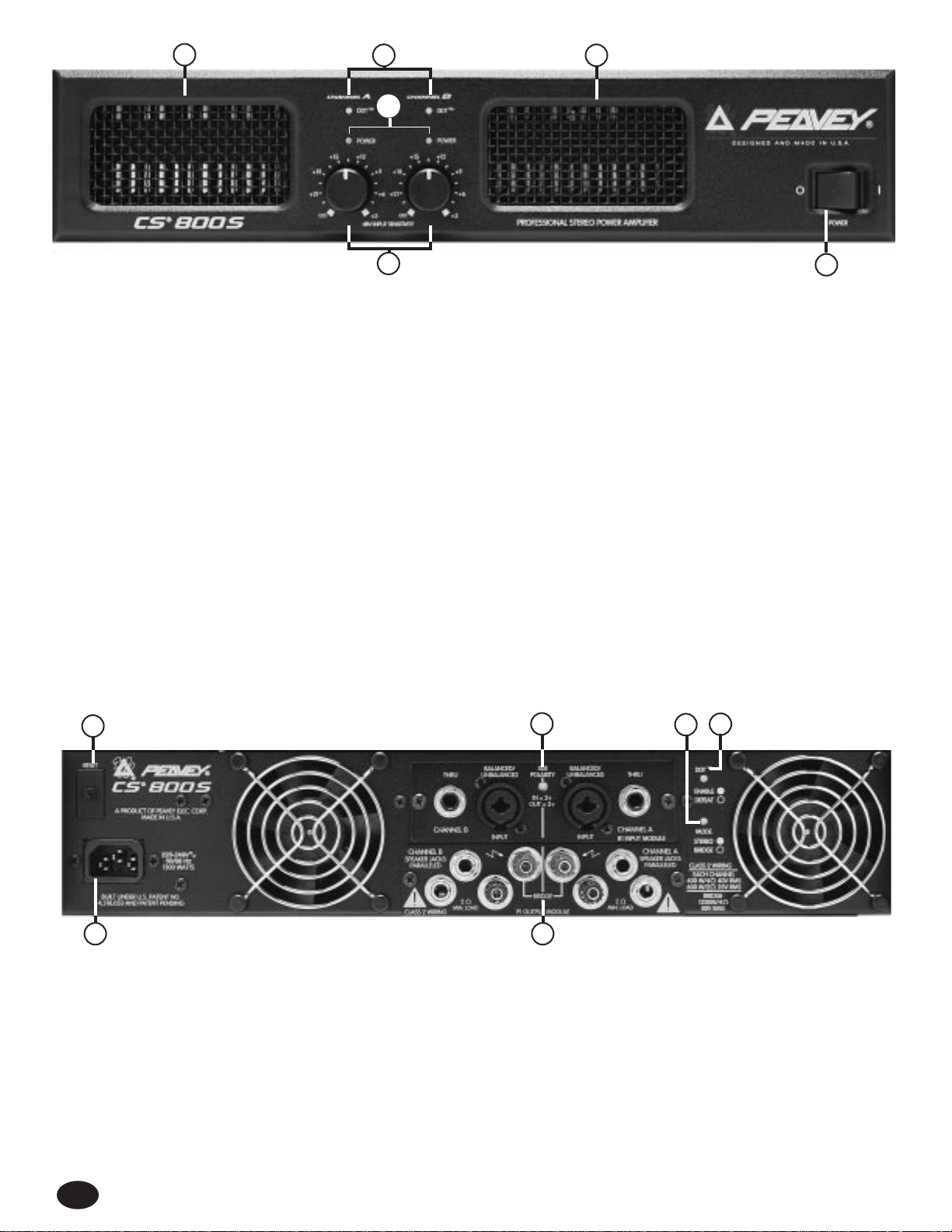
FRONT PANEL
DDT
™
ACTIVE LED (1)
Illuminates when DDT™Compression is taking place.With the ENABLE/DEFEAT switch in the DEFEAT position, the LED indicates
when clipping distortion is occurring.
POWER LED (2)
Illuminates when AC power is being supplied to the amp and the associated channel is operational.Illumination is delayed slightly
during the power-up cycle due to the transient suppression/thermal fault circuitry. If either channel experiences fault conditions or
exceeds the safe operating temperature limits, then that channel will shut down and the associated power LED will go out indicating
such conditions exist. Also, whenever the BRIDGE mode is selected, the power LED on channel B is defeated (OFF), just as if there
were a fault condition on channel B.This provides a positive indication that the CS 800S is in bridge mode.
INPUT SENSITIVITY (3)
Maximum power amplifier input gain (minimum sensitivity) is achieved at the full clockwise setting.This setting yields maximum
mixer/system headroom. A setting of less than full clockwise will yield lower system noise at the expense of headroom. Calibration
indicates sensitivity in dBV necessary to attain the full output power rating.
POWER SWITCH (4)
Depress to “on” position to power up unit.
AIR EXHAUST PORT (5)
This is where the hot air from the heat sinks exhaust from the amplifier. Any restriction or blockage could cause excessive operation
temperatures and the unit could shut down!
REAR PANEL
CIRCUIT BREAKER (6)
The CS®800S uses a circuit breaker in place of the main fuse.This breaker is provided to limit the current to the digital power supply
and thereby protect it from overheating and possible destr uction due to fault conditions in the amplifier.The trip current value has
been carefully chosen to allow continuous power output perfor mance while still providing adequate protection for the power supply.
Normally, this breaker should not trip unless there is a fault in the amplifier circuitry that draws excessive mains current. However,
abnormal conditions such as a shor t circuit on either or both channels or continuous operation at overload or clipping, especially into
2 ohm load, will cause the breaker to trip.If this occurs, simply reset the breaker and correct the cause of the overload. When tripped,
the button on the breaker will be outward nearly 1/2", and can be reset by pushing inward. A nor mal reset button length is about 1/4".
If this “thermal” type breaker does trip, then simply pushing the button back in will reset it after waiting a brief period of time to allow it
to cool. If the breaker trips instantly when you attempt to reset it, the unit should be taken to a qualified service center for repair.
5
4
1 5
3
4
6
7
15
10
9
8
2
IEC MAINS POWER CONNECTOR (7)
The CS®800S is fitted with a universal IEC connector. Into this connector one should always insert a heavy duty #14 AWG 3
conductor line cord with a conventional AC plug with a ground pin. This line cord should be connected to an independent
mains circuit capable of supporting at least 15 amps continuously or greater.This is particular ly critical for sustained high
power applications. If the socket used does not have a ground pin, a suitable ground lift adapter should be used and the third wire
grounded properly. Never break off the ground pin on the 3 conductor line cord.The use of extension cords should be avoided, but if
necessary, always use a three-wire type with at least a #14 AWG wire size.The use of lighter wire will severely limit the power
capability of this amplifier.Always use a qualified electrician to install any necessary electr ical equipment. To prevent the risk of shock
or fire hazard, always be sure that the amplifier is properly grounded.
DDT™SWITCH (8)
This switch is used to either ENABLE or DEFEAT the DDT™compressor.
MODE SWITCH (9)
This switch is used to select either STEREO or
BRIDGE mode of operation.
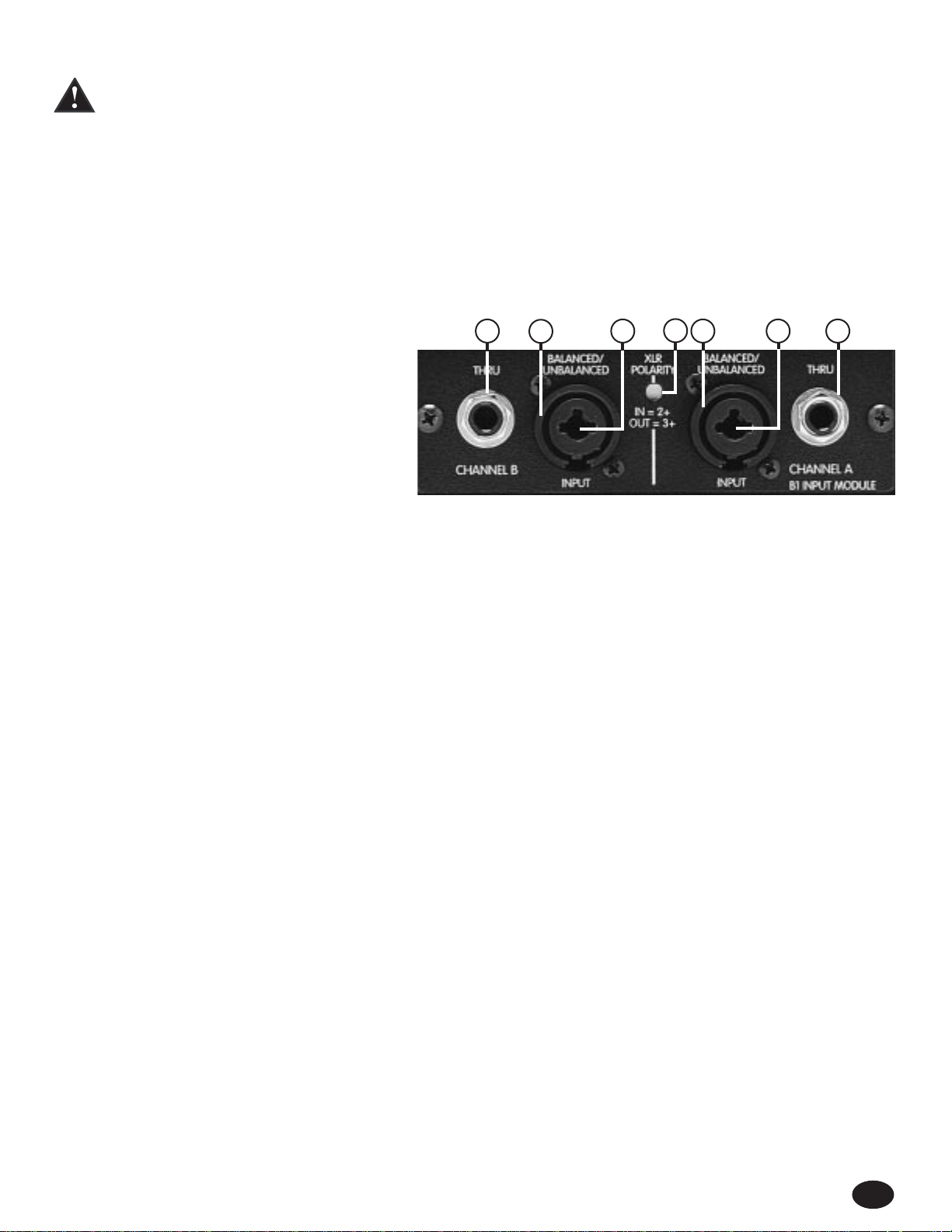
THE B1 INPUT MODULE (10)
The standard input module shipped with each amplifier
is called the B1 MODULE. It offers both XLR electronic
balanced and phone jack quasi-balanced inputs for
each channel using Neutrik's new “combo” connector
to save panel space.
The female XLR inputs (11)
are connected to dual OP AMP circuitry which offers very low noise and extremely high common mode rejection ratio to minimize
outside interference!
The female 1/4" phone jack input (12)
in the center of the “combo” connectors are also connected to a unique “quasibalanced” input circuitr y.When used, these 1/4" jacks are not “chassis grounded” but connected to ground through a relatively low
impedance circuit which is part of a “ground loop” elimination circuitry associated with the input.This feature will normally allow “hum
free” operation when relatively shor t 1/4" cable patches are made to this input from various outputs on this amp and other equipment
that share the same rack with this amp.This “quasi-balanced” circuit is “automatic”, and is virtually invisible in normal usage. It cannot
be defeated.
Between the two XLR connectors is a
recessed switch (13)
which allows the user to select the desired polarity (phase) of the
XLR inputs.This switch is a push-push type and a small diameter
“
tool” is required to select the desired position. Set to the out
(default) position, the polarity is pin #3 positive, pin #2 negative, and pin #1 ground. This is the polarity found on most Peavey power
amplifiers. Although this is not the world "standard" (IEC) polarity, it was chosen by Peavey more than 20 years ago, and thus we offer
this polarity to be consistent with products both past and present. If this amplifier is used with other competitive products which use
the IEC standard polarity, then the “in” position of switch (13) should be selected yielding pin #2 positive, pin #3 negative, and pin #1
ground. As with any electronic gear, polarity (phasing) is important because the loudspeaker enclosures associated with this power
amplifier must be in phase with any other loudspeaker enclosures associated with other power amps. If one loudspeaker system were
to “push” while the other “pulls”, then a serious sound “cancellation” could result. Changing the setting of the polarity switch has the
same effect as reversing the polar ity of the loudspeaker connections at the output.
Each channel also has a
female phone jack (14)
labeled “thru”.This jack offers a very flexible patching capability.When the
XLR input connectors (11) are used, then this “thru” jack is the output of the electronic balanced input circuitry, and as such can be
used as a “line out” to connect to the other input jack on this amplifier or other amps in the same rack.Thus, one balanced mixer feed
can be connected to the amp via the XLR connector and then further distributed locally via the “thru” jack. Alternatively, when the 1/4"
phone jack input (12) is used as the input, the “thru” jack becomes a “bridged” input to it (similar to a Y-cord), again allowing this input
signal to be patched to the other input jack on this amplifier or other amps in the system.
Additional input modules are available from your author ized Peavey Dealer. Details of these modules and the installation instructions
can be secured from this source.
5
14
11
12
13
11 12 14
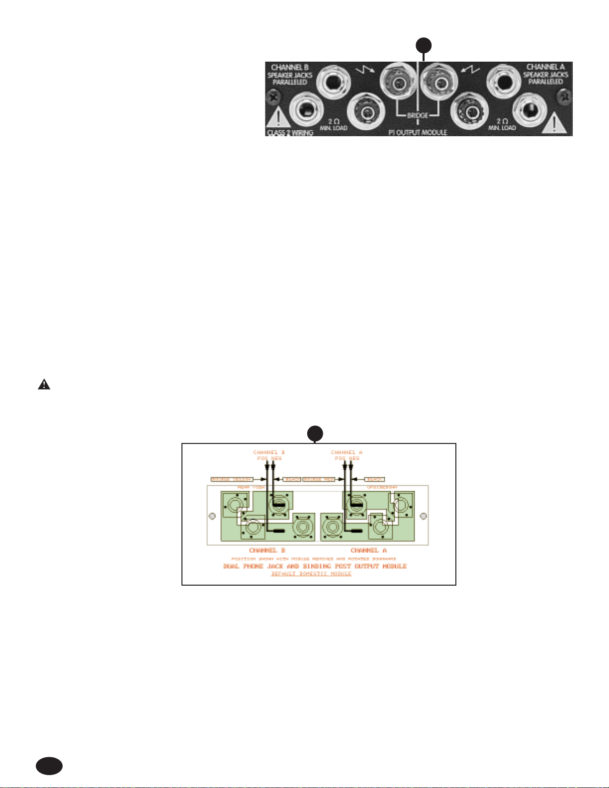
THE P1 OUTPUT MODULE (15)
The standard output module shipped with each
amplifier is called the P1 MODULE. It offers both dual
1/4" jacks and 5-way binding post speaker outputs for
each channel. For each channel, the outputs are in
parallel, hence the speaker connection cables can be
terminated with 1/4" phone plugs, or banana plugs or
stripped wires for use in the binding post terminals.
For sustained high power applications, the use of the
binding post terminals are recommended; however, care must be exercised to assure the correct speaker phasing.The red binding
posts are the signal outputs from each channel, and the black binding posts are chassis ground.The red binding post should be
connected to the positive inputs of the associated loudspeakers.For bridge mode operation, only the red binding posts are used, and
the associated loudspeaker load is connected between the two red binding posts.The red binding post associated with channel A
should be considered the positive output for the system and thus should be connected to the positive input of the associated
loudspeaker system.
Regardless of what connections are used, the minimum parallel speaker load should always be limited to 2 ohms per channel or 4
ohms bridge mode for any application. Operation at loads of 4 ohms per channel or 8 ohms bridge mode is more desirable for
sustained operation applications due to the fact that the amplifier will run much cooler at this loading. Operation above 4 ohms per
channel and even open circuit conditions can always be considered safe;however, sustained operation at loads below 2 ohms could
result in temporary amplifier shut down due to the thermal limits fault circuitry.
THE P1 OUTPUT MODULE REAR VIEW (16)
This diagram shows the wiring for the P1 MODULE.Note that the module itself is upside down.This is the desired position when
re-connecting this and any other module. Once the correct connections to the 1/4" spades are made, then the module itself can be
rotated upward and inserted into the rear panel of the CS-800S, and the panel screws replaced.
WARNING: Never operate the CS
®
800S with either the output or input modules removed.Operating in this manner will allow the
air flow from the fans to escape from these openings instead of flowing through the power amp and power supply components,
and thereby not provide adequate cooling for these components.
Following are several other module rear views of a different module and the various wiring schemes.The diagram above and the ones
following are provided so that these modules can be correctly wired.Always double-check the wiring. A miswired module can cause
severe audio problems, and in the worst case, can cause loudspeaker degradation and failure.In all cases, the color-coded wires are
indicated.The double red and yellow wires are the power amp outputs and are not interchangeable.The black wires are the power
amp ground connections and are interchangeable.
6
15
16
THE S2 OUTPUT MODULE
The S2 output module offers dual Speakon®Quick
Connectors and a unique patching capability to
wire these connectors to meet the particular application.The Speakon
®
is a four-wire connector with
the connections labeled as 1+, 1-, 2+ and 2-.
Depending upon the loudspeaker needs, these
connections can be used in various ways.
NOTE:
Consult your loudspeaker specifications to determine the wiring configuration
(mode) that will best suit your system.
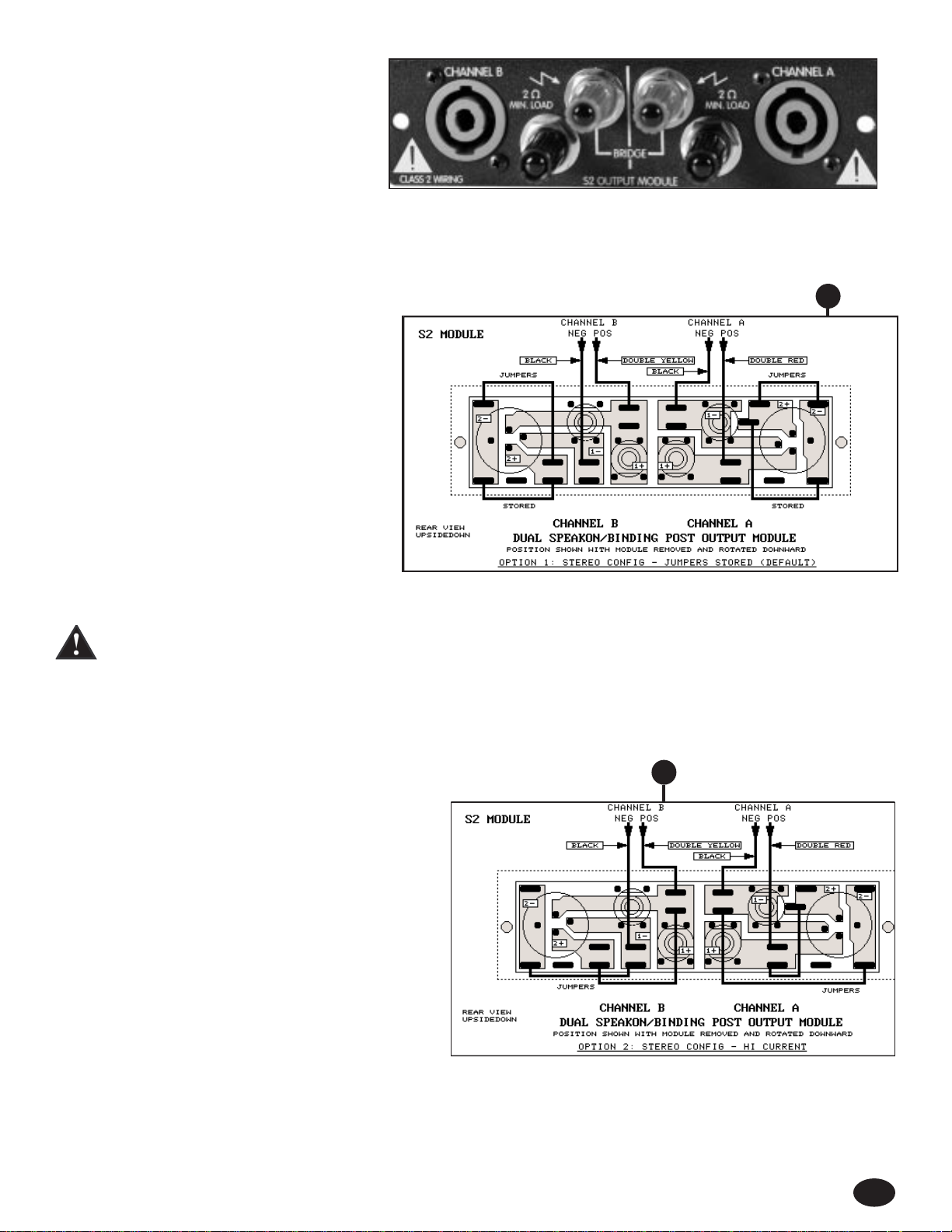
THE S2 OUTPUT MODULE REAR VIEW — STANDARD STEREO MODE (17)
This Speakon®wiring arrangement shown below is
as follows: 1+ as the channel signal output and 1- as
the channel chassis ground.This is the de facto
standard for most low-to-medium power loudspeaker
systems.This wiring allows one enclosure to be
connected to Channel A and one enclosure to be
connected to Channel B.The 2+ and 2- connections
are not used in this application. Please notice that
the binding posts on the S2 module also use the
1+ and 1- wiring arrangement.The channel A red
and black binding posts are always connected to the
channel A Speakon 1+ and 1- respectively. Similar ly,
the channel B red and black binding posts are
always connected to the channel B Speakon 1+
and 1- respectively.
WARNING:The S2 module is shipped with four jumpers plugged in a “storage” configuration across the nor mally unused 2+ and 2-
Speakon pins.These jumpers are used in other modes of operation following.This “storage” configuration could cause a
shorting problem if a par ticular loudspeaker system’s Speakon connectors are wired in the high current configuration outlined next (1+ and 2+ are connected and 1- and 2- are connected). In this case, we recommend that you remove the
jumpers.
THE S2 OUTPUT MODULE REAR VIEW - HIGH CURRENT STEREO MODE (18)
Many high power loudspeaker systems use the full capability
of the Speakon connector by paralleling 1+ and 2+, and
paralleling 1- and 2-.This wir ing improves the current
handling capability of the system and reduces losses. Many
subs with Speakons are wired this way.The S2 module can
be rewired to this configuration using the supplied jumpers
on the rear of the module. Normally, four jumpers are
plugged into a “storage” configuration to prevent losing
them. In this case, one jumper is connected between 1+
and 2+ and another jumper is connected between 1- and
2- for each channel.This is a total of four jumpers.The
following diagram shows the new wiring of the jumpers.
Notice for this mode, the binding post can still be used as
normal outputs for both channels.
7
17
18
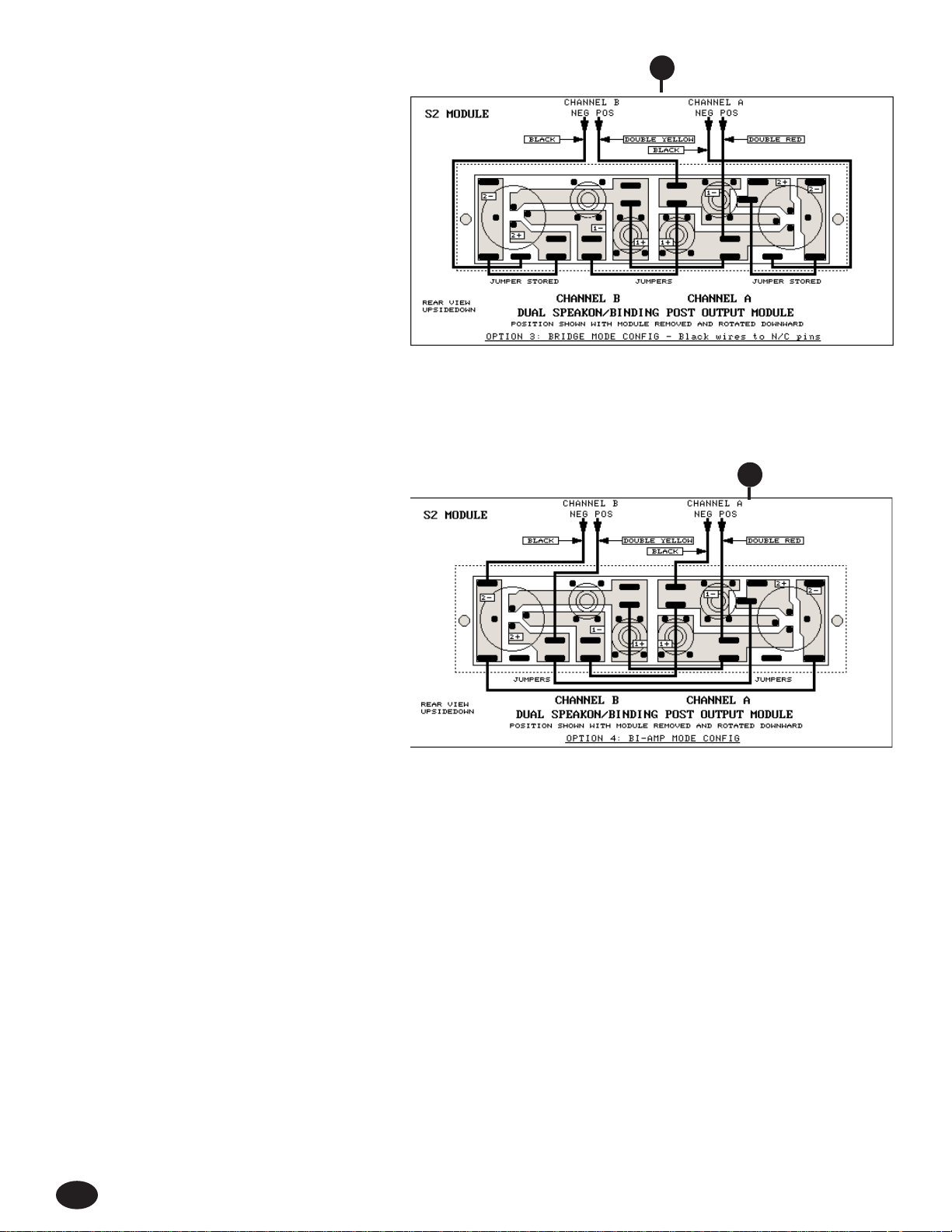
THE S2 OUTPUT MODULE REAR VIEW - BRIDGE MODE (19)
The following wiring allows the Speakons to be the
bridge outputs with both in parallel. Such an arrangement permits two 8 ohm enclosures to be connected
in parallel to the CS-S amp in Bridge Mode. In this
case, the wiring is as follows: 1+ on both connectors
wired to Channel A signal output; 1- on both connectors wired to Channel B signal output; 2+ and 2- on
both connectors not used.The Channel A and B
chassis ground wires are not used (and are plugged
into isolated floating terminals.) This wiring requires
one jumper per channel for a total of two; the other
two are “stored.” Please note for this wiring, both red
binding posts are now connected to the channel A
output, and both black binding posts are now
connected to channel B output. Consequently, to connect additional speakers in bridge mode one must use a red and black binding
post pair rather than connecting across both red binding posts as in the default arrangement.
THE S2 OUTPUT MODULE REAR VIEW - BIAMP MODE (20)
The final wiring arrangement is a natural progression
of the Speakon®capability with its four wire connections. Biamping is often the preferred configuration for
many sound reinforcement systems.The Speakon
pins used in the typical biamped speaker enclosure
are: 1+ = LOW+; 1- = LOW-; 2+ = HI+; 2- = HI-. This
is also a “standard.” In this case, two biamped wired
loudspeaker enclosures can be connected to a CS-S
amp via the two Speakon connectors.First, the CS-S
amp must be configured for biamp with each channel
signal supplied from a suitable crossover, and most
importantly, the configuration is: Channel A as the
“lows” and Channel B as the “highs.” For this mode
then, the wiring is: 1+ on both connectors wired to
Channel A signal output; 1- on both connectors wired
to Channel A chassis ground wire; 2+ on both connectors wired to Channel B signal output; 2- on both connectors wired to Channel B
chassis ground wire.This arrangement again requires two jumpers per channel for a total of four. Always check the diagram and wire
the module with care. For this wiring, both red binding posts are now connected to the channel A output, and both black binding posts
are now connected to chassis ground.Thus, both binding post red/black pairs are the biamped low output, and can be used to drive
additional sub enclosures, if desired.
INSTALLATION AND CONNECTION
The Peavey CS®800S commercial series power amplifier is designed for durability in commercial installations and the quality of
performance required in studio and home applications.The unit is a standard rack-mount configuration, 3 1/2" high and is cooled by
two variable-speed internal fans.All the input and output connections are on the back panel. The front panel contains LED indicators
for power and DDT activation, detented/calibrated sensitivity controls, and a mains power switch.
INDUSTRIAL AND COMMERCIAL INSTALLATIONS
For commercial and other installations where sustained high powered operation is required, the CS®800S should be mounted in a
standard EIA 19" rack. It is not necessary to leave rack space between each amplifier in the stack, since the fan pulls air in from the
rear and exhausts the hot air out the front. An adequate source of cool air must be provided for the amplifier when rack-mounted.The
internal fans must have a source of air that is not preheated by other equipment. If cool, the amplifier will star t up in low-speed fan
operation, and will normally stay at low-speed operation unless sustained high power operating levels occur. As the amplifier heat
sinks heat up the automatic thermal sensing circuitry will increase the fan speed. Depending upon signal conditions and amp loading,
the fan speed may increase to a maximum value, or it may decrease to a minimum value.This situation is quite normal.
8
19
20

Inadequate cooling due to preheated air, a reduction of air flow caused by blockage of the amplifier's inlet/outlet ports, or severely
overloading the amp may cause the amplifier's thermal sensing system to temporarily shut down that particular channel.This will be
indicated by the channel power LED on the front panel ceasing to illuminate.Depending upon available cooling air, operation will be
restored to that channel relatively quickly, and the power LED will then be illuminated. Corrective action should be taken to determine
the cause of the thermal shutdown. If the amplifier is not severely overloaded or shorted, and air flow is normal in and out of the unit,
steps should be taken to provide a cooler environment for all the amplifiers. As a general rule, electronic equipment in a cooler
environment will have a longer and more useful service life.
STUDIO AND HOME INSTALLATION
In most low- to medium-power applications, the CS 800S can be mounted in any configuration. It is desirable that, if at all possible,
the unit be located at the top of an equipment stack.This will prevent possible overheating of any sensitive equipment by the hot air
rising from the power amplifier.As a general rule, most home and studio requirements will never cause maximum high speed fan
operation. If it does, however, this may indicate that you have not taken the necessary steps to provide adequate cooling. Remember,
closed up in a cabinet, the CS 800S will have severe cooling problems, even at low power levels. Again, inadvertent shor t circuit or
sustained overloaded usage could also cause temporary thermal shutdown. Most home wir ing and electrical circuits are only 15
amps.Two CS 800S amplifiers could cause a power panel 15 amp circuit breaker to trip if a severe overload occurs.
BRIDGE MODE
The bridge mode on stereo amplifiers is often misunderstood as to its actual operation and usage. In basic terms, when a twochannel amplifier is operated in bridge mode, it is converted into a single channel unit with a power rating equal to the sum of both
channels
’
power ratings, at a load rating of twice that of the single channel rating.In this case, the CS 800S is rated at 600 W RMS
per channel into 2 ohms.The bridge mode ratings are 1,200 W RMS into 4 ohms (minimum load).The br idge mode operation is
accomplished by placing the mode switch into the bridge position, connecting the load between the red binding posts of each
channel, and then using channel A as the input channel. All channel B input functions are defeated.
Another application for bridge mode operation is to drive sound distribution systems in very large public address applications.In this
mode, the CS®800X power amplifier can actually drive 70-volt systems directly without using expensive matching transformers.The
real advantage of such an approach is primarily cost. 70-volt distribution systems are very common in domestic applications where
large numbers of relatively small loudspeakers are used for background music and paging. Such systems require the use of 70-volt
transformers at each loudspeaker. Another common use for the bridge mode is in subwoofer applications where very high output
power levels are required to reproduce extremely low frequencies. Such enclosures usually contain two or four loudspeakers to
handle the high power levels involved. For bridge mode usage, the enclosure impedance must be 4 or 8 ohms. Never below 4 ohms!
Also make sure the enclosure can handle 1,200 watts reliably.
DDT
™
Peavey’s patented DDT™compression system enables the sound man to maximize the performance of the amplifier/speaker
combination by preventing the power amp from running out of headroom (clipping). This compression system is activated by a unique
circuit that senses signal conditions that might overload the amplifier and reduce the amplifier's gain when clipping is imminent.The
threshold of compression is clipping itself and no specific threshold control is used.This technique effectively utilizes every precious
watt available for the power amplifier to reproduce the signal while at the same time minimizes clipping and distortion, and thus
significantly reduces the potential of loudspeaker degradation and damage.The DDT system is an automatic, hands-off approach to
the problem of power amplifier clipping.
Since the CS 800S power amplifier uses a circuit breaker for over-current protection, the DDT compression system plays even a more
important role in the continuous performance by preventing each channel from clipping and over loading. Continuous operation at
clipping can cause the circuit breaker to trip, but with the DDT activated this problem is minimized. For this reason, you should always
have the DDT compression system enabled.
9

10
OUTPUT POWER: (Typical value, 120 V AC, 60 Hz)
Stereo mode, both channels driven
2 ohms, 1 kHz, 1% THD, 600 W RMS per chan
4 ohms, 1 kHz, 1% THD, 420 W RMS per chan
8 ohms, 1 kHz, 1% THD, 260 W RMS per chan
Bridge mode, mono:
4 ohms, 1 kHz, 1% THD, 1,200 WRMS
8 ohms, 1 kHz, 1% THD, 840 WRMS
RATED OUTPUT POWER: (120 V AC, 60 Hz)
Stereo mode, both channels driven
4 ohms, 10 Hz to 20 kHz, 0.03% THD, 400 W
RMS per channel
8 ohms, 10 Hz to 20 kHz, 0.02% THD, 240 W
RMS per chan
POWER BANDWIDTH:
Stereo mode, both channels driven
@ rated power, 4 ohms, <0.1% THD - 10 Hz
to 50 kHz
TOTAL HARMONIC DISTORTION:
Stereo mode, both channels driven
10 Hz to 20 kHz, 4 ohm rated output, Less
than 0.03%
HUM and NOISE:
Stereo mode, both channels driven
Below rated output power, 4 ohms, Greater than
100 dB (30 kHz BW, unweighted)
DAMPING FACTOR:
Stereo mode, both channels driven
4 ohms, 100 Hz, Greater than 1,000
4 ohms, 10 kHz, Greater than 400
INPUT SENSITIVITY and IMPEDANCE:
Input attenuator set @ FCW @ rated output power,
4 ohms, 1.4 V RMS (+3 dBV) - 20k ohms
unbalanced
CHANNEL VOLTAGE GAIN:
Input attenuator set @ FCW
Stereo mode, 4 ohms, 1 kHz, 29 dB
Bridge mode, 8 ohms, 1 kHz, 35 dB
FREQUENCY RESPONSE:
Stereo mode, both channels driven
+0, -1 dB, 1 W RMS, 4 ohms, 3 Hz to 60 kHz
+0, -0.1 dB @ rated output, 4 ohms, 20 Hz to
20 kHz
SLEW RATE:
Stereo mode, each channel - Greater than 40 V/uS
Bridge mode, mono, Greater than 80 V/uS
SQUARE WAVE RESPONSE:
Stereo mode, 4 ohms, 80 V P-P output
100 Hz waveform tilt, Less than 5 volts
10 KHz waveform rise-time, Less than 2 uS (0%
over-shoot)
PHASE DISTORTION:
Stereo mode, 4 ohms @ rated power
20 Hz leading waveform - Less than 6 degrees
20 KHz lagging waveform - Less than 15 degrees
POWER CONSUMPTION:
Stereo mode, both channels driven
@ rated output power, 4 ohms, 10 A @ 120 V AC
COOLING SYSTEM:
Dual continuously variable speed DC fans
DDT
™
COMPRESSION SYSTEM:
Automatic, switchable with LED indicator
DIMENSIONS and WEIGHT:
Height: 3.50" (8.9 cm)
Width: 19" (48.3 cm)
Depth: 17" (43.2 cm)
Weight: 23 lbs (10.5 kg)
Specifications subject to change without notice.
CS®800S SPECIFICATIONS

MANUAL DEL PROPIETARIO DEL AMPLIFICADOR DE POTENCIA CS®800S
Lo felicitamos por la compra del nuevo amplificador de potencia estereofónico CS
®
800S. Esta versión, la más reciente y avanzada
existente, utiliza la última palabra en tecnología de conmutación de estado sólido para brindar alta fidelidad y un sólido rendimiento
en una unidad que ocupa dos espacios de rack y pesa menos de 10,4 kg. Este nuevo diseño retiene la capacidad de rendimiento
extendido del modelo CS
®
800X anterior, con su impresionante potencia de salida sobre 2
Ω
. Sin embargo, mantiene las
especificaciones para 4 y 8
Ω
anteriores con excelentes características normalizadas de ancho de banda de potencia,
velocidad de variación rápida y distorsión. El nuevo diseño “S” refleja también una mejora considerable en las especificaciones
del factor de amortiguamiento. A continuación se indican las especificaciones del amplificador CS 800S:
• 420 Wef (potencia eficaz) sobre 4
Ω
y 600 Wef sobre 2 Ω(por canal)
• 840 Wef sobre 8
Ω
y 1200 Wef sobre 4 Ω(modo de puente)
• Compresión DDT
™
con indicadores de LED e interruptor de desactivación
• Velocidad de variación rápida: 40 V/µs, en modo estereofónico, por canal
• Respuesta en frecuencia: 10 Hz a 50 kHz sobre 4
Ω
a la potencia nominal
• Distorsión armónica total: menos del 0,03% a la potencia nominal
• Zumbido y ruido: 100 dB por debajo de la potencia nominal, sin ponderación
• Factor de amortiguamiento: mayor que 1000 sobre 4
Ω
a 100 Hz, por canal
El pesado transformador se reemplaza por una fuente de alimentación de conmutación extremadamente confiable, que utiliza la
probada topología de medio puente para proporcionar 1700 W de potencia pico gracias a un eficiente diseño con IGBT (transistores
bipolares de compuerta aislada). La fuente cuenta con un sistema de monitoreo térmico con limitación de corriente proporcional, que
evita el apagado total a temperaturas de operación extremas. El nuevo amplificador CS 800S retiene el sistema de compresión
patentado DDT
™
, que elimina prácticamente cualquier posibilidad de distorsión por sobrecarga. El nuevo diseño del panel posterior
incluye ahora módulos enchufables para ambas entradas y salidas, para ofrecer así características de interconexión y flexibles varias
opciones de conectores. Cuando se requiere, dos ventiladores de CC de velocidad variable proporcionan una potente capacidad de
enfriamiento.
CARACTERISTICAS DEL AMPLIFICADOR
• Altura de dos racks, menos de 43,2 cm de profundidad
• Menos de 10,4 kg, con fuente de alimentación de conmutación
• Entradas modulares enchufables
• Enchufe hembra doble XLR (balanceado)/fonográfico (desbalanceado) con salida pasante en cada canal
• Módulo separador de frecuencias universal de tres vías
• Salidas modulares enchufables
• Enchufe hembra doble fonográfico y bornes de 5 vías por canal
• Conexión rápida SPEAKON
®
con selección de terminales interconectables
• Construcción modular
• Módulos de canales y fuente de alimentación reemplazables
• Período transitorio de encendido de alimentación eléctrica muy breve
• Dos ventiladores de CC de velocidad variable, para niveles de ruido más bajos
• Control de atenuador calibrado/por pasos para cada canal
• LED de activación de DDT y encendido en cada canal
• Interruptores de DDT y modo de puente embutidos en el panel posterior
• Conector de alimentación eléctrica IEC
FUENTE DE ALIMENTACION DIGITAL
• Ultraconfiable y robusta
• Con la probada topología de medio puente, para menos componentes
• 1700 W de potencia pico, sobredimendionado en 25%
• Diseño IGBT de alto rendimiento
• Liviano y económico
• Disipador de aluminio grande, para mayor estabilidad térmica
• Sistema de monitoreo térmico con limitación automática de corriente; el amplificador no se apaga excepto
en caso de falla
ESPANOL
11
÷

• Eficaz diseño de filtro de bajo costo, con baja EMI (interferencia electromagnética) por conducción
• Totalmente operacional hasta con 85 VCA de suministro de la red (voltaje nominal de 110 V) y 170 VCA
(voltaje nominal de 220 V)
Sin duda comprobará que nuestro CS 800S no es simplemente otro amplificador de potencia, sino el mejor amplificador que pudo
haber comprado.Por favor lea cuidadosamente este manual del propietario. Le ayudará a usar más efectivamente este interesante
producto.
PANEL FRONTAL
LED DE DDT
™
ACTIVO (1)
Se enciende cuando tiene lugar la compresión DDT. Con el interr uptor ENABLE/DEFEAT (activación/desactivación) del panel
posterior en la posición DEFEAT (desactivación), este LED indica si se produce distorsión por recorte.
LED DE ENCENDIDO (2)
Se enciende cuando se suministra corriente alterna al amplificador y el canal asociado está en funcionamiento. La iluminación del
LED se retarda ligeramente durante el ciclo de encendido, debido al circuito de supresión de transitorios/falla térmica. Si algún canal
experimenta una condición de falla o excede los límites de temperatura de operación segura, el canal se desactiva y el indicador LED
de encendido asociado se apaga para indicar que existen estas condiciones.Asimismo, cuando se selecciona el modo BRIDGE
(puente), el LED de encendido del canal B se apaga, como si hubiera una condición de falla en dicho canal.Esto proporciona una
indicación positiva de que el amplificador CS 800S está en el modo de puente.
SENSIBILIDAD DE ENTRADA (3)
La máxima ganancia de entrada del amplificador de potencia (sensibilidad mínima) se obtiene en la posición extrema de giro a la
derecha. Este ajuste proporciona máxima tolerancia de amplitud para el mezclador y el sistema. Una posición menor que la extrema
derecha producirá menos ruido del sistema a expensas de la tolerancia de amplitud. La calibración indica la sensibilidad en dBV
necesaria para obtener plena potencia nominal de salida.
INTERRUPTOR DE ENCENDIDO (4)
Para encender la unidad, oprima este interruptor hacia la posición de conexión.
ORIFICIO DE ESCAPE DE AIRE (5)
Es el lugar de salida del amplificador para el aire caliente de los disipadores. Cualquier restricción o bloqueo puede causar una
temperatura de operación excesiva y el subsiguiente apagado de la unidad.
PANEL POSTERIOR
CORTACIRCUITOS (6)
El amplificador CS®800S usa un cortacircuitos en lugar del fusible principal. La función del cortacircuitos es limitar la corr iente que
absorbe la fuente de alimentación y protegerla así del recalentamiento y la posible destrucción en caso de falla del amplificador. El
valor de corriente de disparo se eligió cuidadosamente para permitir el funcionamiento continuo con potencia de salida y
proporcionar protección adecuada para la fuente. Normalmente, este cor tacircuitos no debería dispararse, a menos que exista una
falla en el circuito del amplificador que produzca un consumo excesivo de corr iente de alimentación. No obstante, las condiciones
anormales tales como un cor tocircuito en uno o ambos canales, la operación continua con sobrecarga o distorsión por recorte,
especialmente sobre carga de 2
Ω
, pueden causar el disparo del cortacircuitos. Si esto ocurre, restablezca simplemente el
cortacircuitos y corrija la causa de la sobrecarga. Cuando se dispara, el botón del cortacircuitos unos 13 mm y puede ser
restablecido oprimiéndolo hacia adentro.La longitud del botón restablecido es normalmente de unos 6 mm. Si el cor tacircuitos
de tipo “térmico” se dispara, se restablece con sólo oprimir el botón, después de un breve período de espera para permitir que
se enfríe. Si el cor tacircuitos se dispara instantáneamente cuando intenta restablecerlo, lleve la unidad a un centro de servicio
calificado para su reparación.
CONECTOR DE ALIMENTACION IEC (7)
El amplificador CS 800S está dotado de un conector IEC universal. En este conector debe insertarse siempre un cordón de
alimentación de tres conductores calibre AWG Nº 14 de servicio pesado con un enchufe convencional para CA con terminal
de conexión a tierra.Este cordón se debe conectar a un circuito independiente de la red de suministro capaz de soportar
continuamente por lo menos 15 A o más. Esto resulta particular mente crítico para las aplicaciones de alta potencia sostenida. Si el
receptáculo usado no tiene terminal de conexión a tierra, debe utilizarse un adaptador apropiado para eliminación del circuito de
tierra y el tercer conductor debe conectarse adecuadamente a tierra. Nunca corte el ter minal de conexión a tierra del cordón de tres
conductores. Debe evitarse el uso de cables de prolongación. En caso de ser necesario, use siempre un cable de tipo de tres
conductores de tamaño AWG Nº 14.Los conductores más delgados limitan ser iamente la capacidad de potencia del amplificador.
Emplee siempre electricistas calificados para instalar todos los equipos eléctricos necesarios. Para evitar los riesgos de descarga
eléctrica o incendio, asegúrese siempre de que el amplificador esté correctamente conectado a tierra.
12

INTERRUPTOR DE MODO DDT™(8)
Este interruptor se usa para activar (ENABLE) o anular (DEFEAT) el compresor DDT™.
INTERRUPTOR DE MODO (9)
Este interruptor se usa para seleccionar los modos de operación STEREO (estéreo) o BRIDGE (puente).
MODULO DE ENTRADA B1 (10)
El módulo de entrada estándar que se envía junto con el amplificador se denomina MODULO B1. Cada canal cuenta con entradas
XLR balanceadas electrónicamente y cuasibalanceadas con enchufe hembra fonográfico.Para ahorrar espacio en el panel, la
entradas utilizan el nuevo conector “combinado” Neutrik.
LAS ENTRADAS XLR HEMBRA (11)
se conectan al circuito del amplificador operacional doble que ofrece muy bajo ruido y una relación de rechazo de modo común
extremadamente alta para minimizar la interferencia exterior.
LAS ENTRADAS DE ENCHUFE HEMBRA FONOGRÁFICO DE 1⁄4" (12) del centro de los conectores “combinados” se conectan
también a un circuito de entrada “cuasibalanceado” exclusivo. Cuando se usan, estos enchufes hembra de 1⁄4" no se “conectan a
tierra” en el chasis sino mediante un circuito de relativamente baja impedancia que forma par te del sistema de eliminación del
“circuito de tierra” asociado con la entrada. Esto permite una operación “libre de zumbido”, siempre que se efectúen interconexiones
relativamente cortas con cables de 1⁄4" desde diversas salidas del amplificador y los demás equipos que comparten el mismo rack.
Este circuito “cuasibalanceado” es “automático” y prácticamente “indetectable” durante el uso normal. No puede anularse.
Entre los dos conectores XLR existe un interruptor embutido (13) que permite al usuario seleccionar la polaridad (fase) deseada de
las entradas XLR. Este interruptor es del tipo pulsador y se requiere una “herramienta” de diámetro pequeño para seleccionar la
posición elegida. En la posición por defecto (hacia afuera), la polaridad es terminal Nº 3, positivo; Nº 2, negativo; y
Nº 1, tierra. Esta es la polaridad más común de los amplificadores Peavey. Si bien ésta no es la polaridad “estándar” (IEC) a nivel
mundial, es la que Peavey eligió hace más de 20 años y la ofrecemos por cuestiones de coherencia con los productos antiguos y
actuales. Si este amplificador se usa con productos de la competencia de polaridad IEC estándar, debe seleccionarse la posición del
interruptor (13) hacia adentro, para la cual el terminal Nº 2 es positivo; el Nº 3, negativo; y el Nº 1, tierra. Como en cualquier aparato
electrónico, la polaridad (relación de fases) es importante porque las cajas de altavoces asociadas con este amplificador de potencia
deben estar en fase con otras cajas conectadas a otros amplificadores.Si un sistema de altavoces “empuja” mientras el otro “tira”,
puede producirse un grave efecto de “cancelación”. El cambio de la posición del interr uptor de polaridad tiene el mismo efecto de la
inversión de las conexiones del altavoz en la salida.
CADA CANAL CUENTA TAMBIÉN CON UN ENCHUFE HEMBRA FONOGRÁFICO (14) rotulado “thru” (pasante). Este enchufe
ofrece una capacidad de interconexión muy flexible. Cuando se usan los conectores de entrada XLR (1), este enchufe es la salida del
circuito de entrada balanceado electrónicamente y, como tal, se puede usar como “salida de línea” para conectar al otro enchufe
hembra de entrada de este amplificador o a otros amplificadores del mismo rack.De esta forma, una alimentación del mezclador
balanceado se puede conectar al amplificador con el conector XLR y distribuir ulteriormente en forma local mediante el enchufe
pasante. Como alternativa, cuando se usa como entrada el enchufe hembra fonográfico de 1⁄4" (12), el enchufe pasante se convier te
en una entrada “puenteada” (similar a un cordón Y), para per mitir nuevamente que esta señal de entrada sea interconectada a los
otros enchufes hembra del amplificador o desde otros amplificadores del sistema.
El distribuidor Peavey autorizado dispone de módulos de entrada adicionales. Pueden obtenerse en esta fuente los detalles de estos
módulos y las instrucciones de instalación.
MODULO DE SALIDA P1 (15)
El módulo de salida estándar despachado con cada amplificador se denomina MODULO P1.
Cuenta con salidas de altavoz dobles con enchufes hembra de 1⁄4" y bornes de 5 vías en cada canal. Por otra parte, las salidas de
cada canal están en paralelo y por lo tanto los cables de conexión de los altavoces se pueden terminar con clavijas fonográficas, de
tipo “banana” o cables con extremos desnudos para conectar a los bornes. Para aplicaciones de alta potencia sostenida, se
recomienda usar estos últimos terminales. No obstante, debe tenerse cuidado para asegurar la correcta relación de fase entre los
altavoces.Los bor nes rojos son las salidas de señal de cada canal y los negros la tierra del chasis. El bor ne rojo debe conectarse a
las entradas positivas de los altavoces asociados. Para operación en modo de puente, sólo se usan los bornes rojos y la carga de
altavoces asociados se conecta entre estos dos bornes. El borne rojo asociado con el canal A debe considerarse como la salida
positiva del sistema y por ello debe conectarse a la entrada positiva del sistema de altavoces asociado.
13

Independientemente del tipo de conexiones a usar, la carga mínima de los altavoces en paralelo debe limitarse siempre a 2 Ωpor
canal o 4
Ω
en el modo de puente para cualquier aplicación. En las aplicaciones de operación en forma sostenida, es preferible
operar con cargas de 4
Ω
por canal u 8 Ωen modo de puente, debido al hecho de que el amplificador funcionará mucho más frío
con estas cargas. La operación con más de 4
Ω
por canal y aun las condiciones de circuito abierto pueden siempre considerarse
seguras. En cambio, la operación en forma sostenida a cargas inferiores a 2
Ω
puede hacer que el amplificador se apague
temporalmente debido al circuito de falla por límites de temperatura del mismo.
VISTA POSTERIOR DEL MODULO DE SALIDA P1 (16)
El diagrama precedente muestra el cableado del MODULO P1.Obser ve que el módulo propiamente dicho está invertido. Esta es la
posición deseable cuando se reconecta éste y cualquier otro módulo.Una vez realizadas las conexiones correctas a los terminales
de horquilla de 1⁄4", el módulo se puede girar hacia arriba e insertar en el panel poster ior del amplificador 800S y colocar
nuevamente los tornillos del panel.
ADVERTENCIA: Nunca opere el amplificador CS 800S con los módulos de entrada o salida desmontados. Si se opera de esta
manera, se permitirá que el aire fluya desde los ventiladores para escapar por esas aberturas en lugar de circular por los
componentes del amplificador de potencia y la fuente de alimentación. En estas condiciones, el ventilador no proporciona un
enfriamiento adecuado de estos componentes.
Se muestran a continuación las vistas posteriores y los diagramas de cableado correspondientes a otros módulos.El diagrama
precedente y los que siguen se proporcionan a fin de que estos módulos se puedan cablear correctamente.Verifique siempre el
cableado dos veces.Un módulo mal cableado puede causar graves problemas de audio y, en el peor de los casos, provoca la
degradación del sonido y la falla de los altavoces. Se indican en todos los casos los códigos de colores de los cables. Los cables
dobles rojos y amarillos son las salidas del amplificador de potencia y no son intercambiables. Los cables negros son las conexiones
de tierra del amplificador y sí son intercambiables.
MÓDULO DE SALIDA S2
El módulo de salida S2 posee conectores rápidos Speakon®y una capacidad exclusiva de conexiones temporales para cablear estos
conectores y satisfacer los requisitos de las aplicaciones específicas.El conector Speakon
®
es de cuatro conductores y tiene las
conexiones marcadas: 1+, 1–, 2+ y 2–. Según las necesidades de los altavoces, estas conexiones se pueden utilizar de varias
formas. NOTA: Consulte las especificaciones de sus altavoces para determinar la configuración (modo) de cableado que mejor se
adecue a su sistema.
VISTA POSTERIOR DEL MÓDULO DE SALIDA S2 – MODO ESTEREOFÓNICO ESTÁNDAR (17)
Esta disposición de cableado del conector Speakon®, mostrada abajo, es como sigue:1+ como salida de la señal del canal y
1– como conexión a tierra de chasis del canal.Esta es la norma de hecho para la mayoría de los sistemas de altavoces de baja
a media potencia. Este cableado permite conectar un gabinete al Canal A y el otro gabinete al Canal B. En esta aplicación no se
utilizan las conexiones 2+ y 2–.Tenga a bien notar que los bor nes del módulo S2 también utilizan la disposición de cableado 1+ y
1–. Los bor nes rojo y negro del Canal A, siempre están conectados a 1+ y 1– del conector Speakon respectivamente. De la misma
manera, los bornes rojo y negro del canal B están siempre conectados a 1+ y 1– del conector Speakon del canal B respectivamente.
ADVERTENCIA: El módulo S2 se despacha con cuatro puentes enchufados, en una configuración de “almacenamiento”, sobre los
terminales 2+ y 2–, normalmente no utilizados. Estos puentes se utilizan en otros modos de operación que se describen más
adelante. Si los conectores Speakon de un sistema de altavoces determinado están cableados con la configuración de alta
corriente que se describe a continuación (con 1+ y 2+ conectados y 1– y 2– también conectados), esta configuración de
“almacenamiento” puede causar problemas de cor tocircuito. En ese caso, recomendamos sacar los puentes.
VIST APOSTERIOR DEL MÓDULO DE SALIDA S2 – MODO ESTEREOFÓNICO DE AL TA CORRIENTE (18)
Muchos sistemas de altavoces de potencia utilizan completamente las capacidades del conector Speakon, al conectar en paralelo
1+ con 2+ y 1– con 2–. Este cableado mejora la capacidad de corriente y reduce las pérdidas. Muchos altavoces subsónicos están
cableados de esta forma. El módulo S2 se puede pasar a esta configuración utilizando, en la parte posterior del mismo, los puentes
provistos. Para evitar perder los cuatro puentes que se proveen, normalmente están enchufados en una configuración de
“almacenamiento”. En este caso, para cada canal se conecta un puente entre 1+ y 2+ y otro puente entre 1– y 2–, lo que requiere
cuatro puentes en total. El diagrama que sigue muestra el nuevo cableado de los puentes. Note que, en este modo, los bornes aún
se pueden utilizar como salidas normales de ambos canales.
VISTA POSTERIOR DEL MÓDULO DE SALIDA S2 – MODO PUENTE (19)
El cableado que sigue permite que los conectores Speakon, ambos en paralelo, sean la salida del puente. Tal disposición per mite
que dos gabinetes de 8 ohmios se conecten en paralelo al amplificador CS-S en modo puente. En este caso, el cableado es como
sigue: 1+ en ambos conectores está cableado a la salida de señal del Canal A; 1– en ambos conectores está cableado a la salida de
señal del Canal B; 2+ y 2– no se utilizan en ambos conectores. Las conexiones a tierra de chasis de los Canales A y B no se utilizan
(y están enchufadas a terminales flotantes aislados). Este cableado requiere un puente por canal, lo que totaliza dos puentes, los
14

otros dos se “almacenan”.Tenga a bien notar que ahora, ambos bornes rojos están conectados a la salida del Canal A y ambos
bornes negros están conectados a la salida del Canal B. En consecuencia, para conectar altavoces adicionales en modo puente, se
debe utilizar un par de bornes rojo y negro, en lugar de conectar cruzados ambos bornes rojos, como en la disposición por defecto
.
VISTA POSTERIOR DEL MÓDULO DE SALIDA S2 – MODO BIAMPLIFICADO (20)
La disposición de cableado final es una progresión natural de la capacidad del conector Speakon®con sus cuatro conexiones.La
biamplificación es a menudo la configuración preferida para muchos sistemas reforzadores de sonido. Los ter minales del conector
Speakon utilizados en el gabinete de un altavoz biamplificado típico, son: 1+ = GRAVES+;1– = GRAVES–; 2+ = AGUDOS+;
2– = AGUDOS–. Esto también es una “norma”. En este caso, dos gabinetes de altavoces cableados para biamplificación, se pueden
conectar a un amplificador CS-S mediante dos conectores Speakon. Primero, el amplificador CS-S debe estar configurado para
biamplificación, con la señal de cada canal provista desde un entrecruzamiento adecuado y, lo que es más impor tante, con una
configuración que debe ser: canal A para los “graves” y Canal B para los “agudos”. En este modo, entonces, el cableado es: 1+ en
ambos conectores, cableado a la salida de señal del Canal A; 1– en ambos conectores, cableado a la conexión a tierra de chasis
del Canal A; 2+ en ambos conectores, cableado a la salida de señal del Canal B; 2– en ambos conectores, cableado a la conexión
a tierra de chasis del Canal B. esta disposición requiere nuevamente dos puentes por canal, o sea, un total de cuatro. Verifique el
diagrama y cablee el módulo, siempre con cuidado. En este cableado, ambos bornes rojos están ahora conectados a la salida del
Canal A y ambos bornes negros, están ahora conectados a la toma de tierra. Así, ambos pares de bornes rojo/negro, son la salida
biamplificada de graves y, si se desea, se pueden utilizar para alimentar altavoces subsónicos adicionales.
INSTALACION Y CONEXION
El amplificador de potencia de la serie comercial CS 800S de Peavey está diseñado para ofrecer durabilidad en instalaciones
comerciales y brindar la calidad de funcionamiento requerida en las aplicaciones en el hogar y en estudios de grabación. La unidad
tiene una configuración de altura para montaje en rack estándar de 31⁄2" de altura y está enfriada por un ventilador interno
automático de dos velocidades.Todas las conexiones de entrada y salida, así como los controles de nivel y los interruptores
selectores, están en el panel posterior.El panel frontal contiene indicadores LED de encendido y activación del sistema DDT, los
controles de sensibilidad por pasos/calibrados y el interruptor de encendido.
INSTALACIONES INDUSTRIALES Y COMERCIALES
Para instalaciones comerciales y otras similares que requieran un funcionamiento sostenido de alta potencia, los amplificadores CS
800S deben instalarse en bastidores estándar de 19". No es necesario dejar espacio entre los amplificadores de una misma pila, ya
que el ventilador absorbe aire de la parte trasera y expele el aire caliente por el frente.Debe proporcionarse a cada amplificador
montado en el rack una fuente de aire no precalentado por otros equipos.Si está frío, el amplificador se enciende con el ventilador a
baja velocidad. Normalmente, permanece en esas condiciones a menos que se produzcan niveles de operación de alta potencia en
forma sostenida. Luego, a medida que se calientan los disipadores de calor del amplificador, el circuito del sensor térmico automático
aumenta la velocidad del ventilador. Según las condiciones de la señal y la carga del amplificador, la velocidad del ventilador puede
aumentar hasta un valor máximo o disminuir hasta un valor mínimo. Este comportamiento es nor mal.Si el enfriamiento es
inadecuado debido a que el aire está precalentado, si existe una reducción del flujo de aire causada por la obstrucción de los orificios
de entrada y salida del amplificador, si éste se sobrecargó seriamente o se ha producido un cortocircuito, el sistema sensor térmico
del amplificador puede causar el apagado temporal del canal afectado. Esto se indica mediante el apagado del LED de encendido
del panel frontal. Según sea la cantidad de aire de enfriamiento disponible, la operación podrá restablecerse en forma relativamente
rápida y el LED se encenderá otra vez. En todos los casos deben efectuarse acciones correctivas para determinar la causa del
apagado térmico. Si el amplificador no está seriamente sobrecargado o un cor tocircuito y los flujos de aire de entrada y salida del
mismo son normales, deben tomarse las medidas necesarias para proporcionar un ambiente más fresco a todos los amplificadores.
Como regla general, cuanto más frío funcione el equipo eléctrico, tanto más larga será su vida útil en servicio.
INSTALACION EN EL HOGAR Y EN ESTUDIOS:
Para la mayoría de las aplicaciones de baja a mediana potencia, el amplificador CS 800S puede montarse en cualquier
configuración. Si es posible, la unidad debe colocarse en la parte superior de la pila de equipos. Esto evitará la posibilidad de
recalentamiento de los equipos sensibles al aire caliente generado por el amplificador de potencia. Como regla general, las
necesidades de la mayoría de las aplicaciones de estudio nunca causarán la operación del ventilador a máxima velocidad.Sin
embargo, si esto sucede, puede indicar que no se han tomado las medidas necesarias para proporcionar un enfriamiento adecuado.
Recuerde: si está encerrado en un gabinete, el amplificador CS 800S tendrá graves problemas de enfriamiento, incluso a bajos
niveles de potencia.También en este caso, un cortocircuito inadver tido o el uso sostenido con sobrecarga pueden causar un
apagado térmico temporal. Asimismo, la mayoría de los circuitos eléctricos y el cableado domésticos son para 15 A solamente.Dos
amplificadores CS 800S pueden causar el disparo de un cortacircuitos de 15 A si producen una sobrecarga seria.
MODO DE PUENTE:
El modo de puente de los amplificadores estereofónicos es a menudo malentendido en cuanto a su uso y operación reales. En
términos simples, cuando un amplificador de dos canales funciona en el modo de puente, se convierte en una unidad de canal único
con una potencia nominal igual a la suma de las potencias de ambos canales y soporta una carga nominal igual al doble de la carga
15

nominal de cada canal. En este caso, la potencia nominal del amplificador CS 800S es de 600 Wef por canal con 2 Ω. La potencia
nominal en el modo de puente es de 1200 Wef con 4
Ω
(carga mínima). La operación en el modo de puente se logra colocando el
interruptor de modo en la posición “BRIDGE” (puente), conectando la carga entre los bor nes rojos de ambos canales y usando el
canal A como canal de entrada. En el modo de puente, todas las funciones del canal B se anulan.
Otra aplicación de la operación en modo de puente es excitar sistemas de distribución de sonido en sistemas de audiodifusión
pública muy grandes.En este modo, cualquiera de los amplificadores de potencia CS 800S puede excitar directamente sistemas de
70 V sin utilizar costosos transfor madores adaptadores. La ventaja real de esta solución es principalmente un menor costo.Los
sistemas de distribución de 70 V son muy comunes en las aplicaciones domésticas en las que se usan grandes cantidades de
altavoces relativamente pequeños para música de fondo y localización y aviso. Estos sistemas requieren el uso de transformadores
de 70 V en cada altavoz. Otro uso común del modo de puente es en las aplicaciones de subwoofers (altavoces para sonidos muy
graves) en las que se necesitan niveles de potencia muy altos para reproducir las frecuencias extremadamente bajas. Estas cajas
contienen normalmente 2 ó 4 altavoces para manejar los niveles de potencia en juego. Para la utilización en modo de puente, la
impedancia de la caja de altavoces debe ser de 4 u 8
Ω
, pero nunca menos de 4 Ω. Asegúrese también de que la caja pueda
manejar confiablemente 1200 W.
DDT
™
El circuito de compresión DDT (Técnica de Detección de Distorsión), patentado por Peavey, permite al operador de sonido maximizar
el rendimiento de la combinación amplificador/altavoces evitando que el amplificador de potencia salga de los límites nor males de
variación de señal (recorte). Este sistema de compresión se activa mediante un circuito exclusivo que detecta las condiciones de la
señal que pueden sobrecargar el amplificador y pone en funcionamiento la compresión (reducción de ganancia del amplificador)
cuando la distorsión por recorte es inminente. El umbral de compresión, por lo tanto, es el recorte propiamente dicho y no se usa un
control de umbral específico.Esta técnica per mite aprovechar efectivamente cada vatio disponible para que el amplificador
reproduzca la señal y al mismo tiempo minimice el recorte y la distorsión. De esta manera se reduce considerablemente el potencial
de degradación del sonido y de daños a los altavoces. El sistema DDT es una solución automática al problema de recorte en
amplificadores de potencia.
Puesto que el amplificador CS 800S utiliza cortacircuitos para la protección contra sobrecorriente, el sistema de compresión DDT
desempeña un papel aún más importante en el funcionamiento continuo porque evita la distorsión por recorte de señal y la
sobrecarga de los canales. La operación continua en condiciones de recorte puede hacer que se dispare el cor tacircuitos. Si la
función DDT está activada, este problema se minimiza.Por esta razón, el sistema de compresión DDT debe estar siempre habilitado.
CS®-800S ENDVERSTÄRKER BEDIENUNGSANLEITUNG
Herzlichen Glückwunsch zum Erwerb des neuen Stereo-Endverstärkers CS®800S. Diese neue Version übertr ifft alle
Vorgänger modelle, sie verfügt über Schaltnetzteil-Technologie nach dem neuesten Stand der Technik und bietet hohe
Reproduktionstreue sowie eine grundsolide Leistung in einem Gerät, das nur zwei Rack-Einheiten einnimmt und knapp 11 kg wiegt.
Die neue Ausführung behält die umfangreichen Leistungsmerkmale des alten CS
®
800X bei, sie stellt eine beeindruckende
Ausgangsleistung von 2 Ohm bereit und weist die gleichen Nennwerte für 4 und 8 Ohm mit überragenden Industriestandards für
Leistungsbandbreite, Anstiegsgeschwindigkeit und Verzerrung auf.Die neue „S“-Ausführung weist außerdem eine beträchtliche
Verbesser ung des Dämpfungsfaktors auf. Im einzelnen sehen die Kenndaten des CS 800S wie folgt aus:
• 420 W eff. an 4 Ohm, 600 W eff. an 2 Ohm (pro Kanal)
• 840 W eff. an 8 Ohm, 1200 W eff. an 4 Ohm (überbrückt)
• DDT
™
-Kompression mit LED-Anzeigen und Ein/Aus-Schalter
• Anstiegsgeschwindigkeit: 40 V/µs, Stereomodus, je Kanal
• Frequenzgang: 10 Hz bis 50 kHz bei 4 Ohm und Nennleistung
• Klirrfaktor: unter 0,03 % bei Nennleistung
• Brummen und Rauschen: 100 dB unter Nennleistung, ungewichtet
• Dämpfungsfaktor: über 1000 bei 4 Ohm, 100 Hz, je Kanal
Der schwere Transfor mator wurde durch ein äußerst zuverlässiges Schaltnetzteil ersetzt, das Halbbrücken-Topologie einsetzt, um
eine Spitzenleistung von 1700 Watt bei hocheffizientem IGBT-Design zu liefern. Das Netzteil verfügt über ein
Temperaturüberwachungssystem mit proportionaler Herunterschaltung, das eine völlige Ausschaltung bei extremen Temperaturen
vermeidet. Der neue CS 800S über nimmt Peaveys patentiertes DDT
™
-Kompressionssystem, das Übersteuerungen praktisch
ausschließt. Die neue Ausführung der Rückplatte weist jetzt Einsteckmodule sowohl für Eingänge als auch für Ausgänge auf, wodurch
flexible Verbindungsmöglichkeiten und Auswahl zwischen verschiedenen Steckverbindern bereitgestellt werden. Zwei
Gleichstromgebläse mit regelbarer Drehzahl stellen bei Bedarf eine ausgezeichnete Kühlleistung zur Verfügung.
16
DEUTSCH

MERKMALE DES VERSTÄRKERS
• Zwei Rackeinheiten hoch, weniger als 43 cm Tiefe
• Gewicht unter 11 kg, Schaltnetzteil
• Einsteckbare Eingangsmodule
• Zwei XLR-Buchsen (symmetrisch)/Klinkenbuchsen (unsymmetrisch) mit Durchschleifausgang pro Kanal
• Universelles Dreiwege-Übergangsmodul
• Einsteckbare Ausgangsmodule
• Zwei Klinkenbuchsen und Fünfwege-Klemmschraubenanschlüsse pro Kanal
• Zwei SPEAKON
®
Quick Connect-Anschlüsse mit wählbaren Anschlußformen
• Modularer Aufbau
• Austauschbare Kanal- und Netzteilmodule
• Stoßspannung beim Einschalten beträchtlich reduziert
• Zwei Gleichstromgebläse mit regelbarer Drehzahl – weniger Geräusche
• Kalibrierter/versenkter Eingangsdämpfer für jeden Kanal
• LED für DDT-Aktivierung und Betriebs-LED für jeden Kanal
• Vertieft angeordneter DDT- und Überbrückungsschalter
• IEC-Netzanschluß
DIGITALES NETZTEIL
• Äußerst zuverlässig und robust
• Arbeitet mit der bewährten Halbbrücken-Topologie – weniger Teile
• 1700 W Spitzenleistung – 25 % über Nennwer t
• IGBT-Ausführung – hoher Wirkungsgrad
• Geringes Gewicht – kosteneffektiv
• Kühlkörper aus massivem Aluminium – zuverlässige thermische Stabilität
• Temperaturüberwachungssystem mit Zurückschaltfunktion – keine Abschaltung außer bei Fehlern
• Wirksame, kostengünstige Filterausführung – Niederleitung-EMI
• Voller Betrieb bis hinunter zu Netz 85 V (USA) – Netz 170 V (Expor t)
Wir hoffen, daß Ihr neuer CS 800S nicht einfach ein neuer Endverstär ker für Sie ist, sondern der aufregendste Endverstärker, den Sie
jemals besessen haben. Lesen Sie diese Bedienungsanleitung aufmerksam durch, um dieses neue Produkt optimal einsetzen zu
können.
FRONTPLATTE
DDT
™
-Aktiv-LED (1)
Diese LED leuchtet auf, wenn DDT™-Kompression stattfindet.Wenn der ENABLE/DEFEAT-Schalter auf DEFEAT eingestellt ist,
leuchtet die LED bei Verzerrungen, die Clipping verursachen.
Betriebs-LED (2)
Diese LED leuchtet auf, wenn der Verstärker mit Spannung versorgt wird und der zugehörige Kanal betriebsbereit ist. Aufgrund der
Unterdrückung der Einschwingzustände/Temperaturprüfung leuchtet die LED beim Einschalten erst nach kurzer Verzögerung auf.
Sollte in einem Kanal ein Fehler auftreten oder die sichere Betriebstemperatur überschritten werden, wird der betreffende Kanal
ausgeschaltet und die zugehörige Betriebs-LED erlischt. Die Betriebs-LED von Kanal B leuchtet nicht, wenn der BRIDGE-Modus
gewählt wurde. In diesem Fall liegt in Kanal B kein Fehlerzustand vor sondern es wird angezeigt, daß sich der CS 800S im
Überbrückungsmodus befindet.
Eingangsempfindlichkeit (3)
Wenn dieser Regler ganz nach rechts gedreht wird, wird maximale Eingangsverstärkung (minimale Empfindlichkeit) erzielt.Diese
Einstellung ergibt die maximale Aussteuerungsreserve des Mixers/Systems.Eine ger ingere Einstellung führ t zu weniger
Systemrauschen auf Kosten der Aussteuer ungsreser ve. Die Kalibrier ung gibt die Empfindlichkeit in dBV an, die erforderlich ist, um die
volle Ausgabeleistung zu erzielen.
Netzschalter (4)
Durch Drücken in die Position „On“ wird der Verstär ker eingeschaltet.
LuftauslaSSöffnung (5)
Hier verläßt die von den Kühlkörpern erwärmte Luft den Verstär ker. Die Behinderung des Luftstroms oder Blockierung der
Austrittsöffnung kann eine übermäßige Betriebstemperatur und das Abschalten des Verstärkers verursachen!
17

RÜCKPLATTE
Unterbrecher (6)
Der CS®800S verwendet einen Unterbrecher anstelle einer Netzsicherung. Dieser Unterbrecher soll den Strom zum digitalen Netzteil
begrenzen und es dadurch vor Überhitzung und möglicher Beschädigung aufgrund eines Fehlerzustands im Verstärker schützen. Der
Auslösestrom wurde sorgfältig gewählt, so daß eine kontinuierliche hohe Ausgangsleistung bei gleichzeitigem Schutz des Netzteils
möglich ist. Nor malerweise wird dieser Unterbrecher nur dann ausgelöst, wenn in den Verstärkerschaltungen ein Fehler vorliegt, der
einen übermäßigen Verbrauch von Netzstrom bewirkt. Anormale Bedingungen wie beispielsweise ein Kurzschluß an einem oder
beiden Kanälen oder andauernder Betrieb bei Überlastung oder Übersteuer ung, insbesondere an 2 Ohm Last, können jedoch zur
Auslösung des Unterbrechers führen. Sollte dies vorkommen, brauchen Sie nur den Unterbrecher zurückzustellen und die Ursache
der Überlastung zu beheben. Im ausgelösten Zustand ragt der Knopf des Unterbrechers über 1 cm her vor und wird zum
Zurückstellen wieder hineingedrückt.Im Normalzustand ragt der Knopf nur etwas über 0,5 cm hervor.Wenn dieser TemperaturUnterbrecher ausgelöst wurde, erfolgt die Rückstellung einfach durch Hineindrücken des Knopfes nach einer kurzen Wartezeit zum
Abkühlen des Geräts. Falls der Unterbrecher unmittelbar nach dem Zurückstellen erneut ausgelöst wird, sollte das Gerät von einer
qualifizierte Werkstatt repariert werden.
IEC-Netzanschluss (7)
Der CS 800S ist mit einem universellen IEC-Netzanschluß ausgestattet. An diesen Anschluß muß immer ein dreiadriges
Hochleistungskabel (Drahtstärke 14 AWG) mit einem Schutzkontaktstecker angeschlossen werden. Das Netzkabel muß
wiederum an eine unabhängige Netzsteckdose, die für mindestens 15 A Dauerleistung ausgelegt ist, angeschlossen werden.
Dies ist insbesondere bei längerem Betrieb mit hoher Leistung wichtig. Falls die Netzsteckdose nicht geerdet ist, muß über einen
geeigneten Adapter und eine besondere Leitung für eine einwandfreie Erdung gesorgt werden.Verlängerungskabel sollten möglichst
nicht verwendet werden, aber falls dies unumgänglich ist, muß ein dreiadriges Verlängerungskabel mit einer Drahtstärke von
mindestens 14 AWG verwendet werden. Durch eine geringere Drahtstärke wird die Ausgangsleistung des Verstär kers stark
beeinträchtigt. Die Installation von elektrischen Zusatzeinrichtungen muß immer von einem qualifizierten Elektriker durchgeführ t
werden. Zur Vermeidung von elektrischen Schlägen und Bränden muß der Verstärker immer richtig geerdet sein.
DDT™-Schalter (8)
Mit diesem Schalter wird die DDT
™
-Kompression eingeschaltet (ENABLE) oder ausgeschaltet (DEFEAT).
Modusschalter (9)
Mit diesem Schalter wird der Stereomodus (STEREO) oder Überbrückungsmodus (BRIDGE) gewählt.
B1-Eingangsmodul (10)
Das Standard-Eingangsmodul, mit dem der Verstärker geliefert wird, wird als B1-Modul bezeichnet. Es verfügt sowohl über
elektronisch symmetrische XLR-Buchsen als auch quasi-symmetrische Klinkenbuchsen für jeden Kanal, wobei die neuen KomboAnschlüsse von Neutrik zur Platzeinsparung eingesetzt werden.
XLR-Eingangsbuchsen (11)
Diese Buchsen sind über zweifache Operationsverstärkerschaltungen verbunden, so daß sehr geringe Störgeräusche und eine
äußerst hohe Gleichtaktunterdrückung erhalten werden, um externe Interferenzen minimal zu halten.
Vertieft angeordneter Schalter (13)
Dieser Schalter befindet sich zwischen den beiden XLR-Buchsen und dient zur Wahl der Polarität (Phase) der XLR-Eingänge. Dieser
Druckschalter muß mit einem kleinen, passenden Gegenstand betätigt werden. Im nicht gedrückten Zustand (Standardposition) ist
Stift Nr.3 positiv, Stift Nr. 2 negativ und Stift Nr. 1 geerdet. Dies ist die Polarität, die die meisten Endverstärker von Peavey aufweisen.
Diese Polarität entspricht zwar nicht dem „Weltstandard“ (IEC), wurde jedoch von Peavey vor über 20 Jahren gewählt und wird auch
noch heute angeboten, um mit früheren und neuen Produkten konsistent zu sein. Bei Verwendung dieses Verstärkers mit Produkten
anderer Hersteller, die eine Polarität nach dem IEC-Standard aufweisen, sollte die gedrückte Schalterstellung gewählt werden, in der
Stift Nr.2 positiv, Stift Nr. 3 negativ und Stift Nr. 1 geerdet sind. Wie bei jeder elektronischen Anlage ist die Polarität (Phase) wichtig,
weil die an diesem Endverstärker angeschlossenen Lautsprecherboxen mit den an anderen Endverstärkern angeschlossenen
Lautsprecherboxen gleichphasig sein müssen.Wenn ein Lautsprechersystem „herausschwingt“, während ein anderes „hineinschwingt“, kann eine beträchtliche gegenseitige Aufhebung von Tönen das Ergebnis sein. Die Änder ung der Einstellung des
Polaritätsschalters hat die gleiche Wir kung wie die Umkehrung der Lautsprecheranschlüsse am Gerät.
6,3-mm-KLINKENEINGANGSBUCHSE (12)
Diese Buchse befindet sich in der Mitte der Kombo-Anschlüsse und ist mit einem besonderen, „quasi-symmetrischen“
Eingangsschaltkreis verbunden.Bei Verwendung sind diese 6,3-mm-Buchsen nicht über das Chassis geerdet sondern über eine
Schaltung relativ geringer Impedanz, die Bestandteil der zum Eingang gehörenden Erdschleifen-Unterdrückungsschaltkreise ist.
Dieses Verfahren ermöglicht normalerweise einen rauschfreien Betrieb, wenn relativ kurze Verbindungskabel mit 6,3-mmKlinkenbuchsen von verschiedenen Ausgängen dieses Verstärkers und anderer Geräte im gleichen Rack hier angeschlossen werden.
18

Dieser quasi-symmetrische Schaltkreis funktioniert „automatisch“ und macht sich beim nor malen Betr ieb nicht bemerkbar. Er kann
nicht deaktiviert werden.
Klinken-Durchschleifbuchse (14)
Diese mit „thru“ bezeichnete Buchse befindet sich an jedem Kanal. Sie bietet eine sehr praktische Möglichkeit zum Herstellen von
Steckverbindungen.Wenn die XLR-Eingangsbuchsen (11) verwendet werden, führen diese Durchschleifbuchsen den Ausgang der
elektronisch symmetrischen Eingangsschaltung und lassen sich damit als Hochpegelausgänge verwenden, die mit anderen
Eingangsbuchsen dieses Verstär kers oder denen anderer Verstärker im gleichen Rack verbunden werden können.Auf diese Weise
kann ein symmetrisches Mixersignal über die XLR-Buchse an den Verstär ker angeschlossen und dann über die Durchschleifbuchse
lokal weiter verteilt werden.Wird dagegen die 6,3-mm-Klinkenbuchse (12) als Eingang eingesetzt, wird die Durchschleifbuchse zu
einem „überbrückten“ Eingang (entsprechend einem Y-Kabel), so daß auch dieses Eingangssignal zu einer anderen Eingangsbuchse
dieses Verstärkers oder eines anderen Verstärkers in der Anlage weitergeleitet werden kann.
Zusätzliche Eingangsmodule sind beim Peavey-Fachhändler erhältlich. Dort erhalten Sie auch weitere Informationen über diese
Module sowie Installationsanleitungen.
P1-Ausgangsmodul (15)
Das Standard-Ausgangsmodul, das mit jedem Verstärker mitgeliefert wird, wird als P1-Modul bezeichnet.
Es verfügt für jeden Kanal über Lautsprecherausgänge, die als 6,3-mm-Buchsen und Fünfwege-Klemmschraubenanschlüsse
ausgeführt sind. Die Ausgänge sind für jeden Kanal parallel geschaltet, daher können die Lautsprecheranschlußkabel mit 6,3-mmKlinken oder Bananensteckern versehen oder für die Klemmschraubenanschlüsse abisoliert werden. Für andauernden Betrieb mit
hoher Ausgangsleistung werden die Klemmschraubenanschlüsse empfohlen, wobei jedoch auf den phasenr ichtigen Anschluß der
Lautsprecher geachtet werden muß. Die roten Klemmschraubenanschlüsse führen die Signalausgänge von den einzelnen Kanälen,
und die schwarzen sind mit Chassis-Erde verbunden. Die roten Klemmschraubenanschlüsse müssen mit den positiven
Lautsprechereingängen verbunden werden.Für den Betr ieb im Überbrückungsmodus werden nur die roten
Klemmschraubenanschlüsse verwendet, d.h.ein Lautsprecher wird an die beiden roten Klemmschraubenanschlüsse angeschlossen.
Die roten Klemmschraubenanschlüsse für Kanal A sollten dann als positiver Ausgang des Systems angesehen werden und daher mit
den positiven Eingängen des Lautsprechersystems verbunden werden.
Unabhängig von der Art des Anschlusses muß die minimale parallele Lautsprecherbelastung für jede Anwendung immer auf 2 Ohm
pro Kanal bzw.auf 4 Ohm im Überbrückungsmodus begrenzt werden. Ein Betr ieb bei Lasten von 4 Ohm pro Kanal bzw.8 Ohm im
Überbrückungsmodus ist bei langandauerndem Einsatz erstrebenswerter, weil der Verstärker mit diesen Lasten viel kühler arbeitet.
Der Betrieb über 4 Ohm pro Kanal sowie offene Stromkreise können immer als sicher angesehen werden, wogegen anhaltender
Betrieb bei weniger als 2 Ohm dazu führen kann, daß die Temperatur-Schutzschaltung den Verstärker vorübergehend deaktiviert.
Rückansicht des P1-Ausgangsmoduls (16)
Die obige Darstellung zeigt die Verdrahtung des P1-Moduls. Beachten Sie, daß sich das Modul selbst in umgedrehter Lage befindet.
Dies ist die bevorzugte Position, wenn dieses oder ein anderes Modul angeschlossen wird. Wenn die richtigen Verbindungen zu den
6,3-mm-Kontakten hergestellt wurden, kann das Modul umgedreht und in die Rückseite des CS 800S eingesteckt werden, danach
können die Schrauben wieder eingesetzt und festgezogen werden.
ACHTUNG: Der CS 800S darf niemals mit ausgebautem Ein- oder Ausgangsmodul in Betrieb genommen werden, da der Luftstrom
von den Gebläsen durch diese Öffnungen entweichen kann und die Komponenten des Endverstärkers und das Netzteil nicht
mehr ausreichend kühlt.
Nachstehend finden Sie die Rückansichten einiger weiterer Module und die verschiedenen Verdrahtungen.Die obige und die
folgenden Darstellungen sollen beim richtigen Anschluß dieser Module helfen.Der Anschluß muß anschließend immer überprüft
werden. Falsch angeschlossene Module können beträchtliche klangliche Probleme verursachen und im schlimmsten Fall zu Schäden
an oder zum Ausfall von Lautsprecher n führen. In allen Fällen sind die farblich gekennzeichneten Drähte angegeben. Die zweifachen
roten und gelben Drähte sind die Ausgänge des Endverstärkers und dürfen nicht ver tauscht werden. Die schwarzen Drähte sind die
Erdungsanschlüsse und austauschbar.
DAS S2 AUSGANGSMODUL
Das S2 Ausgangsmodul bietet duale Speakon Anschlüsse, mit der einmaligen Möglichkeit diese für bestimmte Anwendungen gezielt
zu verkabeln. Der Speakon Anschluß ist ein 4-adriger Anschluß, bei dem die Anschlußpunkte mit 1+, 1-, 2+ und 2- markier t sind.
Abhängig von den LS-Anforderungen, lassen sich diese Anschlußverbindungen unterschiedlich einsetzen. ANMERKUNG: Um die
Verdrahtungskonfiguration (Mode) festzulegen die für Ihr System am geeignetsten ist, sehen Sie sich Ihre Lautsprecherkonfiguration
an.
19

RÜCKSEITE des S2 AUSGANGSMODUL - STANDARD STEREO MODE (17)
Die nachfolgende Speakon(r) Verdrahtung sieht wie folgt aus: 1+ entspricht dem Output (Ausgang) des Channel Signals und 1- der
Masse des Channel Chassis. Dies ist der de facto Standard der meisten Lautsprechersysteme im unteren und mittleren Bereich.
Diese Verdrahtung erlaubt den Anschluß eines Gehäuses an Kanal A und eines weiteren an Kanal B. In dieser Anwendung bleiben
die Anschlüsse 2+ und 2- unbenutzt. Nehmen Sie bitte zur Kenntnis, daß die Binding Posts am S2 Modul ebenfalls die 1+ und 1Verdrahtung verwenden. Die roten und schwarzen Binding Posts von Channel A sind immer respektive mit dem Speakon Anschluß 1+
und 1- von Channel A verbunden. Für Channel B gilt respektive im übertragenen Sinn das gleiche.
WARNUNG!: Das S2 Modul wird mit 4 Jumpern ausgeliefert, die zur Aufbewahrung in einer sogenannten “Storage” Konfiguration auf
den normalerweise unbenutzten 2+ und 2- Speakon Pins gesteckt sind. Diese Jumper kommen in den nachfolgenden
Betriebsarten zum Einsatz. Die “Storage” Konfiguration könnte Kurzschlußprobleme ver ursachen, wenn die Speakon
Anschlüsse eines bestimmten Lautsprechersystems in der nachfolgenden High Current Konfiguration verdrahtet sind (1+ und
2+ sind verbunden und 1- und 2- sind verbunden)- In diesem Fall empfehlen wir die Jumper zu entfer nen.
RÜCKSEITE des S2 AUSGANGSMODUL - HIGH CURRENT STEREO MODE (18)
Viele Hochleistungslautsprechersysteme nutzen die volle Speakon Anschlu§mšglichkeit durch
Parallelschaltung von 1+ und 2+ und der Parallelschaltung von 1- und 2-. Diese Verdrahtung verbessert
das aktuelle Systemhandling und mindert Verluste. Viele Subs mit Speakons sind auf diese Weise verdrahtet.
Das S2 Modul lŠ§t sich auf diese Konfiguration mit den mitgelieferten Jumpern auf der ModulrŸckseite
umverdrahten (umstecken). Normalerweise stecken vier Jumper in einer ÒStorageÓ Konfiguration, um einen
Verlust zu vermeiden. In diesem Fall wird 1+ und 2+ per Jumper miteinander verbunden, und ein weiterer
Jumper verbindet 1- und 2-. Dies trifft Ÿbrigens fŸr jeden Kanal zu. Das ergibt insgesamt vier Jumper. Die
folgende Abbildung zeigt die neue Jumper-Verdrahtung. In dieser Betriebsart lŠ§t sich der Binding Post fŸr
beide KanŠle als normale Outputs benutzen.
RÜCKSEITE des S2 AUSGANGSMODUL - BRIDGE MODE (19)
Folgende Verdrahtung ermšglicht es die Speakons als Bridge Outputs (beide parallel) zu benutzen. So ein
Arrangement erlaubt es im Bridge Mode zwei 8 Ohm Lautsprecher an den CS-S Amp (VerstŠrker)
anzuschlie§en. In diesem Fall sieht die Verdrahtung wie folgt aus: 1+ beider AnschlŸsse verdrahtet mit dem
Signalausgang (Output) von Kanal A; 1- beider AnschlŸsse verdrahtet mit dem Channel Output von Kanal B;
2+ und 2- beider AnschlŸsse unbenutzt. Die Masseleitung des Chassis von Kanal A und B sind unbenutzt
(und sind in isolierte schwebende Terminals gesteckt). Die Verdrahtung erfordert einen Jumper je Kanal, um
insgesamt zwei zu erhalten, die Ÿbrigen zwei werden sozusagen auf Eis gelegt (ÒStorageÓ Konfiguration).
Bedenken Sie bei dieser Verdrahtung, da§ jetzt beide roten Binding Posts mit dem Output von kanal A
verbunden sind und beide schwarzen Binding Posts mit dem Output von Kanal B. Konsequenterweise mu§,
um zusŠtzliche Lautsprecher im Bridge Mode anzuschlie§en einer ein rotes und schwarzes Binding Post
Paar benutzen, anstatt beide roten Binding Posts zu verbinden, wie im voreingestellten Arrangement.
RÜCKSEITE des S2 AUSGANGSMODUL - BIAMP MODE (20)
Das letzte Verdrahtungsarrangement ist eine natŸrliche Progression der Speakon(r) Mšglichkeit mit seinen
vier VerdrahtungsanschlŸssen. Biamping ist die meist bevorzugte Konfiguration fŸr viele VerstŠrkersysteme.
Die Speakon Pinbelegung eines typischen Biamp Lautsprechers sieht wie folgt aus: 1+ = LOW+; 1- = LOW-;
2+ = HI+; 2- = HI-. Auch dies ist ÒStandardÓ. In diesem Fall lassen sich zwei Biamp verdrahtete Lautsprecher
via 2 Speakon Verbinder an einen CS-S Amp (VerstŠrker) anschlie§en. Zuerst mu§ der CS-S Amp fŸr den
Biamping Betrieb, mit jedem Channel Signal von einem angemessenen Crossover kommend konfiguriert
sein, und das allerwichtigste dabei ist die Konfiguration: Kanal A sind die ÒLowsÓ und Kanal B die ÒHighsÓ. FŸr
diesen Modus sieht die Verdrahtung folgenderma§en aus: 1+ beider AnschlŸsse verdrahtet mit dem Signal
Output von Channel A; 1- beider AnschlŸsse verdrahtet mit der Masseleitung des Chassis von Kanal A; 2+
beider AnschlŸsse verdrahtet mit dem Signal Output von Kanal B; 2- beider AnschlŸsse verdrahtet mit der
Masseleitung des Chassis von Kanal B. Dieses Arrangement erfordert ebenfalls 2 Jumper pro Kanal fŸr eine
Gesamtanzahl von 4. Checken Sie immer die Abbildung und verdrahten das Modul mit Sorgfalt. FŸr diese
Verdrahtung werden nun beide roten Binding Posts mit dem Output von Kanal A verbunden, und beide
schwarzen Binding Posts werden nun an die Chassis Masse angeschlossen. Folglich entsprechen beide
Binding Post Paare (rot/schwarz) dem Biamp Low Output, die sich zum Antreiben zusŠtzlicher SubLautsprecher benutzen, wenn dies gewŸnscht wird.
Installation und Anschlüsse
Die CS 800S Endverstärker von Peavey sind für Haltbarkeit bei kommerziellen Anwendungen und die Leistungsqualität, die beim
Einsatz im Studio und zu Hause gefordert wird, konzipiert. Das Gerät ist mit einer Höhe von 8,9 cm für den Einbau in ein StandardRack vorgesehen, es wird von zwei internen Gebläsen mit regelbarer Drehzahl gekühlt. Alle Ein- und Ausgangsanschlüsse befinden
20

sich an der Rückplatte. Die Frontplatte verfügt über LED-Anzeigen für Betrieb und DDT-Aktivierung, Empfindlichkeitsregler und einen
Netzschalter.
Industrielle und kommerzielle Installation
Für kommerzielle und andere Einsätze, wo Betrieb mit hoher Leistung über lange Zeit erforderlich ist, sollte der CS 800S in einem
19-Zoll-EIA-Rack montiert werden. Es ist nicht erforderlich, zwischen den einzelnen Verstärkern im Turm eine Rackeinheit
freizulassen, weil das Gebläse Luft an der Rückseite ansaugt und die erwärmte Luft an der Vorderseite herausbläst. Bei
Rackmontage muß für eine ausreichende Zufuhr kühler Luft für den Verstärker gesorgt werden. Die Luft, die vom internen Gebläse
angesaugt wird, darf nicht bereits von anderen Geräten erwärmt worden sein. Im kalten Zustand star tet der Verstär ker bei geringer
Gebläsedrehzahl und arbeitet auch normalerweise mit dieser geringen Drehzahl, wenn kein andauernder Betrieb mit hoher
Ausgangsleistung erfolgt.Wenn sich die Kühlkörper des Verstärkers erwärmen, erhöht die automatische Temperatur-Schutzschaltung
die Gebläsedrehzahl. Je nach Signalzustand und Verstärkerlast kann die Drehzahl bis zum Höchstwer t erhöht oder wieder auf den
Minimalwert verringer t werden. Ein derartiges Betriebsverhalten ist normal.
Unzureichende Kühlung aufgrund von vorgewärmter Luft oder Reduzierung des Luftstroms durch Behinderungen an den
Ein-/Ausgangsöffnungen des Verstärkers sowie starke Überlastung des Verstärkers können dazu führen, daß die
Temperatur-Schutzschaltung den entsprechenden Kanal vorübergehend deaktiviert. In diesem Fall erlischt die BetriebsLED des betreffenden Kanals an der Frontplatte. Abhängig von der zur Verfügung stehenden Kühlluft wird der Betrieb des
deaktivierten Kanals relativ schnell wieder aufgenommen und die Betriebs-LED leuchtet wieder. Die Ursache der ther mischen
Abschaltung sollte festgestellt und behoben werden.Wenn der Verstärker nicht überlastet oder kurzgeschlossen ist und der
Luftstrom in das Gerät und wieder heraus normal ist, sollte für eine kühlere Umgebung für alle Verstärker gesorgt werden. Je
kühler elektronische Geräte betrieben werden, desto länger können sie verwendet werden.
Studio- und Heiminstallation
Für die meisten Anwendungen mit niedriger bis mittlerer Leistung kann der CS 800S in jeder Konfiguration montiert werden. Nach
Möglichkeit sollte sich das Gerät oben im Geräteturm befinden, damit andere Geräte durch die warme Luft, die aus dem
Endverstärker aufsteigt, nicht überhitzt werden. Im allgemeinen bewirken Heim- und Studiobedingungen niemals die maximale
Drehzahl des Gebläses. Kommt dies doch vor, kann dies ein Hinweis darauf sein, daß die erforderlichen Maßnahmen für eine
ausreichende Kühlung nicht getroffen wurden.Wenn der CS 800S in einer geschlossenen Umgebung betrieben wird, können
beträchtliche Kühlprobleme auftreten, selbst beim Betrieb mit geringer Ausgangsleistung. Ein Kurzschluß oder andauernde
Überlastung können auch hier zu einer vorübergehenden Abschaltung führen. Die Elektroinstallationen in den meisten Wohnungen
sind nur für 15 Ampere ausgelegt. Zwei CS 800S können bei Überlastung zum Durchbrennen einer 15-Ampere-Sicherung führen.
Überbrückungsmodus
Der Überbrückungsmodus eines Stereoverstärkers wird in bezug auf den tatsächlichen Betrieb und seine Verwendung oft
mißverstanden.Wenn ein zweikanaliger Verstärker im Überbrückungsmodus betrieben wird, entspricht er einem einkanaligen Gerät
mit einer Ausgangsleistung gleich der Summe der Ausgangsleistungen der beiden Kanäle bei einer Nennbelastbarkeit, die dem
Doppelten der Nennbelastbarkeit eines Kanals gleicht. Der CS 800S weist eine Nennleistung von 600 W eff. pro Kanal an 2 Ohm auf.
Demzufolge beträgt die Nennleistung im Überbrückungsmodus 1200 W eff. an 4 Ohm (minimale Last). Der Überbrückungsmodus wird
aktiviert, indem der Modusschalter auf die entsprechende Position gestellt, die Last zwischen den roten Klemmschrauben der Kanäle
angeschlossen und der Kanal A als Eingangskanal verwendet wird, wodurch alle Funktionen von Kanal B deaktiviert werden.
Eine andere Anwendung für den Überbrückungsmodus sind Tonverteilungssysteme in großen Lautsprecheranlagen. In diesem Modus
kann der Endverstärker 70-Volt-Systeme direkt ansteuern, ohne daß teure Anpassungstransformatoren erforderlich sind. Der
Hauptvorteil dieser Anwendung liegt in der Kosteneinsparung. 70-Volt-Verteilungssysteme werden häufig in Anwendungen verwendet,
wo eine große Anzahl von relativ kleinen Lautsprechern für Hintergrundmusik und für Ansagen zum Einsatz kommt. Derartige
Systeme erfordern für jeden Lautsprecher einen 70-Volt-Transformator. Eine andere häufige Verwendung des Überbrückungsmodus
sind Subwoofer, wo sehr hohe Leistungspegel erforderlich sind, um die extrem tiefen Frequenzen zu reproduzieren. Derartige Boxen
enthalten normalerweise zwei oder vier Lautsprecher, um die hohen Energiepegel handhaben zu können.Für den Betrieb im
Überbrückungsmodus muß die Impedanz der Boxen 4 oder 8 Ohm betragen, sie darf niemals unter 4 Ohm liegen! Vergewissern Sie
sich außerdem, daß die Box problemlos mit 1200 Watt belastet werden kann.
DDT
™
Peaveys patentiertes DDT™-Kompressionssystem ermöglicht eine Leistungsmaximierung der Verstärker/Lautsprecher-Kombination,
indem verhindert wird, daß der Leistungsverstärker nicht mehr über ausreichende Aussteuerungsreserven verfügt (Übersteuerung).
Dieses Kompressionssystem wird durch eine besondere Schaltung aktiviert, die Signalbedingungen erkennt, die zu einer Überlastung
des Verstärkers führen können, und unmittelbar vor der Übersteuerung die Verstärkung verringert. Die Schwelle der Kompression ist
die Übersteuerung selbst, eine besondere Schwellensteuerung wird nicht verwendet. Diese Technik nutzt jedes für den Endverstärker
verfügbare Watt aus, um das Signal zu reproduzieren, und reduziert gleichzeitig Übersteuerung und Verzerrung, wodurch die
Möglichkeit von Schäden an den Lautsprechern beträchtlich verringert wird. Das DDT-System bietet eine automatische Lösung des
Übersteuerungsproblems bei Endverstärkern.
21

Da der Endverstärker CS 800S einen Unterbrecher als Überstromschutz einsetzt, spielt das DDT-Kompressionssystem bei längeren
Auftritten eine noch wichtigere Rolle, da es Übersteuerung und Überlastung der einzelnen Kanäle verhindert. Dauerbetrieb bei
Übersteuerung kann zum Auslösen des Unterbrechers führen, aber bei aktiviertem DDT-System ist dieses Problem minimal. Aus
diesem Grund sollte das DDT-Kompressionssystem ständig aktiviert sein.
MANUEL D’UTILISATION DE L’AMPLIFICATEUR CS®800S
Félicitations ! Vous voici en possession du nouvel amplificateur de puissance stéréo CS
®
800S. Cette toute dernière version est la
plus perfectionnée à ce jour, grâce à sa technologie d’alimentation à commutation autorisant des performances de haute fidélité et de
grande qualité. Qui plus est, cet appareil n’occupe que deux espaces de baie, et pèse moins de 10,5 kg. Ce modèle conser ve les
fonctionnalités de l’ancien CS 800X, fournissant des performances spectaculaires de sor tie en deux ohms tout en maintenant les
caractéristiques en 4 et 8 ohms. De plus, il présente les fantastiques normes de l’industrie au niveau de la bande passante, la vitesse
de balayage de la tension de sortie et la distorsion. Le facteur d’atténuation de la nouvelle série « S » a été amélioré de manière
significative.Les caractéristiques du nouveau CS 800S sont les suivantes :
• 420 W RMS en 4 ohms .... 600 W RMS en 2 ohms (par canal)
• 820 W RMS en 8 ohms .... 1200 W RMS en 4 ohms (couplé)
• Compression DDT
™
avec voyants DEL et interrupteur d’activation
• Vitesse de balayage de la tension de sortie : 40V/microseconde, mode stéréo, chaque canal
• Bande passante : 10 Hz à 50 kHz en 4 ohms, à la puissance nominale
• Distorsion Harmonique Totale : moins de 0,03 %, à la puissance nominale
• Ronflement et bruit : 100 dB en dessous de la puissance nominale , non pondéré
• Facteur d’atténuation : supérieur à 1000 en 4 ohms, 100 Hz, chaque canal
Le lourd transformateur est remplacé par une alimentation à commutation extrêmement fiable s’appuyant sur la topologie éprouvée
des demi-ponts, ce qui permet d’obtenir une puissance de pointe de 1700 watts à partir d’une conception IGBT très performante.
L’alimentation possède un système de surveillance thermique à repli proportionnel empêchant l’arrêt total de l’appareil à des
températures de fonctionnement extrêmes. Le nouveau CS®800S conserve le Système de Compression DDT
™
breveté par Peavey
qui élimine virtuellement toute possibilité d’écrêtage. Le nouveau panneau arrière comprend maintenant des modules enfichables,
tant pour les entrées que les sorties, offrant une grande souplesse de raccordement, ainsi qu’une diversité de connecteurs.Deux
ventilateurs CC à vitesse variable four nissent un refroidissement exceptionnel sur demande.
CARACTERISTIQUES DE L’AMPLI
• Hauteur double baie... profondeur inférieure à 43,2 cm (17 po.)
• Poids inférieur à 10,5 kg ... alimentation à commutation
• Entrées modulaires enfichables
• Jack double XLR (symétrique)/casque (asymétrique) avec sortie « thru » par canal
• Module de transition universel à 3 voies
• Sorties modulaires enfichables
• Double jack de casque et borne de connexion à 5 points par canal
• Double SPEAKON
®
Quick Connect avec sélection de broches raccordables
• Construction modulaire
• Modules de canal et d’alimentation remplaçables
• Surtensions notablement réduites à la mise sous tension
• Deux ventilateurs CC à vitesse variable ... niveaux de bruit réduits
• Commande d’atténuateur d’entrée calibré/à arrêt sur chaque canal
• DEL d’activation du DDT et DEL d’alimentation sur chaque canal
• Interrupteur du DDT et du mode pont encastré dans le panneau arrière
• Connecteur du secteur CIE
ALIMENTATION NUMERIQUE
• Hyper fiable - Robuste
• Utilise la topologie éprouvée du « demi-pont » ... moins de pièces
• Puissance de pointe de 1700 W ... surdimensionnement de 25 %
• Conception IGBT ... grand rendement
• Equipement léger ... bon rapport qualité/prix
• Dissipateur de chaleur en aluminium massif ... stabilité thermique accrue
• Système de surveillance thermique progressif ... arrêt uniquement en cas de panne
22
FRANÇAIS

• Conception avec filtre économique efficace ... faibles interférences électromagnétiques par conduction
• Opérationnel jusqu’à 85 VCA (US) ... 170 VCA (Expor t)
Nous espérons qu’à vos yeux, le CS®800S ne sera pas seulement un autre ampli, mais que vous le considérerez plutôt comme
l’appareil le plus remarquable que vous ayiez jamais eu. Lisez attentivement ce manuel d’utilisation, il vous permettra de tirer le
meilleur parti de votre nouvel équipement.
PANNEAU AVANT
DEL D’ACTIVATION DU DDT
™
(1)
S’allume lorsque la compresssion DDT
™
a lieu. Si l’interrupteur ENABLE/DEFEAT est en position DEFEAT, la DEL indique lorsque se
produit l’écrêtage de la distorsion.
DEL D’ALIMENTATION (2)
S’allume lorsque le courant alternatif de puissance est fourni à l’ampli et que le canal correspondant fonctionne. L’allumage est
légèrement retardé pendant la phase de mise sous tension du fait du circuit transitoire de suppression des problèmes thermiques.Si
l’un ou l’autre des canaux présente des défaillances ou fonctionne au-delà des limites de température, ce canal est automatiquement
coupé, et la DEL d’alimentation correspondante s’allume pour indiquer l’une ou l’autre de ces conditions. Ainsi, chaque fois que le
mode pont sélectionné, la DEL d’alimentation du canal B est éteinte, comme si le canal B était défectueux.Il est ainsi clair que le CS
800S est en mode pont.
SENSIBILITE D’ENTREE (3)
Le gain maximal d’entrée de l’ampli (sensibilité minimale)est obtenu lorsque le bouton est tourné à fond dans le sens des aiguilles
d’une montre. Cette position fournit une marge maximale entre la console de mixage et le système. Une position inter médiaire réduit
le bruit du système aux dépens de la marge. L’étalonnage indique la sensibilité en dB nécessaire pour obtenir la pleine puissance
nominale de sortie.
INTERRUPTEUR MARCHE-ARRET (4)
Appuyez sur ce bouton en position « On » pour mettre l’appareil sous tension.
EVENT (5)
Il s’agit de l’endroit par où s’échappe l’air chaud des dissipateurs de chaleur.Toute restriction ou obstruction de cette ouverture risque
d’entraîner des températures de fonctionnement élevées et l’arrêt de l’appareil !
PANNEAU ARRIERE DISJONCTEUR (6)
Le CS®800S utilise un disjoncteur au lieu d’un fusible principal sur secteur.Ce disjoncteur limite le courant vers l’alimentation
numérique et la protège donc des surchauffes et des éventuelles destructions causées par des défaillances de l’amplificateur. La
valeur du courant de déclenchement a été soigneusement choisie pour permettre une alimentation de sortie continuelle tout en
protégeant l’alimentation de manière adéquate. Normalement ce disjoncteur ne se déclenche que s’il existe une défaillance des
circuits de l’ampli faisant passer un courant secteur trop fort. Toutefois, des conditions d’utilisation anormales, telles qu’un court-circuit
sur l’un ou l’autre des canaux ou un fonctionnement continu en surcharge ou en écrêtage, particulièrement sous une charge de 2
ohms, déclenchent le disjoncteur. Dans ce cas, il convient de les remettre en position initiale et d’éliminer la cause du déclenchement.
Lorsqu’un disjoncteur se déclenche, son bouton est sorti d’environ 12,7 mm (1/2 po.) et il suffit de l’enfoncer pour le remettre en
place. Ce bouton dépasse d’environ 6,35 m (1/4 po.). Si ce type de disjoncteur « thermique » se déclenche, il suffit d’enfoncer son
bouton pour le remettre à l’état initial après avoir attendu un instant qu’il refroidisse.Si le disjoncteur se déclenche à chaque tentative
de remise à l’état initial, l’appareil doit être porté à un technicien qualifié pour réparation.
CONNECTEUR SECTEUR CIE (7)
Le CS®800S est équipé d’un connecteur CIE universel, qui ne peut recevoir qu’un cordon à trois fils à haut rendement, réf.
14 AWG 3 doté d’une prise CA avec fiche de mise à la terre. Ce cordon doit être connecté à un circuit secteur indépendant
pouvant supporter un minimum de 15 AMPS de manière continue. Cela est par ticulièrement impor tant si vous prévoyez de
l’utiliser régulièrement à une puissance élevée.Si la prise utilisée n’a pas de fiche de terre, un adaptateur doit être utilisé, et le
troisième fil doit être connecté à la terre correctement. Ne cassez jamais la fiche de terre du cordon à 3 fils. Evitez d’utiliser des
rallonges électriques ; si leur utilisation est obligatoire, assurez-vous qu’elles sont d’un type à trois fils avec une taille de fil minimum
réf. 14 AWG.L’utilisation de fils plus fins limite en effet considérablement la puissance de l’amplificateur. La connexion de tous les
équipements électriques doit toujours être effectuée par un électricien qualifié. Pour éviter les risques de chocs électriques ou
d’incendies, assurez-vous que l’amplificateur est correctement mis à la terre.
INTERRUPTEUR DU DDT™(8)
Cet interrupteur sert à activer ou désactiver le compresseur DDT™.
23

INTERRUPTEUR DE MODE (9)
Cet interrupteur sert à sélectionner le mode de fonctionnement STEREO ou BRIDGE (pont)
MODULE D’ENTREE B1 (10)
Le module d’entrée standard livré avec chaque amplificateur s’appelle le MODULE B1.Sur chaque canal, il offre à la fois l’entrée
électronique XLR symétrique et l’entrée casque quasi-symétrique, utilisant le nouveau connecteur « combo » de Neutrik afin de
réduire l’encombrement du panneau avant.
Entrées femelles XLR (11)
Elles sont connectées à un double circuit d’AMPLI OP qui offre un très faible bruit et un rapport de rejet extrêmement élevé en mode
commun, afin de minimiser les interférences extérieures.
Entre les 2 connecteurs XLR se trouve un interrupteur encastré (13) qui permet à l’utilisateur de sélectionner la polarité souhaitée
(phase) des entrées XLR. Cet interrupteur étant du type à poussoir, un « outil » de petit diamètre est nécessaire pour opérer la
sélection. En position sor tie (par défaut), la polarité est positive sur la broche nº. 3, la broche nº. 2 est négative, la nº. 1 étant la terre.
Cette polarité est utilisée sur la plupart des amplificateurs Peavey. Bien qu’elle ne représente pas la « norme » mondiale de
l’industrie (CIE), elle a été choisie par Peavey il y a plus de 20 ans, et continue donc à être utilisée aux fins d’homogénéité avec les
appareils anciens et actuels. Si cet amplificateur est utilisé avec des appareils de la concurrence basés sur la norme de polarité CIE,
le bouton doit être enfoncé : la broche nº 2 devient positive, la nº 3 négative, et la nº 1 la terre. Comme pour tout matériel
électronique, la polarité (phasing) est importante du fait que les enceintes associées à cet ampli doivent être en phase avec toutes
les autres montées sur d’autres amplificateurs. Si un système de haut-parleur « pousse » pendant que l’autre « tire », une sévère «
annulation » du son peut en résulter.Le changement de polar ité par cet interrupteur a le même effet que l’inversion de polarité sur
les connexions des haut-parleurs en sortie.
Jacks d’entrée casque femelles de 6,3 mm (1/4 po.) (12)
Au milieu du « combo », les connecteurs sont aussi connectés à un circuit d’entrée unique et « quasi-symétrique ». Au cours de
l’utilisation, ces jacks de 6,3 mm (1/4 po.) ne sont pas « reliés au chassis » mais connectés à la terre par un circuit d’impédance
relativement basse, faisant partie d’un circuit d’élimination de masse associé à l’entrée. Cette caractéristique permet normalement un
fonctionnement sans ronflement lorsque des raccordements de câbles courts sont réalisés sur cette entrée à partir de diverses
sorties de cet ampli et d’autres équipements montés sur la même baie. Ce circuit « quasi-symétrique » est « automatique », et est
virtuellement transparent en utilisation normale. Il ne peut pas être inactivé.
Chaque canal comporte aussi un jack femelle de casque (14), appelé « thru », qui offre une grande souplesse de raccordement.
Lorsque les connecteurs d’entrée XLR (11) sont utilisés, ce jack « thru » est la sortie du circuit d’entrée électronique équilibré, et
peut donc servir de « sor tie ligne » (line out) pour connecter d’autres jacks d’entrée sur cet ampli ou d’autres ampli de la même baie.
Par conséquent, une entrée équilibrée de mixage peut être connectée à l’ampli par le connecteur XLR et ensuite distribuée
localement grâce au jack « thru ». Ou encore... quand le jack de 6,3 mm (1/4 po.) de l’entrée casque (12) est utilisé en entrée, le jack
« thru » devient une entrée « couplée » (similaire à un cordon Y), permettant là encore à ce signal d’entrée d’être raccordé à l’autre
jack d’entrée de cet ampli ou d’autres amplis du système.
Des modules d’entrée supplémentaires sont disponibles chez votre distributeur agréé Peavey. Celui-ci vous fournira tous les détails
sur ces accessoires ainsi que les instructions d’installation.
MODULE DE SORTIE P1 (15)
Le module standard de sortie livré avec chaque amplificateur s’appelle le MODULE P1. Sur chaque canal, il offre à la fois des jacks
de 6,3 mm (1/4 po.) et des sorties après haut-parleur avec borne de connexion à 5 points.Pour chaque canal, les sorties sont en
parallèle ; par conséquent, les câbles de connexion de haut-parleur peuvent être terminés par des prises de casque de 6,3 mm (1/4
po.), des fiches bananes ou des fils dénudés à utiliser avec les bornes de connexion. Pour les applications de forte puissance
continues, l’utilisation des bornes de connexion est recommandée.Toutefois; une attention par ticulière doit être accordée à la mise
en phase correcte des haut-parleurs. Les bor nes rouges représentent les sor ties de signal de chaque canal, les noires étant reliées à
la masse. Les bornes rouges doivent être connectées aux entrées positives des haut-parleurs associés. Pour le fonctionnement en
mode « pont », seules les bornes rouges sont utilisées, et la charge du haut-parleur est connectée entre les deux bornes rouges.La
borne rouge associée au canal A doit être considérée comme la sor tie positive du système et doit être connectée à l’entrée positive
du système de haut-parleur associé.
Indépendamment des connexions utilisées, la charge minimale en parallèle du haut-parleur doit toujours être limitée à 2 ohms par
canal ou 4 ohms en mode pont, quelle que soit l’application. Le fonctionnement sous des charges de 4 ohms par canal ou 8 ohms en
mode pont est plus souhaitable pour les applications de longue durée, car l’amplificateur chauffe moins avec ces charges. Le
fonctionnement au-dessus de 4 ohms par canal, et même dans des conditions de circuit ouvert, est toujours considéré sûr, alors que
le fonctionnement de longue durée au-dessous de 2 ohms risque d’entraîner un arrêt temporaire de l’ampli à cause du circuit de
limitation thermique.
24

VUE ARRIERE DU MODULE DE SORTIE P1 (16)
Le schéma ci-dessus illustre le câblage du MODULE P1. Remarquez que celui-ci est à l’envers.Il s’agit de la position recommandée
pour reconnecter ce module ou tout autre module. Lorsque les connexions correctes des fiches à languettes de 6,3 mm (1/4 po.) sont
effectuées, le module peut être pivoté vers le haut, inséré dans le panneau arrière du CS
®
800S et les vis du panneau peuvent être
replacées.
AVERTISSEMENT: Le CS 800S ne doit jamais fonctionner lorsque les modules d’entrée ou de sortie sont retirés. La circulation d’air
des ventilateurs s’échapperait en effet de ces ouvertures au lieu de passer dans l’ampli et les composants d’alimentation, et
ne refroidirait ainsi pas correctement ces éléments.
Suivent plusieurs vues arrière d’un autre module ainsi que les divers plans de câblage. Le schéma ci-dessus et les suivants sont
fournis de façon que ces modules puissent être correctement câblés. Effectuez toujours une deuxième vérification du câblage. Un
module mal câblé peut entraîner de graves problèmes audio, et, dans le pire des cas, la détérioration et la panne du haut-parleur.
Dans tous les cas, les codes de couleur des fils sont indiqués. Les doubles fils rouge et jaune sont les sorties de puissance de l’ampli
et ne sont pas interchangeables. Les fils noirs sont les connexions à la terre de l’ampli et sont interchangeables.
LE MODULE DE SORTIE S2
Le module de sortie S2 est équipé de deux prises Speakon(r) et per met différents types de connexions pour diverses applications.Le
connecteur Speakon(r) possède quatre bornes nommées 1+, 1-, 2+ et 2-. En fonction des besoins, elles peuvent être utilisées de
plusieurs manières. NOTE: repor tez-vous aux caractéristiques de vos enceintes pour déterminer la configuration (mode) idéale de
votre système.
VUE ARRIERE DU MODULE DE SORTIE S2 - MODE STEREO STANDARD (17)
Les connexions sont les suivantes:1+ constitue la sortie de l’amplificateur et 1- est relié à la masse. Cette configuration
est typique des enceintes petites ou moyennes puissances.Elle vous permet de connecter une enceinte au canal A et
une autre au canal B. Les bornes 2+ et 2- ne sont pas utilisées pour cette application. Le bornier de sor tie utilise la même
configuration. Les bornes rouges et noir du canal A sont connectées aux bor nes Speakon 1+ et 1- de ce canal respectivement. De
même, les bornes rouges et noir du canal B sont connectées aux bornes Speakon 1+ et 1- de ce canal.
Attention:
Le module S2 est expédié avec quatre cavaliers branchés dans une configuration de “rangement” sur les bornes 2+ et
2-. Ces cavaliers sont utilisés pour certaines configurations (décrites par la suite). Cette configuration de “rangement” ne doit pas être
employée lors de l’utilisation de la configuration pour applications à aux niveaux de courant (1+ et 2 sont connectés ainsi que 1- et 2). Dans ce cas, nous vous recommandons de retirez ces cavaliers.
VUE ARRIERE DU MODULE DE SORTIE S2 - MODE STEREO HAUTES INTENSITES (18)
De nombreuses enceintes acoustiques de haute puissance exploitent au maximum les possibilités des connecteurs Speakon en
mettant en parallèle les bornes 1+ et 2+, et les bornes 1- et 2-. Cela augmente la valeur du courant acceptable par le câble et réduit
les pertes électriques. De nombreux subwoofers sont connectés ainsi. Le module S2 peut être configuré de la sorte grâce aux
cavaliers four nis. Quatre sont branchés à l’arrière du module en configuration “rangement” pour éviter leur per te. Pour la présente
configuration, il est nécessaire de relier 1+ et 2+ d’une part, et 1- et 2- d’autre par t grâce aux cavalier.Ceci doit être effectué sur
chaque canal. Quatre cavaliers doivent donc être utilisés.Le diagramme suivant présente les nouvelles connexions. Dans ce mode,
le bornier peut être utilisé de manière conventionnelle.
VUE ARRIERE DU MODULE DE SORTIE S2 - MODE BRIDGE (19)
Cette configuration permet d’utiliser les sorties Speakon comme sor ties du mode br idge en parallèle. Il est ainsi possible de
connecter deux enceintes de 8 Ohm en parallèle en sortie du CS-S en mode bridge. Les connexions se font comme suit:les bornes
1+ des deux connecteurs à la sortie signal A; les bornes 1- des deux connecteurs à la sor tie signal B; les bor nes 2+ et 2- des deux
connecteurs ne sont pas utilisées. Les sor ties "masse" des canaux A et B ne sont pas utilisées (et sont isolées). Cette configuration
nécessite un cavalier par canal soit deux au total.Les deux bornes rouges sont connectées à la sortie du canal A et les deux bor nes
noires sont connectées à la sortie du canal B. Ainsi, lors de l’utilisation du bor nier dans cette configuration, il faudra utiliser une paire
de bornes noire et rouge et non pas une paire de borne rouge comme en configuration par défaut.
VUE ARRIERE DU MODULE DE SORTIE S2 - MODE BIAMP (20)
Cette configuration constitue l’étape suivante dans l’utilisation des prises Speakon(r) et de leur quatre bornes. La biamplification est
souvent la configuration de prédilection pour les systèmes de sonorisation. Les bornes Speakon sont le plus souvent utilisées de la
sorte dans les enceintes biamplifiées: 1+ = graves+; 1- = graves -;2+ = aigus+; 2- = aigus -. Ces connexions constituent un standard
de l’industrie. Deux enceintes biamplifiées peuvent être alimentées par un amplificateur CS-S via les deux connecteurs Speakon.Tout
d’abord, le CS-S doit recevoir les fréquences graves sur un canal et les fréquences aigus sur l’autre à l’aide d’un filtre actif placé en
amont. Attention! Les règles suivantes doivent être respectées: le canal A recevra les fréquences graves et le canal B recevra les
fréquences aigus. Dans ce mode, les connexions sont les suivantes: les bornes 1+ sont connectées à la sor tie signal du canal A; les
bornes 1- sont connectées à la sor tie masse du canal A; les bornes 2+ sont connectées à la sor tie signal du canal B; les bor nes 2-
25

26
sont connectées à la sortie masse du canal B. Cette configuration nécessite deux cavaliers par canal soit quatre au total. Repor tezvous toujours au diagramme et vérifiez vos connexions. Les deux bornes rouges sont connectées à la sor tie du canal A, et les deux
bornes noires sont connectées à la masse. Ainsi, chaque paire noir/rouge constitue une sortie basse fréquences et peut être utilisée
pour alimenter des subwoofers supplémentaires.
INSTALLATION ET CONNEXION
L’amplificateur de la série CS®800S est conçu pour fournir les performances et la qualité de son exigées pour une utilisation
personnelle ou de studio.Il est suffisamment résistant pour une installation à des fins commerciales. Son montage est une
configuration en baie standard, il mesure 88,9 mm (3-1/2 po.) de hauteur et il est refroidi par deux ventilateurs inter nes à vitesse
variable.Toutes les connexions d’entrée et de sortie se trouvent sur le panneau arrière. Le panneau avant comporte les DEL
d’alimentation, d’activation de la compression DDT, de sensibilité de l’entrée calibrée/à arrêt, ainsi que le commutateur marche-arrêt.
INSTALLATIONS INDUSTRIELLES ET COMMERCIALES
Pour ce genre d’installation qui exige un fonctionnement à haute puissance continu, le CS 800S doit être installé dans une baie E.I.A.
standard de 46,3 cm (19 po.).Il n’est pas nécessaire de ménager un espace entre les amplificateurs de la pile car les ventilateurs
absorbent l’air extérieur par l’arrière, et le rejettent par le devant.Toutefois, une source d’air FRAIS doit être fournie à l’amplificateur
s’il est monté en pile. Les ventilateurs exigent en effet une source d’air qui n’a pas été réchauffée par le reste du matériel.S’il est
froid, l’amplificateur démarre toujours avec le ventilateur en vitesse basse, qui est la vitesse d’exploitation normale et ne change que
si l’amplificateur est utilisé à des niveaux élevés d’une manière continue. Lorsque cela se produit et que la température de
l’amplificateur augmente, les circuits de détection thermique de l’ampli déclenchent la vitesse élevée des ventilateurs.Selon l’état du
signal et la charge de l’amplificateur, les ventilateurs peuvent continuer à fonctionner à haute vitesse ou passer à la vitesse basse, si
besoin est. Ces deux types de fonctionnement sont tout à fait normaux.
Si le refroidissement est inadéquat (air réchauffé, réduction du flot d’air causée par un blocage des orifices d’entrée et de sortie de
l’amplificateur, surtension ou court-circuitage de celui-ci), le système de détection thermique de l’amplificateur peut provoquer un arrêt
temporaire du canal affecté.Dans ce cas, la DEL de ce canal, située sur le panneau avant, s’éteint.Selon la quantité d’air frais
disponible, le canal redevient opérationnel relativement vit et sa DEL s’illumine de nouveau.Il est cependant important de rechercher
la cause de l’arrêt thermique et d’y remédier. S’il n’existe pas de court-circuit ou de survoltage et que l’air entre et sor t normalement
de l’amplificateur, vous devez vous assurer que tous les amplificateurs de la pile disposent de suffisamment d’air frais.En règle
générale, plus le matériel dispose d’air frais, mieux il fonctionne.
INSTALLATION DOMESTIQUE ET DE STUDIO
Le CS 800S peut être monté dans n’importe quelle configuration avec la plupart des applications de faible ou moyenne puissance.
Dans la mesure du possible, il est préférable de l’installer au sommet de la pile de matériel, afin d’éviter le surchauffement éventuel
d’équipements sensibles à l’air chaud ascendant qu’il dégage. En règle générale, l’utilisation personnelle ou en studio ne nécessite
pas le fonctionnement du ventilateur à haute vitesse.Toutefois, si le ventilateur fonctionne à vitesse élevée, il est probable que les
précautions nécessaires à un refroidissement adéquat n’ont pas été prises. De sérieux problèmes de refroidissement se produisent si
le CS 800S est enfermé dans un meuble, par exemple, même s’il est utilisé à faibles niveaux.Un court-circuit imprévu ou une
surmodulation répétée peuvent également provoquer un arrêt thermique temporaire. Par ailleurs, les circuits électriques et les câbles
de la plupart des habitations ne sont que de 15 amps. Deux CS 800S utilisés en même temps peuvent facilement provoquer le
déclenchement d’un disjoncteur de 15 amps en cas de surcharge importante.
MODE PONT
La raison d’être et l’utilisation du mode pont des amplificateurs stéréo sont souvent mal comprises. En termes simples, lorsqu’un
amplificateur à deux canaux est utilisé en mode PONT, il est converti en un système à un seul canal dont la PUISSANCE NOMINALE
est égale à la somme des puissances nominales des deux canaux et dont la CAPACITE DE CHARGE est le double de celle de
chaque canal. Le CS 800S a une puissance de 600 watts RMS par canal en 2 ohms. Par conséquent, la puissance nominale du pont
est de 1 200 watts RMS en 4 ohms (charge minimale). Pour mettre l’amplificateur en mode pont, mettez le commutateur sur la
position « BRIDGE » (pont), ce qui connecte la charge située entre les bornes de connexion ROUGES de chaque canal, désigne le
canal A comme canal d’entrée et désactive les fonctions du canal B.
Une application commune de l’exploitation en mode pont est de faire passer le son dans des systèmes de diffusion publique. En
mode pont, le CS 800S est capable de faire passer directement le son émis par des systèmes de 70 V sans l’inter vention de
transformateurs onéreux. L’avantage d’une telle application en est le faible coût. L’utilisation de systèmes de distribution de 70 V est
extrêmement courante lorsque de nombreux haut-parleurs relativement petits sont utilisés pour la diffusion de musique d’arrière-fond
et d’appels par haut-parleur. Ces systèmes exigent en effet l’utilisation d’un transformateur de 70 V par haut-parleur. Le mode pont
sert aussi fréquemment dans le cas des applications pour lesquelles des niveaux très élevés sont exigés pour reproduire fidèlement
les fréquences extrêmement basses.Dans ce cas, il est normalement nécessaire d’employer 2 ou 4 haut-parleurs pour pouvoir
absorber les niveaux de puissance élevés. En mode pont, l’impédance doit être 4 ou 8 ohms, et jamais en-dessous de 4 ohms. Il est
également nécessaire que l’enceinte des haut-parleurs soit capable de fonctionner fiablement avec 1 200 watts.

Compression DDT
™
Le système breveté de compression DDT™de Peavey permet à l’ingénieur du son de maximiser les performances de l’ensemble
amplificateur/haut-parleurs en empêchant l’amplificateur d’avoir une marge insuffisante (écrêtage). Ce système de compression est
activé par un circuit original qui détecte les signaux susceptibles de survolter l’amplificateur, et active la compression (réduit le gain
d’ampérage) lorsque l’écrêtage est imminent. Le seuil de compression est donc l’écrêtage lui-même et ne nécessite aucun réglage.
Cette technique permet à l’amplificateur de tirer le meilleur par ti de chaque watt disponible tout en minimisant l’écrêtage et la
distorsion, réduisant ainsi les risques d’endommagement des haut-parleurs. La compression DDT représente une solution
automatique aux problèmes d’écrêtage. L’amplificateur CS 800S étant protégé des surcharges par un disjoncteur, la compression
DDT joue un rôle d’autant plus important qu’elle per met des performances ininterrompues en empêchant les canaux de souffrir d’un
écrêtage ou d’une surmodulation éventuels. Bien que l’exploitation continuelle au niveau du survoltage puisse occasionner le
déclenchement du disjoncteur, ce problème est minimisé par l’utilisation de la compression DDT. Il est par conséquent toujours
recommandé d’activer le système de compression DDT.
27

28
NOTES:

29
NOTES:

PEAVEY ELECTRONICS CORPORATION LIMITED WARRANTY
Effective Date: July 1, 1998
What This Warranty Covers
Your Peavey Warranty covers defects in material and workmanship in Peavey products purchased and serviced in the U.S.A. and Canada.
What This Warranty Does Not Cover
The Warranty does not cover: (1) damage caused by accident, misuse, abuse, improper installation or operation, rental, product modification or
neglect; (2) damage occurring during shipment; (3) damage caused by repair or service performed by persons not authorized by Peavey; (4) products
on which the serial number has been altered, defaced or removed; (5) products not purchased from an Authorized Peavey Dealer.
Who This Warranty Protects
This Warranty protects only the original retail purchaser of the product.
How Long This Warranty Lasts
The Warranty begins on the date of purchase by the original retail purchaser. The duration of the Warranty is as follows:
Product Category Duration
Guitars/Basses, Amplifiers, Pre-Amplifiers, Mixers, Electronic
Crossovers and Equalizers 2 years *(+ 3 years)
Drums 2 years *(+ 1 year)
Enclosures 3 years *(+ 2 years)
Digital Effect Devices and Keyboard and MIDI Controllers 1 year *(+ 1 year)
Microphones 2 years
Speaker Components (incl. speakers, baskets, drivers,
diaphragm replacement kits and passive crossovers)
and all Accessories 1 year
Tubes and Meters 90 days
[*denotes additional warranty period applicable if optional Warranty Registration Card is completed and returned to Peavey by original retail purchaser within 90
days of purchase.]
What Peavey Will Do
We will repair or replace (at Peavey's discretion) products covered by warranty at no charge for labor or materials. If the product or component must
be shipped to Peavey for warranty service, the consumer must pay initial shipping charges. If the repairs are covered by warranty, Peavey will pay the
return shipping charges.
How To Get Warranty Service
(1) Take the defective item and your sales receipt or other proof of date of purchase to your Authorized Peavey Dealer or Authorized Peavey
Service Center.
OR
(2) Ship the defective item, prepaid, to Peavey Electronics Corporation, International Service Center, 412 Highway 11 & 80 East, Meridian, MS 39301
or Peavey Canada Ltd., 95 Shields Court, Markham, Ontario, Canada L3R 9T5. Include a detailed description of the problem, together with a copy of
your sales receipt or other proof of date of purchase as evidence of warranty coverage. Also provide a complete return address.
Limitation of Implied Warranties
ANY IMPLIED WARRANTIES, INCLUDING WARRANTIES OF MERCHANTABILITY AND FITNESS FOR A PARTICULAR PURPOSE, ARE LIMITED
IN DURATION TO THE LENGTH OF THIS WARRANTY.
Some states do not allow limitations on how long an implied warranty lasts, so the above limitation may not apply to you.
Exclusions of Damages
PEAVEY'S LIABILITY FOR ANY DEFECTIVE PRODUCT IS LIMITED TO THE REPAIR OR REPLACEMENT OF THE PRODUCT, AT PEAVEY'S
OPTION. IF WE ELECT TO REPLACE THE PRODUCT, THE REPLACEMENT MAY BE A RECONDITIONED UNIT. PEAVEY SHALL NOT BE
LIABLE FOR DAMAGES BASED ON INCONVENIENCE, LOSS OF USE, LOST PROFITS, LOST SAVINGS, DAMAGE TO ANY OTHER EQUIPMENT
OR OTHER ITEMS AT THE SITE OF USE, OR ANY OTHER DAMAGES WHETHER INCIDENTAL, CONSEQUENTIAL OR OTHERWISE, EVEN IF
PEAVEY HAS BEEN ADVISED OF THE POSSIBILITY OF SUCH DAMAGES
Some states do not allow the exclusion or limitation of incidental or consequential damages, so the above limitation or exclusion may not
apply to you.
This Warranty gives you specific legal rights, and you may also have other rights which vary from state to state.
If you have any questions about this warranty or service received or if you need assistance in locating an Authorized Service Center, please contact
the Peavey International Service Center at (601) 483-5365 / Peavey Canada Ltd. at (905) 475-2578.
Features and specifications subject to change without notice.
30

IMPORTANT SAFETY INSTRUCTIONS
WARNING: When using electric products, basic cautions should always be followed, including the following:
1. Read these instructions.
2. Keep these instructions.
3. Heed all warnings.
4. Follow all instructions.
5. Do not use this apparatus near water. For example, near or in a bathtub, swimming pool, sink, wet basement, etc.
6. Clean only with a damp cloth.
7. Do not block any of the ventilation openings. Install in accordance with manufacturerÕs instructions. It should not be placed flat against a wall
or placed in a built-in enclosure that will impede the flow of cooling air.
8. Do not install near any heat sources such as radiators, heat registers, stoves or other apparatus (including amplifiers) that produce heat.
9. Do not defeat the safety purpose of the polarized or grounding-type plug. A polarized plug has two blades with one wider than the other. A
grounding type plug has two blades and a third grounding plug. The wide blade or third prong is provided for your safety. When the provided
plug does not fit into your inlet, consult an electrician for replacement of the obsolete outlet. Never break off the grounding write for our free
booklet ÒShock Hazard and GroundingÓ. Connect only to a power supply of the type marked on the unit adjacent to the power supply cord.
10. Protect the power cord from being walked on or pinched, particularly at plugs, convenience receptacles, and the point they exit from the
apparatus.
11. Only use attachments/accessories provided by the manufacturer.
12. Use only with a cart, stand, tripod, bracket, or table specified by the manufacturer, or sold with the apparatus. When a cart is used, use caution
when moving the cart/apparatus combination to avoid injury from tip-over.
13. Unplug this apparatus during lightning storms or when unused for long periods of time.
14. Refer all servicing to qualified service personnel. Servicing is required when the apparatus has been damaged in any way, such as powersupply cord or plug is damaged, liquid has been spilled or objects have fallen into the apparatus, the apparatus has been exposed to rain or
moisture, does not operate normally, or has been dropped..
15. If this product is to be mounted in an equipment rack, rear support should be provided.
16. Exposure to extremely high noise levels may cause a permanent hearing loss. Individuals vary considerably in susceptibility to noise-induced
hearing loss, but nearly everyone will lose some hearing if exposed to sufficiently intense noise for a sufficient time. The U.S. GovernmentÕs
Occupational and Health Administration (OSHA) has specified the following permissible noise level exposures:
Duration Per Day In Hours Sound Level dBA, Slow Response
890
692
495
397
2 100
1 1/2 102
1 105
1/2 110
1/4 or less 115
According to OSHA, any exposure in excess of the above permissible limits could result in some hearing loss. Ear plugs or protectors to the ear
canals or over the ears must be worn when operating this amplification system in order to prevent a permanent hearing loss, if exposure is in excess
of the limits as set forth above. To ensure against potentially dangerous exposure to high sound pressure levels, it is recommended that all persons
exposed to equipment capable of producing high sound pressure levels such as this amplification system be protected by hearing protectors while
this unit is in operation.
SAVE THESE INSTRUCTIONS!
31

SPEAKON¨IS A REGISTERED TRADEMARK OF NEUTRIK¨AG
Peavey Electronics Corporation ¥ 711 A Street ¥ Meridian, MS 39301
(601) 483-5365Fax (601) 486-1278 ¥ www.peavey.com
©1998 Printed in U.S.A. 12/98
80304489
 Loading...