

Page 1

Installation Guide
for the OpScan iNSIGHT™ 70 Scanner
Page 2

Page 3

Installation Guide
for the OpScan iNSIGHT™ 70 Scanner
Publication Number 203 737 002
5601 Green Valley Drive
Bloomington, MN 55437-1099
Page 4

Copyright © 2005
NCS Pearson, Inc.
All rights reserved.
Printed in the United States of America.
No part of this book may be reproduced in any form, or by any
means, without the written permission from the publisher.
For Users in the United States
This equipment complies with the requirements in part 15 of FCC Rules for a Class A computing
device. Operation of the equipment in a residential area may cause unacceptable interference to
radio and television reception requiring the operator to take whatever steps are necessary to correct
the interference.
For Users in Canada
The digital apparatus does not exceed the Class A limit for radio noise emission from digital
apparatus set in the Radio Interference Regulations of the Canadian Department of
Communications.
Le présent appareil numérique n’émit pas de bruits radioélectriques dépassant les limites
applicables aux appareils numériques de la classe A prescit dans le réglement sur le brouillage
radioélectrique édicté par le Ministre des Communications du Canada.
Trademarks
ScanTools is a registered trademark and Dynamic deskew, Image Quality Sentry, OpScan iNSIGHT,
Pearson NCS, the Pearson NCS logo, and Picture Perfect are trademarks of NCS Pearson, Inc.
IBM is a trademark of International Business Machines Corporation.
Microsoft, Windows, and Windows XP are registered trademarks of Microsoft Corporation in the
United States and countries.
Page 5

Tab Date Description
5/05 Manual Released
Revision Log
203 737 002
iii
Page 6

iv Installation Guide for the OpScan iNSIGHT 70 Scanner
Page 7

About This Manual
This manual describes how to set up and install the Pearson NCS OpScan
iNSIGHT 70 scanner. This manual does not document how to install and
configure the OpScan iNSIGHT 70 system software. OpScan iNSIGHT 70 scanner
system software is pre-installed and configured at Pearson NCS.
The scanner is typically used with a computer, a color monitor, a printer, and can
be connected to a server as part of a scanning network system.
This guide is intended for use by Pearson NCS-trained field engineers. It is
assumed that the field engineers have had some training or experience in
computer setup and installation, scanners and scanning technology, and
networks.
For information on operating the scanner, refer to the Operator's Guide for the
OpScan iNSIGHT™ 70 Scanner.
Contents of the Manual
Preface
Chapter 1 provides an overview of the OpScan iNSIGHT 70 scanner's features
and parts.
Chapter 2 describes the process of unpacking and positioning the system
components, setting up, and installing the OpScan iNSIGHT 70 scanner.
Chapter 3 provides information on installing the scanner computer and other
peripherals.
Chapter 4 provides information on scanner checkout procedures, system
software, system verification, and customer hand-off.
Note: Depending on when you purchased your OpScan iNSIGHT 70 scanning system, you
are most likely running Windows XP
However, because of the possibility of different operating systems, this manual will
reference the operating systems generically as the “Windows” operating system.
®
as the operating system on your host computer.
v
Page 8

Related Documentation
Additional information can be found in the following manuals.
System Component Manual Title
OpScan iNSIGHT 70
Scanner
ScanTools ScanTools
Operator's Guide for the OpScan iNSIGHT™ 70 Scanner
Operator's Quick Reference Card for the OpScan iNSIGHT™ 70
Scanner
Quick Check Guide for the OpScan iNSIGHT™ 70 Scanner
Maintenance Manual for the OpScan iNSIGHT™ 70 Scanner
Parts Manual for the OpScan iNSIGHT ™ 70 Scanner
®
Contacting Customer Support
If you have difficulty installing, configuring, or operating your scanner, you will
need our response as quickly as possible.
To speed our ability to help you, please have the following information available
prior to contacting Pearson NCS:
• Customer number - listed on the shipping documents
• Serial number and model number - located on the back of the scanner
• A description of the problem, including whether you can determine the
source of the problem based on its symptoms
Plus User’s Guide
• Any pertinent information related to the problem such as error messages or
sample output
IMPORTANT: Services not covered under your maintenance program may be billable.
Your customer support representative will inform you if you request a billable service.
Customer Support
Hours: Weekdays 8:00 a.m. to 5:00 p.m. Customer’s Local Time
(except for Alaska and Hawaii which is through 7:00 p.m. CST)
1-800-338-5544
Note: Customer support is not available on Pearson NCS holidays.
World Wide Web Access
We invite you to visit our Web site at http://www.pearsonncs.com.
vi Installation Guide for the OpScan iNSIGHT 70 Scanner
Page 9

Table of Contents
Preface
About This Manual . . . . . . . . . . . . . . . . . . . . . . . . . . . . . . . . . . . . . . . . . . . . . . . . . . v
Contents of the Manual. . . . . . . . . . . . . . . . . . . . . . . . . . . . . . . . . . . . . . . . . . . . . . . v
Related Documentation . . . . . . . . . . . . . . . . . . . . . . . . . . . . . . . . . . . . . . . . . . . . . . vi
Contacting Customer Support. . . . . . . . . . . . . . . . . . . . . . . . . . . . . . . . . . . . . . . . . . vi
World Wide Web Access . . . . . . . . . . . . . . . . . . . . . . . . . . . . . . . . . . . . . . . . . . . . . vi
Chapter 1 Scanner Overview
Overview of the Scanner. . . . . . . . . . . . . . . . . . . . . . . . . . . . . . . . . . . . . . . . . . . . . 1-1
Typical Standalone Configuration . . . . . . . . . . . . . . . . . . . . . . . . . . . . . . . . . . . . . . 1-3
Customer Support. . . . . . . . . . . . . . . . . . . . . . . . . . . . . . . . . . . . . . . . . . . . . . . . . . 1-4
Calling Requirements . . . . . . . . . . . . . . . . . . . . . . . . . . . . . . . . . . . . . . . . . . . . 1-4
Calling Procedure. . . . . . . . . . . . . . . . . . . . . . . . . . . . . . . . . . . . . . . . . . . . . . . 1-5
Chapter 2 Scanner Installation
Overview . . . . . . . . . . . . . . . . . . . . . . . . . . . . . . . . . . . . . . . . . . . . . . . . . . . . . . . . . 2-1
Preparation . . . . . . . . . . . . . . . . . . . . . . . . . . . . . . . . . . . . . . . . . . . . . . . . . . . . . . . 2-1
Hardware . . . . . . . . . . . . . . . . . . . . . . . . . . . . . . . . . . . . . . . . . . . . . . . . . . . . . 2-1
Software . . . . . . . . . . . . . . . . . . . . . . . . . . . . . . . . . . . . . . . . . . . . . . . . . . . . . . 2-2
Installation Sequence . . . . . . . . . . . . . . . . . . . . . . . . . . . . . . . . . . . . . . . . . . . . 2-2
Checking the Installation Site . . . . . . . . . . . . . . . . . . . . . . . . . . . . . . . . . . . . . . . . . 2-3
Installing the Scanner . . . . . . . . . . . . . . . . . . . . . . . . . . . . . . . . . . . . . . . . . . . . . . . 2-4
Unpacking the Scanner . . . . . . . . . . . . . . . . . . . . . . . . . . . . . . . . . . . . . . . . . . 2-4
Spares . . . . . . . . . . . . . . . . . . . . . . . . . . . . . . . . . . . . . . . . . . . . . . . . . . . . . . . 2-4
Checking the Voltage . . . . . . . . . . . . . . . . . . . . . . . . . . . . . . . . . . . . . . . . . . . . 2-5
Power Noise. . . . . . . . . . . . . . . . . . . . . . . . . . . . . . . . . . . . . . . . . . . . . . . . 2-5
Grounding . . . . . . . . . . . . . . . . . . . . . . . . . . . . . . . . . . . . . . . . . . . . . . . . . 2-5
Site Power Wiring Recommendations . . . . . . . . . . . . . . . . . . . . . . . . . . . . 2-7
Electrical Requirements . . . . . . . . . . . . . . . . . . . . . . . . . . . . . . . . . . . . . . . . . . 2-8
Power Supply Check-out Procedures . . . . . . . . . . . . . . . . . . . . . . . . . . . . 2-8
Logic Voltage Check-out Procedure . . . . . . . . . . . . . . . . . . . . . . . . . . . . . 2-9
+12V Boost Power Supply . . . . . . . . . . . . . . . . . . . . . . . . . . . . . . . . . . . . . 2-9
Location of the Power Supplies . . . . . . . . . . . . . . . . . . . . . . . . . . . . . . . . 2-9
Chapter 3 Installation of Host Computer and Peripherals
Overview . . . . . . . . . . . . . . . . . . . . . . . . . . . . . . . . . . . . . . . . . . . . . . . . . . . . . . . . . 3-1
vii
Page 10

Standalone Installation . . . . . . . . . . . . . . . . . . . . . . . . . . . . . . . . . . . . . . . . . . . . . . 3-2
Host Computer . . . . . . . . . . . . . . . . . . . . . . . . . . . . . . . . . . . . . . . . . . . . . . . . . 3-2
Installation . . . . . . . . . . . . . . . . . . . . . . . . . . . . . . . . . . . . . . . . . . . . . . . . . 3-2
Cabling. . . . . . . . . . . . . . . . . . . . . . . . . . . . . . . . . . . . . . . . . . . . . . . . . . . . 3-3
Work Table . . . . . . . . . . . . . . . . . . . . . . . . . . . . . . . . . . . . . . . . . . . . . . . . . . . . 3-4
Monitor and Keyboard . . . . . . . . . . . . . . . . . . . . . . . . . . . . . . . . . . . . . . . . . . . 3-4
Monitor . . . . . . . . . . . . . . . . . . . . . . . . . . . . . . . . . . . . . . . . . . . . . . . . . . . . 3-4
Keyboard and Mouse. . . . . . . . . . . . . . . . . . . . . . . . . . . . . . . . . . . . . . . . . 3-4
Board/Connector Relationship . . . . . . . . . . . . . . . . . . . . . . . . . . . . . . . . . . 3-5
Network Installation. . . . . . . . . . . . . . . . . . . . . . . . . . . . . . . . . . . . . . . . . . . . . . . . . 3-6
Computer . . . . . . . . . . . . . . . . . . . . . . . . . . . . . . . . . . . . . . . . . . . . . . . . . . . . . 3-6
Installation . . . . . . . . . . . . . . . . . . . . . . . . . . . . . . . . . . . . . . . . . . . . . . . . . 3-6
Cabling. . . . . . . . . . . . . . . . . . . . . . . . . . . . . . . . . . . . . . . . . . . . . . . . . . . . 3-7
Monitor and Keyboard . . . . . . . . . . . . . . . . . . . . . . . . . . . . . . . . . . . . . . . . . . . 3-8
Cabling the Monitor . . . . . . . . . . . . . . . . . . . . . . . . . . . . . . . . . . . . . . . . . . 3-8
Cabling the Keyboard and Mouse . . . . . . . . . . . . . . . . . . . . . . . . . . . . . . . 3-8
Networking Equipment . . . . . . . . . . . . . . . . . . . . . . . . . . . . . . . . . . . . . . . . . . . 3-9
Connecting a Scanner to a Network . . . . . . . . . . . . . . . . . . . . . . . . . . . . . 3-9
Board/Connector Relationship . . . . . . . . . . . . . . . . . . . . . . . . . . . . . . . . . 3-10
Internal Cable Connections. . . . . . . . . . . . . . . . . . . . . . . . . . . . . . . . . . . . . . . . . . 3-11
Optional Equipment . . . . . . . . . . . . . . . . . . . . . . . . . . . . . . . . . . . . . . . . . . . . . . . 3-12
System Printers . . . . . . . . . . . . . . . . . . . . . . . . . . . . . . . . . . . . . . . . . . . . . . . 3-12
Standalone Printer . . . . . . . . . . . . . . . . . . . . . . . . . . . . . . . . . . . . . . . . . . 3-12
Network Printer . . . . . . . . . . . . . . . . . . . . . . . . . . . . . . . . . . . . . . . . . . . . 3-13
Bar Code Reader . . . . . . . . . . . . . . . . . . . . . . . . . . . . . . . . . . . . . . . . . . . . . . 3-13
Chapter 4 Scanner Checkout
Overview . . . . . . . . . . . . . . . . . . . . . . . . . . . . . . . . . . . . . . . . . . . . . . . . . . . . . . . . . 4-1
Scanner Checkout Procedures . . . . . . . . . . . . . . . . . . . . . . . . . . . . . . . . . . . . . . . . 4-1
System Software. . . . . . . . . . . . . . . . . . . . . . . . . . . . . . . . . . . . . . . . . . . . . . . . . . . 4-1
System Verification . . . . . . . . . . . . . . . . . . . . . . . . . . . . . . . . . . . . . . . . . . . . . . . . . 4-2
Requirements . . . . . . . . . . . . . . . . . . . . . . . . . . . . . . . . . . . . . . . . . . . . . . . . . . 4-2
OpScan iNSIGHT 70 Scanner System Software . . . . . . . . . . . . . . . . . . . . . . . 4-2
Customer Hand-off . . . . . . . . . . . . . . . . . . . . . . . . . . . . . . . . . . . . . . . . . . . . . . . . . 4-2
viii Installation Guide for the OpScan iNSIGHT 70 Scanner
Page 11
This chapter presents an overview of the OpScan iNSIGHT 70 scanner and
provides information on how to receive technical support for hardware and
software problems.
Overview of the Scanner
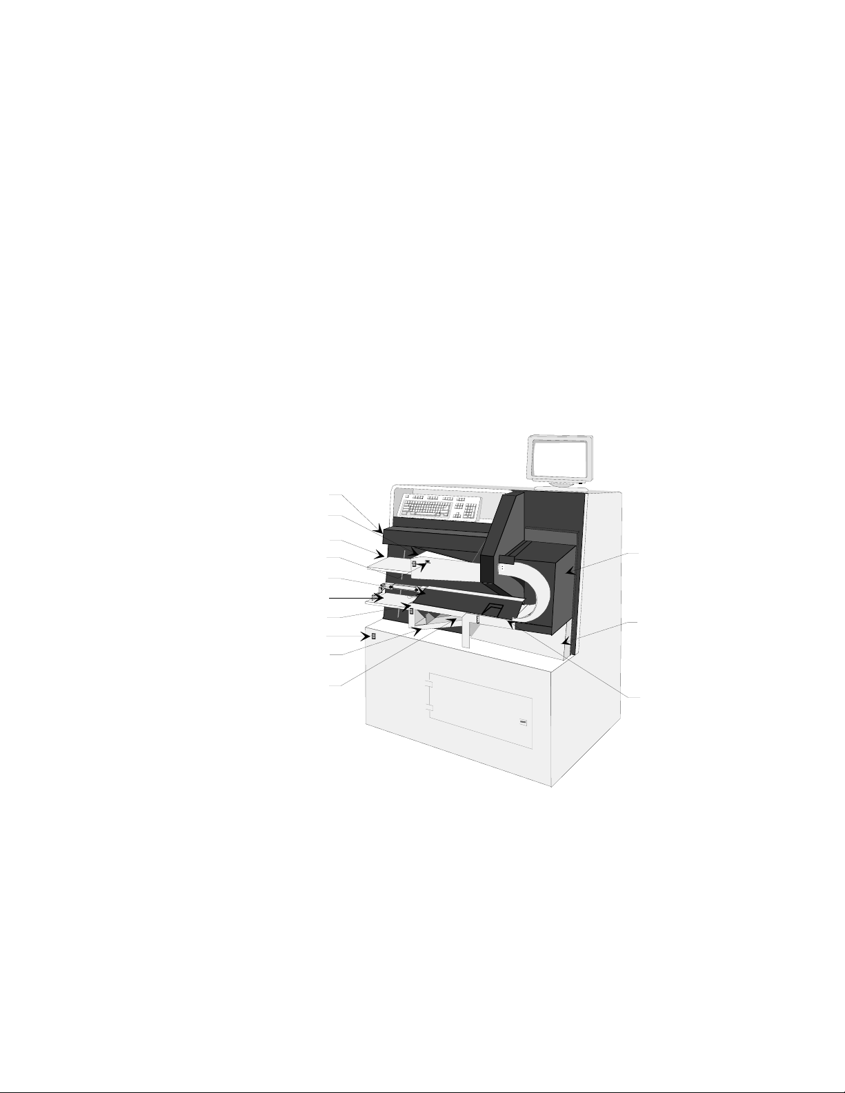
The OpScan iNSIGHT 70 is a device that captures the image of a form and sends
that image to a host computer for analysis. Figure 1-1 illustrates the parts of the
scanner.
UPPER DEFLECTOR
INPUT DECK
INPUT HOPPER
READY SWITCH
LOWER DEFLECTOR COVER
OUTPUT HOPPER
OUTPUT DECK
POWER SWITCH
SELECT STACKER
Chapter 1
Scanner Overview
TURNAROUND
PRINTER COVER
SHUNT GATE
Figure 1-1 Scanner Parts
PRINTER DECK
In a typical scanning session, these components function as follows:
• The power switch turns on the scanner and any other system components
that are plugged into the scanner's internal power strip.
• The READY switch starts and stops the scanner.
1-1
Page 12

Scanner Overview
Overview of the Scanner
• The input hopper holds the forms that are ready to be scanned. When the
scanner is made READY, the input hopper raises; when the scanner stops, the
hopper lowers, allowing you to load more documents. The input hopper
accepts stacks of up to 750 forms, depending on the thickness and condition of
the sheets.
• The input hopper height adjustment switch allows you to adjust the height
of the input hopper so that the scanner can pick a sheet. Refer to the Operator's
Guide for the OpScan iNSIGHT™ 70 Scanner for instructions on setting this
adjustment.
• The output hopper receives the forms that are successfully scanned. When the
scanner starts, the output hopper is raised; when the scanner stops, the stacker
is lowered, allowing you to remove the sheets. Before scanning, the output
sheet stop adjustment knob should be set to the length of the scanned forms
so they will stack properly. The output hopper height adjustment switch
adjusts the height at which the hopper halts. Refer to the Operator's Guide for
the OpScan iNSIGHT™ 70 Scanner for instructions on making these
adjustments.
• The scanner picks the forms from the input hopper one at a time. From there,
the form moves along the transport bed by rollers that continually drive the
form into the rail to remove possible skew. The form then passes through the
read heads where the cameras capture the image of the form.
• The form now goes through the turnaround station where the form is turned
over and sent to the wait station. At this point the software application
determines where the form should go. If the system includes the optional
transport printer, then any information that needs to be printed on the form
will be sent there. The form is imprinted as it passes over the print head. The
form is then sent to one of two places:
– The output hopper accepts up to 750 forms, depending on the thickness
and condition of the sheets. This hopper is reserved for forms that are read
with no errors.
– The select stacker accepts up to 200 forms, depending on the thickness
and condition of the sheets. The software controls the stacker's use. It is
used for forms with correctable and non-correctable system errors. For
example, if the system detects a multiple response on a grid, it sends the
form to the select stacker. The operator can fix the form and scan it again;
or, if the wrong form was scanned, it could be sent to the select stacker.
1-2 Installation Guide for the OpScan iNSIGHT 70 Scanner
Page 13
Typical Standalone Configuration
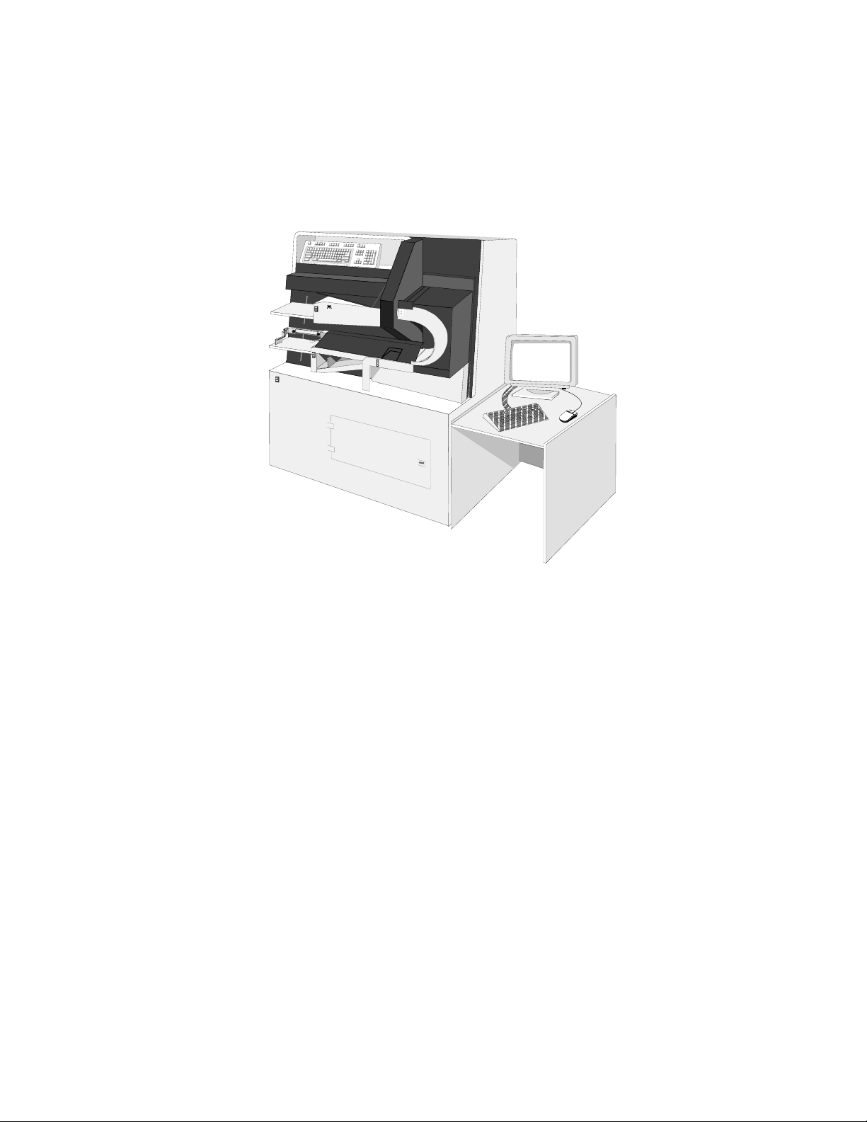
Figure 1-2 illustrates the components of a typical standalone OpScan iNSIGHT 70
scanner configuration. The form’s image is sent from the OpScan iNSIGHT 70
scanner to the computer for processing.
Scanner Overview
Typical Standalone Configuration
Figure 1-2 Scanner Standalone Configuration
1-3
Page 14

Scanner Overview
Customer Support
Customer Support
If you have a problem, call Pearson NCS Customer Support. An analyst will
respond to questions and concerns when they receive your call. Their only
requirement is that you first provide them with the information that they need to
help you.
IMPORTANT: Services no longer under warranty or covered under a service agreement,
may be billable. Your customer support representative will inform you if you require a
billable service.
This section tells you how to request and receive Customer Support assistance in
two steps:
• Calling requirements
• Calling procedure
Calling Requirements
To respond to questions and concerns about your scanner, Pearson NCS requires
that you provide certain information when you call for assistance. Pearson NCS
cannot process your request for service unless you satisfy these calling
requirements.
Read the list of requirements that follows. Check off each requirement as you
complete it. To place a request for service, you must provide Pearson NCS with
your:
1. Customer number
Your customer number is listed on the shipping documents that Pearson NCS
shipped with your scanner. If you do not have access to these documents, ask
the Customer Support operator for your customer number the first time you
call to request assistance.
Record your customer number for future use: ____________________
2. Scanner serial number and model number
The label on the scanner that contains the serial and model numbers is located
on the back of the scanner cabinet near the power cord and on the mechanism
plate under the outer turnaround deflector.
Note: Verify the serial and model numbers each time you call.
Record your scanner serial and model numbers for future use.
Serial Number ________________________
Model Number ________________________
1-4 Installation Guide for the OpScan iNSIGHT 70 Scanner
Page 15

Calling Procedure
The procedure used to request Customer Support assistance is simple and
straightforward. All that's required is that you provide some basic information
during your call. (Read the first part of this section for a list of the calling
requirements.)
To call Customer Support, follow these seven steps:
1. Be familiar with the procedures described in this manual.
2. Write down a description of the problem you are having to ensure that you
address all of your concerns with the Customer Support analyst.
3. Write down a description of the action(s) you have taken to resolve the
problem.
4. Note any error messages that are displayed on your computer's screen.
5. Be ready to provide the scanner serial number, your customer number, and
any other relevant information.
Scanner Overview
Customer Support
!
6. Call the Customer Support number—1-800-338-5544 — and describe the
problem that you are having with your scanner to the Pearson NCS dispatcher.
7. A dispatcher transfers your call to a Customer Support analyst.
If an analyst is not available, you can ask to be put on hold or request a return
call.
Customer Support typically returns the call within one hour and responds to
your questions about the problem that you reported.
WARNING: Pearson NCS cannot process a request for service without receiving certain basic
information from you. Your call cannot be accepted unless you can supply the scanner's serial
number and your customer number. Satisfy the calling requirements described in this section before
you call Pearson NCS!
Customer Support
Hours: Weekdays 8:00 a.m. to 5:00 p.m. Customer’s Local Time
(except for Alaska and Hawaii which is through 7:00 p.m. CST)
1-800-338-5544
Note: Customer support is not available on Pearson NCS holidays.
1-5
Page 16

Scanner Overview
Customer Support
1-6 Installation Guide for the OpScan iNSIGHT 70 Scanner
Page 17

Overview
This chapter describes how to set up and install the standalone OpScan iNSIGHT
70 scanner, the computer, the monitor, and the mouse.
The OpScan iNSIGHT 70 scanner system consists of the following components:
• Model OpScan iNSIGHT 70 scanner
• Computer
• SVGA monitor
• Duplex Heads (InfraRed/Red)
• Transport Printer (optional)
• Bar Code (optional)
Chapter 2
Scanner Installation
Preparation
Before assembling the standalone OpScan iNSIGHT 70 scanner, check to make
sure that you have all the hardware and accompanying documentation as listed
below.
Hardware
The following hardware components are required:
• Computer with SVGA monitor, keyboard, mouse, and furniture (standalone
only)
Documentation: Manufacturer's user manuals
• A model OpScan iNSIGHT 70 image scanner with interface card and cable
Documentation: Operator's Guide for the OpScan iNSIGHT™ 70 Scanner and the
Maintenance Manual for the OpScan iNSIGHT™ 70 Scanner
• Normalization and Calibration forms packet
Documentation: Operator's Guide for the OpScan iNSIGHT™ 70 Scanner
2-1
Page 18

Scanner Installation
Preparation
Software
The following software components are required:
• Microsoft
®
Documentation: The appropriate Windows operating system user’s guide
• Scanner application software
Documentation: ScanTools
• Scanner Exerciser diagnostic software (or equivalent)
Documentation: Operator's Guide for the OpScan iNSIGHT™ 70 Scanner and
Maintenance Manual for the OpScan iNSIGHT™ 70 Scanner
Installation Sequence
The installation sequence for the OpScan iNSIGHT 70 scanner is:
1. Check the installation site to verify that it is ready for setup and installation of
the scanner with its computer, monitor, keyboard, and mouse.
2. Install the scanner.
3. Install the computer, monitor, keyboard, mouse, and furniture.
Windows XP® operating system software
®
Plus User's Guide
4. Check the voltages.
5. Connect the network cables (optional).
6. Configure the internet network addresses and test the network (optional).
7. Verify that all software has been pre-loaded.
8. Run the Scanner Exerciser Utility to check the following:
• Sheet feeding (See Scan Sheets menu).
• Selecting and printing (See Scan Options menu).
• Color selection (See Configuration).
9. Run Scanner Exerciser to check alignment (See Check Alignment).
10. Run the appropriate Camera Setup utility
alignment and focus.
11. Run the Normalize and Calibrate Utility on the scanner.
12. Run sample application using ScanTool Plus.
13. Power off the system.
The above installation sequence and the following instructions serve as a typical
step-by-step guide only. They may not exactly fit your setup.
1
to check and adjust camera/mirror
1. For detailed information on how to run Camera Setup or Fast Camera Setup, refer to the Maintenance
Manual for the OpScan iNSIGHT 70 Scanner, Chapter 3.
2-2 Installation Guide for the OpScan iNSIGHT 70 Scanner
Page 19

Checking the Installation Site
Before you begin installing the OpScan iNSIGHT 70 scanner, verify the following
site conditions:
• Check the physical dimensions of the selected site to ensure adequate space.
– The OpScan iNSIGHT 70 scanner is 57.5 inches high, 48 inches wide, and
29 inches deep.
– If the scanner is near a wall, be sure to leave approximately 24 inches of
space between the scanner and the wall. This space is required so that an
operator can open the rear panel doors.
• Check that the site selected for the scanner meets all power and
environmental requirements.
– The temperature must be between 60
– The humidity must be between 40% and 60% (non-condensing).
• Heat dissipation is 5300 - 5500 BTU/hr.
• Check that the circuit from the power source is a dedicated circuit for the
scanner.
Scanner Installation
Checking the Installation Site
o
and 80o Fahrenheit (16 - 27 C).
2-3
Page 20

Scanner Installation
Installing the Scanner
Installing the Scanner
The OpScan iNSIGHT 70 scanner is delivered to the customer shrink-wrapped
and up-right on its own four casters. Roll the scanner to its permanent location.
Unpacking the Scanner
To unpack the scanner, do the following:
1. Remove the clear vinyl dust cover.
Caution: Do NOT throw the clear vinyl dust cover away. It can be used to protect the
scanner during periods of non-use or when moving it to another location.
2. Remove the clear plastic shrink-wrap.
3. Remove the packing materials (sheets of paper) located:
• on the transport bed,
• on the hopper tables, and
• between the read head glass.
Spares
4. Remove the packing materials (blocks of styro-foam) located:
• between the printer deck and printer cover (holds the printer cover in
place), and
• between the sliding tray for the PC and interior bulkhead (prevents the PC
tray from sliding during shipping).
A separate box of spares is provided with each scanner. This includes the
following:
• Retard pads
• Pick belts
• Manuals
• A key for the front panel door
Note: For safekeeping, place the key in the hole located below the printer deck and to the
left of the printer cover. Keep the spare retard pads and pick belts in a safe place such as on
the computer shelf inside the scanner cabinet. These spares are used as replacements (See
the Operator's Guide for the OpScan iNSIGHT™ 70 Scanner for instructions on
removing/replacing retard pads and pick belts).
2-4 Installation Guide for the OpScan iNSIGHT 70 Scanner
Page 21

Checking the Voltage
Before you plug the OpScan iNSIGHT 70 scanner into the designated wall outlet,
the following power and grounding requirements must be met and maintained to
ensure optimum performance of the scanner and its peripherals. To verify that the
power and grounding requirements have been met, refer to the following topics:
Power Noise, Grounding, and Site Power Wiring Recommendations.
Power Noise
The OpScan iNSIGHT 70 scanner is designed to operate satisfactorily under
conditions of reasonable input power noise. Input power noise specifications are
as follows:
Table 2-1 Input Power Noise Specifications
Condition Description
Definitions Surge or Sag - any sudden positive or negative excursion in the level of
Scanner Installation
Installing the Scanner
the input voltage having a duration from 0.005 to 5 seconds.
Transient - any sudden positive or negative change in the level of the
input voltage having a duration of between 1 nanosecond and 5
milliseconds.
Limits No surge or sag shall exceed ± 15% of the normal rated voltage. However,
the surge or sag shall be considered acceptable provided its amplitude
does not exceed ± 50% of the normal rated voltage and it returns to the
steady-state rated level within 3 cycles of input power.
Recommendations Dedicate a feeder line between the main building power panel and the
system branch circuit power panel serving the OpScan iNSIGHT 70
system.
If transients, surges, or sags outside of the limits stated above exist with a
dedicated feeder, do one or both of the following.
• Install a line conditioner to limit transients.
• Use a constant-voltage isolation transformer to control surges or sags.
Grounding
Proper system grounding is extremely important to the safe and reliable
operation of the system. The OpScan iNSIGHT 70 scanner ground must meet two
requirements:
1. It must serve as a return path for current in case of a short circuit between the
power line and the chassis of any system component.
2. It must serve as the ground reference point for the OpScan iNSIGHT 70 system
components and data cables.
2-5
Page 22

Scanner Installation
Installing the Scanner
Dedicated Ground
A dedicated isolated/insulated ground for the OpScan iNSIGHT 70 system must
be provided. If possible, route a dedicated ground conductor between the main
power panel and the OpScan iNSIGHT 70 system branch circuit (with the
dedicated feeder). If a dedicated ground conductor is not feasible, then another
code-approved method must be used. (The isolated ground conductor is noted in
the National Electrical Code, Section 250-74, Exception 4.) Use of an isolated
ground rod or grounding to a water pipe is not acceptable.
An isolated/insulated ground conductor, equal to or larger in size than the
heaviest gauge AC feeder conductor in the circuit, should be bonded to the
ground bus in the building main power panel. Route it with the circuit conductors
in the wiring conduit. Pass this ground through any intermediate panel boards
without connection to the panel board grounding terminal bars. The National
Electric Code, cited above, allows for the installation at the intermediate panel
board of an isolated ground bus, constructed from a terminal block kit, for the
interconnection of the isolated ground conductor.
This isolated/insulated ground conductor runs as a single, uninterrupted circuit
between the building main power panel and the OpScan iNSIGHT 70 system
branch power panel. It forms the interconnection point for the third-wire grounds
of all OpScan iNSIGHT 70 system components. Connect all OpScan iNSIGHT 70
system component third-wire grounds to this ground; do not connect any
equipment other than OpScan iNSIGHT 70 system components to this ground
conductor. This condition is met if all system components are plugged into the
switched convenience outlet in the base of the scanner.
Note: At some sites, local regulations require that all installed equipment be connected to
a system common ground. In this case, connect all OpScan iNSIGHT 70 system
components to the common ground at only one point. Connect third-wire grounds of
system components into a common bus connected to the common ground at a single point.
Note: Make sure the equipment third-wire ground (green wire) does not become
connected to the conduit at the outlet box or connector. To avoid an inadvertent connection,
use a NEMA 5-20R type isolated-ground receptacle such as a Hubble IG-5362.
Grounding in Multi-Story Buildings
When installing the OpScan iNSIGHT 70 system in a multi-story building,
provide a low noise ground by connecting the isolated ground of the system to
the structural steel of the building. Install the isolated ground system as described
above. In addition, bond one end of a heavy gauge wire or copper braid to the
isolated ground bus in the branch circuit panel serving the OpScan iNSIGHT 70
system. Weld the other end of this wire or braid to the nearest vertical steel
structural member. Do not substitute a water pipe or an isolated ground rod for
the vertical steel member.
Ground-To-Neutral Specifications
With circuit power turned off, the resistance between the circuit neutral
conductor and the isolated ground conductor must be less than 2.1 ohms.
2-6 Installation Guide for the OpScan iNSIGHT 70 Scanner
Page 23

Scanner Installation
Installing the Scanner
With circuit power on and all OpScan iNSIGHT 70 system components
unplugged, the voltage between the circuit neutral conductor and the isolated
ground conductor must be less than 0.6 VAC.
Site Power Wiring Recommendations
Table 2-2 describes the conditions for power wiring at a scanner site.
Table 2-2 Power Wiring at a Scanner Site
Condition Description
Dedicated
Feeder
Dedicated
Isolated/
Insulated
Ground
Panel Branch
Circuits
Additional Utility
Convenience
Connectors
Scanner
Electrical
Connections
Run a separate dedicated feeder from the building main power panel to the
branch power panel serving the OpScan iNSIGHT 70 system. The cabling
should be of sufficient diameter to produce no less than 110V at the outlet
when the scanner is connected and powered on. This feeder should be a
minimum of 30 amp service to allow for future growth of the system.
An isolated/dedicated ground is required. Run this ground conductor as an
uninterrupted circuit from the power panel to the OpScan iNSIGHT 70
system branch panel. The gauge of this conductor must be at least as large as
that of the AC circuit conductors in all stages of the circuit.
All branch circuits leaving the OpScan iNSIGHT 70 branch power panel
should be at least 10 AWG copper wire. There should be no circuits from
this power panel serving devices that are not part of the scanner system.
One branch circuit from this power panel should be dedicated at the scanner
(this circuit will also service the computer and monitor), and there should be
at least one additional dedicated circuit for each additional scanner.
Provide additional convenience outlets in the vicinity of the OpScan
iNSIGHT 70 scanner. Connect these outlets (may be used for vacuums,
paper joggers, and other electrical devices) to a branch panel other than the
scanner branch panel to provide maximum noise isolation for the OpScan
iNSIGHT 70 system components.
Dedicate one 15 amp (120 VAC) or 7.5 amp (220 VAC) circuit to each
OpScan iNSIGHT 70 scanner at the site. All may be served from the same
branch panel, provided its rated capacity is not exceeded.
Electrical
Outlets
All 120V outlets for the OpScan iNSIGHT 70 scanner should be Hubble
IG-5362 or equivalent (NEMA 5-20R). All 240V outlets should be Hubble
IG2410A or equivalent. Outlets for the peripheral equipment should be of
the type and rating specified in the hardware reference manuals for the
equipment.
The quantity of outlets that must be provided for the peripheral equipment
varies according to system configuration. (See Panel Branch Circuits above.)
Outlets should be located within 6 feet (2 meters) of the working location of
the equipment.
2-7
Page 24

Scanner Installation
Installing the Scanner
Electrical Requirements
The steady-state line-to-neutral voltage should be maintained within -10% to +5%
of the normal rated voltage. The short term and long term frequency variations
must be maintained at less than ±5% of the specified power line frequency as
measured at the input power side of the scanner when it is powered on. Table 2-3
lists the electrical requirements for the power operation of the OpScan iNSIGHT
70 scanner.
Table 2-3 Electrical Requirements
Frequency
Power
Standard 60 HZ ±5% 115V ±10% On 15 Amp., single-phase dedicated circuit
Option 1 50 HZ ±5% 100 or 110V ±10% On 15 Amp., single-phase dedicated circuit
Option 2 50 HZ ±5% 220 or 240 V ±10% On 7.5 Amp., single-phase dedicated circuit
After you have verified the power and grounding requirements, perform the
"Power Supply Check-out Procedures."
Limits Voltage Limits Other data
Power Supply Check-out Procedures
Perform the following checks with the scanner on but with the transport bed
motor off (unless otherwise directed by the procedure).
The OpScan iNSIGHT 70 scanner is equipped with four power supplies. They are:
• 914 022 769, +12V 250W Power Supply
• 914 022 264, +12V 200W Solenoid Boost Power Supply (Unregulated)
• 914 022 744, +5V Power Supply (LEDs)
• 914 022 751, +5V and ±15V Logic Power Supply
The +12V, 250W power supply produces +12.5V for the transport bed solenoids
and hopper drive motors. The +12V, 200W, power supply produces +12V boost
voltage to pull the solenoids. The +5V power supply produces +5V for the read
head LEDs. The logic power supply produces +5V, +15V and -15V logic power for
the cameras and various scanner PC boards.
The logic power supply and the LED power supply require periodic check-out
and adjustment. In addition, the 12V, 250W power supply needs to be adjusted to
12.5V. If any voltage is outside the proper range, adjust the outputs as described
in the following "Logic Voltage Checkout Procedures." If you cannot adjust the
output, replace the power supply. There are no field repair procedures for any of
the scanner's power supplies.
2-8 Installation Guide for the OpScan iNSIGHT 70 Scanner
Page 25

Scanner Installation
Installing the Scanner
Logic Voltage Check-out Procedure
The outputs of the power supplies are read at their most critical point-the input to
the Camera Controller Board, the Solenoid Clutch Activation Board, and the Top
LED Mother Board.
1. Turn on the scanner power switch.
2. Use a DVM to measure the outputs to the voltages listed in Table 2-4. Be sure
to connect your ground probe to TPG1, TPG2, TPG3, or TPG4 on the Camera
Controller Board.
Table 2-4 Logic Voltages
Solenoid Clutch
Camera
Nominal
Volta g e
+5V J5 - 3 +4/95 to + 5.20V DC
-15V J5 - 1 -15 to - 15.20V DC
Controller Pin
Location
Activation
Board (SCAB
Pin Location
Top LED
Mother Board
Pin Location Acceptable Range
+15V J5 - 2 +15.0 to -15.20V DC
Ground TPG1, TPG2,
TPG3, TPG4
+12.5V J9 - 4 +12.5 to +13V
+V Boost J9 - 7 +12 to +16V
+5V J3 - 1 +5 to +5.5V
+12V Boost Power Supply
There are no adjustments to the +12V, 200W boost power supply. If its output is
not +12.5V to 16V, replace the supply.
Location of the Power Supplies
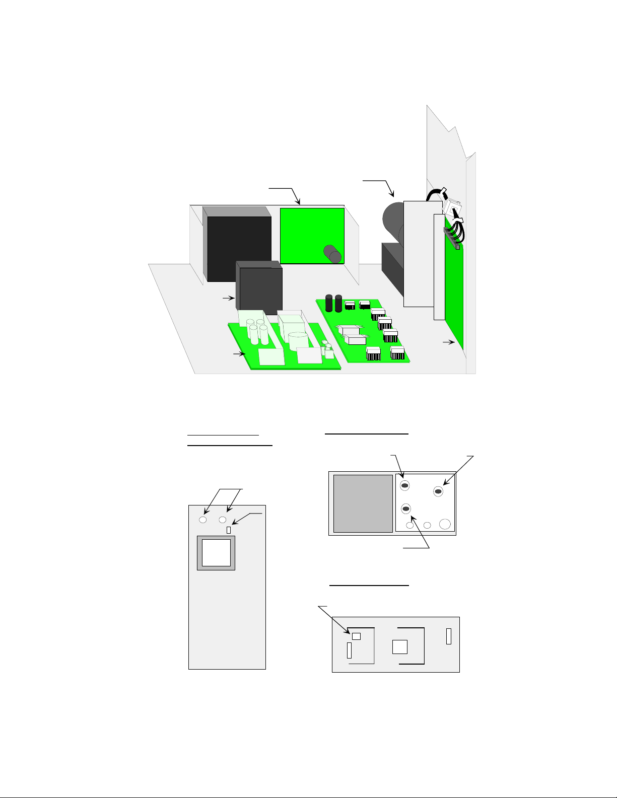
Figure 2-1 and Figure 2-2 illustrate the location of the power supplies and the
location of the adjustment potentiometers. The power supplies that may require
checkout and periodic adjustments are:
• +12V, 250W, Solenoid and DC Motors Power Supply (adjusted to +12.5V)
• +5V LED Power Supply
• +5V and ±15V Logic Power Supply
Note: The Logic Power Supply is labeled ±12V, but it should be adjusted to ±15V.
2-9
Page 26
Scanner Installation
Installing the Scanner
+5, +/-15V Logic Supply
Printer
Transformer
+5V LED
Supply
Solenoid Boost Voltage
Solenoid
and DC
Motors
Supply
PWRC Board
Figure 2-1 Location of the Power Supplies
Solenoid and DC
Motor Power Supply
DC Output
+12.5V
Adjustment
Logic Power Supply
+15V Adjustment
-15V Adjustment
LED Power Supply
+5V Adjustment
+5V Adjustment
Figure 2-2 Adjustment Locations
2-10 Installation Guide for the OpScan iNSIGHT 70 Scanner
Page 27
Installation of Host Computer and
Overview
This chapter provides information on setting up and installing the computer and
other peripheral components in a OpScan iNSIGHT 70 scanner standalone or
network configuration. Installation information on optional equipment, such as a
system printer and/or Bar Code Reader, is also provided.
Begin by unpacking the computer, the monitor, and the keyboard. Unpack other
equipment as required. Refer to the manufacturer's user manuals for installation
instructions and assistance when performing the procedures discussed on the
following pages.
Caution: The monitor and printer power cords should be plugged into AC wall outlets or a
power strip located outside the scanner.
Chapter 3
Peripherals
There may be situations where you are installing additional OpScan iNSIGHT 70
scanners, additional peripheral equipment, or printers and you need to power the
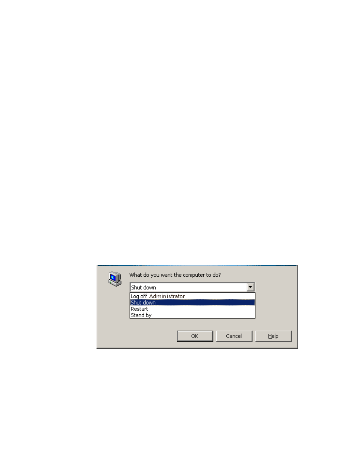
system down. In this case, you should use the following shutdown procedures.
• Hold down the ALT key and press F4. The following menu is displayed.
• Highlight the Shut down option.
• Click OK.
3-1
Page 28
Installation of Host Computer and Peripherals
Standalone Installation
Standalone Installation
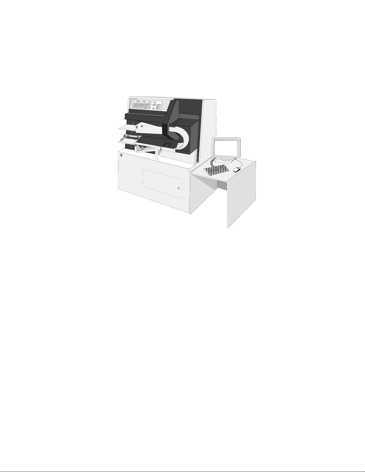
The OpScan iNSIGHT 70 scanner in a standalone configuration requires a
computer, a monitor, a keyboard, a mouse, and a table (for the monitor, keyboard,
and mouse). An optional printer may also be installed.
Host Computer
This section discusses installation and internal cabling for the host computer in a
standalone configuration.
Installation
Do the following.
1. Remove the computer’s cover.
Caution: Use ESD precautions (including a grounded wrist strap) for step 2.
2. Make sure that the scanner interface cards and all ribbon cables are fully
seated.
3. Replace the cover on the computer.
4. Open the rear panel doors and place the computer on the shelf. The front of the
computer must face the front of the scanner.
Figure 3-1 Standalone Configuration
3-2 Installation Guide for the OpScan iNSIGHT 70 Scanner
Page 29

Installation of Host Computer and Peripherals
Standalone Installation
Cabling
In preparation for cabling, Pearson NCS recommends that you do the following:
• Set the computer on the back lip of the shelf during cable installation so that
the back of the computer is tilted up. This provides easier access to the
computer's ports.
• Uncoil all cords and cables, separate them, and lay them out on the floor.
The following cabling instructions are for a standalone configuration. Refer to
Figure 3-4, Figure 3-5, and Table 3-1 at the end of this chapter.
1. Install the computer power cord.
• Attach the power cord connector to the back of the computer.
• Ensure that the other end is plugged into the scanner's power strip.
2. Complete installation of the 25-pin straight through cable from the PRTCON
board (for the optional printer) to the back of the computer.
• One end of this cable is already attached to the PRTCON board.
• Connect the other end to the back of the computer.
3. Complete installation of one 6-pin DIN cable from the KEMCON board (for the
keyboard) to the back of the computer.
• One end of this cable is already attached to the KEMCON board.
• Connect the other end to the back of the computer in the keyboard port.
4. Complete installation of the other 6-pin DIN cable from the KEMCON board
(for the mouse) to the back of the computer.
• One end of this cable is already attached to the KEMCON board.
• Connect the other end to the back of the computer in the mouse port.
5. Complete installation of the 5 BNC/15-pin DIN cable from the bulkhead (for
the monitor) to the back of the computer.
• One end (5 BNC end) is already attached to the bulkhead.
• Connect the other end (15-pin DIN) to the back of the computer.
Note: Connect this cable to the 15-pin connector on the video card in the first
expansion slot. Do not connect to the 15-pin connector on the system board.
6.
Complete installation of the 50-pin high density ribbon cable from the Camera
Controller board to the Hobbes interface connector on the computer.
• One end of this cable is already connected to the scanner's Camera
Controller board at J1.
• Connect the other end to the external connector for the scanner interface
(Hobbes) card (P2) on the back of the computer.
3-3
Page 30

Installation of Host Computer and Peripherals
Standalone Installation
7. Complete installation of one 9-pin D cable from the Scanner Controller main
board to the Com1 port on the back of the computer.
• One end of this cable is already attached to the scanner's Scanner
Controller main board at J9.
• Connect the other end to the Com1 port on the back of the computer.
Once all computer cabling connections have been made, set the computer on the
shelf, coil any extra cabling under the computer shelf, and close the rear panels.
Work Table
The standalone OpScan iNSIGHT 70 scanner comes with a work table. This work
table is for the monitor, the keyboard, and the mouse. Instructions for assembling
the work table are provided by the manufacturer.
Monitor and Keyboard
Place the monitor, the keyboard, and the mouse on the work table. The monitor,
the keyboard, and the mouse need to be cabled to the computer. (See Figure 3-5
for cable locations.)
Monitor
1. Connect the power cord:
• Plug the female end of the power cord into the port labeled AC Outlet on
the back of the monitor.
• Plug the other end (male end) into an AC wall outlet or power strip.
2. Ensure that the monitor cable is connected. (See Step 6 under cabling.)
3. Complete 5 BNC cable install from the bulkhead to the back of the monitor.
• Connect one end of this cable to the bulkhead. Install the cable according
to the colors labeled on the bulkhead.
• Connect the other end (15-pin) to the back of the monitor.
Keyboard and Mouse
1. Plug the keyboard cable connector into the port labeled KEYBOARD located on
the scanner's back panel (bottom and second cutout from the left).
2. Plug the mouse cable connector into the port labeled MOUSE located on the
scanner's back panel (bottom and second cutout from the left).
3-4 Installation Guide for the OpScan iNSIGHT 70 Scanner
Page 31
Installation of Host Computer and Peripherals
Standalone Installation
Board/Connector Relationship
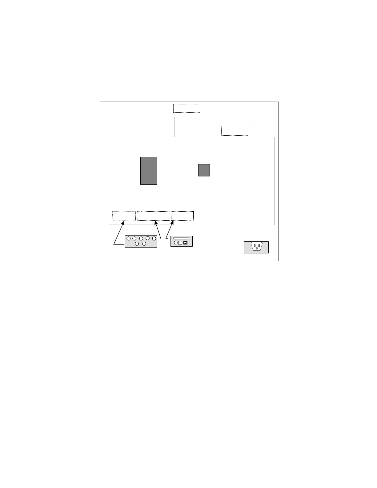
Figure 3-2 illustrates the relationship between PC boards attached to the bulkhead
inside the cabinet and the connectors on the exterior surface of the cabinet.
Note: There is a LINE PRINTER/NETWORK connector on the bottom left side of the
cabinet. Only the LINE PRINTER connector is used in a standalone configuration.
SCANNER
CAMERA
CONTROLLER
BOARD
CONTROLLER
MAIN BOARD
KEMCON
No Board Required for
Monitor (Pass Through)
MONITOR
KEYBOARD MOUSE
PRTCON
LINE PRINTER
NETWORK
Figure 3-2 Standalone Board/Connector Locations
INPUT POWER
3-5
Page 32
Installation of Host Computer and Peripherals
Network Installation
Network Installation
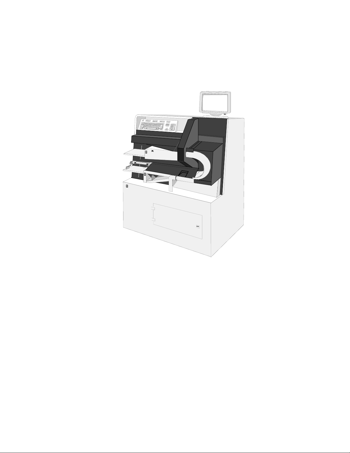
The OpScan iNSIGHT 70 scanner in a network configuration requires an Pearson
NCS-supplied computer, monitor, keyboard, mouse and required networking
equipment. An optional printer may also be installed.
Figure 3-3 Network Connection
Computer
This section discusses installation and internal cabling for the host computer in a
network configuration.
Installation
Do the following.
1. Remove the computer’s cover.
Caution: Use ESD precautions (including a grounded wrist strap) for step 2.
2. Make sure the scanner interface cards and all ribbon cables are fully seated.
3. Replace the cover on the computer.
4. Open the rear panel doors and place the computer on the shelf. The front of the
computer must face the front of the scanner.
3-6 Installation Guide for the OpScan iNSIGHT 70 Scanner
Page 33

Installation of Host Computer and Peripherals
Network Installation
Cabling
In preparation for cabling, Pearson NCS recommends that you do the following:
• Set the computer on the back lip of the shelf during cable installation so
that the back of the computer is tilted up. This provides easier access to the
computer's ports.
• Uncoil all cords and cables, separate them, and lay them out on the floor.
The following cabling instructions are for a network configuration. Refer to
Figure 3-3, Figure 3-4, Figure 3-5, and Table 3-1.
1. Install the computer power cord.
• Attach the power cord connector to the back of the computer.
• Ensure that the other end is plugged into the scanner's power strip.
2. Complete installation of the 25-pin straight through cable from the PRTCON
board (for the optional printer) to the back of the computer.
• One end of this cable is already attached to the PRTCON board.
• Connect the other end to the back of the computer.
3. Complete installation of the network cable (10BaseT, 10Base2, or Token Ring)
from the NETCON board (for the network) to the back of the computer.
• One end of this cable is already attached to the NETCON board.
• Connect the other end to the back of the computer.
4. Complete installation of one 6-pin DIN cable from the KEMCON board (for the
keyboard) to the back of the computer.
• One end of this cable is already attached to the KEMCON board.
• Connect the other end to the back of the computer in the keyboard port.
5. Complete installation of the other 6-pin DIN cable from the KEMCON board
(for the mouse) to the back of the computer.
• One end of this cable is already attached to the KEMCON board.
• Connect the other end to the back of the computer in the mouse port.
6. Complete installation of the 5 BNC/15-pin DIN cable from the bulkhead (for
the monitor) to the back of the computer.
• One end (5 BNC end) is already attached to the bulkhead.
• Connect the other end (15-pin DIN) to the back of the computer.
Caution: Connect this cable to the 15-pin connector on the video card in the first
expansion slot. Do not connect the cable to the 15-pint connector on the system board.
7. Complete installation of the 50-pin high density ribbon cable from the Camera
Controller board to the Hobbes interface connector on the computer.
• One end of this cable is already connected to the scanner's Camera
Controller board at J1.
• Connect the other end to the external connector for the scanner interface
(Hobbes) card (P2) on the computer.
3-7
Page 34

Installation of Host Computer and Peripherals
Network Installation
8. Complete installation of one 9-pin D cable from the Scanner Controller main
board to the Com1 port on the back of the computer.
• One end of this cable is already attached to the scanner's Scanner
Controller main board at J9.
• Connect the other end to the Com1 port on the back of the computer.
Once all computer cabling has been made, set the computer on the shelf, coil any
extra cabling under the computer shelf, and close the rear panels.
Monitor and Keyboard
Place the monitor on top of the scanner on the right-hand side (See Figure 3-3).
Install the keyboard using the four pressure sensitive adhesive backed velcro
pads that were shipped with the keyboard. Peel off the paper backing on one side
of the pads and affix to the four corners of the keyboard. Peel off the paper
backing from the other side and affix the keyboard to the angled shelf on the
upper left-hand side of the scanner. Place the mouse and mouse pad on the flat
surface just to the right of the keyboard (See Figure 3-3).
To cable the monitor and the keyboard to the computer, do the following:
Cabling the Monitor
1. Attach the power cord.
• Plug the female end of the power cord into the back of the monitor.
• Plug the male end into a nearby AC power outlet or a power strip.
2. Ensure the monitor cable is properly connected. (Refer to Step 7, "Cabling.")
3. Complete 5 BNC cable install from the bulkhead to the back of the monitor.
• Connect one end of this cable to the bulkhead. Install the cable according
to the colors labeled on the bulkhead.
• Connect the other end (15-pin) to the back of the monitor.
Cabling the Keyboard and Mouse
1. Plug the keyboard cable into the port labeled KEYBOARD located behind the
angled panel next to the keyboard.
2. Plug the mouse cable into the port labeled MOUSE located behind the angled
panel next to the keyboard.
3-8 Installation Guide for the OpScan iNSIGHT 70 Scanner
Page 35

Networking Equipment
OpScan iNSIGHT 70 scanners may be integrated into networking configurations
consisting of third-party equipment.
The appropriate vendor personnel are responsible for unpacking, setting up,
configuring, and testing the networking equipment. Pearson NCS field engineers
are responsible for positioning the networking equipment in accordance to the
system and network layout plans. These plans should be made available by the
site preparation project manager.
Once the OpScan iNSIGHT 70 scanner has been installed and the networking
equipment has been positioned, you can now connect the scanner to the network
cable. Before connecting the cable to the system, verify the following:
• The scanner is positioned in the appropriate location.
• The network cable is installed.
• The OpScan iNSIGHT 70 scanner and peripherals are turned off.
• The cable is in good condition. It should not be crimped, have damaged
insulation, and it should not be placed near heat sources, power cables, or
high traffic areas without adequate protection.
Installation of Host Computer and Peripherals
Network Installation
Connecting a Scanner to a Network
1. Locate the network cable for the scanner. A network connector (10BaseT,
10Base2, or Token Ring) should be attached to the network cable and located
near each scanner (if more than one).
2. Attach the network connector (10BaseT, 10Base2, or Token Ring) to the jack
labeled NETWORK located on the scanner's back panel (bottom and second
cutout from the left).
3. Repeat steps 1 and 2 for each additional scanner.
4. Connect the other end of each network cable (from each scanner) to the
network concentrator.
5. Locate and attach the cable from the concentrator to the connector jack located
on the back of the file server.
3-9
Page 36
Installation of Host Computer and Peripherals
Network Installation
Board/Connector Relationship
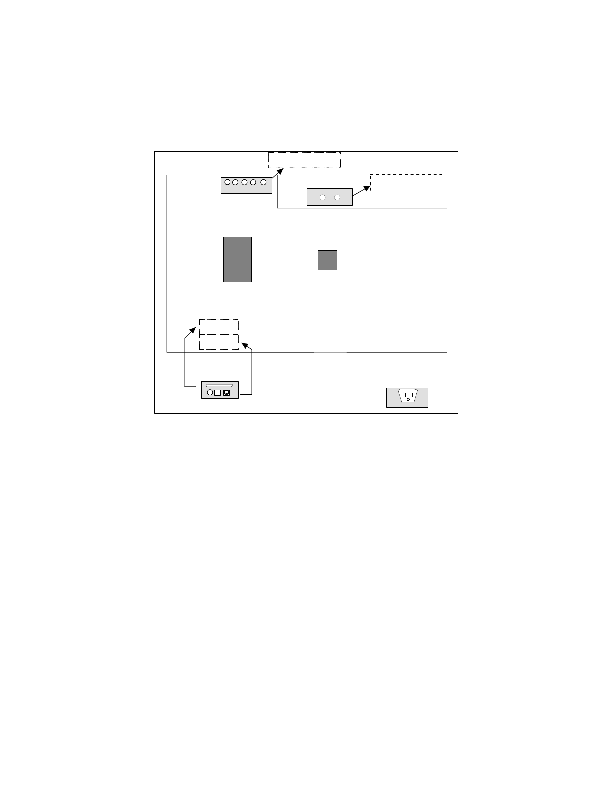
Figure 3-4 illustrates the relationship between PC boards attached to the bulkhead
inside the cabinet and the connectors on the exterior surface of the cabinet in a
network configuration.
No Board Required for
Monitor (Pass Through)
MONITOR
CAMERA
CONTROLLER
BOARD
PRTCON
NETCOM
KEYBOARD MOUSE
SCANNER
CONTROLLER
MAIN BOARD
KEMCON
LINE PRINTER
NETWORK
Figure 3-4 Network, Board/Connector Locations
INPUT POWER
3-10 Installation Guide for the OpScan iNSIGHT 70 Scanner
Page 37
Internal Cable Connections
This section provides additional information regarding connection of the monitor,
keyboard, mouse, cameras, power, network, and printer (optional) cables to the
appropriate connectors on the boards located inside the scanner (Figure 3-4).
Note: The PRTCON, NETCON, and KEMCON, boards are attached to the interior of the
scanner's bulkhead to provide an appropriate exterior connection to both standard and
optional devices.
The PC boards include the following:
• Scanner Controller main board (bed control logic).
• Camera Controller board (camera, light source, and pixel normalization logic).
• NETCON board (Network).
• KEMCON board (Keyboard and mouse).
• PRTCON board (Printer, optional).
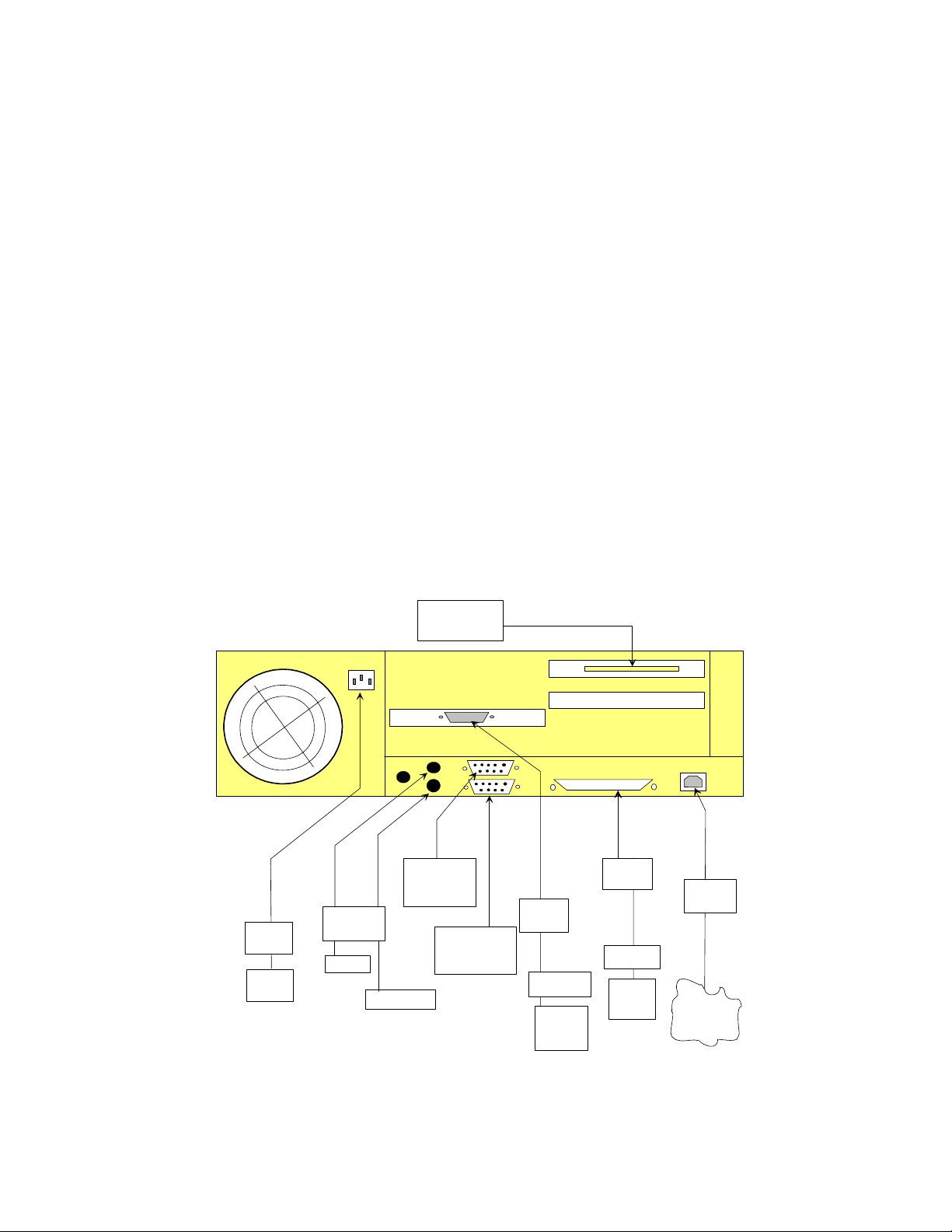
The schematic in Figure 3-5 identifies the cable connections to the appropriate
boards and the appropriate connections of these cables to ports on the computer.
The scanner is shipped with the cables already connected to the appropriate
boards. Because the computer is shipped separately, you must install the
computer and then make the necessary cable connections.
Note: The configuration may change depending on computer model.
CAMERA
HOST COMPUTER
CONTROLLER
BOARD
Installation of Host Computer and Peripherals
Internal Cable Connections
J1
Flat Cable
OUTLET
STRIP
INPUT
POWER
Power
Hobbes
Com2
)
s
g
u
l
N
P
I
D
d
n
n
i
u
o
P
R
6
(
KEMCON
BOARD
MOUSE
Com1
D
n
)
s
g
u
l
N
P
I
D
d
n
n
i
u
o
P
R
6
(
i
P
9
BAR CODE
READER
BCD BOARD
D
n
i
P
9
J9
SCANNER
CONTROLLER
MAIN BOARD
BULKHEAD
D
n
i
P
5
1
/
s
C
N
B
5
s
C
N
B
5
D
n
i
P
5
2
PRTCON
BOARD
PRINTER
MONITOR
KEYBOARD
AC
WALL
OUTLET
WALL
OUTLET
Figure 3-5 Computer and PC Board Connections
AC
D
n
i
P
5
2
or 10BASE2
NETWORK
NETCON
BOARD
10 BASET
l
a
i
x
a
o
C
/
r
a
l
e
u
l
d
b
o
a
C
M
e
l
b
a
C
/
r
l
a
a
l
i
u
x
d
a
o
o
C
M
3-11
Page 38

Installation of Host Computer and Peripherals
Optional Equipment
Table 3-1 lists cables, part number, and host computer connectors.
Table 3-1
Part Number Description Type PC Connection
322 701 004 Scanner controller 9-pin D Com1
342 915 006 Hobbes, camera controller 50-pin flat cable Hobbes connector
920 256 005 Bulkhead to Monitor 5 BNCs N/A
913 406 005 Gender Changer HD 15 Female/Female N/A
920 256 013 Bulkhead to PC 5 NBCs/15-pin D Video
920 401 015 Keyboard/Mouse connectors (2) 6-pin DIN (round plug) Keyboard/Mouse
920 401 023 Printer connector 25-pin D Parallel
913 027 017 Phone - 14’ wire male Modular cable 10BaseT
920 255 007 BNC Coaxial, 8’ Coaxial 10Base2
315 941 013 Bar code to PC (optional) 9-pin D Com2
Optional Equipment
Optional equipment includes system printers and the Bar Code Reader.
System Printers
Cabling for system printers is slightly different for standalone and network
configurations.
Standalone Printer
Unpack the printer and place it on the printer cabinet (a separate piece of
furniture). Follow the instructions in the manufacturer's user manuals and install
the printer as a parallel device. Use the 25-pin parallel interface cable to connect
the printer to the port labeled LINE PRINTER located on the scanner's back panel
(bottom and first cutout from the left).
For cabling instructions, do the following:
1. Attach the power cord.
• Plug the female end into the back of the printer.
• Plug the male end into the power strip (or wall outlet).
2. Attach the parallel interface cable.
• Plug the male end of the parallel interface cable into the appropriate port
on the back of the printer.
• Plug the other end of the cable into the appropriate port labeled LINE
PRINTER located on the lower left-hand side of the scanner's back panel.
3-12 Installation Guide for the OpScan iNSIGHT 70 Scanner
Page 39

Installation of Host Computer and Peripherals
Optional Equipment
Network Printer
Unpack the printer and place it on the printer cabinet (a separate piece of
furniture). Follow the instructions in the manufacturer's user manuals and install
the printer as a parallel device, using the parallel interface cable to connect the
printer to the network server or to a port located on the back of the scanner.
For cabling instructions, do the following (See Figure 3-5):
1. Attach the power cord.
• Plug the female end into the back of the printer.
• Plug the male end into the power strip.
2. Attach the parallel interface cable.
• Plug the male end of the parallel interface cable into the port on the back
of the printer.
• Plug the other end of the cable into the appropriate port on the back of the
network server or to a port labeled LINE PRINTER located at the bottom
of the scanner's rear panel.
Bar Code Reader
The optional Bar Code Reader is usually installed at Pearson NCS Manufacturing.
It can also be installed in the field by a Pearson NCS technician. In both cases, the
following cable connections must be performed as part of the initial installation.
There are two cables:
• 25-pin flat cable (I/O cable)
• 25-pin D-SUB to 9-pin D-SUB cable (Bar Code to PC cable)
The 25-pin flat cable has been pre-installed at Pearson NCS Manufacturing. You
need to locate the 9-pin D-SUB end of the Bar Code to PC cable and plug it into
the Com2 serial port on the back of the computer.
1. Ensure that the female end of the 25-pin flat cable is securely connected to the
BCD board.
2. Ensure that the other end (also female) is securely connected to the 25-pin
D-SUB end of the Bar Code to PC cable.
3. Plug the 9-pin D-SUB end of the Bar Code to PC cable into the Com2 port on
the back of the computer.
3-13
Page 40

Installation of Host Computer and Peripherals
Optional Equipment
3-14 Installation Guide for the OpScan iNSIGHT 70 Scanner
Page 41

Overview
This chapter discusses the procedures for scanner checkout, pre-installed system
software, system verification and backup, and customer hand-off.
Scanner Checkout Procedures
To checkout the OpScan iNSIGHT 70 scanner, refer to the following sections in
the Maintenance Manual for the OpScan iNSIGHT™ 70 Scanner:
• Hopper and Stacker Operational Checkout (Section 2.6)
• Sensor Checkout Procedures (Section 2.8)
• Read Station Adjustments (Section 3.2)
• Check Alignment (Section 5.2.4.8)
• Hopper Height Adjustments (Section 3.5)
• Pick Area Adjustments (Section 3.3)
Chapter 4
Scanner Checkout
• Calibrating (and Normalizing) the Scanner (Section E.2)
System Software
OpScan iNSIGHT 70 scanner system software, ScanTools® Plus, is pre-installed at
Pearson NCS. For information regarding this software, refer to the ScanTools
Plus User’s Guide. This guide includes information on installation, setup, and
configuration. Error messages are not documented in this publication. For
information on the error messages, refer to the online help.
®
4-1
Page 42

Scanner Checkout
System Verification
System Verification
This section describes how to update the OpScan iNSIGHT 70 scanner system
software.
Requirements
You need to have an additional 90 to 100 MB of disk space if you intend to
maintain a copy of the old and new software.
You need to have 128 MB of paging space for the file server and 32 MB of paging
space for each edit workstation.
Before updating the OpScan iNSIGHT 70 scanner software, make sure that the
following are installed and configured:
• Windows XP operating system
• Scanner software
For more information on special requirements for your site, see the Release Notes
accompanying the update media.
OpScan iNSIGHT 70 Scanner System Software
The OpScan iNSIGHT 70 scanner system software arrives completely configured.
Customer Hand-off
Once everything is working properly, go through the customer training checklist
to ensure the customer understands scanner operation and maintenance.
1. Identify the main scanner parts and explain the purpose.
• Power Switch - Turns on the system's power
• READY switch - Starts and stops the scanner
• Input hopper - Holds up to 750 sheets
• Input hopper height adjustment switch - Adjusts the input hopper
up/down
• Transport bed - Senses if the form is aligned and passes it between the
read heads
• Bar code reader - Reads bar codes on forms
• Turnaround station - Sends the forms to the output hopper or the select
stacker
• Transport printer - Prints information on the forms
• Select Stacker - Holds forms with errors (up to 200 sheets)
• Output Hopper - Holds forms without errors (up to 750 sheets)
• Output Hopper Height Adjustment Switch - Adjusts the input hopper up
or down
4-2 Installation Guide for the OpScan iNSIGHT 70 Scanner
Page 43

Scanner Checkout
2.
Demonstrate how to operate the scanner.
• Turn on the system.
• Load the input hopper.
• Run ScanTools Plus and select the appropriate application.
• Monitor the scanning process for operational messages.
• Stop the scanner/restart.
• Unload the select stacker/output hopper.
• Turn off the system.
3. Demonstrate the operation of other system components.
• Computer
• Printer
4. Correct errors using ScanTools Plus with sample application.
• Feed a form with timing mark in the wrong position.
• Create a mechanical error and correct it.
• Create a paper jam and correct it.
Customer Hand-off
• Repair a damaged form.
5. Demonstrate periodic maintenance.
• Clean the upper transport bed.
• Clean the lower transport bed.
• Clean the outer turnaround.
• Clean the glass on the light source assembly.
• Clean/replace the scanner cooling fan filter.
• Remove/replace the pick belt.
• Remove/replace the sheet retard pad.
6. Demonstrate transport printer maintenance.
• Change the printer ribbon cartridge.
• Explain the one-time ribbon intensity adjustment.
7. Demonstrate bar code reader operation.
• Reader position adjustment
• Bar code reader problem solving
8. Demonstrate how to run the Quick Check Utility (See Quick Check Guide for the
OpScan iNSIGHT™ 70 Scanner).
9. Demonstrate how to run the Scanner Exerciser Utility (See Appendix C in the
Operator's Guide for the OpScan iNSIGHT™ 70 Scanner).
10. Identify system user manuals.
4-3
Page 44

Scanner Checkout
Customer Hand-off
11. Discuss operator safety.
• Turn off the scanner while working on it.
• Only one person should maintain the scanner.
• Do not wear loose clothing or jewelry while working on the scanner.
12. Identify who to call for assistance.
Pearson NCS Customer Support: 1-800-338-5544
This completes the customer hand-off procedure.
4-4 Installation Guide for the OpScan iNSIGHT 70 Scanner
Page 45

Index
B
Bar Code Reader (optional) 3-13
C
cables listed by part number 3-12
calling requirements 1-4
cameras 1-2
checking the installation site 2-3
checking the voltage
dedicated ground
grounding 2-5
grounding in multi-story buildings 2-6
ground-to-neutral specifications 2-6
power noise 2-5
connecting a scanner to a network 3-9
customer number 1-4
customer support
calling procedure
calling requirements 1-4
model number, scanner 1-4
overview 1-4
serial number, scanner 1-4
2-6
1-5
E
electrical requirements
+12V boost power supply
location of the power supplies 2-9
logic voltage check-out procedure 2-9
power supply check-out procedures 2-8
environmental requirements 2-3
2-9
G
grounding 2-5
H
heat dissipation, requirements 2-3
humidity, requirements 2-3
I
input hopper 1-2
input hopper height adjustment 1-2
installation, computer
cable connections
3-11
network configuration 3-6
overview 3-1
standalone configuration 3-2
installation, scanner
checking the installation site
checking the voltage 2-5
electrical requirements 2-8
overview 2-1
preparation 2-1
sequence 2-2
site power wiring recommendations 2-7
spares 2-4
unpacking 2-4
2-3
N
National Electrical Code 2-6
network installation
board/connector relationship
cabling 3-7
computer 3-6
connecting the scanner 3-9
equipment 3-9
keyboard and mouse cabling 3-8
monitor cabling 3-8
overview 3-6
3-10
O
OpScan iNSIGHT 70 scanner
checkout procedures
installation 2-1
installing peripherals 3-1
internal cable connections 3-11
optional equipment 3-12
overview 1-1
standalone configuration 1-3
optional equipment
system printers
output hopper 1-2
output hopper height adjustment 1-2
4-1
3-12
P
physical dimensions 2-3
power noise specifications 2-5
Index-1
Page 46

power switch 1-1
power wiring recommendations 2-7
preparation
hardware
software 2-2
printer, network (optional) 3-13
printer, system (optional) 3-12
2-1
R
read heads 1-2
ready switch 1-1
S
scanner checkout
customer hand-off
overview 4-1
system software 4-1
system verification 4-2
scanner installation sequence 2-2
scanner model number 1-4
scanner serial number 1-4
select stacker 1-2
spares for the OpScan iNSIGHT 70 scanner 2-4
standalone configuration 1-3
standalone installation
board/connector relationship
cabling 3-3
host computer preparation 3-2
keyboard and mouse 3-4
monitor 3-4
overview 3-2
printer (optional) 3-12
work table 3-4
surge or sag specifications 2-5
4-2
3-5
T
temperature, requirements 2-3
transient specifications 2-5
transport bed 1-2
transport printer 1-2
turnaround station 1-2
U
unpacking the scanner 2-4
W
wait station 1-2
Index-2 Installation Guide for the OpScan iNSIGHT 70 Scanner
Page 47

Page 48

203 737 002
 Loading...