


P340

P340 flexiprobe™ system
User Guide
Bedienungsanleitung
Guía del usuario
Guide d’utilisation
Gebruikershandleiding
90/UG090INT/07

32
ENGLISH 4
DEUTSCH 14
ESPAÑOL 26
FRANÇAIS 38
NEDERLANDS 50
© 2016 Radiodetection Ltd. All rights reserved. Radiodetection is a subsidiary of SPX
Corporation. Radiodetection, Pearpoint and exiprobe are trademarks of Radiodetection
Ltd. Due to a policy of continued development, we reserve the right to alter or amend any
published specication without notice. This document
may not be copied, reproduced, transmitted,
modied or used, in whole or in part, without the prior
written consent of Radiodetection Ltd.
54
2
1
4
3
5
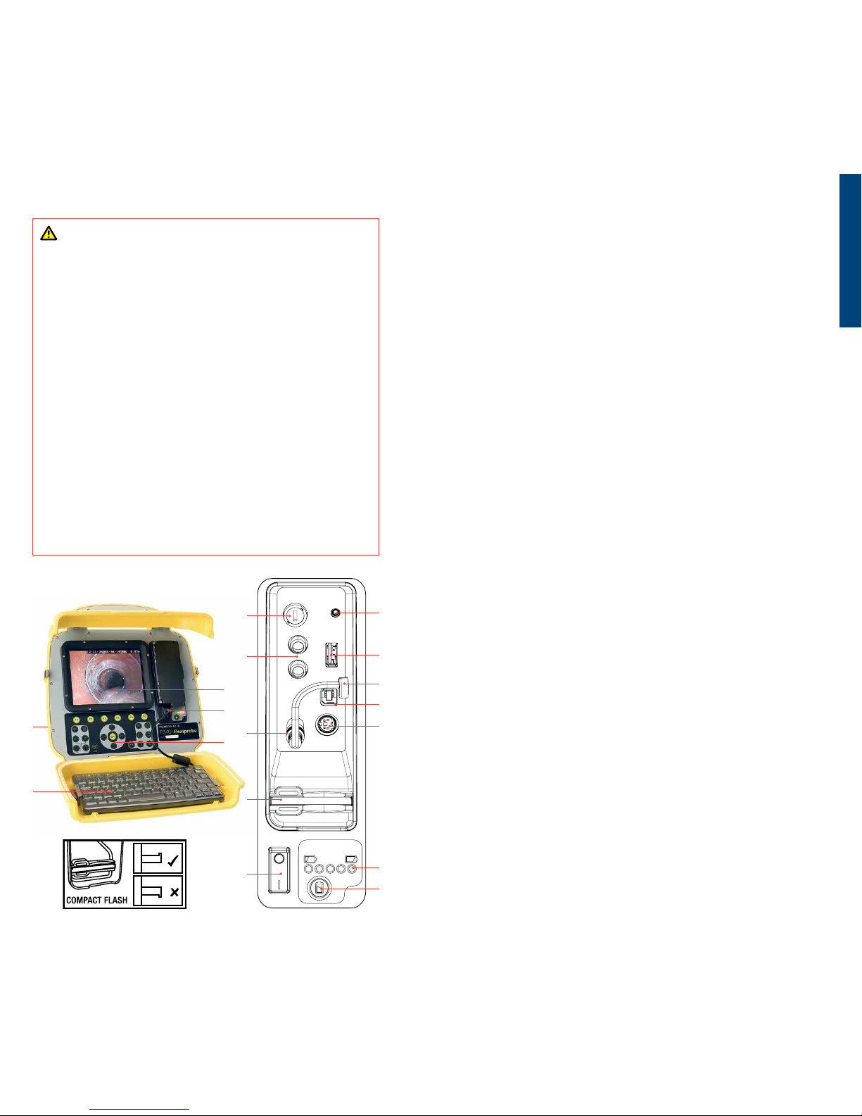
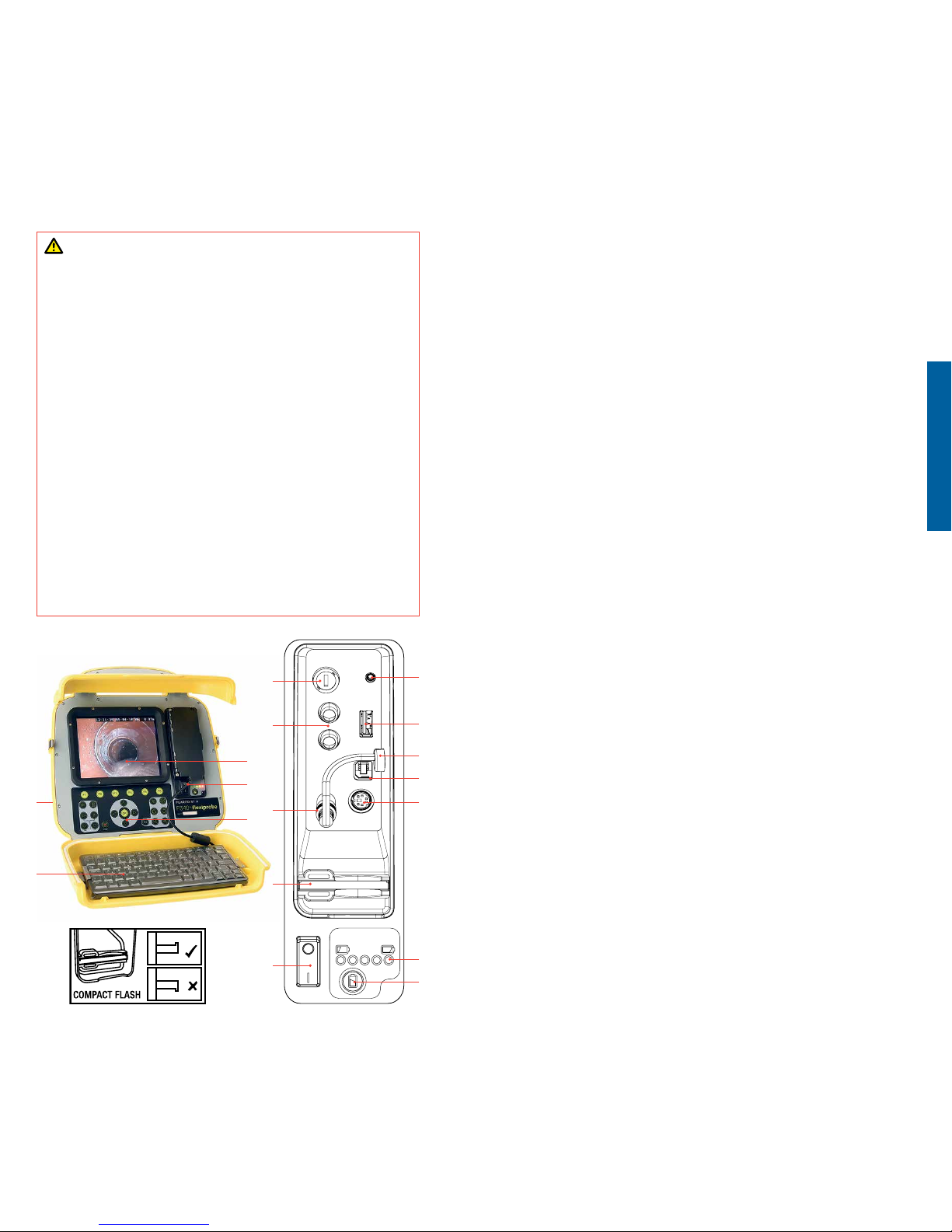
P340 Controller
1 On/O Switch.
2 Keypad and function keys: Allows the operator to select functions
and edit text entries.
3 Keyboard: Provides enhanced text entry capabilities and short-cuts
to access system functions.
4 Display: LCD screen shows image and various on-screen information
such as deployed rod length, operator generated titles, time and date.
5 Link Cable Socket (at rear of unit): Connector for the link cable.
6 Fuse Holder: 5mm x 20mm T3.15A 250V cartridge fuse.
7 RCA Video Jacks: Allows an external composite video source to be
displayed by the P340 controller or recorded onto Compact Flash.
P340 video can also be displayed or recorded on an external device.
8 Power Socket: DC power input from vehicle supply, battery box or
mains adapter.
9 Compact Flash slot: Compact Flash for video recording and later
playback on the controller or PC. Also used for software upgrades
and storing diagnostic log les.
10 Keyboard Socket: Keyboard connector.
11 Audio Socket: Connection for headset using standard 2.5mm
connector.
12 PC socket: Type B USB connection allows le transfers for PC.
13 USB socket: Type A USB connection for USB ash drives. Memory Sticks
can be used for video recording and later playback on the controller or
PC. Also used for software upgrades and storing diagnostic log les.
14 Internal battery power connector and charging plug (P340+ only).
15 Battery Status Indicator (P340+ only). When the Battery Status Check
Button, 16, is pressed, this will display remaining charge. From red lights
only (low charge), to all lights (fully charged).
16 Battery Status Check Button (P340+ only).
ENGLISH
SAFETY WARNINGS
The system is not earthed. If mains operated equipment is connected to
the system then the external equipment must be earthed in accordance
with the manufacturer’s instructions. Failure to comply with this may
cause the unit to become live and be a lethal hazard.
DO NOT USE the P340 exiprobe system in potentially explosive
environments. This equipment is NOT approved for use in hazardous
Locations.
Pushrod reels are heavy. Use the wheels (P342 and P343 models) to assist
transport. Observe heavy-lifting safety practices when lifting the reel.
Foul water systems can be a source of biological hazards. Wear
appropriate protection when handling the P340 controller and the
pushrod reel and camera.
The camera will get hot during use. This is normal. Exercise care when
handling the camera at all times.
The mains power and charging cables are not waterproof and should
only be used in dry environments / indoors. The controller contains an
internal battery for IP53-rated weatherproof operation.
Always use the rod brake to prevent the rod causing damage or injury.
Read the full operation manual for full instructions, available on the CD
and our website.
6
7
8
9
1
11
10
12
13
14
15
16
P340+ controller, with internal
battery power, illustrated

76
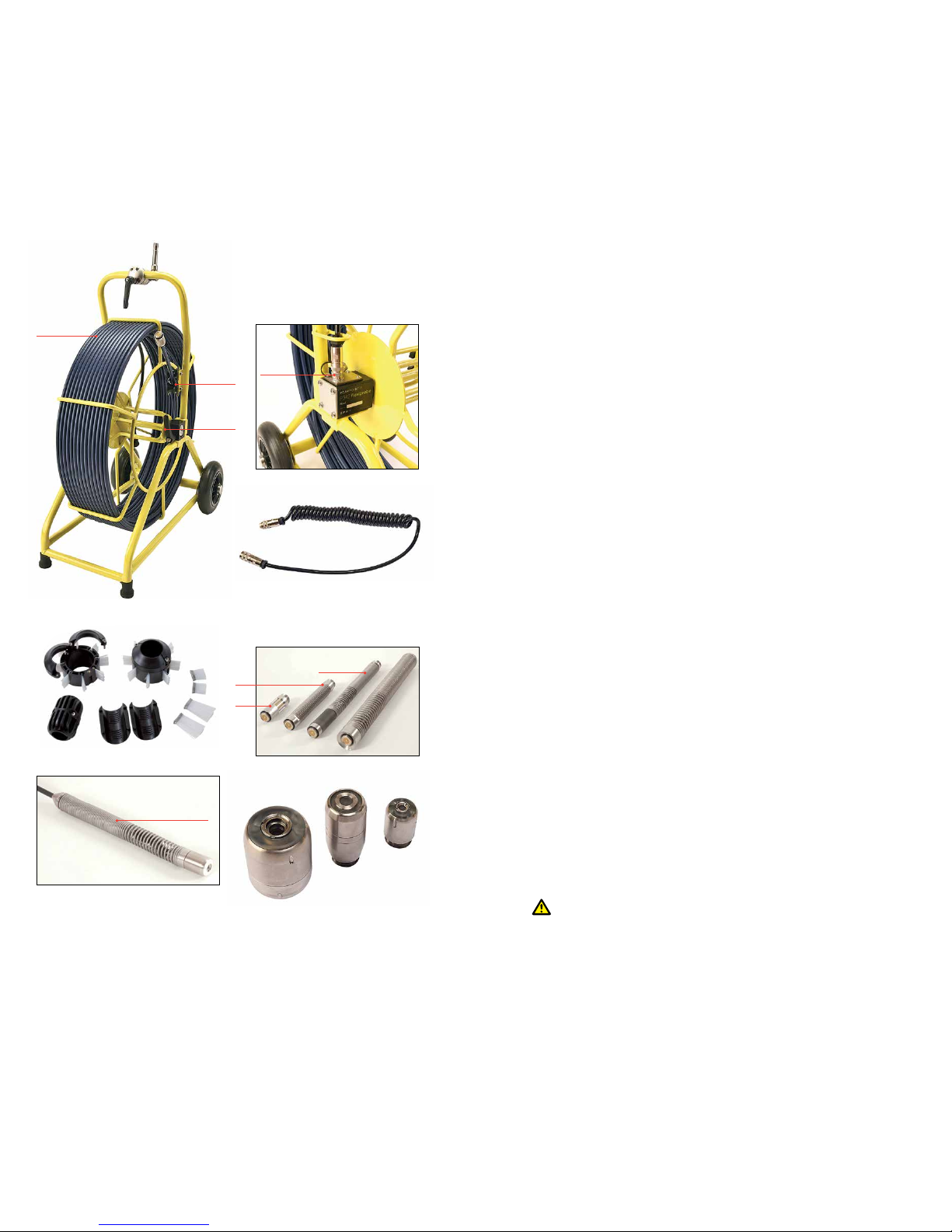
Camera/Pushrod reel
1 Pushrod Reel: Holds the pushrod on a revolving reel. The pushrod is up
to 150m (500ft) in length.
2 Rod Guide: Guides the rod on and o the reel.
3 Cable Socket: Connector for the link cable.
4 Link Cable: To connect the reel to the controller.
5 Skids: Protect the camera during use and centers the camera in the pipe.
Refer to the operation manual for skid and brush installation.
6 Universal Flexi: Attaches to the end of the pushrod to allow the camera
to negotiate small radius bends.
7 Sonde (7a), flexisondes (7b) and non-detachable Plumbers sonde (7c)
(P341 Plumbers reel only): transmit a signal to allow the position
of the camera to be pinpointed using an RD7100
™
DL receiver
(optional purchase).
8 Camera: Three color camera options are available:
a. 50mm (2”) diameter self-levelling camera for up to 230mm (9”)
diameter pipes.
b. 25mm (1”) diameter camera for up to 100mm (4”) diameter pipes.
c. 32mm (1.23”) self-levelling camera.
9 Brake: Can be adjusted to control the reel movement or to lock the reel.
Mains adapter (not shown): Connects the controller to mains power.
Vehicle power lead (not shown): Connects the controller to your vehicle
power socket (12-24V).
Battery pack (not shown): Optional battery pack to allow the use of the
system where mains power is not available.
Controller Clamp (not shown): Allows the controller to be mounted
onto the reel (controller clamp optional on the P341 models).
Environmental specications
• Storage Temperature: -4ºF to 176°F / -20 to 80°C
• O perating Temperature: 14ºF to 122°F / -10 to 50°C
• Charging Temperature*: 14ºF to 104ºF / -10ºC to 40ºC
*P340+ only
• IP Ratings:
Controller: IP55 (covers closed)
IP53 (covers open and socket panel closed)
Cameras: IP68 to 330' (100m) /11bar
WARNING: The mains power and charging cables are not waterproof
and should only be used in dry environments / indoors. The controller
contains an internal battery for IP53-rated weatherproof operation.
1
2
3
4
5
9
7a
7b
6
7c
8a
8c
8b

98
Quick start procedure
• Install the controller on top of the reel if desired (optional on the
P341 models).
• With no power on, attach the camera and accessories to the pushrod.
• Connect the link cable to the connectors on the rear of the controller
and on the pushrod reel.
• Ensure a compatible removable storage device, FAT32 formatted, is
loaded into the controller (Compact Flash or USB Flash Drive).
• Connect the power supply to the controller. If using the optional internal
battery, check you have enough power remaining to perform your survey.
• Switch the controller on.
• Press OK to clear the splash screen.
• Calibrate and zero the camera’s position. Press F10 on the keyboard
or
and on the keypad simultaneously.
• Deploy the camera into the pipe as required.
• If required zero the camera’s position by pressing F10 on the keyboard or
press
and on the keypad simultaneously.
• On the keypad, press the
key to record the inspection.
Enter job details if required:
• Review Client Name, Site Address and Survey Start and Finish Survey
references by pressing the
and keys. Press OK to Edit and press
OK, again, to accept the changes.
• On the keypad, press the
key again to start recording the
inspection.
• Press the
key to take screen captures (if required review Client Name,
Site Address and Survey Start and Finish references as described for
video recording).
• Press OK or enter to make an observation.
• To add text to your videos either:
• Press PG UP or PG DN on the keyboard, or
• Press the
key on the keypad, followed by the F1 (EDIT) key
• To pause a recording, press
.
• To stop a recording, press
.
NOTE: Do not extract the removable storage device during recording or
playback. Doing so may corrupt all data on the storage device and crash
the controller.
Setup
Reel
Connect the link cable to the reel socket and to the controller socket and
ensure that the connectors have been tightened.
Power lead
Release the side catches and open the two halves of the cover.
Open the connection panel cover:
1 If required, connect the keyboard to the keyboard socket.
2 Connect the power supply (12 to 24V DC vehicle supply, mains
adaptor or optional battery pack) to the power socket.
3 Insert a suitable Compact Flash Card or USB Flash Drive formatted
as FAT32.
Recommended Camera Focus Settings
You should focus your camera to match the internal diameter of the pipe
you are about to inspect.
With reference to Tables 1 and 2 place your camera at the required distance
from a target object to get optimal image quality.
Use the focus tool provided with your camera to turn the focusing ring
until the target object is in focus.
Table 1
1" (25mm) Camera
Internal Pipe Diameter Target Object
Inches mm Inches mm
1.25 32 3.0 76
1.5 38 3.6 92
2 51 4.8 122
3 76 7.2 183
4 102 9.6 244
Table 2
2" (50mm) Camera
Internal Pipe Diameter Target Object
Inches mm Inches mm
2 51 5.6 142
3 76 8.4 213
4 102 11.2 284
6 152 16.8 427
8 203 22.4 569
9 229 25.2 640

1110
Conguration
Once the system is correctly assembled and connected to a power source,
you may need to congure the controller’s software.
Switch the On/O switch to On.
After 5 seconds the SPX splash screen will be displayed for 5 seconds.
This will be followed by the welcome screen:
• Check that the date and time are correct and that the correct video
standard for your country (PAL or NTSC) is displayed.
• Check that the correct reel size is set.
• If a USB Flash Drive or CF card is present, check that the correct memory
parameters are displayed (if both a USB drive and CF card are present
then only the USB drive parameters will be displayed).
Press OK or Enter to continue.
If required you can set up the correct reel type, date, time and language
as follows:
To navigate through the system software use the keypad or keyboard
function and arrows keys. Use the
key to return to the previous menu.
Use the
and keys to scroll through the various options and press OK
to accept the selection.
Select the correct reel
Select “Menu” (F1 key) to go to the main menu screen, select “Setup” and
press OK.
Select “Reel”, press OK to continue to the Reel Setup Menu.
Use the
or keys to select the correct reel length and type, press OK
to conrm your choice.
Press
to exit the Reel Setup Menu.
Basic Controller Set-up
From the main Setup Menu, select “Controller” and press OK .
Select “Basic Settings” and press OK.
Select the setting you wish to edit and press OK or Enter.
Use the keyboard to modify Time or Date and use the
and keys to
scroll through the various options.
Press OK to accept the new settings.
When all the required settings have been setup, press F6 to exit to the
top-level screen.
TFT Screen Settings
The screen brightness and contrast functions are available on the top
level screen.
Press BRI (F5) to set the Screen Brightness or CONTR (F6) to set the
Screen Contrast.
Use the
and keys to set the desired value and press OK to accept
your settings.
Jobs
By entering information about your current session Client, Site and Survey
the P340 Controller will organize all your recordings (videos or photos)
and observations in Jobs structures. This information will also be used to
generate the nal detailed report (if required) by using FlexiSight manager.
Consult the operational manual for more details.
To start a new job:
Go to the Job browser: from the main Setup Menu, select “Jobs” and press
OK.
Press NEW (F1) and enter Client, Site and Survey details. Press START to start
the new job.
To resume or review an existing job:
Go to the Job browser: from the main Setup Menu, select “Jobs” and press
OK.
Use the
or keys to select the Job you wish to resume or review and
press OK.
Press START (F1) to resume the job,
or:
use the
and keys to select Job details or media (photos or videos),
press OK to review, edit or preview.
Recordings
NOTE: Do not remove or install the removable storage device when the
system is powered and do not switch o the unit while recording. Failure
to comply may damage the removable storage device and /or recordings.
Formatting the removable storage device will delete all the les.
If you are using a USB ash drive device this will automatically be used to
store all your data (videos, photos and observations) even in the presence
of a compatible CF card.
Video recording
Press the key to start recording.
Enter job details if required:
• Review Client Name, Site Address and Survey Start and Finish Survey
references by pressing the
and keys. Press OK to Edit and then
press OK again to accept the changes.
• On the keypad, press the
key again to start recording the
inspection.
Press the
key to pause a recording, press the key or to resume
recording.
Press the
key to nish recording.
Press Fn and
or to pan a zoomed video image.
Press
or to zoom in or out.
Press the rotate keys
or to rotate the video image.
To restore an altered image, simultaneously press both video eects keys
for example
and .

1312
Still pictures
Press the key at anytime to take still pictures.
Enter job details if required:
• Review Client Name, Site Address and Survey Start and Finish Survey
references by pressing the
and keys. Press OK to Edit and then
press OK again to accept the changes.
• On the keypad, press the
key to capture a picture of the screen
in jpeg format.
You can take screen captures in recording, playback and general inspection
modes. Note that screen captures will also record any on-screen text,
excluding the menu.
Video playback and photo review
To browse your Compact Flash card or USB ash drive, press the video
key on the keypad.
The card browser will open; use the
and arrows to navigate to the le
you wish to view and then press OK or video
.
Video Playback or Photo review will begin immediately.
You can pause or stop video playback at anytime using the
or keypad
keys.
You can stop reviewing a photo by pressing the
key or pressing .
To Fast-Forward press the
arrow key during playback. To resume normal
playback speed, press the video
key.
To Rewind press the
arrow key during playback. To resume normal
playback speed, press video
.
During playback, you can adjust the sound volume at anytime by pressing
F1 or F2.
Storing your Jobs onto your PC
If you have used a USB ash drive connect this to a spare USB port of your
PC and go to step 4.
Or:
If you have used a CF card:
1 Switch the controller o.
2 Connect the USB cable to the unit and to your computer.
3 Your computer will recognize the unit as a Mass Storage Device.
4 Start FlexiSight manager.
5 Press the Import Button.
6 Select the Removable Disk in which your Jobs are stored.
7 Press OK.
For more information, please refer to the Operation Manual available in the
FlexiSight Manager CD or to download from the Radiodetection website.
Charging the internal battery (P340+ only)
WARNING: Use of charging equipment other than supplied by
Radiodetection may compromise the safe operation of the equipment.
WARNING: Only connect the charging equipment to the Internal
battery power connector and charging plug, 14 (see diagram on page 4).
Connection to any other equipment may result in damage both to the
charger and the other equipment.
• Disconnect the Internal battery power connector and charging plug, 14,
from the Power Socket, 8 (see diagram on page 4).
• Plug the automotive charger into a vehicle cigarette lighter socket.
Alternatively, if using an optional mains charger, plug that into a mains
socket.
• Connect the output of the charger to the Internal battery power
connector and charging plug
NOTE: You can continue to use the P340+ system while the battery is
charging by connecting a separate power source (vehicle supply or mains
adapter, both supplied with the P340+, or an external battery box option)
to the Power Socket.
Maintenance
Clean and sanitize the P340 exiprobe system at regular intervals and after
conducting an inspection.
The P340 exiprobe system contains no user serviceable parts; do not
dismantle any component of the P340 exiprobe system, including the
controller, reel and camera.
Pearpoint recommends that only authorized service centers carry out
service of this product. Service elsewhere will invalidate the manufacturer’s
warranty.
For information regarding any service needs, please visit:
www.radiodetection.com or contact your local Pearpoint representative
or dealer.
Training
Pearpoint provides training services for most Pearpoint products. Our
qualied instructors will train equipment operators or other personnel
at your preferred location or at Pearpoint headquarters.
For more information go to www.radiodetection.com or contact your
local Pearpoint representative.
1514
2
1
4
3
5
P340 Steuerung
1 Ein-/Aus-Schalter.
2 Tastenfeld und Funktionstasten: Ermöglichen es dem Anwender,
Funktionen auszuwählen und Texteinträge zu bearbeiten.
3 Tastatur: Bietet erweiterte Texteingabemöglichkeiten und
Tastaturbefehle für den Zugri auf Systemfunktionen.
4 Display: Der LCD-Bildschirm zeigt Bilder und verschiedene
Bildschirminformationen, wie z. B. verwendete Schubkabellänge, vom
Anwender generierte Titel, Uhrzeit und Datum.
5 Verbindungskabelstecker (an der Rückseite der Einheit):
Steckverbinder für Verbindungskabel.
6 Sicherungshalter: 5 mm x 20 mm, T, 3,15 A, 250 V Sicherungseinsatz.
7 Cinch (RCA) Videostecker: Ermöglicht die Ansicht einer externen
Composite-Video-Quelle über die P340 Steuerung oder von einer
CompactFlash-Speicherkarte. Ein P340 Video kann ebenfalls auf einem
externen Gerät angezeigt oder gespeichert werden.
8 Netzsteckdose: DC-Stromzufuhr aus der Bordnetzversorgung,
Batteriekasten oder Netzteil.
9 CompactFlash-Steckplatz: CompactFlash-Speicherkarte zur
Speicherung und späteren Wiedergabe von Videoaufnahmen über
die Steuerung oder den PC. Wird auch für Softwareupgrades und zur
Speicherung von Diagnoseprotokolldateien verwendet.
10 Tastaturanschluss: Tastatursteckverbinder.
11 Audioanschluss: Anschluss für Headset mithilfe eines 2,5-mm-
Standardbananensteckers.
12 PC-Anschluss: Typ B USB-Verbindung ermöglicht die Übertragung von
Dateien.
13 USB-Anschluss: Typ A USB-Verbindung für USB-Speichersticks.
Speichersticks können zur Speicherung und späteren Wiedergabe
von Videoaufnahmen über die Steuerung oder den PC verwendet
werden. Wird auch für Softwareupgrades und zur Speicherung von
Diagnoseprotokolldateien verwendet.
14 Stromanschluss und Ladestecker für internen Akku (nur P340+).
15 Akkuladeanzeige (nur P340+). Zeigt die verbleibende Akkuladung an,
wenn die Kontrolltaste Akkuladung, 16, gedrückt wird. Ladungsanzeige
reicht von Ladung schwach (nur rote Lämpchen leuchten) bis
vollgeladen (alle Lämpchen leuchten).
16 Kontrolltaste Akkuladung (nur P340+).
DEUTSCH
SICHERHEITSHINWEISE
Das System ist nicht geerdet. Falls strombetriebene Ausrüstung an das
System angeschlossen wird, muss die externe Ausrüstung im Einklang mit
den Herstelleranweisungen geerdet werden. Eine Nichteinhaltung dieser
Anweisungen kann dazu führen, dass das Gerät stromführend und zu
einer tödlichen Gefahr wird.
BENUTZEN Sie das P340 exiprobe System NICHT in potenziell explosiven
Umgebungen. Diese Ausrüstung besitzt KEINE Genehmigung für die
Nutzung in Bereichen, in denen gefährliche Gase vorhanden sein können.
Die Schubkabeltrommeln sind schwer. Benutzen Sie die Rollen (Modelle
P342 und P343) zur Unterstützung beim Transport. Beachten Sie
Sicherheitsübungen zum Heben schwerer Gegenständer beim Anheben
der Kabeltrommel.
Abwassersysteme können eine Quelle für biologische Gefahren
darstellen. Tragen Sie angemessene Schutzkleidung, wenn Sie die P340Steuerung und die Schubkabeltrommel sowie die Kamera verwenden.
Die Kamera wird während des Gebrauchs heiß. Dies ist normal. Gehen Sie
immer beim Gebrauch der Kamera umsichtig vor.
Netz- und Ladekabel sind nicht wasserdicht und sollten nur in trockener
Umgebung / im Haus verwendet werden. Die im Controller eingebaute
Batterie erlaubt Arbeiten unter Umgebungsbedingungen nach IP53.
Benutzen Sie stets die Bremse um Beschädigungen oder Verletzungen
durch das Schiebekabel zu vermeiden.
Beachten Sie die vollständige Gebrauchsanleitung, erhältlich auf der
beiliegenden CD und unserer Website.
6
7
8
9
1
11
10
12
13
14
15
16
Abgebildet: Steuerung P340+
mit internem Akku
1716
3 Kabelanschluss: Steckverbinder für Verbindungskabel.
4 Verbindungskabel: Zur Verbindung des Verbindungskabels mit der
Steuerung.
5 Gestelle: Schützen die Kamera während der Anwendung und zentrieren
die Kamera im Rohr. Lesen Sie bitte die Bedienungsanleitung zur
Rahmen- und Bürsteninstallation.
6 Universalanschlusskabel: Wird am Ende des Schubkabels angebracht,
damit die Kamera kleine Biegeradien durchfahren kann.
7 Sonde (7a), Kabelsonden (7b) und nicht abnehmbare
Installateursonden (7c) (nur P341 Kabeltrommel für Installateure):
Senden ein Signal, über das die Position der Kamera mithilfe des
Empfängers RD7100
™
DL (auf Wunsch erhältlich) punktgenau geortet
werden kann.
8 Kamera: Drei Farbkamera-Ausführungen sind erhältlich:
a. 50-mm-Selbstnivellierende Kamera für Rohrleitungen mit einem
Durchmesser von bis zu 230 mm.
b. 25-mm-Kamera für Rohrleitungen mit einem Durchmesser von bis
zu 100 mm.
c. 32-mm Selbstnivellierende Kamera.
9 Bremse: Kann eingestellt werden, um die Bewegung der Kabeltrommel
zu steuern oder um die Kabeltrommel zu sperren.
Netzteil (nicht abgebildet): Verbindet die Steuerung mit dem
Stromnetz.
Fahrzeugstromkabel (nicht abgebildet): Verbindet die Steuerung mit
dem Stromanschluss Ihres Fahrzeugs (12-24 V).
Akku (nicht abgebildet): Optionaler Akku, um einen Einsatz des
Systems auch dort zu ermöglichen, wo kein Anschluss an ein Stromnetz
vorhanden ist.
Steuerungsklemme (nicht abgebildet): Damit kann die Steuerung an
der Kabeltrommel befestigt werden (Steuerungsklemmen auf Wunsch
für P341-Modelle erhältlich).
Umgebungsdaten
• Lagerungstemperatur: -20 °C bis 80 °C
• Betriebstemperatur: -10 °C bis 50 °C
• Ladetemperatur*: -10 °C bis 40 °C
*nur P340+
• IP-Schutzklasse:
Steuerung: IP55 (geschlossene Abdeckungen)
IP53 (geönete Abdeckungen und geschlossene Anschlussleiste)
Kameras: Schutzklasse IP68 bis 100 m / 11 bar
WARNUNG: Netz- und Ladekabel sind nicht wasserdicht und sollten
nur in trockener Umgebung / im Haus verwendet werden. Die im Controller
eingebaute Batterie erlaubt Arbeiten unter Umgebungsbedingungen nach
IP53.
Kamera/Schubkabeltrommel
1 Schubkabeltrommel: Hält das Schubkabel auf einer Drehtrommel.
Das Schubkabel hat eine Länge von bis zu 150 m.
2 Schubkabelführung: Führt das Schubkabel auf die und von der
Kabeltrommel.
1
2
3
4
5
9
7a
7b
6
7c
8a
8c
8b

1918
Schnellstartverfahren
• Installieren Sie die Steuerung, falls gewünscht, oben auf der
Kamerakabeltrommel (optional bei P341-Modellen).
• Schließen Sie die Kamera und das Zubehör nur bei ausgeschaltetem
Gerät an das Schubkabel an.
• Verbinden Sie das Verbindungskabel mit den Steckverbindern auf der
Rückseite der Steuerung und an der Schubkabeltrommel.
• Stellen Sie sicher, dass eine kompatible, abnehmbare
Speichervorrichtung, die FAT32-formatiert ist, in die Steuerung
eingesetzt ist (CompactFlash-Speicherkarte oder USB-Speicherstick).
• Schließen Sie die Steuerung an die Stromzufuhr an. Kontrollieren Sie
bei Verwendung des optionalen internen Akkus, ob der Akku für die
Durchführung der Ortung ausreichend aufgeladen ist.
• Schalten Sie die Steuerung ein.
• Drücken Sie auf OK, um den Logobildschirm zu entfernen.
• Kalibrieren Sie die Position der Kamera und stellen Sie sie auf den
Nullpunkt ein. Drücken Sie auf die Funktionstaste F10 auf der Tastatur
oder gleichzeitig auf die Tasten
und auf dem Tastenfeld.
• Setzen Sie die Kamera wie benötigt in das Rohr ein.
• Stellen Sie die Kameraposition bei Bedarf auf null. Dazu drücken Sie die
Funktionstaste F10 auf der Tastatur oder gleichzeitig die Tasten
und
auf dem Tastenfeld.
• Drücken Sie dann auf dem Tastenfeld die Taste
, um die Inspektion
aufzuzeichnen.
Geben Sie nach Bedarf die Aufgabendetails ein:
• Überprüfen Sie Ihre Angaben zu Kundenname, Standortadresse und
Inspektionsbeginn und -ende mithilfe der Tasten
und . Drücken
Sie auf OK, um die Angaben zu bearbeiten, und dann erneut auf OK,
um die Änderungen zu übernehmen.
• Drücken Sie dann auf dem Tastenfeld die Taste
, um mit der
Inspektionsaufzeichnung zu beginnen.
• Drücken Sie auf die Taste
, um Screenshots anzufertigen (überprüfen
Sie bei Bedarf Ihre Angaben zu Kundenname, Standortadresse und
Inspektionsbeginn und -ende, wie unter Videoaufzeichnung dargelegt).
• Drücken Sie auf die Taste OK oder Enter (Eingabe), um Beobachtungen
einzugeben.
• Wenn Sie Ihren Videos Text hinzufügen möchten:
• Drücken Sie die Tasten PG UP oder PG DN auf der Tastatur oder
• Drücken Sie die Taste
auf dem Tastenfeld und dann die Taste F1
(EDIT)
• Um eine Aufzeichnung zu unterbrechen, drücken Sie auf die Taste
.
• Um eine Aufzeichnung zu beenden, drücken Sie auf die Taste
.
HINWEIS: Entfernen Sie Wechselspeichermedien nicht während einer
Aufzeichnung oder Wiedergabe einer Aufnahme. Dies kann alle auf dem
Speichermedium bendlichen Daten beschädigen und die Steuerung
zum Absturz bringen.
Einrichtung
Kabeltrommel
Verbinden Sie das Verbindungskabel auf der Kabeltrommel mit dem
Anschluss auf der Rückseite der Steuerung und stellen Sie sicher, dass alle
Steckverbinder fest sitzen.
Netzanschlusskabel
Lösen Sie die Seitenbefestigungen und önen Sie die zwei Abdeckungshälften.
Önen Sie die Anschlussabdeckung:
1 Verbinden Sie bei Bedarf die Tastatur mit dem Tastaturanschluss.
2 Verbinden Sie die Stromversorgung (12 bis 24 VDC Bordanschluss,
Netzteil oder optionaler Akku) mit der Strombuchse.
3 Stecken Sie eine geeignete FAT32-formatierte CompactFlash-
Speicherkarte oder einen entsprechenden USB-Speicherstick ein.
Empfohlene Einstellungen des Kamerafokus
Sie müssen den Fokus Ihrer Kamera passend zum Innendurchmesser der
Rohrleitung einstellen, die inspiziert werden soll.
Platzieren Sie Ihre Kamera gemäß den Angaben in Tabelle 1 und 2 im
erforderlichen Abstand zum Zielobjekt, um eine optimale Bildqualität zu erhalten.
Verwenden Sie das Fokussierwerkzeug, das im Lieferumfang Ihrer Kamera
enthalten ist, um den Fokussierring so lange zu drehen, bis das Zielobjekt
scharf eingestellt ist.
Tabelle 1
25-mm-Kamera
Innenrohrdurchmesser Zielobjekt
mm mm
32 76
38 92
51 122
76 183
102 244
Tabelle 2
50-mm-Kamera
Innenrohrdurchmesser Zielobjekt
mm mm
51 142
76 213
102 284
152 427
203 569
229 640
 Loading...