

Page 1

CYCLONE FX Programmers
User Manual
Page 2

Purchase Agreement
P&E Microcomputer Systems, Inc. reserves the right to make changes without further notice to any products herein to improve reliability, function, or
design. P&E Microcomputer Systems, Inc. does not assume any liability arising out of the application or use of any product or circuit described herein.
This software and accompanying documentation are protected by United States Copyright law and also by International Treaty provisions. Any use of this
software in violation of copyright law or the terms of this agreement will be prosecuted.
All the software described in this document is copyrighted by P&E Microcomputer Systems, Inc. Copyright notices have been included in the software.
P&E Microcomputer Systems authorizes you to make archival copies of the software and documentation for the sole purpose of back-up and protecting
your investment from loss. Under no circumstances may you copy this software or documentation for the purpose of distribution to others. Under no
conditions may you remove the copyright notices from this software or documentation.
This software may be used by one person on as many computers as that person uses, provided that the software is never used on two computers at the
same time. P&E expects that group programming projects making use of this software will purchase a copy of the software and documentation for each
user in the group. Contact P&E for volume discounts and site licensing agreements.
P&E Microcomputer Systems does not assume any liability for the use of this software beyond the original purchase price of the software. In no event will
P&E Microcomputer Systems be liable for additional damages, including any lost profits, lost savings or other incidental or consequential damages arising
out of the use or inability to use these programs, even if P&E Microcomputer Systems has been advised of the possibility of such damage.
By using this software, you accept the terms of this agreement.
©2015-2018 P&E Microcomputer Systems, Inc.
ARM and Cortex are registered trademarksof ARM Ltd. or its subsidiaries.
NXP, ColdFire, and Kinetis are registered trademarks of NXP Semiconductors.
Texas Instruments and TI are registered trademarks of Texas Instruments Incorporated.
STMicroelectronics is a registered trademark of STMicroelectronics, Inc.
All other product or service names are the property of their respective owners.
P&E Microcomputer Systems, Inc.
98 Galen St.
Watertown, MA 02472
617-923-0053
http://www.pemicro.com
Manual version: 1.13
November 2018
Page 3

1 INTRODUCTION.........................................................................................................................................1
2 QUICK START GUIDE FOR SAP OPERATION.........................................................................................2
3 CYCLONE
3.1 Touchscreen LCD ...........................................................................................................................................5
3.2 LED Indicators.................................................................................................................................................5
3.3 Start Button .....................................................................................................................................................5
3.4 Access Panel...................................................................................................................................................5
3.5 Cyclone System Power ...................................................................................................................................6
3.6 RS232 Communication (Serial Port) ...............................................................................................................6
3.7 Ethernet Communication.................................................................................................................................6
3.8 USB Communications .....................................................................................................................................6
3.9 Electromechanical Relays ...............................................................................................................................6
3.10 Power Connectors...........................................................................................................................................7
3.11 Reset Button....................................................................................................................................................7
3.12 SDHC Port.......................................................................................................................................................7
3.13 Control Expansion Port ...................................................................................................................................8
3.14 Optional Oscillator (MON08 Only)...................................................................................................................8
3.15 Cyclone Time / Real Time Clock .....................................................................................................................8
3.16 Power Jumper Settings ...................................................................................................................................8
3.17 Debug Connectors ..........................................................................................................................................8
3.18 Target Headers For Part# CYCLONE_ACP_FX...........................................................................................10
3.19 Target Headers For Part# CYCLONE_UNIVERSAL_FX .............................................................................13
3.20 Ribbon Cable.................................................................................................................................................20
FX HARDWARE........................................................................................................................5
4 TARGET POWER MANAGEMENT ..........................................................................................................21
4.1 Cyclone Configuration ...................................................................................................................................21
4.2 Cyclone Setup ...............................................................................................................................................23
4.3 Setup Reminders...........................................................................................................................................25
5 TOUCHSCREEN LCD MENU...................................................................................................................26
5.1 Home Screen ................................................................................................................................................26
5.2 Main Menu.....................................................................................................................................................27
6 CREATING PROGRAMMING IMAGES....................................................................................................34
6.1 Create A Stand-Alone Programming (SAP) Image .......................................................................................34
6.2 Manage Multiple SAP Images .......................................................................................................................44
7 CYCLONE PROGRAMMER MANUAL CONTROL...................................................................................46
7.1 Operation Via Start Button ............................................................................................................................46
7.2 Operation Via LCD Touchscreen Menu ........................................................................................................47
7.3 Home Screen ................................................................................................................................................47
7.4 Status Window ..............................................................................................................................................48
8 CYCLONE PROGRAMMER AUTOMATED CONTROL (CYCLONE CONTROL SUITE) ........................50
Page 4

8.1 Overview Of Cyclone Control Suite...............................................................................................................50
8.2 Cyclone Control SDK ....................................................................................................................................51
8.3 Cyclone Control Console...............................................................................................................................69
8.4 Cyclone Control GUI .....................................................................................................................................72
8.5 License ..........................................................................................................................................................78
9 SAP IMAGE COMPILER (SCRIPTED PROGRAMMING & IMAGE CREATION)..................................... 80
9.1 Launching From the Command Line .............................................................................................................80
9.2 Configuration (.CFG) File Contents...............................................................................................................82
9.3 CSAP Error Returns ......................................................................................................................................90
10 ETHERNET CONFIGURATION................................................................................................................93
10.1 Network Architectures ...................................................................................................................................93
10.2 Network Parameters......................................................................................................................................93
10.3 Internet Protocol ............................................................................................................................................94
10.4 Connecting The Cyclone Device ...................................................................................................................94
10.5 Cyclone IP Setup Via LCD Menu ..................................................................................................................95
10.6 Configuring Cyclone Network Settings using the Cyclone Control GUI ........................................................96
11 USING A BARCODE SCANNER TO SELECT AN IMAGE & INITIATE PROGRAMMING ......................99
11.1 Introduction....................................................................................................................................................99
11.2 Scanning Procedure......................................................................................................................................99
11.3 Potential Benefits Of Programming Via Barcode Scan ...............................................................................100
11.4 Enabling Barcode Scanner In Cyclone Menu..............................................................................................101
11.5 Creating A Barcode Test: Quick Example...................................................................................................101
11.6 Creating a Barcode Test: In Depth..............................................................................................................104
11.7 Adding A Barcode Test Into A Programming Image ...................................................................................119
11.8 Troubleshooting...........................................................................................................................................120
12 AUTOMATIC SERIAL NUMBER MECHANISM......................................................................................122
12.1 Understanding Serialization ........................................................................................................................122
12.2 Serialize Utility.............................................................................................................................................122
12.3 Changing Serial Number Format to Little-Endian........................................................................................124
12.4 Serialize Utility Example..............................................................................................................................125
12.5 Using Serial Number File ............................................................................................................................125
12.6 Serial Number Handling ..............................................................................................................................125
13 TROUBLESHOOTING ............................................................................................................................127
13.1 My Cyclone Is Non-Responsive, Is There A Way I Can Try To Re-Activate It?..........................................127
13.2 I Received An Error When Using A Next-Gen Cyclone Saying That My SAP Image Needs To Be Updated,
How Do I Do This? ......................................................................................................................................127
13.3 When Trying To Install The CYCLONE Software, A Popup WDREG Error Occurs Telling Me That There Are
Open Devices Using WinDriver...................................................................................................................128
14 ERROR CODES......................................................................................................................................129
14.1 Debug Mode Communication Related Errors..............................................................................................129
Page 5

14.2 SAP Image Handling Related Errors...........................................................................................................129
14.3 SAP Algorithm header Operation Handling Related Errors.........................................................................129
14.4 SAP Operation Related Errors ....................................................................................................................130
14.5 SAP Blank Check Range and Module Related Errors ................................................................................130
14.6 SAP Erase Range and Module Related Errors ...........................................................................................130
14.7 SAP Program Byte, Word, and Module Related Errors...............................................................................130
14.8 SAP Verify Checksum Related Errors.........................................................................................................131
14.9 SAP Verify Range and Module Related Errors ...........................................................................................131
14.10 SAP User Function Related Errors..............................................................................................................131
14.11 SAP Trim Related Errors.............................................................................................................................131
14.12 Unrecoverable Fatal Errors .........................................................................................................................131
14.13 Operation Security Related Errors ..............................................................................................................132
14.14 External Memory-Related Errors.................................................................................................................132
14.15 Serial Number Related Errors .....................................................................................................................132
14.16 Download Count Related Errors..................................................................................................................133
14.17 System Hardware/Firmware/Logic Recoverable Errors ..............................................................................133
14.18 Barcode Scanner Errors..............................................................................................................................133
15 TECHNICAL INFORMATION..................................................................................................................134
15.1 Life Expectancy ...........................................................................................................................................134
15.2 Electrical Specifications...............................................................................................................................134
15.3 Mechanical Specifications ...........................................................................................................................134
15.4 Electromechanical Relays ...........................................................................................................................134
15.5 Debug Ports - CYCLONE_ACP_FX ...........................................................................................................134
15.6 Debug Ports - CYCLONE_UNIVERSAL_FX ..............................................................................................134
15.7 International Shipping..................................................................................................................................134
15.8 Compliances/Standards ..............................................................................................................................134
Page 6
1 INTRODUCTION
PEmicro's CYCLONE FX production programmers are powerful, fast, and feature rich in-circuit
programming solutions. PEmicro offers two models which have the same feature set and only vary
by the devices supported.
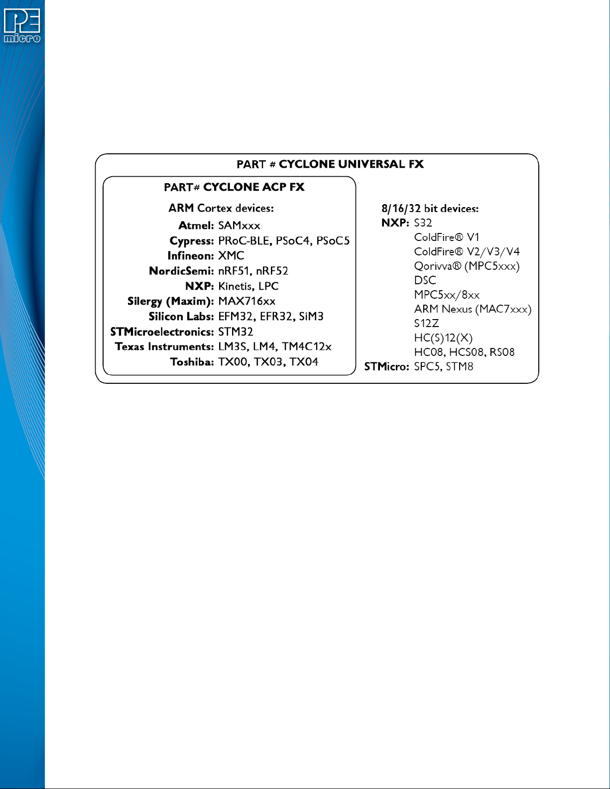
The CYCLONE_ACP_FX supports a wide variety of ARM Cortex devices.
The CYCLONE_UNIVERSAL_FX supports those ARM Cortex devices as well as the following
NXP device families: Kinetis, LPC, S32, Qorivva (MPC5xxx), MPC5xx/8xx, DSC, S12Z, RS08,
S08, HC08, HC(S)12(X), ColdFire, and STMicroelectronics’ SPC5 & STM8.
Figure 1-1: CYCLONE FX Supported Architectures
CYCLONE FX programmers are designed to withstand the demands of a production environment.
They are Stand-Alone Programmers (SAP) that can be operated manually or used to host
automated programming. In manual SAP mode the Cyclone is operated using the touchscreen
LCD Menu and/or the Start button. Host-controlled SAP mode, for automated programming, is
accomplished using the Cyclone Control Suite. See CHAPTER 8 - CYCLONE PROGRAMMER
AUTOMATED CONTROL (CYCLONE CONTROL SUITE)..
User Manual For CYCLONE FX Programmers 1
Page 7

2 QUICK START GUIDE FOR SAP OPERATION
Stand-Alone Programming (SAP) is the most common use of the CYCLONE FX. This quick-start
guide illustrates how easy it is to begin using the Cyclone for stand-alone programming.
You are encouraged to read this manual in its entirety for a complete description of all features
specific to your Cyclone, many of which are beyond the scope of this quick-start guide.
Step 1. Install Software
The first step is to install the accompanying software. This will install all of the applications and
drivers that can be used to configure/control the CYCLONE FX.
Once the installation is complete and the PC has been rebooted you may begin to configure the
Cyclone for SAP operation.
Step 2. Hardware Setup
a. Configure the target power management scheme
Power management is configured by setting jumpers that are revealed by opening the
access panel on the Cyclone’s left side. The corresponding settings are conveniently
illustrated on the rear label of Cyclone. No jumpers are installed by default. You may
wish to refer to CHAPTER 4 - TARGET POWER MANAGEMENT.
b. Connect the Cyclone to your PC
Select the appropriate communications interface (Serial, USB or Ethernet) and
connect the Cyclone to your PC. If you wish to use the Ethernet port you will need to
configure the corresponding network settings before use, either through the
touchscreen LCD menu or via the software utility ConfigureIP. The Ethernet port will
not function properly until this configuration is complete. You may wish to refer to
Section 8.5.1 - Hardware Licensing.
c. Power up the Cyclone.
Step 3. Create a SAP Image
A SAP image, or Stand-Alone Programming image, is a self-sufficient data object containing the
Cyclone and target hardware setup information, programming algorithm, programming sequence,
and target data. The Cyclone uses these images to perform SAP operations on target devices.
Follow these steps to create a SAP image:
a. Run the Cyclone Image Creation Utility (CreateImage.exe)
This utility is a GUI designed to help users create architecture/manufacturer-specific
SAP images. To run this utility:
From the “Start” menu of your PC, select All Programs. From there, select “PEmicro
Cyclone Programmer”, then select -> Cyclone Image Creation Utility. The utility is
shown in Figure 2-1. Continue with the steps below to create an image.
User Manual For CYCLONE FX Programmers 2
Page 8
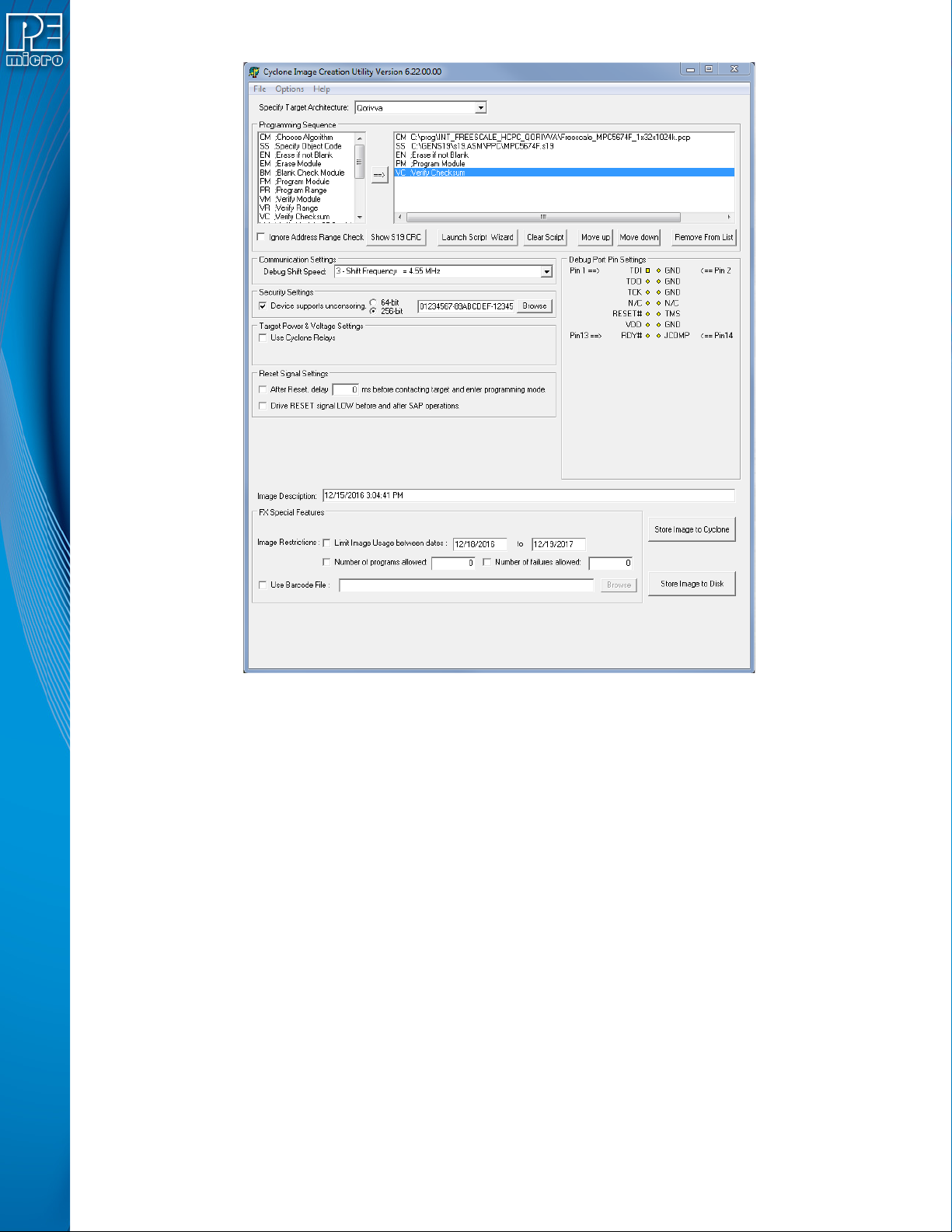
Figure 2-1: Cyclone Image Creation Utility (Qorivva Selected)
b. In the Cyclone Image Creation Utility, select your CPU manufacturer and architecture
from their respective drop-down lists.
c. Click the “Launch Script Wizard” button. Follow the pop-up screens to specify a pro-
gramming algorithm and target object file. The programming algorithm, target object
file, and default programming sequence will then show up in the programming
sequence listbox.
d. Specify the auxiliary setup and hardware setup, such as Communication Mode, Com-
munication Rate, Target Power, and Voltage Settings.
e. Type an Image Description for your SAP image. The default description is a time
stamp.
f. Click the “Store Image to Cyclone” button.
g. The Cyclone Control GUI will pop up. Use the drop-down box to select the Cyclone to
which the image will be saved, then click the “Connect” button. Finally click "Apply
Changes" and the image information will be stored on the Cyclone you selected. Your
SAP image has now been created.
Step 4. Execute SAP Image
The SAP image stored on your Cyclone can now be programmed to the target with one button
press. Once your target is connected to the Cyclone, press the “Start” button of the Cyclone unit
and wait for programming operations to finish. During this process, the LCD screen will show the
status of operations. Note that the menu option described in Section 5.2.3.5.3 - Set Progress
User Manual For CYCLONE FX Programmers 3
Page 9

Details will allow you to set the Cyclone to display either more or less detailed information about
the programming process during programming. Eventually the “Success” or “Error” LED will
illuminate, and the LCD screen will display the results.
Note: If programming is unsuccessful when using this quick start setup, the user may instead wish to use
the included PROG software for their device. The PROG software allows the user to manually walk
through the programming procedure step by step, which may help determine which part of setup or
programming function is causing difficulty.
User Manual For CYCLONE FX Programmers 4
Page 10
3 CYCLONE FX HARDWARE
The following is an overview of the features and interfaces of the CYCLONE FX programmers.
Many of these interfaces are labeled on the underside of the plastic case.
3.1 Touchscreen LCD
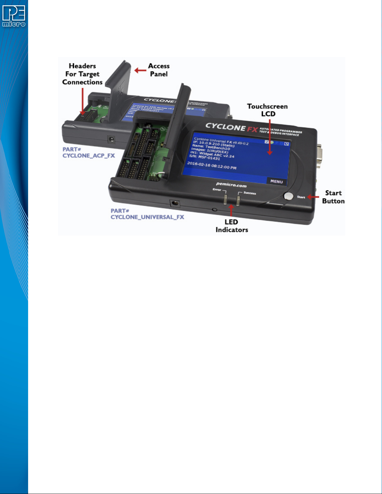
The LCD Touchscreen displays information about the Cyclone’s configuration and the
programming process, and also allows the user to navigate the Cyclone’s menus. The location of
the Touchscreen LCD is shown in Figure 3-1.
3.2 LED Indicators
The LED indicators for Error or Success will illuminate depending on the results of the
programming process and provide a clear visual indication of the results. The location of the LED
Indicators is shown in Figure 3-1.
3.3 Start Button
The Start Button can be used to begin the programming process manually, provided that the
Cyclone is properly configured. The location of the Start Button is shown in Figure 3-1.
3.4 Access Panel
The Access Panel can easily be opened to allow the user to connect/disconnect ribbon cables
from the headers, or to configure the Cyclone’s Power Jumpers to select one of the available
Power Management setups. The location of the Access Panel is shown in Figure 3-1; a layout of
the headers and jumpers beneath the Access Panel is shown in Figure 3-5.
Figure 3-1: CYCLONE FX Top View
User Manual For CYCLONE FX Programmers 5
Page 11
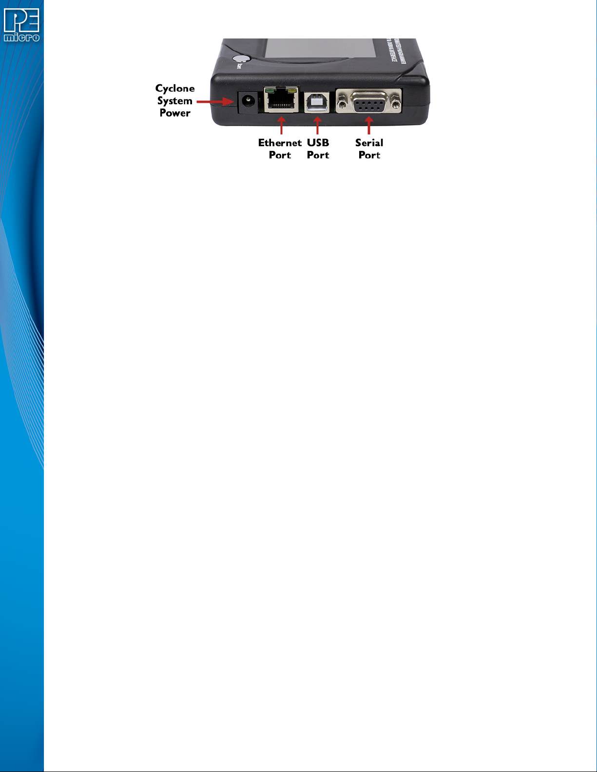
Figure 3-2: CYCLONE FX Right Side View
3.5 Cyclone System Power
The CYCLONE FX programmer requires a regulated 6V DC Center Positive power supply with
2.5/5.5mm female plug. Cyclones derive power from the Power Jack located on the right end of the
unit. The location of Cyclone System Power is shown in Figure 3-2.
3.6 RS232 Communication (Serial Port)
The CYCLONE FX provides a DB9 Female connector to communicate with a host computer
through the RS232 communication (115200 Baud, 8 Data bits, No parity, 1 Stop bit). The location
of the Serial Port is shown in Figure 3-2.
3.7 Ethernet Communication
The CYCLONE FX provides a standard RJ45 socket to communicate with a host computer
through the Ethernet Port (10/100 BaseT). The location of the Ethernet Port is shown in Figure 3-
2.
3.8 USB Communications
The CYCLONE FX provides a USB connector for Universal Serial Bus communications between
the Cyclone and the host computer. The CYCLONE FX is a USB 2.0 Full-Speed compliant device.
The location of the USB Port is shown in Figure 3-2.
3.9 Electromechanical Relays
Inside the CYCLONE FX programmer, two electromechanical relays are used to cycle target
power. The specifications of the relays are as following:
Maximum switched power: 30W or 125 VA
Maximum switched current: 1A
Maximum switched voltage: 150VDC or 300VAC
UL Rating: 1A at 30 VDC
1A at 125 VAC
PEmicro only recommends switching DC voltages up to 24 Volts.
User Manual For CYCLONE FX Programmers 6
Page 12
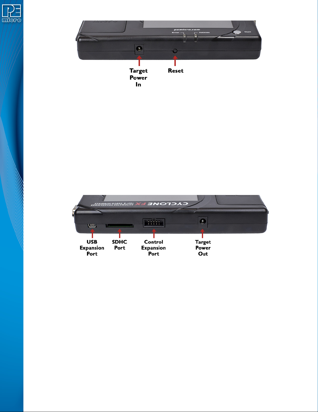
3.10 Power Connectors
The CYCLONE FX programmers provide a Target Power Supply Input Jack and a Target Power
Supply Output Jack with 2.5/5.5 mm Pin Diameter. The power jacks are connected or
disconnected by two electromechanical relays. When connected, the Center Pin of the Target
Power Supply Input Jack is connected to the Center Pin of the Target Power Supply Output Jack.
When disconnected, both terminals of the Target Power Supply Output Jack are connected to
GND via a 1W, 100 Ohm resistor. The location of Target Power In is shown in Figure 3-3, and the
location of Target Power Out is shown in Figure 3-3.
3.11 Reset Button
The Reset Button performs a hard reset of the Cyclone system. The location of the Reset Button is
shown in Figure 3-3.
Figure 3-3: CYCLONE FX Front Side View
Figure 3-4: CYCLONE FX Rear Side View
3.12 SDHC Port
Note: The SDHC port is activated on all CYCLONE FX programmers, and may be activated on
CYCLONE programmers via purchase of the SDHC Activation License.
The SDHC port allows the user to store programming images that are, individually or collectively,
larger than the Cyclone’s internal memory. It also makes it quicker and more convenient to swap
programming images. PEmicro offers certified SDHC cards on our website at pemicro.com.
Cyclone programmers support up to a 4GB SDHC card, at minimum. The location of the SDHC
Port is shown in Figure 3-3.
Programming images are managed on the SD card in exactly the same way as they are in the
Cyclone’s internal memory. Please see Section 6.2 - Manage Multiple SAP Images for more
information about using the Manage Images utility.
To view detailed information about the status of the SDHC card/port, tap the icon bar at the top of
the touchscreen menu. This status can provide you with relevant information if you are
encountering any difficulty while trying to use an SDHC card.USB Expansion Port
User Manual For CYCLONE FX Programmers 7
Page 13

The location of the USB Expansion Port is shown in Figure 3-3. The USB Expansion Port supports
use of a bar code scanner, which can provide the user with helpful features during the
programming process. For detailed information on how to use the barcode scanner with a Cyclone
FX, please read Section 11 - USING A BARCODE SCANNER TO SELECT AN IMAGE &
INITIATE PROGRAMMING.
3.13 Control Expansion Port
Note: The Control Expansion Port is intended for future use and is not currently enabled. The location of
the Control Expansion Port is shown in Figure 3-3.
3.14 Optional Oscillator (MON08 Only)
CYCLONE FX programmers with MON08 support (PEmicro Part# CYCLONE_UNIVERSAL_FX
only) provide a software configurable 9.8304MHz or 4.9152 MHz oscillator clock signal to Pin 13 of
the MON08 Connector. The user may use this clock signal to overdrive the target RC or crystal
circuitry. If this signal is not used, just leave Pin 13 of the target MON08 header unconnected.
Please note that if the target already uses an oscillator as its clock, the Cyclone will NOT be able to
overdrive it. The clock should have sufficient drive to be used with a target system even if the
target system has an RC circuit or crystal connected.
3.15 Cyclone Time / Real Time Clock
CYCLONE FX programmers are equipped with a Real Time Clock (RTC) module designed to
keep accurate timing even when the Cyclone is turned off.
The Date & Time are displayed on the home screen. Date/Time settings can be configured by
navigating to the following menu using the touchscreen display:
Main Menu / Configure Cyclone Settings / Configure Time Settings
For more information on the available configuration options, see Section 5.2.3.3 - Configure
Time Settings (Cyclone Time / Real Time Clock).
3.16 Power Jumper Settings
The Power Jumpers must be set differently for various power management options that the
CYCLONE FX offers. If the target is being powered independently of the CYCLONE FX, all pins in
the Power Jumpers header must instead be left unpopulated. To reveal the Power Jumpers
header, lift the access panel on the left end of the CYCLONE FX. The location is indicated as
Power Jumpers in Figure 3-5. Please see CHAPTER 4 - TARGET POWER MANAGEMENT for
the correct jumper settings for the Cyclone’s power management options. A quick guide to these
settings is also located on the underside label of the CYCLONE FX.
3.17 Debug Connectors
When purchasing a CYCLONE FX programmer, the user is able to choose between two part
numbers, each corresponding to a different level of device support. See the sticker on the
underside of the Cyclone to determine the PEmicro part# for your specific CYCLONE FX
programmer.
PEmicro Part# CYCLONE_ACP_FX supports ARM Cortex devices only, so this programmer
provides one shrouded, un-keyed, 0.100-inch pitch dual row 0.025-inch square header, and two
shrouded, keyed 0.050-inch pitch dual row mini headers.
PEmicro Part# CYCLONE_UNIVERSAL_FX supports ARM Cortex devices and additionally
supports target connections to many 8-/16-/32-bit NXP architectures, so this programmer provides
six shrouded, un-keyed, 0.100-inch pitch dual row 0.025-inch square headers, and two shrouded,
keyed 0.050-inch pitch dual row mini headers.
To reveal the headers and connect/disconnect ribbon cables, lift the access panel on the left end
of the Cyclone. Each header is designated for one or more specific target architectures, as
indicated in Figure 3-5.
User Manual For CYCLONE FX Programmers 8
Page 14
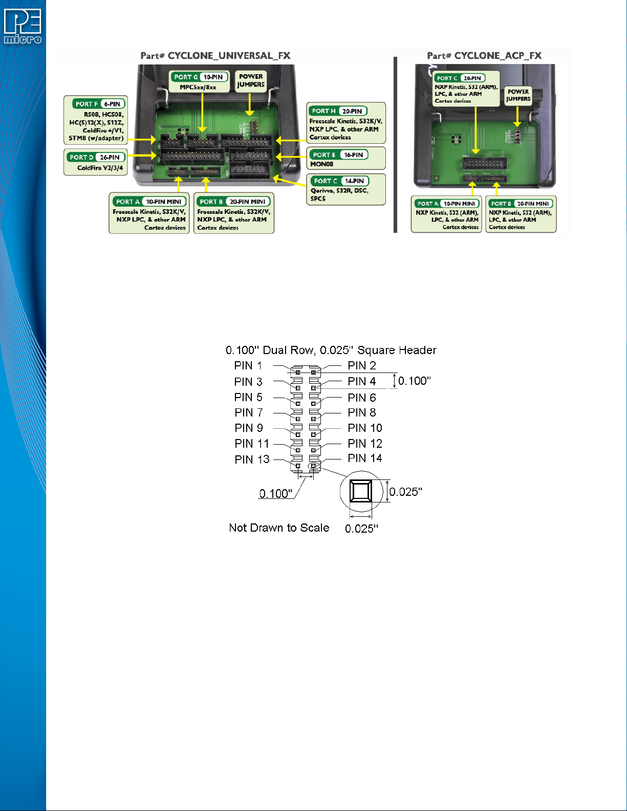
Figure 3-5: Target Headers & Power Jumpers (CYCLONE_UNIVERSAL_FX vs.CYCLONE_ACP_FX)
Mechanical drawings are shown below whose dimensions are representative of the pin size and
spacing of these headers.
Note: The number of pins depicted in the mechanical drawings may differ from the Cyclone headers; the
drawings are provided simply to demonstrate pin size and spacing.
Figure 3-6: 20-Pin Un-Keyed Header Dimensions
User Manual For CYCLONE FX Programmers 9
Page 15
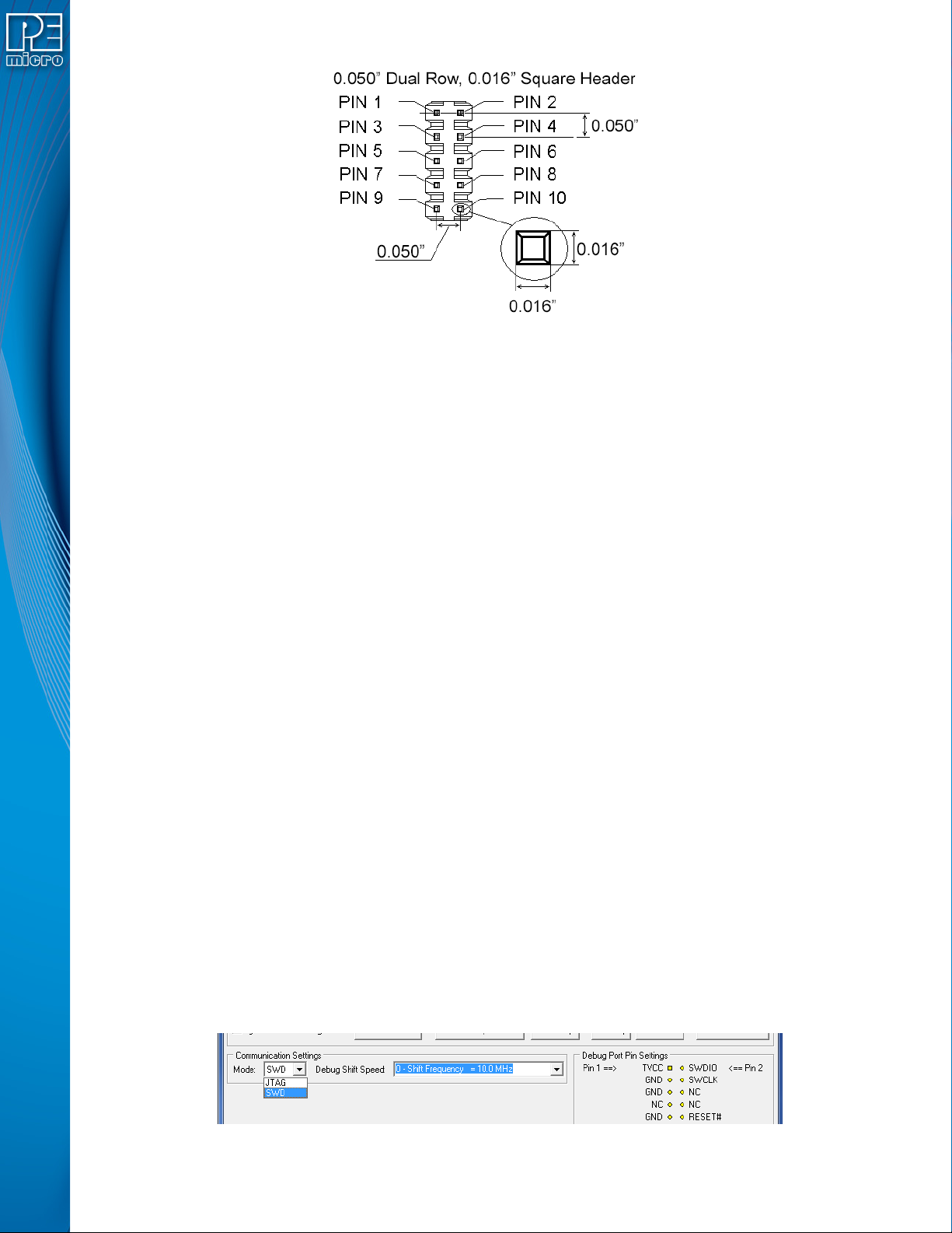
Figure 3-7: Mini 10-Pin and Mini 20-Pin Keyed Header Dimensions
3.18 Target Headers For Part# CYCLONE_ACP_FX
PEmicro Part# CYCLONE_ACP_FX features 3 ports labeled A-C.
3.18.1 PORT A: 10-Pin Keyed Mini Connector (Kinetis, S32 (ARM), other PEmicro-Supported ARM
devices)
3.18.1.1 JTAG Pin Assignments
The Cyclone provides a keyed 10-pin 0.050-inch pitch double row connector for ARM targets. The
location of the this header is indicated as PORT A in Figure 3-5. The 10-pin keyed mini connector
pin definitions for JTAG mode are as follows:
10-Pin Keyed Mini Connector JTAG Mode Pin Assignments
PIN 1 - TVCC TMS - PIN 2
PIN 3 - GND TCK - PIN 4
PIN 5 - GND TDO - PIN 6
PIN 7 - NC TDI - PIN 8
PIN 9 - NC* RESET - PIN 10
Note: *The pin is reserved for internal use within the PEmicro interface.
CYCLONE FX programmers also support SWD Mode. This replaces the JTAG connection with a
clock and single bi-directional data pin.
3.18.1.2 SWD Mode Pin Assignments
10-Pin Keyed Mini Connector SWD Mode Pin Assignments
PIN 1 - TVCC TMS/SWDIO - PIN 2
PIN 3 - GND TCK/SWCLK - PIN 4
PIN 5 - GND NC* - PIN 6
PIN 7 - NC NC* - PIN 8
PIN 9 - NC* RESET - PIN 10
Note: *The pin is reserved for internal use within the PEmicro interface.
SWD Mode is selected from the “Communication Mode” drop-down box in the Cyclone Image
Creation Utility:
Figure 3-8: Communications Mode Selection
User Manual For CYCLONE FX Programmers 10
Page 16
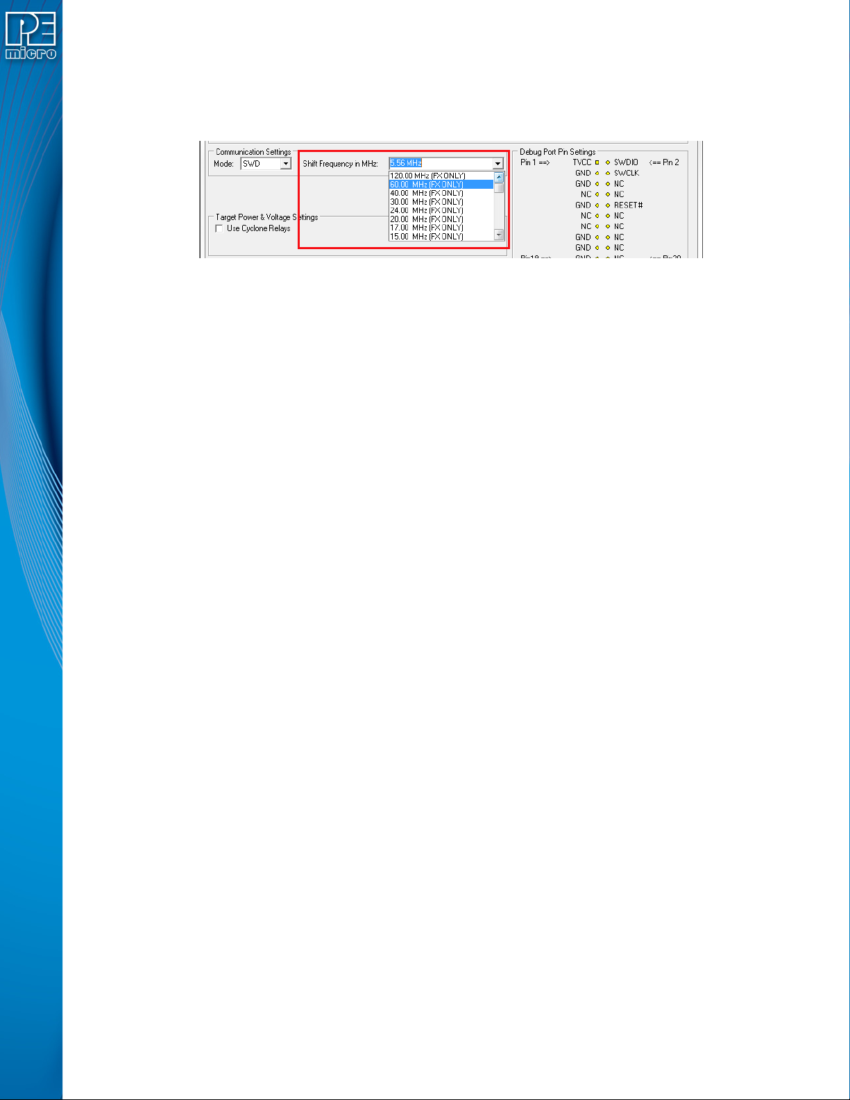
3.18.1.2.1 High-Performance Communications
If high-performance options are available for the selected device they will appear in the “Shift
Frequency in MHz” drop-down. CYCLONE FX programmers are capable of high-performance
communications when using certain ARM Cortex targets in SWD mode.
Figure 3-9: High-Performance Options
3.18.2 PORT B: 20-Pin Keyed Mini Connector (Kinetis, S32 (ARM), other PEmicro-Supported ARM
devices)
3.18.2.1 JTAG Mode Pin Assignments
The Cyclone provides a keyed 20-pin 0.050-inch pitch double row connector for ARM targets. The
location of the this header is indicated as PORT B in Figure 3-5. The 20-pin keyed mini connector
pin definitions for JTAG mode are as follows:
20-Pin Keyed Mini Connector JTAG Mode Pin Assignments
PIN 1 - TVCC TMS - PIN 2
PIN 3 - GND TCK - PIN 4
PIN 5 - GND TDO - PIN 6
PIN 7 - NC TDI - PIN 8
PIN 9 - NC* RESET - PIN 10
PIN 11 - NC NC* - PIN 12
PIN 13 - NC NC* - PIN 14
PIN 15 - GND NC* - PIN 16
PIN 17 - GND NC* - PIN 18
PIN 19 - GND NC* - PIN 20
Note: *The pin is reserved for internal use within the PEmicro interface.
3.18.2.2 SWD Mode Pin Assignments
CYCLONE FX programmers also support SWD Mode. This replaces the JTAG connection with a
clock and single bi-directional data pin.
20-Pin Keyed Mini Connector SWD Mode Pin Assignments
PIN 1 - TVCC TMS/SWDIO - PIN 2
PIN 3 - GND TCK/SWCLK - PIN 4
PIN 5 - GND NC* - PIN 6
PIN 7 - NC NC* - PIN 8
PIN 9 - NC* RESET - PIN 10
PIN 11 - NC NC* - PIN 12
PIN 13 - NC NC* - PIN 14
PIN 15 - GND NC* - PIN 16
PIN 17 - GND NC* - PIN 18
PIN 19 - GND NC* - PIN 20
Note: *The pin is reserved for internal use within the PEmicro interface.
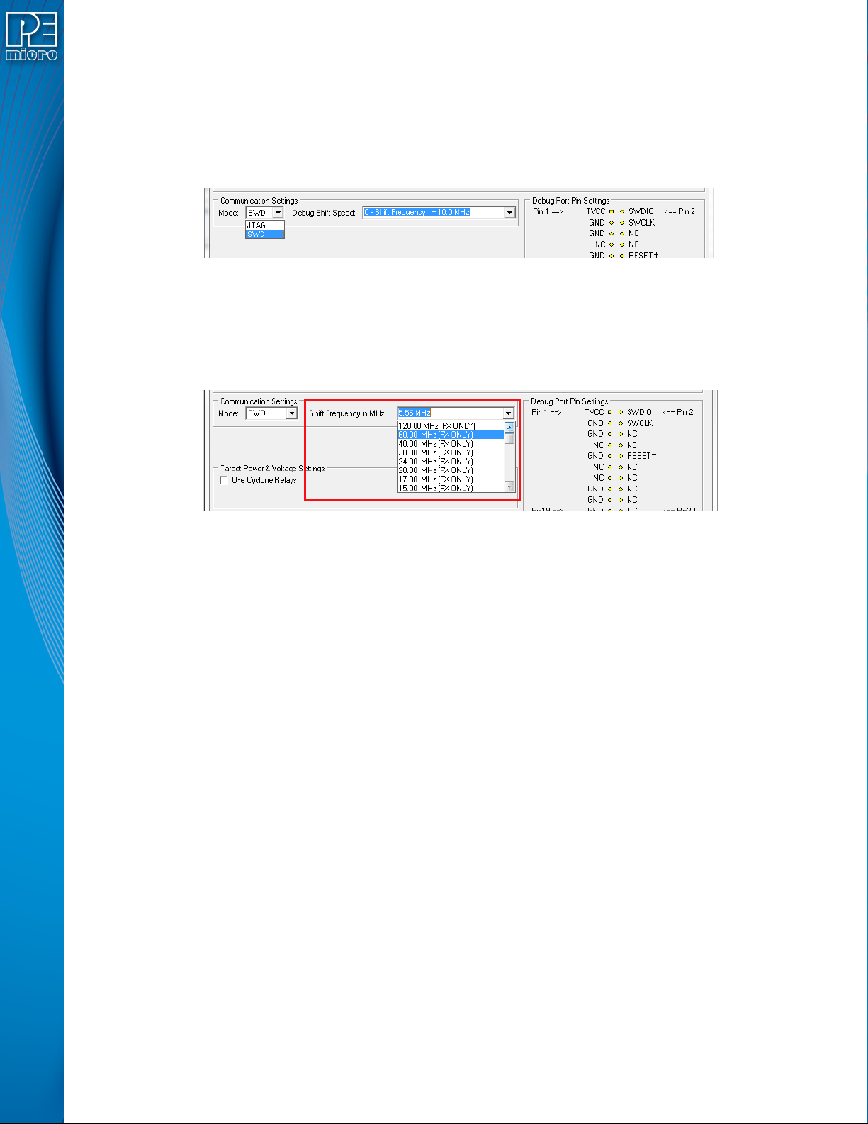
SWD Mode is selected from the “Communication Mode” drop-down box in the Cyclone Image
Creation Utility:
User Manual For CYCLONE FX Programmers 11
Page 17
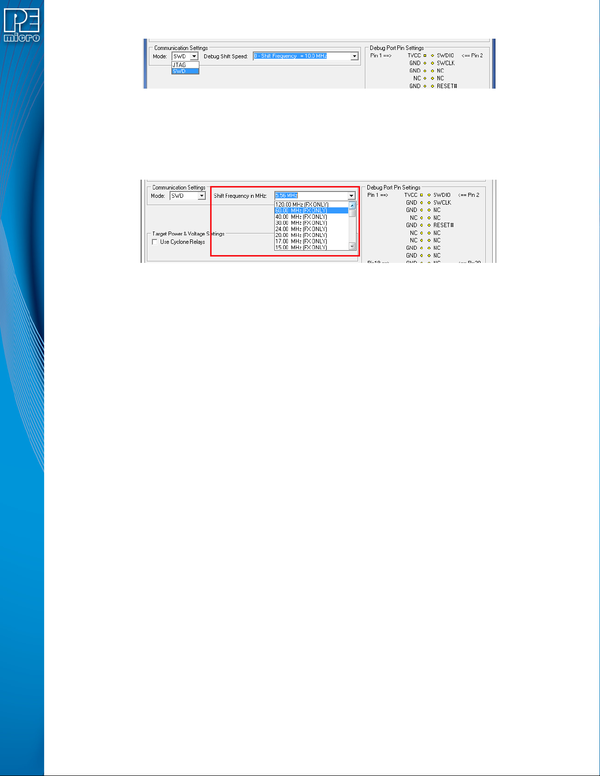
Figure 3-10: Communications Mode Selection
3.18.2.2.1 High-Performance Communications
If high-performance options are available for the selected device they will appear in the “Shift
Frequency in M Hz” drop-down. CYCLONE FX programmers are capable of high-performance
communications when using certain ARM Cortex targets in SWD mode.
Figure 3-11: High-Performance Options
3.18.3 PORT C: 20-Pin Debug Connector (Kinetis, S32 (ARM), other PEmicro-Supported ARM
devices)
3.18.3.1 JTAG Mode Pin Assignments
The Cyclone provides a 20-pin 0.100-inch pitch double row connector for ARM targets. The
location of the this header is indicated as PORT C under Part# CYCLONE_ACP_FX in Figure 3-5.
The 20-pin standard connector pin definitions for JTAG mode are as follows:
20-Pin Standard Connector JTAG Mode Pin Assignments
PIN 1 - TVCC NC* - PIN 2
PIN 3 - TRST or NC GND - PIN 4
PIN 5 - TDI GND - PIN 6
PIN 7 - TMS GND - PIN 8
PIN 9 - TCK GND - PIN 10
PIN 11 - NC* GND - PIN 12
PIN 13 - TDO GND - PIN 14
PIN 15 - RESET GND - PIN 16
PIN 17 - NC* GND - PIN 18
PIN 19 - NC* GND - PIN 20
Note: *The pin is reserved for internal use within the PEmicro interface.
3.18.3.2 SWD Mode Pin Assignments
CYCLONE FX programmers also support SWD Mode. This replaces the JTAG connection with a
clock and single bi-directional data pin.
20-Pin Standard Connector SWD Mode Pin Assignments
PIN 1 - TVCC NC* - PIN 2
PIN 3 - TRST or NC* GND - PIN 4
PIN 5 - NC* GND - PIN 6
PIN 7 - TMS/SWDIO GND - PIN 8
PIN 9 - TCK/SWCLK GND - PIN 10
PIN 11 - NC* GND - PIN 12
PIN 13 - NC* GND - PIN 14
PIN 15 - RESET GND - PIN 16
User Manual For CYCLONE FX Programmers 12
Page 18
PIN 17 - NC* GND - PIN 18
PIN 19 - NC* GND - PIN 20
Note: *The pin is reserved for internal use within the PEmicro interface.
SWD Mode is selected from the “Communication Mode” drop-down box in the Cyclone Image
Creation Utility:
Figure 3-12: Communications Mode Selection
3.18.3.2.1 High-Performance Communications
If high-performance options are available for the selected device they will appear in the “Shift
Frequency in MHz” drop-down. CYCLONE FX programmers are capable of high-performance
communications when using certain ARM Cortex targets in SWD mode.
Figure 3-13: High-Performance Options
3.19 Target Headers For Part# CYCLONE_UNIVERSAL_FX
PEmicro Part# CYCLONE_UNIVERSAL_FX features 6 ports labeled A-H.
3.19.1 PORT A: 10-Pin Keyed Mini Connector (Kinetis, S32 (ARM), other PEmicro-Supported ARM
devices)
3.19.1.1 JTAG Mode Pin Assignments
The Cyclone provides a keyed 10-pin 0.050-inch pitch double row connector for ARM targets. The
location of the this header is indicated as PORT A in Figure 3-5. The 10-pin keyed mini connector
pin definitions for JTAG mode are as follows:
10-Pin Keyed Mini Connector JTAG Mode Pin Assignments
PIN 1 - TVCC TMS - PIN 2
PIN 3 - GND TCK - PIN 4
PIN 5 - GND TDO - PIN 6
PIN 7 - NC TDI - PIN 8
PIN 9 - NC* RESET - PIN 10
*The pin is reserved for internal use within the PEmicro interface.
3.19.1.2 SWD Mode Pin Assignments
CYCLONE FX programmers also support SWD Mode. This replaces the JTAG connection with a
clock and single bi-directional data pin.
10-Pin Keyed Mini Connector SWD Mode Pin Assignments
PIN 1 - TVCC TMS/SWDIO - PIN 2
PIN 3 - GND TCK/SWCLK - PIN 4
User Manual For CYCLONE FX Programmers 13
Page 19
PIN 5 - GND NC* - PIN 6
PIN 7 - NC NC* - PIN 8
PIN 9* - NC RESET - PIN 10
*The pin is reserved for internal use within the PEmicro interface.
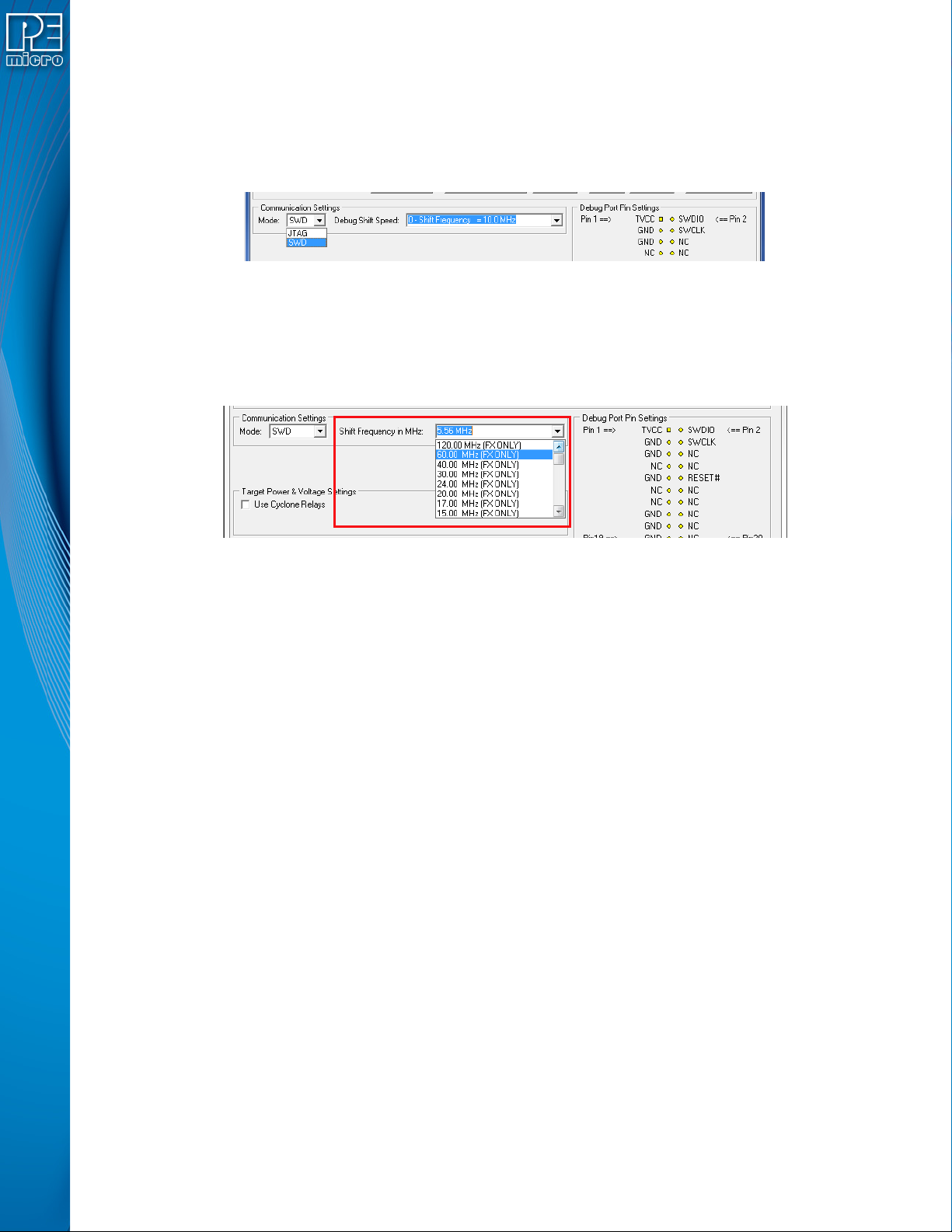
SWD Mode is selected from the “Communication Mode” drop-down box in the Cyclone Image
Creation Utility:
Figure 3-14: Communications Mode Selection
3.19.1.2.1 High-Performance Communications
If high-performance options are available for the selected device they will appear in the “Shift
Frequency in MHz” drop-down. CYCLONE FX programmers are capable of high-performance
communications when using certain ARM Cortex targets in SWD mode.
Figure 3-15: High-Performance Options
3.19.2 PORT B: 20-Pin Keyed Mini Connector (Kinetis, S32 (ARM), other PEmicro-Supported ARM
devices)
3.19.2.1 JTAG Mode Pin Assignments
The Cyclone provides a keyed 20-pin 0.050-inch pitch double row connector for ARM targets. The
location of the this header is indicated as PORT B in Figure 3-5. The 20-pin keyed mini connector
pin definitions for JTAG mode are as follows:
20-Pin Keyed Mini Connector JTAG Mode Pin Assignments
PIN 1 - TVCC TMS - PIN 2
PIN 3 - GND TCK - PIN 4
PIN 5 - GND TDO - PIN 6
PIN 7 - NC TDI - PIN 8
PIN 9 - NC* RESET - PIN 10
PIN 11 - NC NC* - PIN 12
PIN 13 - NC NC* - PIN 14
PIN 15 - GND NC* - PIN 16
PIN 17 - GND NC* - PIN 18
PIN 19 - GND NC* - PIN 20
3.19.2.2 SWD Mode Pin Assignments
CYCLONE FX programmers also support SWD Mode. This replaces the JTAG connection with a
User Manual For CYCLONE FX Programmers 14
Page 20
clock and single bi-directional data pin.
20-Pin Keyed Mini Connector SWD Mode Pin Assignments
PIN 1 - TVCC TMS/SWDIO - PIN 2
PIN 3 - GND TCK/SWCLK - PIN 4
PIN 5 - GND NC* - PIN 6
PIN 7 - NC NC* - PIN 8
PIN 9 - NC* RESET - PIN 10
PIN 11 - NC NC* - PIN 12
PIN 13 - NC NC* - PIN 14
PIN 15 - GND NC* - PIN 16
PIN 17 - GND NC* - PIN 18
PIN 19 - GND NC* - PIN 20
*The pin is reserved for internal use within the PEmicro interface.
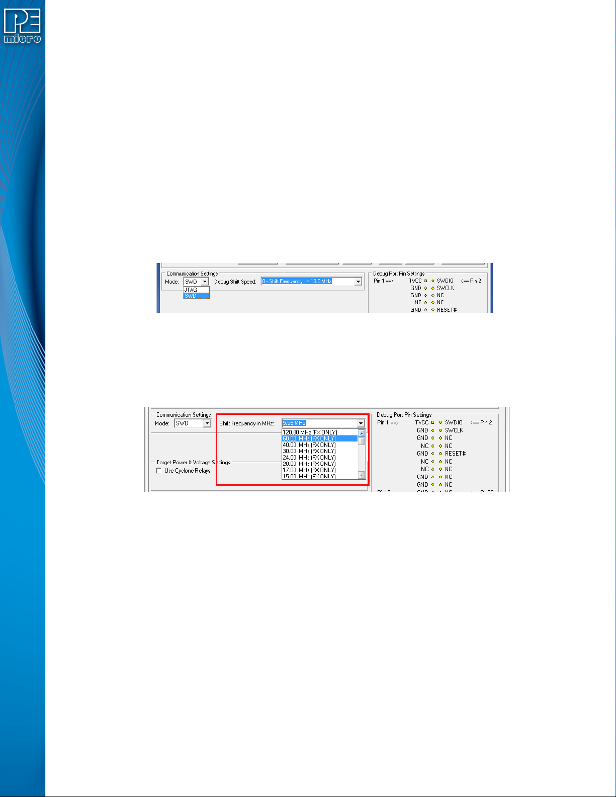
SWD Mode is selected from the “Communication Mode” drop-down box in the Cyclone Image
Creation Utility:
Figure 3-16: Communications Mode Selection
3.19.2.2.1 High-Performance Communications
If high-performance options are available for the selected device they will appear in the “Shift
Frequency in MHz” drop-down. CYCLONE FX programmers are capable of high-performance
communications when using certain ARM Cortex targets in SWD mode.
Figure 3-17: High-Performance Options
3.19.3 PORT C: 14-Pin Debug Connector (MPC55xx-57xx, SPC5, DSC, S32 (Power))
The Cyclone provides a standard 14-pin 0.100-inch pitch dual row 0.025-inch square header for
MPC55xx-57xx, DSC (MC56F8xxx), S32R, or STMicroelectronics’ SPC5 targets. The location of
the this header is indicated as PORT C in Figure 3-5.
MPC55xx-57xx, SPC5, or S32 (Power) Pinout
TDI 12GND
TDO 34GND
TCK 56GND
NC 78NC
RESET 910TMS
VDDE7 11 12 GND
RDY 13 14 JCOMP
User Manual For CYCLONE FX Programmers 15
Page 21
DSC Pinout
TDI 12GND
TDO 34GND
TCK 56GND
NC 78NC/KEY
RESET 910TMS
VDD 11 12 GND
NC* 13 14 TRST
*The pin is reserved for internal use within the PEmicro interface.
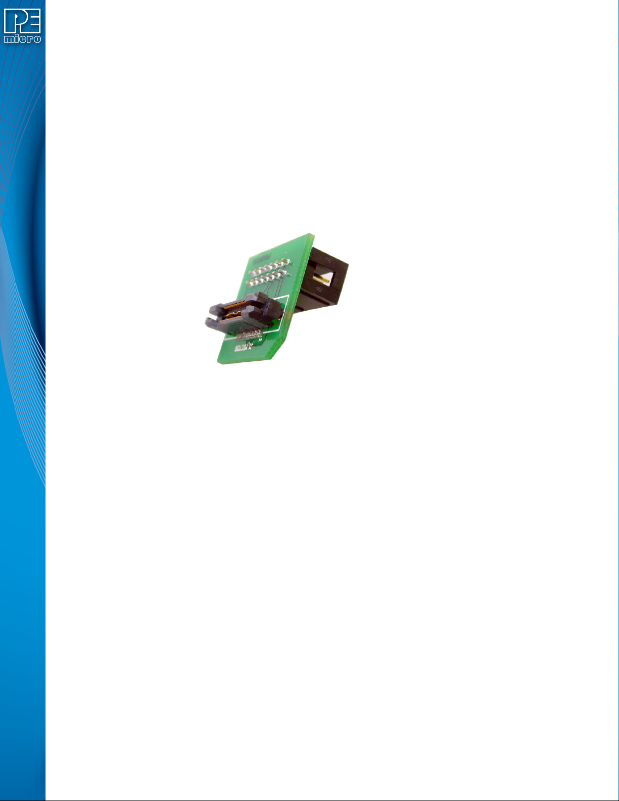
3.19.3.1 BERG14-to-MICTOR38 Optional Connector
PEmicro offers a 14-pin BERG to 38-pin MICTOR adapter, sold separately, that may be used on
Port C of the CYCLONE FX. The PEmicro part number is BERG14-TO-MICTOR38.
Figure 3-18: BERG14-TO-MICTOR38 Adapter (Sold Separately)
3.19.4 PORT D: 26-Pin Debug Connector (ColdFire V2/3/4)
The Cyclone provides a standard 26-pin 0.100-inch pitch dual row 0.025-inch square header for
ColdFire MCF52xx/53xx/54xx family of microprocessors. This port connects to the target hardware
using either the ColdFire extension cable for synchronous ColdFire targets such as MCF5272 &
MCF5206E (PEmicro part# CABLE-CF-ADAPTER, sold separately), or a standard 26-pin ribbon
cable for asynchronous ColdFire targets (included). Please refer to each processor’s user manual
to identify whether it is a synchronous or asynchronous interface. The location of the this header is
indicated as PORT D in Figure 3-5.
ColdFire V2/3/4 Pinout
N/C 12BKPT
GND 34DSCLK
GND 56NC*
RESET 78DSI
VCC 910DSO
GND 11 12 PST3
PST2 13 14 PST1
PST0 15 16 DDATA3
DDATA2 17 18 DDATA1
DDATA0 19 20 GND
N/C 21 22 N/C
GND 23 24 CLK
VCC 25 26 TEA
*The pin is reserved for internal use within the PEmicro interface.
User Manual For CYCLONE FX Programmers 16
Page 22
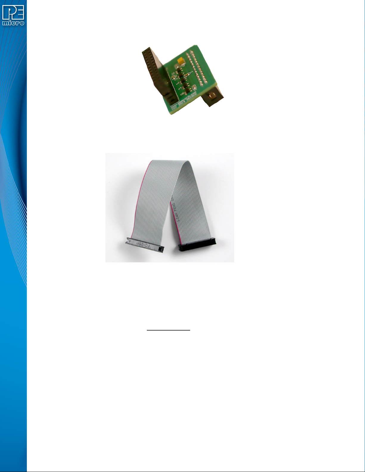
The ColdFire adapter for Synchronous targets and ribbon cable for Asynchronous targets is
pictured below:
Figure 3-19: ColdFire Adapter (part# CABLE_CF_ADAPTER (Rev. B), for synchronous ColdFire
targets, sold separately)
Figure 3-20: ColdFire Ribbon Cable (for asynchronous ColdFire targets, included with Cyclone)
3.19.5 PORT E: 16-Pin Debug Connector (MON08)
The Cyclone provides a 16-pin 0.100-inch pitch double row connector for MON08 targets. The
location of the this header is indicated as PORT E in Figure 3-5. The MON08 header adopts the
standard pin-out from MON08 debugging with some modifications. The general pin-out is as
follows:
MON08 Signals
PIN 1 - NC* GND - PIN 2
PIN 3 - NC** RST - PIN 4
PIN 5 - NC* IRQ - PIN 6
PIN 7 - NC* MON4 - PIN 8
PIN 9 - NC* MON5 - PIN10
PIN11 - NC* MON6 - PIN12
PIN13 - OSC MON7 - PIN14
PIN15 - Vout MON8 - PIN16
*The pin is reserved for internal use within the PEmicro interface.
**The pin is reserved for internal use within the PEmicro interface only when using an MR8 target.
3.19.6 PORT F: 6-Pin Debug Connector (RS08, HCS08, HC(S)12(X), S12Z, ColdFire +/V1, STM8 w/
User Manual For CYCLONE FX Programmers 17
Page 23
adapter)
The Cyclone provides a standard 6-pin 0.100-inch pitch dual row 0.025-inch square header for
ColdFire V1, S12Z, 68(S)12(X), 68HCS08, RS08, and STMicroelectronics’ STM8 targets. The
location of the this header is indicated as PORT F in Figure 3-5. The header uses the NXP
standard pin configuration, listed here for reference:
ColdFire V1, 68(S)12(X), 68HCS08, and RS08 Signals
PIN 1 - BKGD GND - PIN 2
PIN 3 - NC RESET - PIN 4
PIN 5 - NC TVCC - PIN 6
S12Z Signals
Note:* indicates optional signal
PIN 1 - BKGD GND - PIN 2
PIN 3 - PDO* RESET - PIN 4
PIN 5 - PDOCLK* TVCC - PIN 6
6-Pin STM8 Signals
PIN 1 -SWIM** GND - PIN 2
PIN 3 - NC* RESET - PIN 4
PIN 5 - NC* TVCC - PIN 6
*The pin is reserved for internal use within the PEmicro interface.
** All the signals are direct connect except the SWIM line which requires a 680 Ohm pull-up
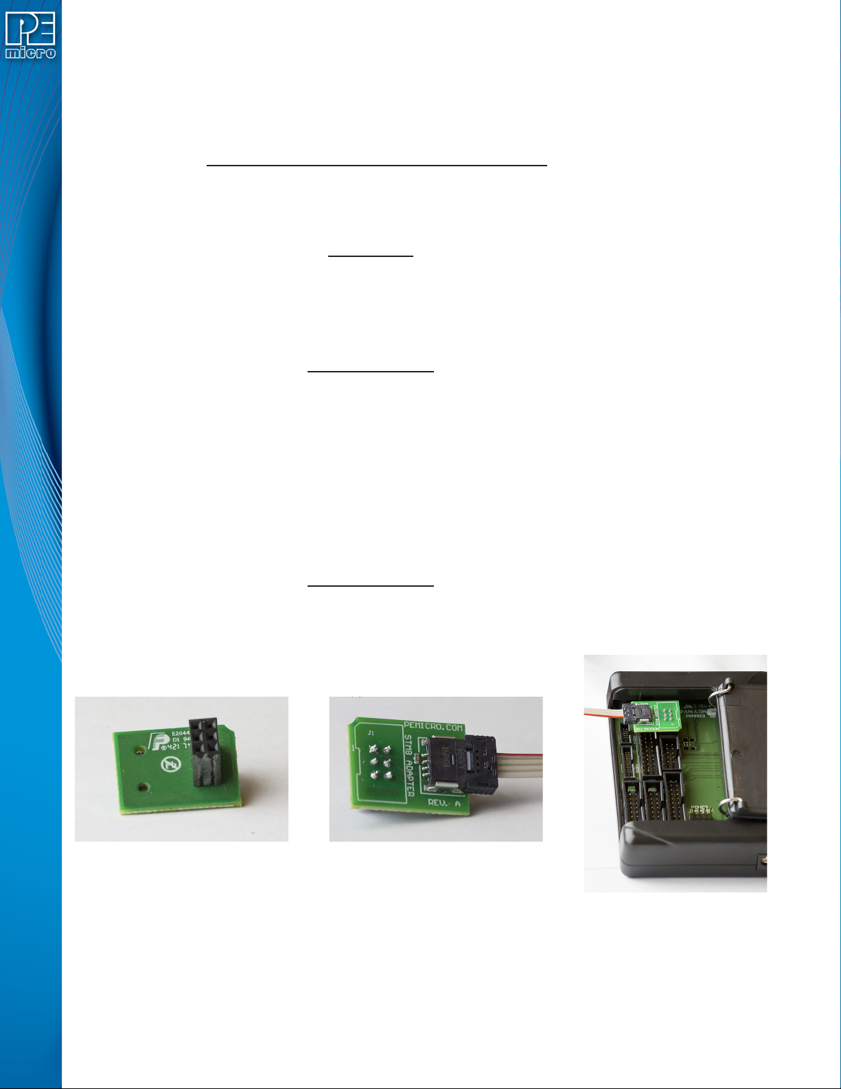
PEmicro also offers a separate STM8 adapter (part# CU-CUFX-STM8-ADPT) that can be plugged
into the 6-pin header of the Cyclone (see Figure 3-21). The adapter offers 4 pins signals from an
ERNI connector.
4-Pin STM8 Signals
(Requires STM8 Adapter, sold separately)
PIN 1 - TVCC SWIM - PIN 2
PIN 3 - GND RESET - PIN 4
Figure 3-21: STM8 Adapter: 1) Bottom, 2) Top, 3) Connected To 6-Pin Header of
Cyclone_Universal_FX (Adapter Sold Separately)
3.19.7 PORT G: 10-Pin Debug Connector (Power MPC5xx/8xx)
The Cyclone provides a standard 10-pin 0.100-inch pitch dual row 0.025-inch square header for
Power MPC5xx/8xx BDM targets. The location of the this header is indicated as PORT G in Figure
User Manual For CYCLONE FX Programmers 18
Page 24

3-5.
Power MPC5xx/8xx BDM Pinout
NC* 12SRESET#
GND 34DSCLK
GND 56NC*
HRESET# 78DSDI
VDD 910DSDO
*The pin is reserved for internal use within the PEmicro interface.
3.19.8 PORT H: 20-Pin Debug Connector (Kinetis, S32 (ARM), other PEmicro-Supported ARM
devices)
3.19.8.1 JTAG Mode Pin Assignments
The Cyclone provides a 20-pin 0.100-inch pitch double row connector for ARM targets. The
location of the this header is indicated as PORT H under Part# CYCLONE_UNIVERSAL_FX in
Figure 3-5. The 20-pin standard connector pin definitions for JTAG mode are as follows:
20-Pin Standard Connector JTAG Mode Pin Assignments
PIN 1 - TVCC NC - PIN 2*
PIN 3 - TRST or NC* GND - PIN 4
PIN 5 - TDI GND - PIN 6
PIN 7 - TMS GND - PIN 8
PIN 9 - TCK GND - PIN 10
PIN 11 - NC* GND - PIN 12
PIN 13 - TDO GND - PIN 14
PIN 15 - RESET GND - PIN 16
PIN 17 - NC* GND - PIN 18
PIN 19 - NC* GND - PIN 20
*The pin is reserved for internal use within the PEmicro interface.
3.19.8.2 SWD Mode Pin Assignments
CYCLONE FX programmers also support SWD Mode. This replaces the JTAG connection with a
clock and single bi-directional data pin.
20-Pin Standard Connector SWD Mode Pin Assignments
PIN 1 - TVCC NC* - PIN 2
PIN 3 - TRST or NC* GND - PIN 4
PIN 5 - NC* GND - PIN 6
PIN 7 - TMS/SWDIO GND - PIN 8
PIN 9 - TCK/SWCLK GND - PIN 10
PIN 11 - NC* GND - PIN 12
PIN 13 - NC* GND - PIN 14
PIN 15 - RESET GND - PIN 16
PIN 17 - NC* GND - PIN 18
PIN 19 - NC* GND - PIN 20
*The pin is reserved for internal use within the PEmicro interface.
SWD Mode is selected from the “Communication Mode” drop-down box in the Cyclone Image
Creation Utility:
User Manual For CYCLONE FX Programmers 19
Page 25
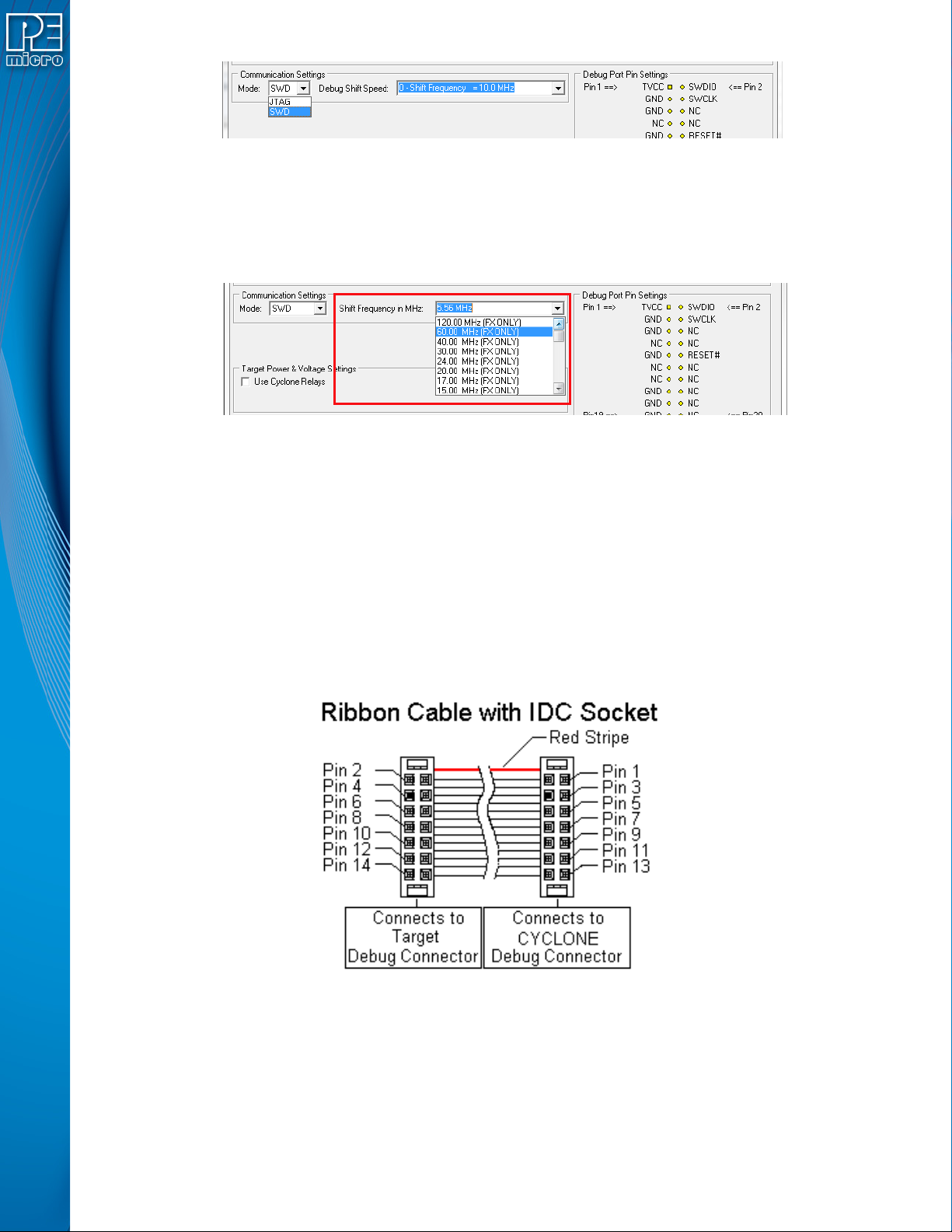
3.19.8.2.1 High-Performance Communications
If high-performance options are available for the selected device they will appear in the “Shift
Frequency in MHz” drop-down. CYCLONE FX programmers are capable of high-performance
communications when using certain ARM Cortex targets in SWD mode.
3.20 Ribbon Cable
CYCLONE FX programmers communicate with the target through ribbon cables. The ribbon
cables for standard debug connectors have a 0.100-inch centerline dual row socket IDC assembly
(not keyed). The ribbon cables for 10- and 20-pin mini debug connectors have a 0.050-inch
centerline dual row socket IDC assembly (keyed). The ribbon cables are designed such that the
Cyclone’s Debug Connector has the same pinout as the Target Header, i.e., Pin 1 of the Cyclone’s
Debug Connector is connected to Pin 1 of the Target Header. As an example, Figure 3-24
sketches the connection mechanism (looking down into the sockets) for a 14-pin ribbon cable.
Ribbon cables for other supported architectures use a similar scheme, but may have more or
fewer pins.
Figure 3-22: Communications Mode Selection
Figure 3-23: High-Performance Options
Figure 3-24: Ribbon Cable Example Diagram, When Looking Into IDC Socket
User Manual For CYCLONE FX Programmers 20
Page 26
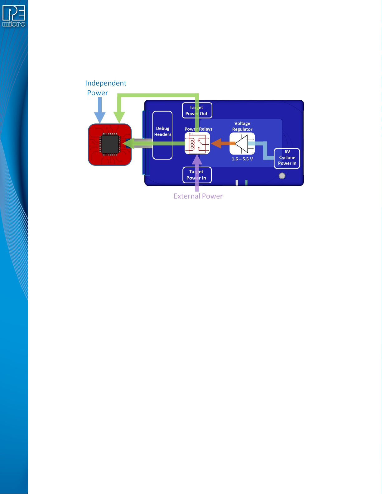
4 TARGET POWER MANAGEMENT
Different target devices may require different power schemes which depend on the design of the
target board, target voltages, and even the device architecture. PEmicro has designed the
CYCLONE FX to be capable of powering a target before, during, and after programming. Power
can be sourced at many voltage levels from the Cyclone itself, or sourced by an external power
supply and switched by the Cyclone.
Figure 4-1: Five different paths to power a target
The versatility of the Cyclone power scheme gives the user the utmost flexibility, and includes the
following features:
• Provides power through a power jack or through the debug connector
• Provides internally generated voltage from 1.6v-5.5v at up to 500mA
• Switches an external power supply voltage, up to 24V at 1amp
• Selectively powers the target before, during, and after programming
• Powers down the target connections between programming operations
• Uses power switching to aid entry into debug mode for certain targets
• Provides target voltage and current measurement capabilities
If target power is required, each target board may vary where the power is sourced from, externally
or internally, and how it is channeled to the target: through the debug header or to a separate
connector to the board. Power that is passed through and managed by the Cyclone goes through
power relays so it can be power cycled. This is extremely useful because it also allows the power
to be off during setup and automatically powered on by the Cyclone for programming. For some
devices, the process of entering debug mode requires that the device be powered down and
powered back up. Power can also be left in a desired power state, either on or off.
4.1 Cyclone Configuration
There are two different places Power Management is configured and they should be matched:
first, by the jumpers on the CYCLONE FX, and second, in the setup of the programming image.
The Cyclone jumpers are the most important because they are the physical connection to the
target. The Cyclone has an easy access panel that reveals debug header connections for a variety
of different architectures, and a 2x4 jumper block for configuring power management of the target.
The specific location of the jumpers is indicated by the label POWER JUMPERS in Figure 4-3.
This set of 4 jumpers can be used to set 5 different power management schemes for the target.
User Manual For CYCLONE FX Programmers 21
Page 27
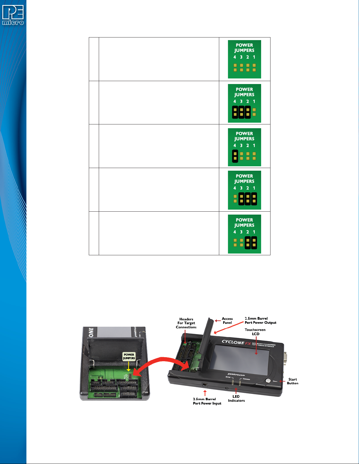
Note: If these jumpers are not set correctly, the Cyclone will not function as intended.
1 Target is powered independently
Power provided externally (center +) and
2
managed by Cyclone, power out to debug
ribbon cable.
Power provided externally (center +) and
3
managed by Cyclone, power out to 2.5 mm
output jack (center +)
Power provided by Cyclone, power out to
4
debug ribbon cable
Power provided by Cyclone, power out to
5
2.5 mm output jack (center +)
Figure 4-2: Cyclone Power Schemes & Corresponding Jumper Settings
The bottom edge of the CYCLONE FX has a Power In jack for externally provided power, and the
top edge of the Cyclone has Power Out jack, for when power schemes including these are used
(see Figure 4-3). One of the provided ribbon cables is connected to the appropriate debug header
based on the specific target architecture.
Figure 4-3: Cyclone Hardware Features: Power Jumpers and Target Headers
The power settings that are set by the jumpers are a physical connection and take precedence.
User Manual For CYCLONE FX Programmers 22
Page 28
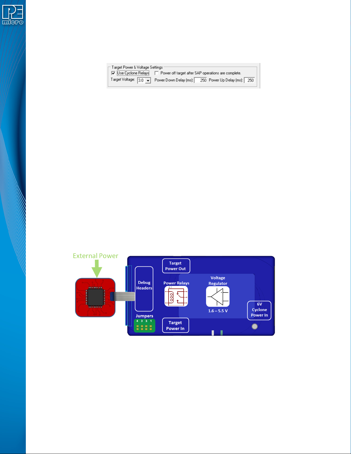
After the basic hardware setup, target power and voltage settings are also set in the creation of a
SAP (stand-alone programming) image. At a minimum the SAP image contains all the commands
to Erase, Program, and Verify a programming image. More sophisticated power selections in the
SAP image can control the relays, target voltage, delays, and power down after SAP operations,
as shown in the selection dialog.
Target voltages (with appropriate jumper settings) in the range of 1.6 to 5.5 volts may be provided.
There is also the option to select the internal Cyclone relays to power cycle the Cyclone during
programming, and set the length of delays during power up and down. This is extremely useful to
make sure the power is off when hooking up the target. Power cycling is especially important for
architectures that require it to enter debug mode. The SAP image settings may even be used to
turn off the target power once programming is completed, to ensure that the microcontroller is left
in a halted state and not running.
4.2 Cyclone Setup
Below is a tutorial that demonstrates how to set up the CYCLONE FX in each of the 5 power
configurations. A very common configuration is the independently powered target. In this power
scenario, the Cyclone will detect and use the power on the target for the appropriate debug
communication voltages.
Figure 4-4: Target Power & Voltage Settings
4.2.1 Independently Powered Target
In the simplest and most common scenario, no jumpers are set, so the target is powered
independently from the Cyclone. No power is passed through the debug header, just the standard
debug signals. The Cyclone automatically detects the target power and sets the debug signals to
match.
Figure 4-5: Independently Powered Target
4.2.2 Power provided by the Cyclone to the debug cable
It is also possible for the Cyclone to generate power through an internal regulator in the range of
1.6 to 5.5 Volts. In the jumper configuration below, the Cyclone generates the power through a
voltage regulator, and passes it through the power relays and out through the debug ribbon cable,
which is set up during the SAP image creation. There is only one connection to the target
processor which will handle both the communication and the power. In this scenario, external
power must not be connected to the Power In jack since it is already being provided.
User Manual For CYCLONE FX Programmers 23
Page 29
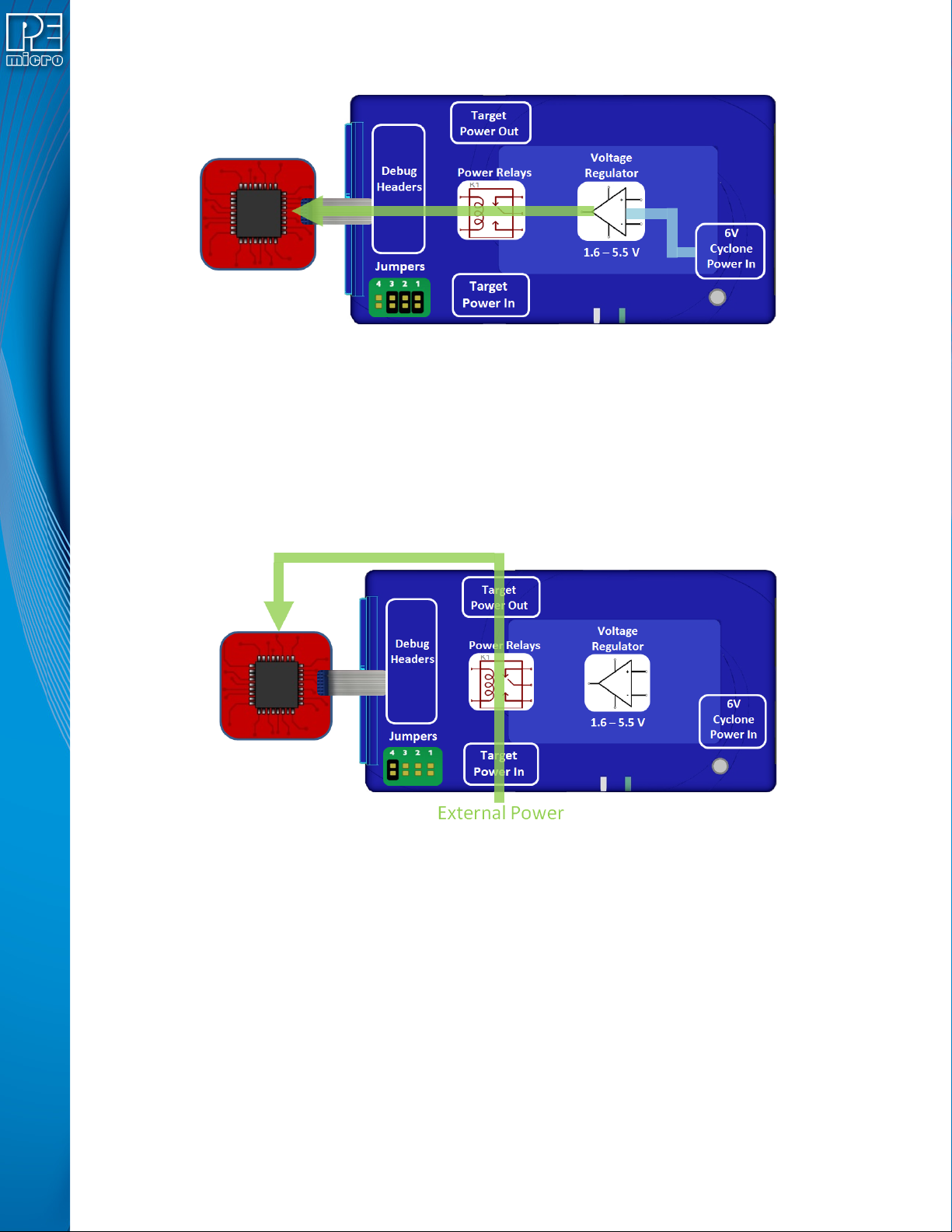
Figure 4-6: Power Provided by the Cyclone to the Debug Cable
4.2.3 External Power passed through the Cyclone and out 2.5 mm barrel port
It is also possible to provide external power, passed through the Cyclone power relays, and back
out to be available to power the target board externally. This is useful when the user wants to
control the power to the target and the target board has an external power connector. Setting a
single jumper will connect the barrel port input connector on the bottom edge of the Cyclone,
through the relays, to a matched 2.5 mm barrel port output connector on the top edge of the
Cyclone, so that the power can be routed into and back out of the Cyclone.
Figure 4-7: External Power Passed Through the Cyclone and Out 2.5 mm Barrel Port
4.2.4 External Power passed through the Cyclone to the debug cable
In a slightly different scenario, the user may wish to provide power to the target through the debug
cable. On the bottom edge of the Cyclone is a 2.5 mm Power In port barrel which will pass power
through target relays which lets the Cyclone take control of the power cycling during programming.
This simple setup requires only an input to the Cyclone and a single ribbon cable connection to the
target board that handles both communication and power. The external power provided must be
between 1.6 to 5.5 volts.
User Manual For CYCLONE FX Programmers 24
Page 30
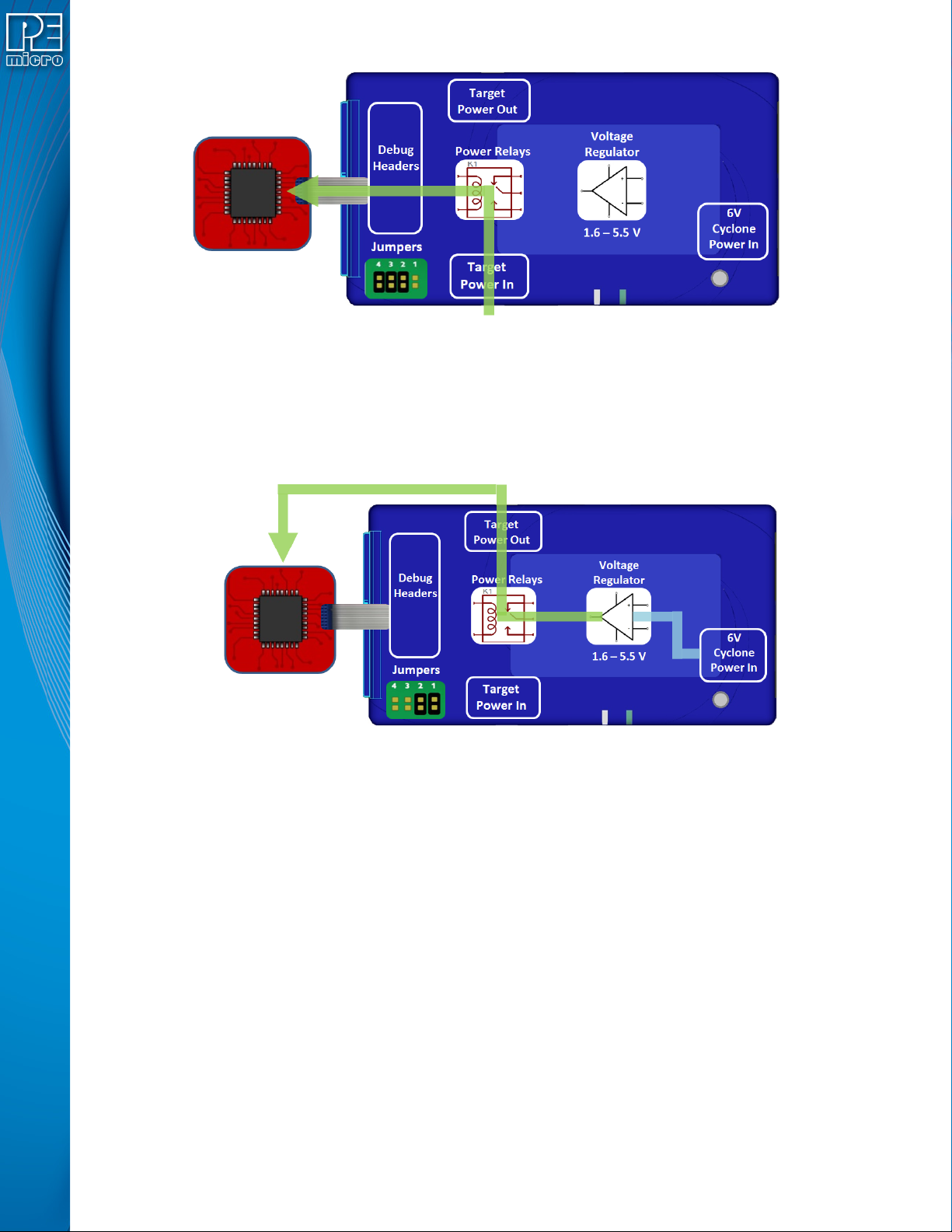
Figure 4-8: External Power Passed Through the Cyclone to the Debug Cable
4.2.5 Power provided by the Cyclone and out 2.5 mm barrel port
In a slightly different scenario, the user may wish to have the Cyclone provide power, but power
the target via an external connector on the target. The voltage supplied to the target is determined
by the settings in the SAP image. When generating the SAP image the Cyclone relays must be
selected as well as the correct voltage level for the target.
Figure 4-9: Power Provided by the Cyclone and Out 2.5 mm Barrel Port
4.3 Setup Reminders
The most important step when providing power out to a target is to check the Cyclone's jumper
settings to make sure they match the intended power setup. The jumpers control the power
settings which determine how power is supplied, regardless of the SAP image settings. If the
jumpers are set for power to be provided through the Cyclone, and the target is externally
powered, this is a conflict and may cause damage to the board.
In the case where power is being supplied through the Cyclone and the target is not being
powered on, the user should first check the jumper settings to make sure they match the
intended power setup. Second, the user should check to make sure the SAP image has the ‘Use
Cyclone Relays’ box checked with the appropriate voltage level selected.
User Manual For CYCLONE FX Programmers 25
Page 31
5 TOUCHSCREEN LCD MENU
This chapter describes the Cyclone’s touchscreen LCD menu. Figure 5-1 shows an overview of
the menu structure.
Note: This menu will change as features are added to the CYCLONE FX, so if your menu does not
match what is displayed here, please check PEmicro’s website, www.pemicro.com, for a user
manual containing the latest LCD Menu operations information.
5.1 Home Screen
The home screen appears when the CYCLONE FX is powered on, or when the Home
button is tapped.
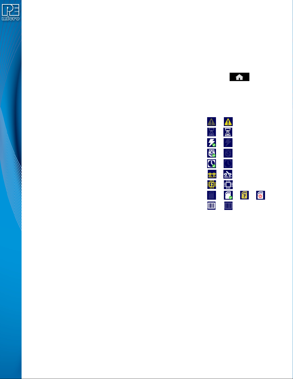
5.1.1 Icons
A row of icons in the upper right corner indicates the status of various attributes of the Cyclone.
Note: The user may tap on the row of icons to view the meaning of each of the currently displayed icons.
Real-Time clock Enabled & Working: Yes / No
SDHC Memory Card: None / Valid / Unformattted / Reset Cyclone**
Barcode Scanner: Detected / Not Detected
* Target Device Is Powered - “Yes” indicates that the CYCLONE FX detects power on the Vcc pin
of the target device programming header.
** SDHC Memory Card - “Reset Cyclone” indicates that the Cyclone needs to be reset before the
SDHC card will register as Valid. The user can push the Reset button which is located on the front
side of the Cyclone, below the LED indicators.
5.1.2 Configurable Display Area
The main area of the home screen can be configured to optionally display the following
information, by using the Cyclone IP Configuration Utility (see Section 5.2.3.5.4 - Configure
Home Screen):
1. Firmware version of the Cyclone (always shown).
2. IP address assigned to the Cyclone.
3. Name assigned to the Cyclone.
Cyclone Unit Status: Ok / Bad
Programming Status: Ready / Busy
Target Power Relays: On / Off
USB-To-PC Enumerated: Yes / No
Cyclone Power Relays: Closed / Open
Target Device Is Powered*: Yes / No
4. Number of programming images in the Cyclone’s memory.
5. Name of the selected programming image.
6. First serial number associated with the selected image
7. Current status.
8. Results of the last operation performed.
9. Time and date.
User Manual For CYCLONE FX Programmers 26
Page 32
10. Status Window and Main Menu button (always shown).
11. Target voltage and/or current
12. Programming count & limit
5.1.3 Status Window
The status window appears in the lower left corner of the home screen and displays the results of
programming operations.
5.1.4 Error Information Icon
When the Cyclone experiences an error during programming operations, the Info icon will appear
to the left of the Menu button (or AUX button, if configured).
Info Icon:
Press the Info icon to view a detailed description of the error.
5.1.5 AUX Button (Appears If Configured)
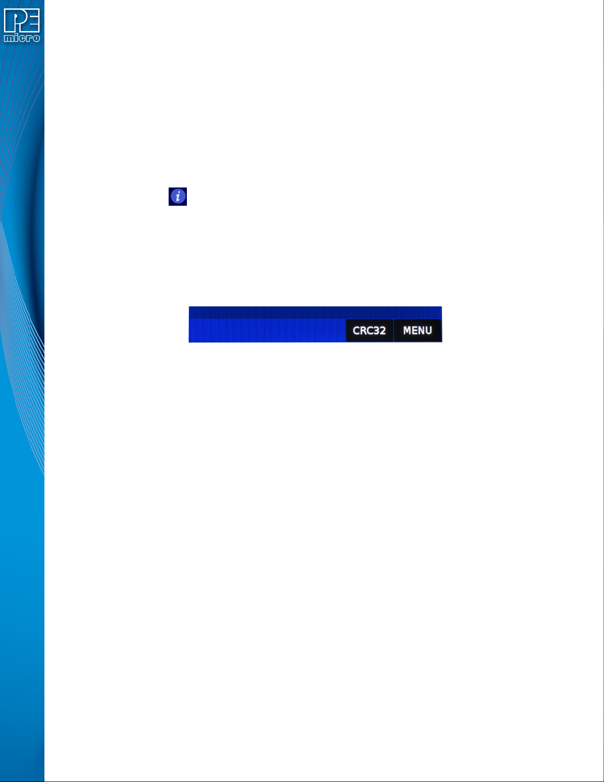
The Cyclone allows the user to add an Auxiliary (AUX) button to the home screen which will
perform a specific function when pressed. The specific function is chosen by the user when the
AUX button is configured. The AUX button will appear on the home screen to the left of the “Menu”
button, in the lower right corner of the home screen.
Figure 5-1: AUX Button On Home Screen (configured to perform CRC32 function)
For information on how to configure the AUX button, see Section 5.2.4 - Status.
5.2 Main Menu
The Main Menu is accessible by pressing the “Menu” button when the Home Screen is displayed.
The Main Menu contains the following selections:
User Manual For CYCLONE FX Programmers 27
Page 33
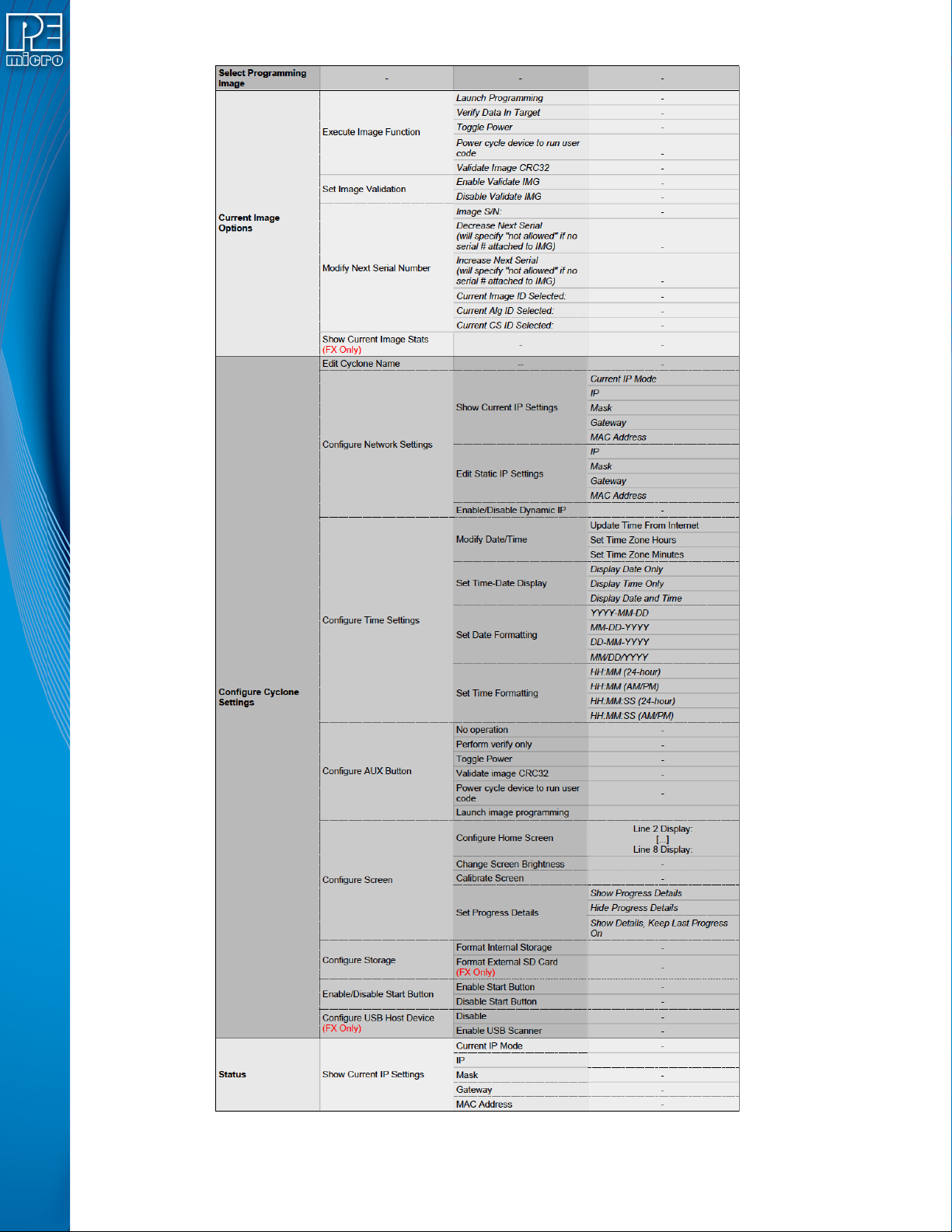
Figure 5-2: Main Menu Structure
User Manual For CYCLONE FX Programmers 28
Page 34

5.2.1 Select Programming Image
Displays a list of the available programming images so that the user may select one for
programming. Images in the Cyclone’s internal memory are preceded by the designation “IN” and
numbered sequentially, i.e., IN1: first image name, IN2: second image name. If the SDHC port of
the Cyclone contains a memory card, any programming images that reside on the SD card will be
preceded by the designation “EX” in similar fashion.
You may tap the appropriate image to select it. The image name shown is the one specified in the
Cyclone Configuration Utility when saving the image to the Cyclone/SD card.
5.2.2 Current Image Options
This menu presents options that allow the user to select or configure programming images on the
CYCLONE FX.
5.2.2.1 Execute Image Function
Execute Specific SAP Function presents four Stand-Alone Programming functions that you may
execute by tapping the function that you wish to execute:
5.2.2.1.1 Launch Programming
This allows the user to execute the programming function. The CYCLONE FX will program the
target device, if able, using the currently selected programming image. This is functionally
equivalent to pressing the Start button.
5.2.2.1.2 Verify Data In Target
Performs a verify function on the data that has been programmed into the target device.
5.2.2.1.3 Toggle Power
Toggles the target power and makes sure all ports are driven to debug mode level.
5.2.2.1.4 Power Cycle Device To Run User Code
Toggles the target power and maintains tri-state mode for all signals.
5.2.2.1.5 Validate Image CRC32
Allows the user to perform a CRC32 validation on the currently selected programming image.
5.2.2.1.6 Launch Image Programming
Launches the selected programming image. Replaces the hardware Start Button.
5.2.2.2 Set Image Validation
Allows the user to choose between two validation settings: 1) validate the image each time the
Start button is pressed, or 2) do not validate the image.
5.2.2.3 Modify Next Serial Number
Presents options that display the current serial number and allow the user to increase or decrease
the next serial number. Tap “Current Image ID Selected” to view/choose the desired programming
image; tap “Current Alg ID Selected” to view/choose the desired programming algorithm; use
“Current CS ID Selected” to view/choose the desired Choose Serial file. The adjustment buttons
will display “Increase Not Allowed” and “Decrease Not Allowed” if the image/algorithm/CS files that
the user has selected to do not allow for this operation.
5.2.2.4 Show Current Image Stats (FX Only)
Displays current statistics, if any, for Image Programmed Count & Maximum Allowed, Errors
Logged & Maximum Allowed, and Date Range Allowed. These limits can be set in the Image
Creation Utility when using the CYCLONE FX.
User Manual For CYCLONE FX Programmers 29
Page 35

Note: When Current Image Stats is displayed as a home screen item, only Image Programmed
Count & Maximum Allowed are displayed on the home screen.
5.2.3 Configure Cyclone Settings
Presents options that allow the user to choose to configure the CYCLONE FX network settings,
time/date settings, and LCD touchscreen display settings, or to set the display to dynamic.
5.2.3.1 Edit Cyclone Name
Allows the user to edit the name of the Cyclone using the on-screen keyboard. Click “Done” to
save the new Cyclone name or “Cancel” to exit without saving a new Cyclone name. This name
will be displayed on the CYCLONE FX home screen if the Cyclone is configured to do so.
5.2.3.2 Configure Network Settings
Presents options that allows the user to view or edit various IP settings, toggle the IP settings
between static and dynamic, and re-name the CYCLONE FX.
5.2.3.2.1 Show Current IP Settings
This menu allows you to view the CYCLONE FX IP address, Mask, and Gateway, and MAC
address. You may also tap these entries to edit, as long as the Cyclone is set to Static IP mode.
Dynamic vs. Static
There are two schemes for assigning IP addresses. One is the Static IP addressing mode. This
involves the user manually setting the IP address for every device on the network. In this case, it
falls to the user to ensure the IPs assigned do not conflict and are within the boundaries of the
network. The other is the Dynamic Host Configuration Protocol (DHCP). This involves setting up a
separate server to manage the IP addresses. The server is given a list of valid IP addresses for the
network. Using a predetermined set of rules, each new device that wishes to connect to the
network is given an IP address by the server. This takes the task of managing the validity and
uniqueness of IP addresses out of the user's hands and relegates it to the server. CYCLONE FX
programmers are capable of using either Static IP addressing or DHCP.
5.2.3.2.2 Edit Static IP Settings
This menu allows you to edit the Cyclone’s IP address, Mask, and Gateway, and view the
Cyclone’s MAC address. If you are unable to edit these values, you may wish to check to be
certain that the Cyclone is not set to Dynamic IP mode.
IP
Edit IP Numbers allows the user to set an IP number for the Cyclone. The current IP number is
displayed on the second line. Tap a number to edit and use the touchscreen keyboard to set the
new number. When you are finished, hit Done. If you change your mind and decide not to save, hit
Cancel to leave the IP number as is and return to the Main Menu.
Mask
Edit IP Mask allows the user to set an IP Mask for the Cyclone. The current IP Mask is displayed
on the second line. Use the Up/Down buttons to scroll through the characters. To select a
character, hit the Select button. When you are finished, scroll through the characters until you
reach the -> (right-arrow) character. Selecting this character will complete the process. The default
IP mask is 255.255.255.0.
Gateway
Edit IP Gateway allows the user to set the IP Gateway for the Cyclone. The current IP Gateway is
displayed on the second line. Use the Up/Down buttons to scroll through the characters. To select
a character, hit the Select button. When you are finished, scroll through the characters until you
reach the -> (right-arrow) character. Selecting this character will complete the process.
MAC Address
Show MAC Address displays the current MAC address for the Cyclone.
User Manual For CYCLONE FX Programmers 30
Page 36

5.2.3.2.3 Enable/Disable Dynamic IP
Allows the user to toggle the Cyclone configuration between utilizing a Static IP address or a
Dynamic IP address. The user must reset the CYCLONE FX after changing from Static to
Dynamic or vice-versa. The reset button on the front side of the unit may be used.
5.2.3.3 Configure Time Settings (Cyclone Time / Real Time Clock)
The CYCLONE FX is equipped with a Real Time Clock (RTC) module designed to keep accurate
timing even when the Cyclone is turned off. The Date & Time are displayed on the home screen.
This menu presents options that allow the user to configure the Cyclone’s various date/time/
timezone settings, including formatting options.
5.2.3.3.1 Modify Date / Time
1. Update Time from Internet - Connects to an SNTP server, fetches the current time, and
saves it to the Cyclone. When executed it displays a
message that this can freeze the Cyclone for up to 3
minutes – This is due to an invalid ARP response due to a
bad gateway configuration. Proper configuration will
ensure the problem is resolved. If the network connection
is not configured/connected this displays a message that
the time failed to update. If it is successful no message is
displayed.
2. Set Time Zone Hours - Allows you to set the timezone offset, in hours +/-, from GMT
time
3. Set Time Zone Minutes - Allows you to set the timezone offset, in minutes +/-, from
GMT time
5.2.3.3.2 Set Time-Date Display
Allows you set the Cyclone’s Time-Date Display to one of the following configurations:
1. Display Date Only
2. Display Time Only
3. Display Date and Time
5.2.3.3.3 Set Date Formatting
Allows you to select how the date is displayed. The options are:
1. YYYY-MM-DD
2. MM-DD-YYYY
3. DD-MM-YYYY
4. MM/DD/YYYY
5.2.3.3.4 Set Time Formatting
Allows you to select how the time is displayed. The options are:
1. HH:MM (24-hour)
2. HH:MM (AM/PM)
3. HH:MM:SS (24-hour)
4. HH:MM:SS (AM/PM)
5.2.3.4 Configure AUX Button
Allows the user to configure an auxiliary (AUX) button which (if configured) will be labeled
appropriately and displayed to the left of the Menu button on the Cyclone’s touchscreen LCD.
When pressed, the AUX button will perform the task for which it has been configured. The options
User Manual For CYCLONE FX Programmers 31
Page 37

that may be assigned to the AUX button are:
1. No Operation - No operation is assigned to the AUX button and it will not be displayed on
the LCD screen.
2. Perform Verify Only - Verifies the data on the target device against the data in the programming image.
3. Toggle Power - Toggles the Cyclones power relays off/on.
4. Validate Image CRC32 - Validates the CRC32 of the data on the target device against that
of the data in the programming image.
5. Power Cycle Device To Run User Code - Toggles the target power and maintains tri-state
mode for all signals.
6. Launch Image Programming - Launches the selected programming image. Replaces the
hardware Start Button.
5.2.3.5 Configure Screen
This menu presents options that allow the user to adjust or customize the Cyclone’s LCD
touchscreen display in various ways.
5.2.3.5.1 Change Screen Brightness
Allows the user to adjust the brightness of the LCD touchscreen. The “Increase” and “Decrease”
buttons will raise or lower the brightness level, respectively, in increments of 10%. Brightness can
be adjusted from between 100% - 10%. Press “Done” to exit.
5.2.3.5.2 Calibrate Screen
Allows the user to click on specified points on the LCD touchscreen in order to calibrate the
accuracy of the touch function. Follow the on-screen instructions.
5.2.3.5.3 Set Progress Details
This configures the display to present more detailed information during the progress of
programming, including the specific programming steps that are performed and specific
information about the programming and verifying procedure. The user may select “Show Details,
Keep Last Progress On,” “Show Progress Details,” or “Hide Progress Details.”
5.2.3.5.4 Configure Home Screen
This menu allows you to choose what information to display on Lines 2-8 of the home screen.
Available elements to display consist if information such as: the current IP address, the Cyclone
name, the number of images, etc. In this way the user can customize the display to provide the
information that they find most useful. There is a separate button for each of Lines 2-8. Tapping on
the button for a specific Line brings up a list of elements that you can choose to display on that
Line of the home screen. If the list of elements is greater than one page, tap the More button to
view the rest of the available elements. Tap the element that you want to display on that line and
then tap Done to save your selection.
Note: The CYCLONE FX allows one additional option for display: the target device’s voltage and/
or current.
5.2.3.6 Configure Storage
This menu selection allows the user to format the Cyclone’s internal memory. This menu will also
allow the user to format an SD card located in the Cyclone’s memory expansion slot. Select
“Format Internal Storage” or “Format External SD Card”. The user will be prompted to ensure that
they wish to format the corresponding memory. Tap “Yes” to format, or “Cancel” to go back to the
previous menu option without formatting the memory.
User Manual For CYCLONE FX Programmers 32
Page 38

5.2.3.7 Enable/Disable Start Button
This menu option gives the user the option to disable the physical Start Button. Programming can
then be initiated via the Cyclone Control Suite, or by a digital start button on the Cyclone screen if
you have the AUX button set to the "Launch Image Programming" option.
The physical Start Button can always be re-enabled via this same menu toggle.
5.2.3.8 Configure USB Host Device (FX Only)
This menu selection allows the user to either Enable or Disable a barcode scanner connected to
the Cyclone FX’s USB Extension Port.
Select Enable to provide power to and turn on a connected barcode scanner. The Enable setting
is persistent. Once Enabled, the scanner will be powered and turned on whenever the Cyclone is
powered. To disable the barcode scanner select Disable.
5.2.4 Status
This menu contains a selection that allow the user to view status information regarding various
aspects of the Cyclone. This menu will likely be expanded with future updates.
5.2.4.1 Show Current IP Settings
Allows the user to view the Cyclone’s Current IP Mode, IP Address, Mask, Gateway, and MAC
Address.
User Manual For CYCLONE FX Programmers 33
Page 39
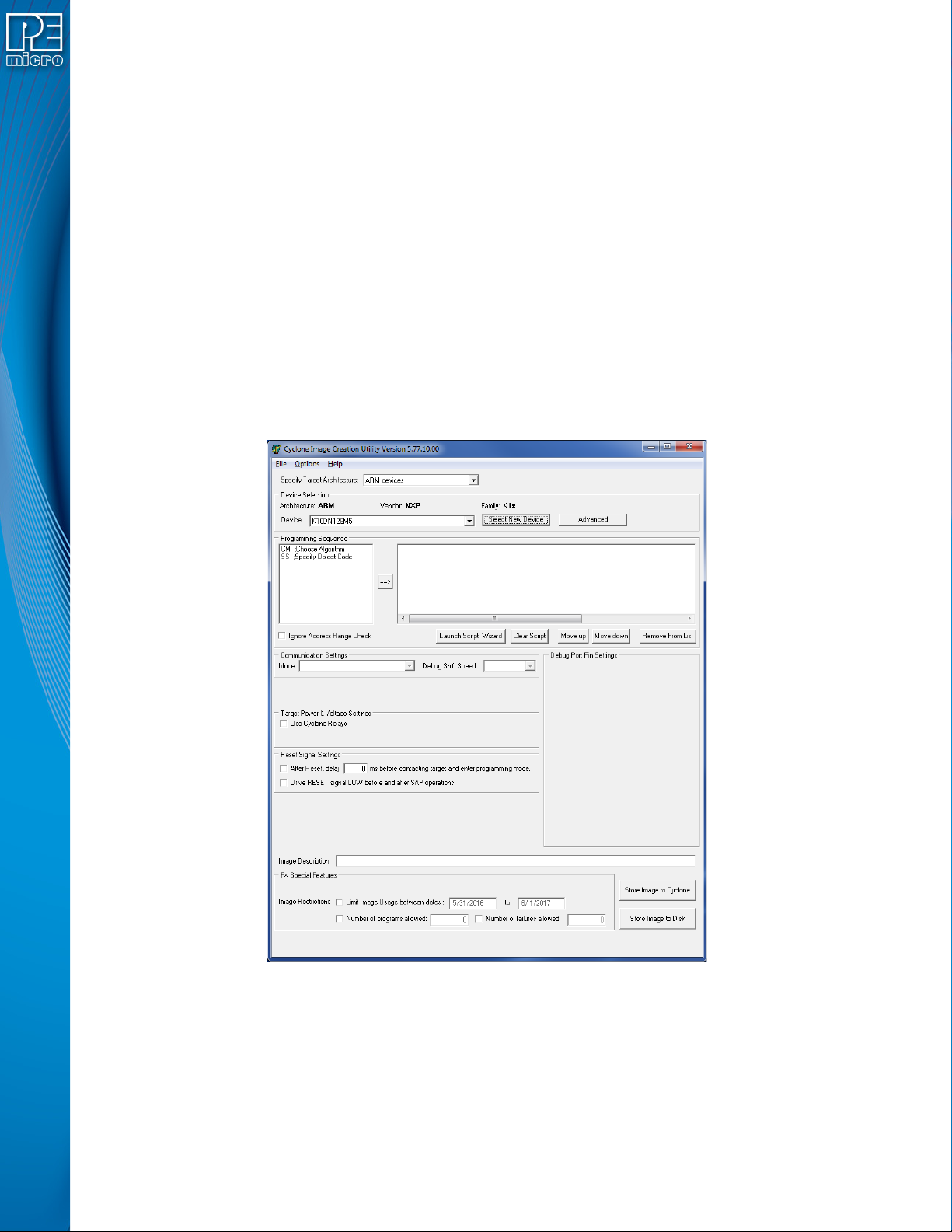
6 CREATING PROGRAMMING IMAGES
The Cyclone Image Creation Utility is used to create programming images which may be loaded
into the Cyclone. The user creates programming images based on data sets to be programmed
and programming instructions which are all self contained. The next step is to download these
programming images to the Cyclone via the GUI, Console, or SDK. Programming can then be
launched either manually via the button, or automatically via the Console.exe or SDK. Learn about
how to download and launch programming images in CHAPTER 8 - CYCLONE PROGRAMMER
AUTOMATED CONTROL (CYCLONE CONTROL SUITE).
Note: If the user wishes to use a programming image created with an earlier generation Cyclone (such
as the Cyclone PRO or MAX, or the Cyclone for ARM devices Rev. A/B) they should first convert
the image using the conversion utility described in CHAPTER 13 - TROUBLESHOOTING.
6.1 Create A Stand-Alone Programming (SAP) Image
This chapter describes in detail how to configure the CYCLONE FX for stand-alone programming
using the Cyclone Image Creation Utility, shown in Figure 6-1. The CYCLONE FX does not
require a target to be connected when it is being configured. However, the power of the CYCLONE
FX must be turned on and one of the communications interfaces must be connected to the
CYCLONE FX if an image is to be stored on it.
Figure 6-1: Cyclone Image Creation Utility
6.1.1 Specify Target Architecture
CYCLONE FX programmers support ARM Cortex devices from several manufacturers** -
including NXP’s Kinetis and LPC devices. If you are using PEmicro Part#
CYCLONE_UNIVERSAL_FX, this Cyclone also supports these 8-16/32-bit architectures: NXP’s
S32, ColdFire® V2/V3/V4, ColdFire+/V1, MPC5xx/8xx, Qorivva® (MPC5xxx), DSC, ARM® Nexus
(MAC7xxx), S12Z, HC(S)12(X), HCS08, HC08, and RS08 devices, as well as STMicroelectronics
SPC5 & STM8 (w/ adapter) devices.
User Manual For CYCLONE FX Programmers 34
Page 40
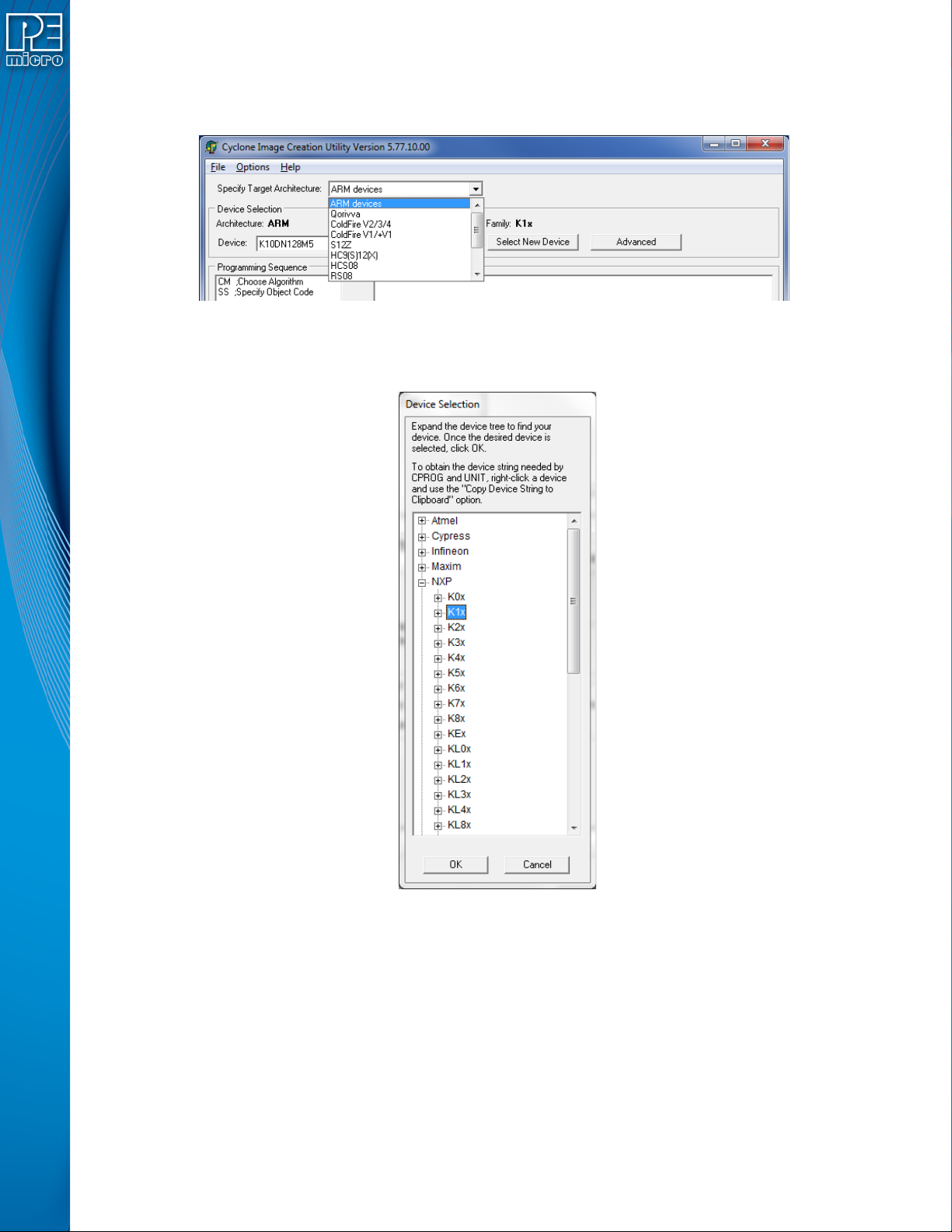
**For a complete index of PEmicro-supported ARM Cortex devices, please view pemicro.com/
arm.
The user may select the CPU Manufacturer from the drop-down list:
Figure 6-2: CPU Manufacturer Selection
The user may select the appropriate target architecture by clicking on "Select New Device." A
Device Selection window will appear.
Figure 6-3: Device Selection
6.1.1.1 Security Settings - MPC55xx-57xx Only
If you selected MPC55xx-57xx, the Cyclone Image Creation Utility will display an area called
Security Settings (see Figure 6-4). If your Qorivva device supports uncensoring, click the “Device
supports uncensoring” checkbox and select the appropriate bit depth for the device’s password
(64-bit or 256-bit). The box to the right is where the password must be entered. Optionally you may
use the Browse button to navigate to a text file that contains the correct password for the device.
The contents of the text file that you select will automatically be used to fill the password text box.
User Manual For CYCLONE FX Programmers 35
Page 41
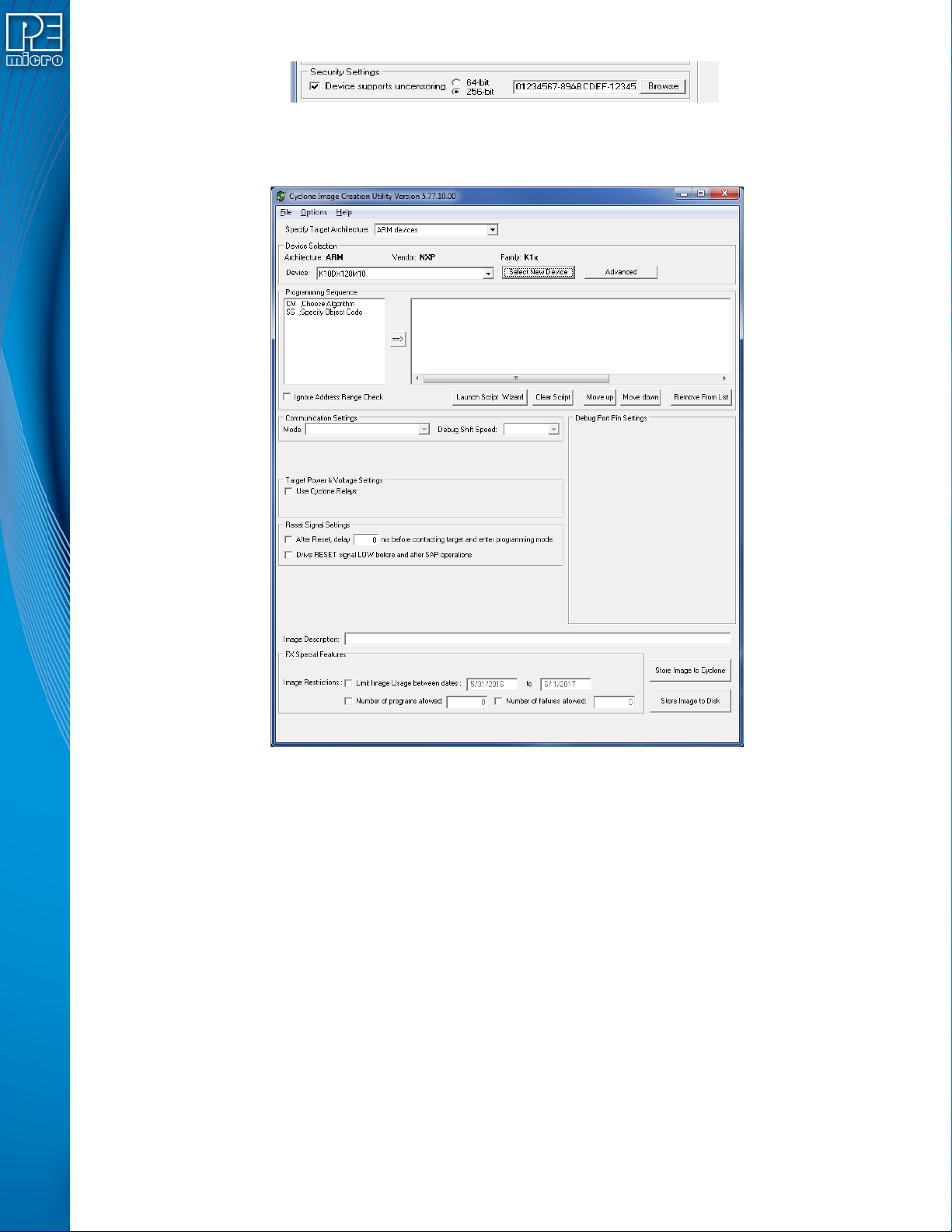
Figure 6-4: Security Settings - MPC55xx-57xx Only
6.1.2 Specify Programming Script
Figure 6-5: Specify Programming Script
This is a two-panel interface. The left panel provides a list of available programming functions. The
right panel displays the ordering of the functions.
To specify the programming algorithm for the target, double-click on the Choose Algorithm (CM)
function in the left panel. Or, you may highlight it and add it to the right panel using the arrow (->).
This opens the Load Programming Algorithm dialog.
User Manual For CYCLONE FX Programmers 36
Page 42
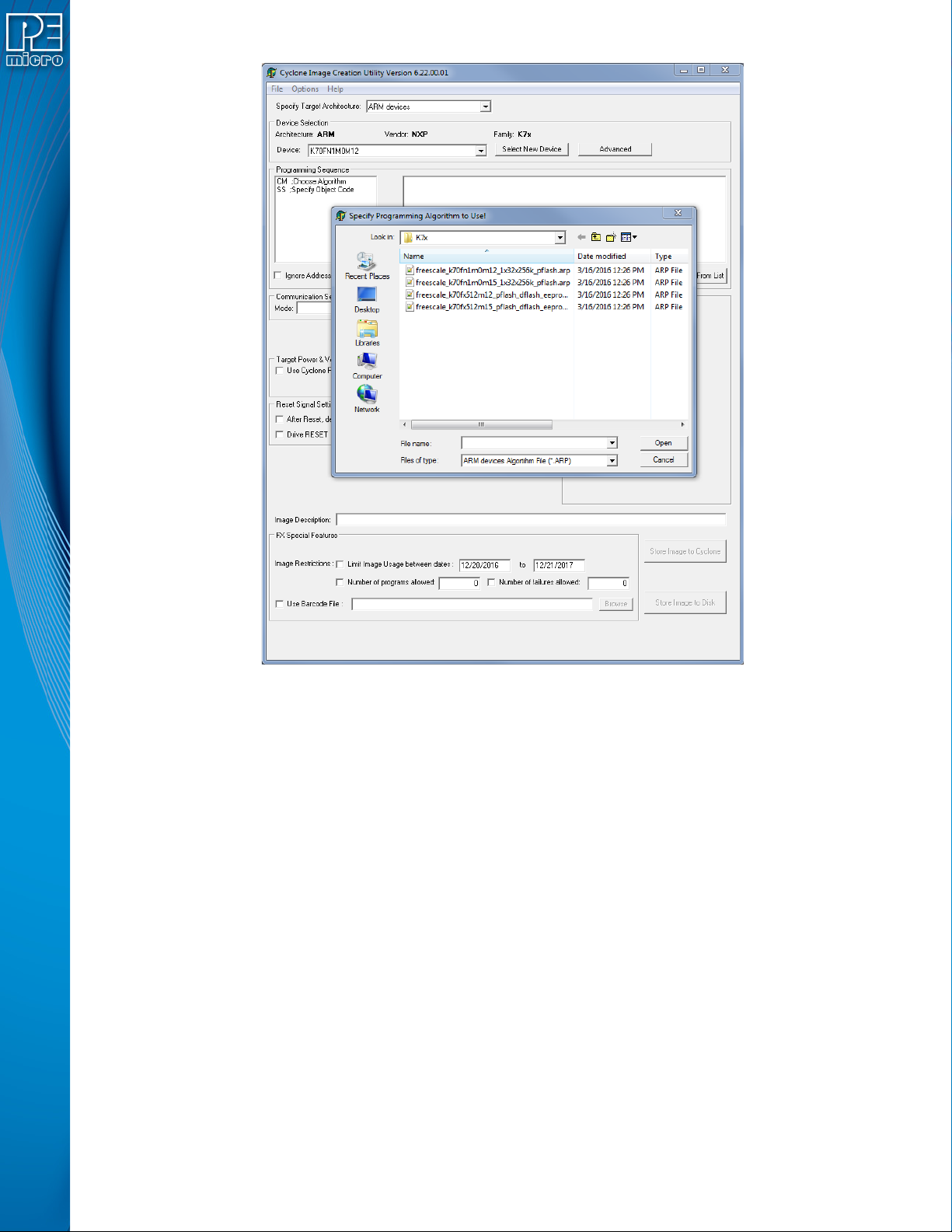
Figure 6-6: Load Programming Algorithm Dialog
Select the programming algorithm that you wish to use.
Similarly, to specify the S-Record to be programmed into the target, double-click on Specify SRecord (SS) in the left panel. This opens a dialog which allows you to select the appropriate SRecord.
Once both the algorithm and S-Record are selected, the full list of programming functions
becomes available in the left panel.
User Manual For CYCLONE FX Programmers 37
Page 43
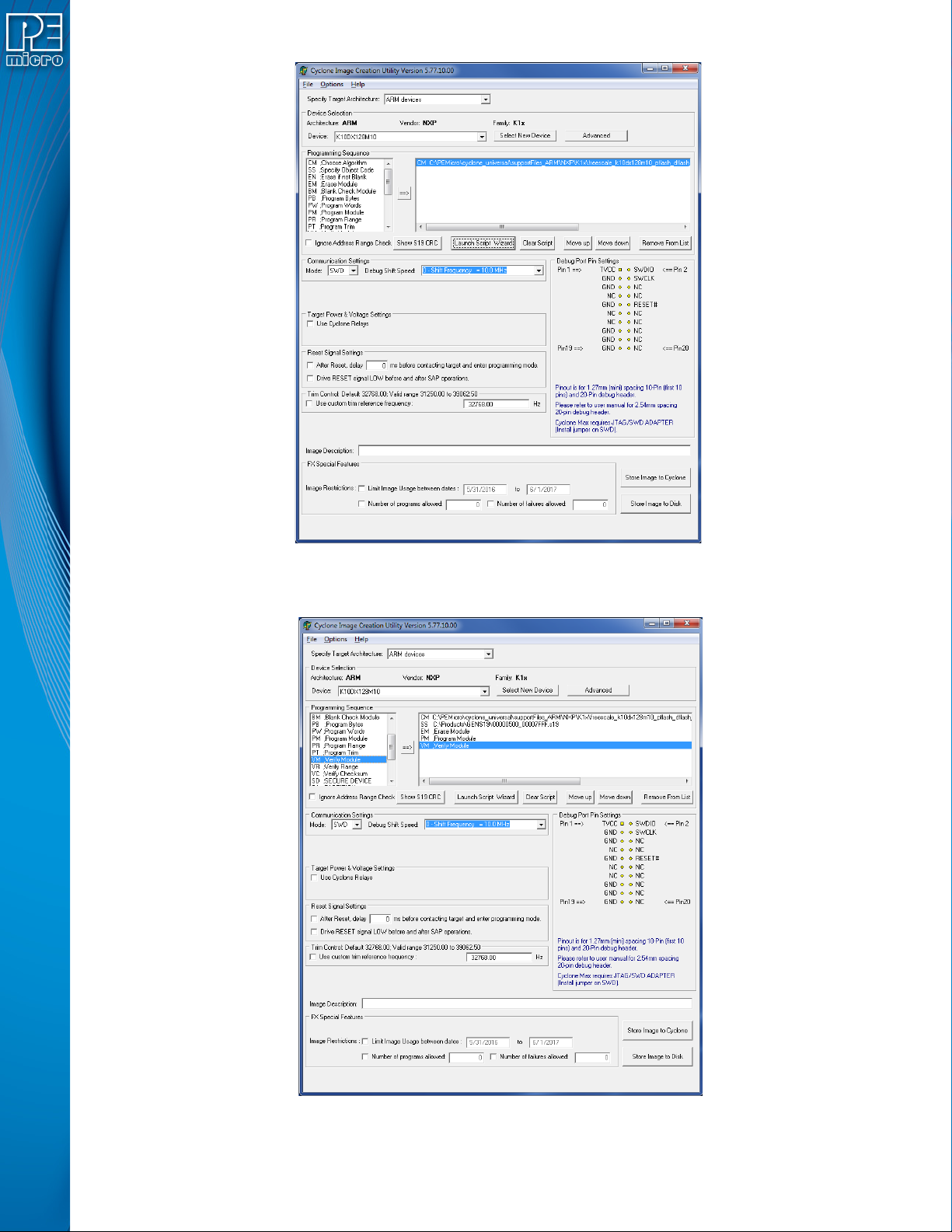
Figure 6-7: Programming Functions Enabled
Next, the user should add additional programming functions to complete the programming script.
Figure 6-8: Programming Functions Complete
User Manual For CYCLONE FX Programmers 38
Page 44
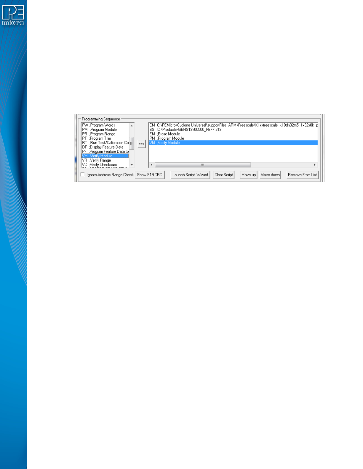
The Launch Script Wizard button prompts the user for a programming module, followed by an SRecord, and creates a default programming script. The user can then modify the programming
sequence as needed.
The Clear Script button will remove all programming commands from the right panel.
The Move Up and Move Down buttons allow the user to manually re-sequence the order of the
programming commands.
The Remove From List button can be used to remove a selected command from the right panel.
At this point the image can be saved to a disk or to the Cyclone device. For more information,
please see Section 6.1.8 - Store Image To Cyclone.
6.1.3 Programming Operations
Figure 6-9: Programming Operations Dialog Section
In the Programming Sequence field, the user may specify the algorithm, S-Record, and operations
to be carried out.
6.1.3.1 Choose Module
Presents a list of available programming files. Each programming file contains information on how
to program a particular module. Usually, the name of the file indicates what kind of module it
relates to.
6.1.3.2 Specify S-Record
Asks for the name (and/or path) to a file of S-records to be used in programming or verifying a
module. If the file is not found, an error message is given. The currently-selected file is shown in
the S19 file selected window. The programmer accepts S1, S2, and S3 records. All other file
records are treated as comments. If you do not specify a file-name extension, .S19 is used by
default. The programmer also supports ELF/Dwarf 2.0, 3.0, and 4.0 object files.
Your S19 file may contain data for both EEPROM and flash. If you know that your S19 file contains
the correct data, “Ignore S19 Range” may be checked. This will cause any out of range errors to be
ignored.
6.1.3.3 Erase If Not Blank
This command performs a blank check of the module and erases it if it is not blank.
6.1.3.4 Erase Module
If “Erase Module” is specified, the Cyclone will erase the EEPROM/flash on the target device after
entering the Monitor Mode or BDM mode.
6.1.3.5 Blank Check Module
If “Blank Check Module” is checked, the Cyclone will check to see if the flash/EEPROM on the
target device is erased.
User Manual For CYCLONE FX Programmers 39
Page 45
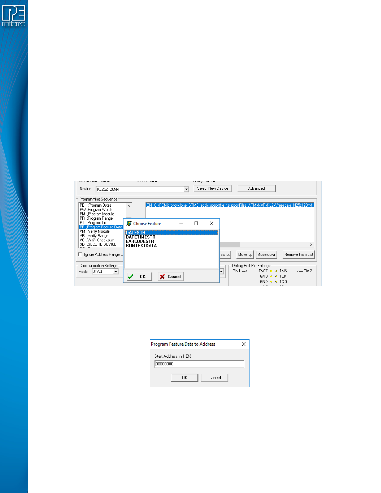
6.1.3.6 Program Bytes
Prompts for a starting address, which must be in the module. You are then asked to enter in
hexadecimal a byte to be programmed into the current location. Clicking the OK button will
automatically advance to the next data byte location.
6.1.3.7 Program Words
Prompts for a starting address, which must be in the module. You are then asked to enter, in
hexadecimal, a word to be programmed into the current location. Clicking the OK button will
automatically advance to the next data word location.
6.1.3.8 Program Module
This command will program the selected S-record file into EEPROM/flash. For this command to
work, you must have previously selected an S-record file.
6.1.3.9 Program Feature Data
The Program Feature Data option on the Cyclone Image Creation Utility gives the user more
options to program dynamic data programming on the target device. To use Program Feature Data
select the "PF" command when creating a programming image. A window will show you the
options for feature data to program.
Figure 6-10: Using PF Command (Dynamic Data)
The options can be 1) a string of the current date (YYYY-MM-DD), 2) a string of the current date
and time, 24-hour clock (YYYY-MM-DD HH:MM:SS), 3) run test data. To 4) program the barcode
into the flash of the target device, BARCODESTR should be selected. The next window contains
the hex address of where the dynamic data will be stored:
Figure 6-11: Program Feature Address Dialog (Hex)
6.1.3.10 Verify Module
This command will verify that the selected S-record file was programmed into the EEPROM/flash.
For this command to work, you must have previously selected an S-record file.
6.1.3.11 Verify Checksum
This command verifies the module content via a CRC calculation. This command is typically much
User Manual For CYCLONE FX Programmers 40
Page 46
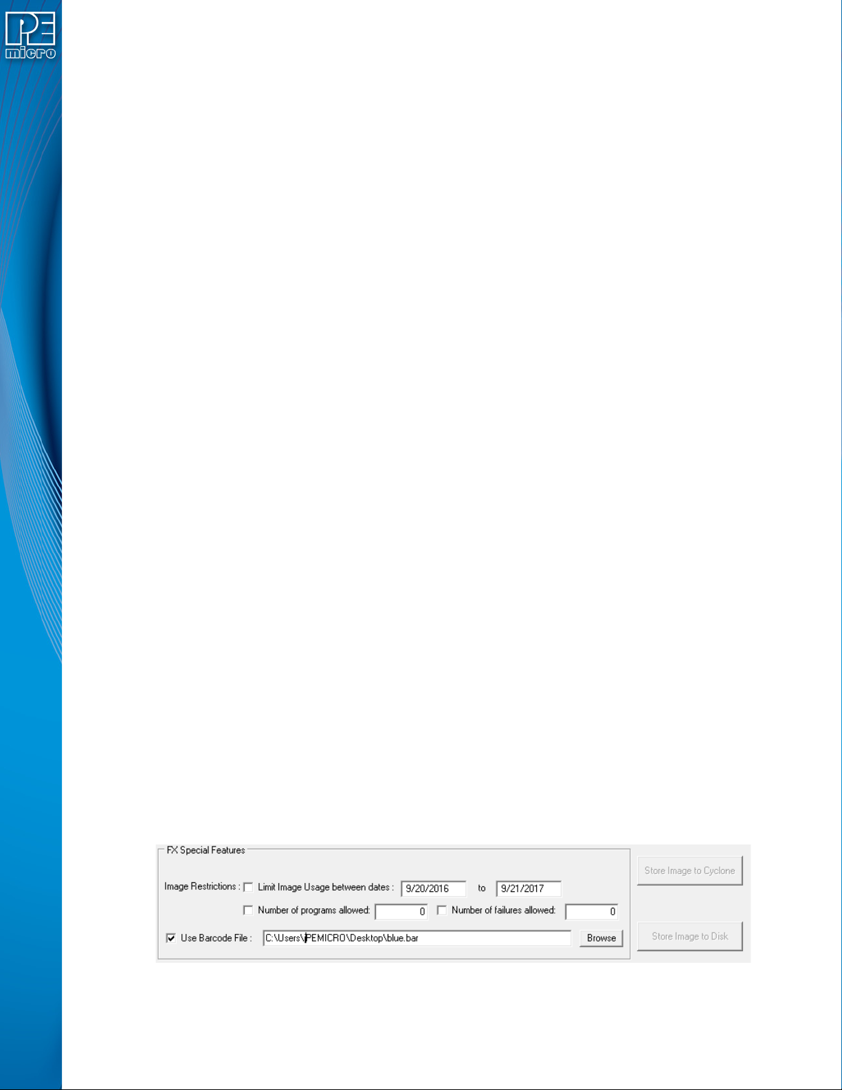
faster than performing a full Verify Module command.
6.1.3.12 Choose Serial File
This command becomes available once a programming algorithm is selected. It specifies the serial
file that holds the serial numbers to be programmed to the target.
6.1.3.13 Program Serial Number
This command becomes available once a programming algorithm is selected. It will instruct the
Cyclone to program the serial number to the target once executed. As with other commands, the
serial number will not be programmed until the SAP operations are carried out.
Note: When using a barcode scanner as part of the programming process, a Barcode Test file must be
included with the programming script of the SAP image. The “Use Barcode File” selection is
enabled, and the exact file specified, in the FX Special Features section of this window. Please
refer to Section 6.1.7.2 - Use Barcode File, and for more information on using a barcode scanner
with the Cyclone FX please see CHAPTER 11 - USING A BARCODE SCANNER TO SELECT
AN IMAGE & INITIATE PROGRAMMING.
6.1.4 Communication Mode and Rate Settings
CYCLONE FX programmers support multiple communication modes and communication rates. A
user needs to select proper communication mode and rate from the drop down list after
programming operations are specified. The debug connector pin definitions are listed for
reference.
6.1.5 Target Voltage and Power Settings
A user may elect to use Cyclone to supply power to the target. In this case, the Target Voltage
specifies the target MCU I/O voltage level.
The user needs to take into account the power discharge time for the Power Down delay. The
reset driver delays, power stabilization time, and the target clock stabilization time should be
considered for the Power Up delay.
A checkbox is available for a user to instruct the Cyclone to turn off target power after SAP
operations. If unchecked, the target power will remain on.
The user has the option to provide Reset Delay if certain reset monitoring devices are used. The
Cyclone will delay for the specified time after allowing the target out of reset.
6.1.6 Image Description
The Cyclone Image Creation Utility allows the user to summarize the purpose of current
configuration for future reference. The description will be either programmed into the Cyclone or
saved into an encrypted file.
The image description will appear on the touchscreen LCD for image identification. This field will
not affect the Cyclone’s operations with the target.
6.1.7 FX Special Features
The CYCLONE FX includes additional security and other settings which may be configured here:
Figure 6-12: FX Special Features
User Manual For CYCLONE FX Programmers 41
Page 47

6.1.7.1 Image Restrictions (Enhanced Security Settings)
There are any number of reasons why the user may want to place restrictions on the use of
specific programming images on a Cyclone programmer: from added ease when managing
production to a desire to protect intellectual property. When using the CYCLONE FX, the “FX
Special Features” section of the Cyclone Image Creation Utility allows you to specify one or more
restrictions and tie them to specific programming images. Even if restricted programming images
are deleted from Cyclone’s internal memory or an SD card, the Cyclone platform has a persistent
memory that continues to tie security restrictions to that programming image. Thus, if an image is
removed and re-added to a Cyclone, the image counts are maintained and would continue
counting from where it left off. Also, if the SD Card is moved from Cyclone to Cyclone, the count is
maintained in both Cyclones as well as the SD Card.
Every time an image is generated by the Cyclone Image Creation utility, it is encoded with a unique
image ID number. All counts are stored relative to this unique ID number. So, when an image is
regenerated in the Cyclone Image Creation utility, it will have its own counts which will not conflict
with the previously generated image, even if the images are otherwise exactly the same. In this
way, the user can regenerate an image to allow a new batch of targets to be programmed.
Note: The user may set more than one type of restriction on a programming image. The ability to
program the image will be restricted by whichever triggers first. E.g., if the user creates settings to
allow 100 programs, and also sets an allowed date range restriction, the ability to program the
image will be restricted as soon as the first of these conditions is triggered.
Currently the user may set the following restrictions:
6.1.7.1.1 Limit Image Usage Between Dates
When “Limit Usage Between Dates” is checked and the start and end dates are specified with valid
dates (format: DD/MM/YYYY), the Cyclone operator will only be allowed to program the
corresponding programming image when the date is on or between the dates specified. The
Cyclone has an onboard battery and clock which keeps a clock running even when power to the
Cyclone is removed. This clock date is the one used for comparison to the UTD Date specified in
the image. The ability to limit programming to a date is useful for making sure that an image will
stop working after a period of time. This could be for security purposes, or to make sure that a new
and updated image will need to be uploaded to the Cyclone after a period of time (for instance, to
not allow a firmware more than a year old to be programmed onto a target).
6.1.7.1.2 Limit Number of Programs Allowed
When “Limit Number of Programs Allowed” is checked and a number is specified in the
corresponding box (minimum = 1), the Cyclone operator will only be able to execute a number of
successful programming operations of this programming image less than or equal to the number
specified. The current programming count can be displayed on the main screen of the Cyclone or it
can be seen on the image's statistics page (see Section 6.1.7.1.4 - Image Restriction
Statistics).
6.1.7.1.3 Limit Number of Failures Allowed
When “Limit Number of Failures Allowed” is checked and a number is specified in the
corresponding box (minimum = 1), the Cyclone operator will only be able to execute programming
operations on the current image until the maximum number of errors specified has been reached.
This restriction exists largely to prevent an operator from intentionally generating an error as part
of the programming process in an attempt to circumvent the count restrictions. A recommended
limit on this number would be on the order of 5% of the allowed programming counts.
6.1.7.1.4 Image Restriction Statistics
Statistics related to any specified restrictions for the currently selected programming image may
viewed by navigating in the touchscreen menu to Current Image Operations - Show Current Image
Stats. For more information on viewing programming image stats, see Section 5.2.2.4 - Show
Current Image Stats (FX Only).
In addition, the statistics for Number of Programs & Maximum Allowed can be set to display on the
User Manual For CYCLONE FX Programmers 42
Page 48
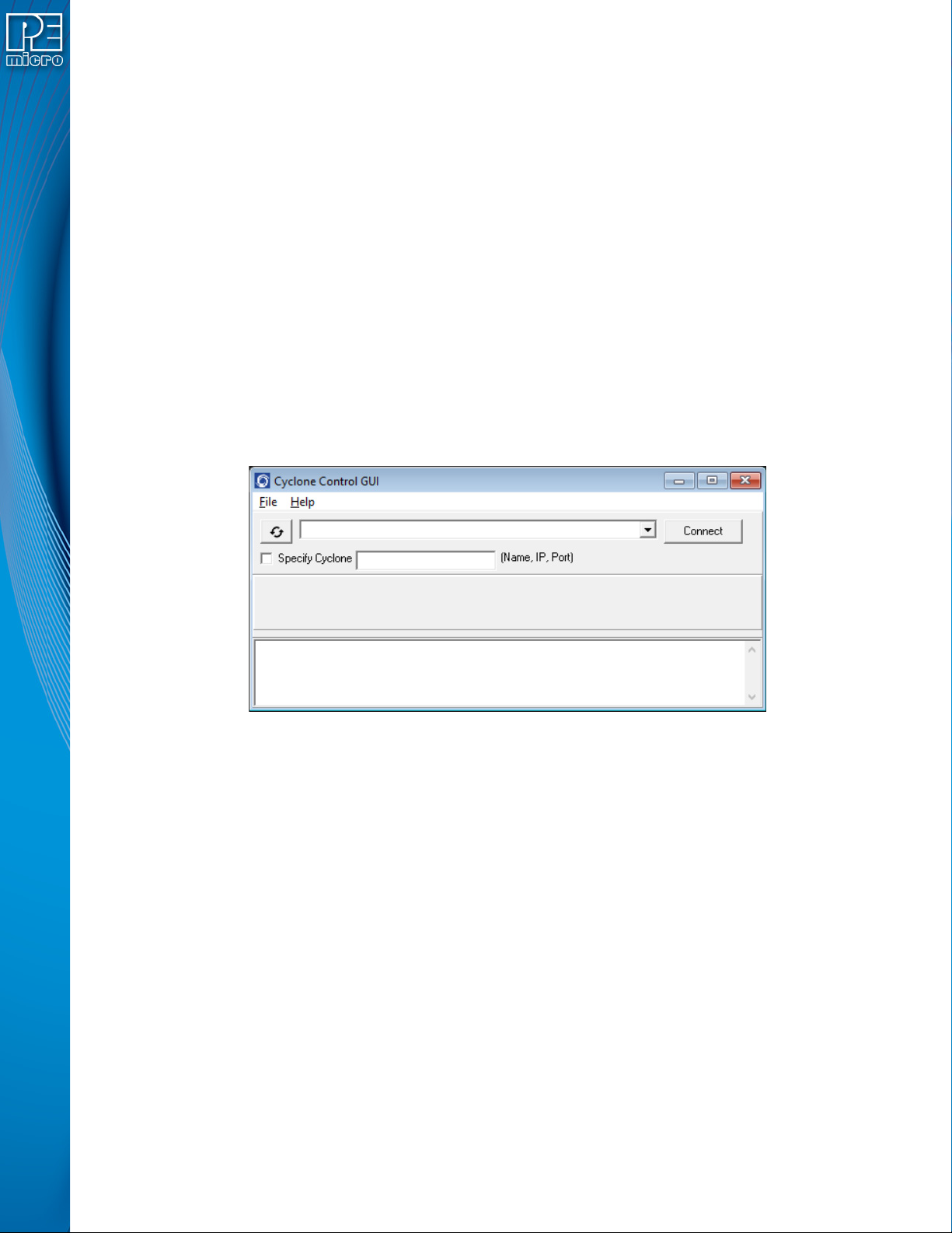
home screen by navigating in the touchscreen menu to Configure Cyclone Settings -> Configure
Screen -> Configure Home Screen. For more information on how to configure the Cyclone’s home
screen, see Section 5.2.3.5.4 - Configure Home Screen.
6.1.7.2 Use Barcode File
PEmicro’s Cyclone FX programmers can be configured to use a bar code scanner (connected to
the extension port) as part of the programming process. During setup the user will create a
Barcode Test file using the provided Barcode Test Generator utility.
Here, the user should then check the Use Barcode File checkbox if they wish to include a Barcode
Test file in the programming script of their SAP image. The user can then Browse to the file they
wish to select. This is required when using the bar code scanner as part of the programming
process. For more information on how to incorporate a barcode scanner into the Cyclone’s
programming process, please see CHAPTER 11 - USING A BARCODE SCANNER TO SELECT
AN IMAGE & INITIATE PROGRAMMING.
6.1.8 Store Image To Cyclone
“Store Image to Cyclone” allows the current configuration to be programmed into the Cyclone. The
Cyclone will then be ready for operations. After you click “Store Image To Cyclone,” the Cyclone
Control GUI will pop up so that you can choose the Cyclone onto which you wish to save the SAP
image.
Figure 6-13: Cyclone Control GUI: Choose Cyclone for Stored Image
The Cyclone Control GUI drop-down list allows the user to select from all the Cyclones available.
In the case of a Cyclone present on a different network (i.e., not displayed automatically in the
drop-down list), the user may specify its IP address by using the Specify Cyclone checkbox and
typing the identifier of the Cyclone.
Click on "Connect" to access the specified Cyclone. A click on the "Apply Changes" button will
then store the image on the selected Cyclone.
6.1.9 Store Image To Disk
“Store Image To Disk” allows the current configuration to be saved onto the hard drive. The image
can then be transferred to the Cyclone’s internal flash (or an installed SD card) via the Manage
Images Utility.
6.1.10 Save Cyclone Configuration
“Save Cyclone Configuration,” in the file menu, allows the user to save the configuration into a file,
which may be used for future reference, e.g., comparing the Cyclone contents with the file to see if
they are the same.
6.1.11 Load Cyclone Configuration
“Load Cyclone Configuration” in the file menu allows the user to load a configuration that has
User Manual For CYCLONE FX Programmers 43
Page 49
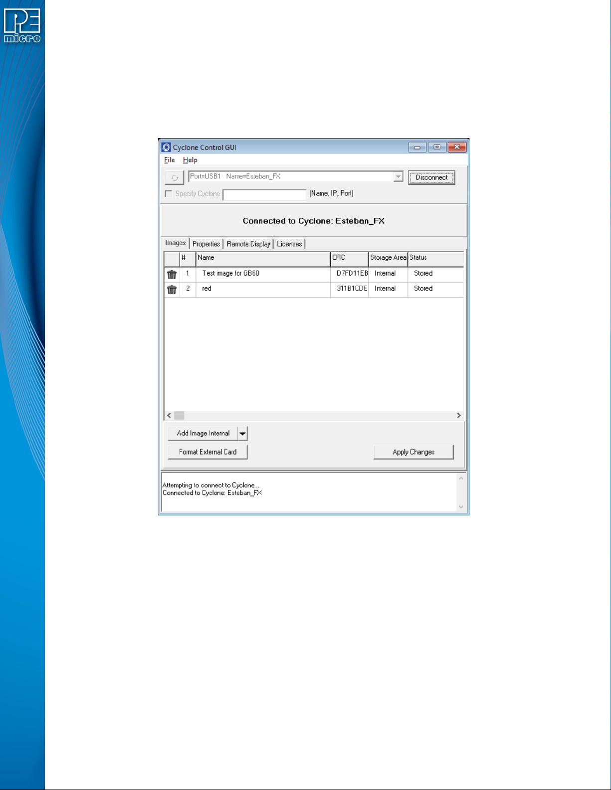
previously been saved in order to create a new image.
6.2 Manage Multiple SAP Images
The Cyclone Control GUI, shown below in Figure 6-14, allows the Cyclone to store and manage
multiple images in the Cyclone’s internal memory, and on any compatible SDHC cards that are
loaded into the SDHC port. Once the programming images have been created and saved to the
disk using the Create Image utility, they may then be loaded collectively onto the Cyclone.
Figure 6-14: Manage Images Utility
Upon opening a selected Cyclone in the Cyclone Control GUI, the user is provided in the first tab
with a list of the images currently on the unit’s internal memory which are marked with a Storage
Area label of "Internal". A list of images on any installed SDHC card will also be displayed with a
Storage Area label of "External"
You can add images with the "Add Image Internal" button under the images panel. These images
will appear with a "Status" label of "Ready to Store". These images are not yet in the Cyclone, the
"Apply Changes" button will have to be clicked for the changes to take effect.
If the Cyclone’s SDHC port is activated, the user can also add images to the external memory by
using the drop-down next to the "Add Image Internal" button and selecting "External". Alternatively,
once an image has been added to the proposed changes and it is in the "Ready to Store" state, the
user may right click on the image and click the "Switch storage to External" option.
6.2.1 Delete Images From Internal/External Memory
Any images that are already stored on the Cyclone or installed SD card can be deleted by just
clicking on the trash can on the left of the image or by selecting the image and clicking the Delete
User Manual For CYCLONE FX Programmers 44
Page 50

key on the keyboard, the image status will be changed to "Ready to Erase.” The image will be
removed after "Apply Changes" is clicked.
6.2.2 Add/Remove Images From The Commit Changes Panels
Once the images that you wish to load appear in the images tab, you must press “Apply Changes”
to update the Cyclone accordingly. No actual updates will occur to the Cyclone’s internal/external
memory or installed SD card until the user selects “Apply Changes.
Note: Any SAP images that are already stored on older Cyclone models such as the Cyclone PRO,
MAX, Renesas, STMicro or Cyclone ACP Rev. A/B (or on a CompactFlash card in one of those
units, if applicable) can not be removed individually and can only be erased by removing all
images.
User Manual For CYCLONE FX Programmers 45
Page 51

7 CYCLONE PROGRAMMER MANUAL CONTROL
The CYCLONE FX must be configured before it can serve as a Stand-Alone Programmer. The
user may manually control the Cyclone via the LCD touchscreen menu and/or the Start button, or
via PC software. See CHAPTER 8 - CYCLONE PROGRAMMER AUTOMATED CONTROL
(CYCLONE CONTROL SUITE) for information on how to use the Cyclone Control Suite to
configure, control, and automate Cyclone operations. The target power management schemes
remain the same for each control method.
7.1 Operation Via Start Button
There is a Start button on the top of the Cyclone which is used for stand-alone programming. It is
specified as follows.
Button Function
START Start executing the tasks pre-configured into the Cyclone of the currently
selected programming image.
7.1.1 LED Indicators
The Cyclone has two (2) LEDs to indicate the current operation stage.
LED FUNCTION
Error The Cyclone failed to execute the functions as instructed.
Success The Cyclone executed the functions successfully.
7.1.2 Procedure via Start Button / LEDs
The following steps must be followed in order for the Cyclone to operate properly after it has been
configured:
1. Turn off the target power supply if the “POWER IN” Jack is adopted.
2. Turn off the Cyclone system power.
3. Set the correct Power Management jumper settings.
4. Connect the target power supply to the “POWER IN” Jack, if applicable.
5. Connect the “POWER OUT” Jack to the target board power, if applicable.
6. Connect the ribbon cable to the target board debug connector.
7. Turn on the Cyclone system power.
8. Turn on the target power supply, if applicable.
9. Press the “START” button on the Cyclone.
When the “Success” LED lights up, you have successfully programmed your target.
7.1.3 Example
After the user programs the contents and procedures into the Cyclone’s on-board flash, the
Cyclone may be used as a Stand-Alone Programmer. Suppose the user wants to perform the
following instructions for a target device:
1) Erase Module
2) Program Module
3) Verify Module.
If the Cyclone is providing power to the target board, the “Target Power” icon will illuminate on the
LCD display.
The Cyclone will then perform the operations. If they are performed successfully, the “Success”
LED will be illuminated. One stand-alone programming cycle will have just been completed.
User Manual For CYCLONE FX Programmers 46
Page 52

7.2 Operation Via LCD Touchscreen Menu
Once the CYCLONE FX is configured for stand-alone programming it may be operated by making
selections from the touchscreen LCD menu. This section describes the menu functions that allow
the user to easily execute stand-alone programming functions using the touchscreen LCD.
7.3 Home Screen
The home screen appears when the Cyclone is powered on, or when the Home button
is tapped.
7.3.1 Icons
A row of icons in the upper right corner indicates the status of various attributes of the Cyclone.
Note: The user may tap on the row of icons to view the meaning of each of the currently displayed icons.
Real-Time clock Enabled & Working: Yes / No
SDHC Memory Card: None / Valid / Unformattted / Reset Cyclone**
* Target Device Is Powered - “Yes” indicates that the CYCLONE FX detects power on the Vcc pin
of the target device programming header.
** SDHC Memory Card - “Reset Cyclone” indicates that the Cyclone needs to be reset before the
SDHC card will register as Valid. The user can push the Reset button which is located on the front
side of the Cyclone, below the LED indicators.
7.3.2 Configurable Display Area
The main area of the home screen can be configured to optionally display the following
information, by using the Cyclone IP Configuration Utility (see Section 5.2.3.5.4 - Configure
Home Screen):
1. Firmware version of the Cyclone (always shown).
2. IP address assigned to the Cyclone.
3. Name assigned to the Cyclone.
4. Number of programming images in the Cyclone’s memory.
Cyclone Unit Status: Ok / Bad
Programming Status: Ready / Busy
Target Power Relays: On / Off
USB-To-PC Enumerated: Yes / No
Cyclone Power Relays: Closed / Open
Target Device Is Powered*: Yes / No
Barcode Scanner: Detected / Not Detected
5. Name of the selected programming image.
6. First serial number associated with the selected image
7. Current status.
8. Results of the last operation performed.
9. Time and date.
10. Status Window and Main Menu button (always shown).
11. Target voltage and/or current
User Manual For CYCLONE FX Programmers 47
Page 53
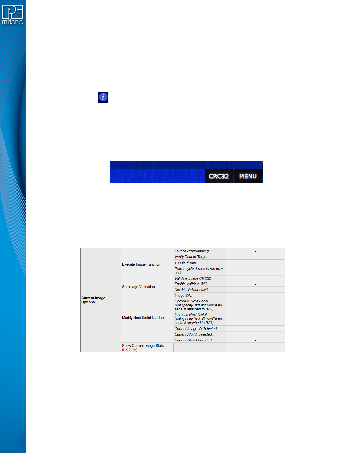
12. Programming count & limit
7.4 Status Window
The status window appears in the lower left corner of the home screen and displays the results of
programming operations.
7.4.1 Error Information Icon
When the Cyclone experiences an error during programming operations, the Info icon will appear
to the left of the Menu button (or AUX button, if configured).
Info Icon:
Press the Info icon to view a detailed description of the error.
7.4.2 AUX Button (Appears If Configured)
The Cyclone allows the user to add an Auxiliary (AUX) button to the home screen which will
perform a specific function when pressed. The specific function is chosen by the user when the
AUX button is configured. The AUX button will appear on the home screen to the left of the “Menu”
button, in the lower right corner of the home screen.
Figure 7-1: AUX Button On Home Screen (configured for perform CRC32 function)
For information on how to configure the AUX button, see Section 5.2.4 - Status.
7.4.3 Main Menu
The Main Menu is accessible by pressing the “Menu” button when the Home Screen is displayed.
The Main Menu screen contains four selections. From these, select “Current Image Options.”
Figure 7-2: Touchscreen LCD Menu - Standalone Functions Highlighted
The menu selections in “Current Image Options” will allow the user to execute programming
operations, verify data, toggle power, validate the programming image, and modify the upcoming
serial number if necessary.
7.4.3.1 Execute Image Function
Execute Specific SAP Function presents four Stand-Alone Programming functions that you may
execute by tapping the function that you wish to execute:
User Manual For CYCLONE FX Programmers 48
Page 54

7.4.3.1.1 Launch Programming
This allows the user to execute the programming function. The Cyclone will program the target
device, if able, using the currently selected programming image. This is functionally equivalent to
pressing the Start button.
7.4.3.1.2 Verify Data In Target
Performs a verify function on the data that has been programmed into the target device.
7.4.3.1.3 Toggle Power
Toggles the target power and makes sure all ports are driven to debug mode level.
7.4.3.1.4 Power Cycle Device To Run User Code
Toggles the target power and maintains tri-state mode for all signals.
7.4.3.1.5 Validate Image CRC32
Allows the user to perform a CRC32 validation on the currently selected programming image.
7.4.3.2 Set Image Validation
Allows the user to choose between two validation settings: 1) validate the image each time the
Start button is pressed, or 2) do not validate the image.
7.4.3.3 Modify Next Serial Number
Presents options that display the current serial number and allow the user to increase or decrease
the next serial number. Tap “Current Image ID Selected” to view/choose the desired programming
image; tap “Current Alg ID Selected” to view/choose the desired programming algorithm; use
“Current CS ID Selected” to view/choose the desired Choose Serial file. The adjustment buttons
will display “Increase Not Allowed” and “Decrease Not Allowed” if the image/algorithm/CS files that
the user has selected to do not allow for this operation.
7.4.3.4 Show Current Image Stats
Displays current statistics, if any, for Image Programmed Count & Maximum Allowed, Errors
Logged & Maximum Allowed, and Date Range Allowed. These limits can be set in the Image
Creation Utility.
Note: When Current Image Stats is displayed as a home screen item, only Image Programmed
Count & Maximum Allowed are displayed on the home screen.
User Manual For CYCLONE FX Programmers 49
Page 55

8 CYCLONE PROGRAMMER AUTOMATED CONTROL (CYCLONE CONTROL
SUITE)
Users who wish to control, configure, and automate one or more Cyclone units have several
options available. This chapter presents a brief overview of those options along with some
additional information about each.
8.1 Overview Of Cyclone Control Suite
The Cyclone Control Suite is a new generation of automated control software developed to support
PC based control of the popular Cyclone and Cyclone FX stand-alone programmers.
The suite provides comprehensive control of one or more Cyclones from the PC via the following
components: the Cyclone Control GUI application, the Cyclone Control Console application, or via
custom applications using the Cyclone Control SDK. Ways to control the Cyclone include
programming launch, recovering results, managing images resident on a Cyclone, adding unique
programming data for each target, as well as recovering descriptive errors.
Much of the cyclone control feature set works for all touchscreen Cyclones. Advanced features
require a Cyclone-resident Advanced Automation License which comes built into the Cyclone FX
and is available as an upgrade for all other touch screen Cyclones.
8.1.1 Components
The Cyclone Control Suite consists of three major components:
1. Cyclone Control SDK – This is a Software Development Kit with a comprehensive API
allowing multiple Cyclones to be managed simultaneously from a user developed custom
application that loads the provided Cyclone Control DLL. The DLL can be loaded from
many programming languages that are able to load a DLL (C, Delphi, C#, Java, Python,
etc) as well as environments such as LabVIEW. Examples and interface code are provided in C (MSVC and GCC), C#, and Delphi/FPC. See Section 8.2 - Cyclone Control
SDK.
2. Cyclone Control Console – This is a powerful command-line application can be launched
from a script, a command-line, or another application and allows control of one or more
Cyclones simultaneously. The command-line application displays comprehensive status
messages and also returns an error code which can be recovered from the calling application. See Section 8.3 - Cyclone Control Console.
3. Cyclone Control GUI – This is an interactive GUI based application which provides an
easy way to control Cyclones and manage images resident in the Cyclones. Given its
graphical nature, it is very easy to explore Cyclone Control Suite capabilities to intuitively
control or interact with a Cyclone. See Section 8.4 - Cyclone Control GUI.
The Console and GUI were both built with the SDK and are good examples of the types of
applications which can be built using the SDK.
Additional sample applications come as part of the installation. They contain defined build scripts
that you should be able to use to build the sample application without any modifications.
8.1.2 Features
The SDK, Console, and GUI control applications provide the following Standard features for all
Cyclones:
• Control a Cyclone via USB, Serial, or Ethernet connections
• Select and Launch Images by Name or Enumeration
• Recover programming result and descriptive error information
• Use automatically counting local (Cyclone stored) serial numbers
• Add/Remove/Update a single image in the Cyclone
• Read/write Cyclone properties
User Manual For CYCLONE FX Programmers 50
Page 56

• Read Image and target Properties and Status
The GUI application provides the following Advanced features for all Cyclones:
• Add/Remove/Update many images in the Cyclone
• Remote Display Access and the ability to “touch” the screen
These features require an Advanced license only when using the SDK or Console (see below).
The SDK and Console application provide the following Advanced features for all Cyclone FX units
and any Cyclone upgraded with a resident Cyclone Control Advanced Automation License:
• Add/Remove/Update many images in the Cyclone
• Simultaneously (Gang) Control multiple Cyclones via the USB, Serial, or Ethernet
connections
• Program (and Read) Dynamic Data in addition to fixed image data
• Remote Display Access
8.1.3 PEmicro Compatible Hardware
The following lists the PEmicro hardware that is compatible with the Cyclone Control Suite. To
ensure proper operations, PEmicro recommends upgrading all Cyclone units to the latest
firmware.
• Cyclone Universal FX
• Cyclone Universal
• Cyclone ACP FX
• Cyclone ACP
• Cyclone PRO (Standard features only)
• Cyclone MAX (Standard features only)
• Cyclone for ARM (Standard features only)
• Cyclone for Renesas (Standard features only)
• Cyclone for STMicro (Standard features only)
8.2 Cyclone Control SDK
The Cyclone Control SDK allows the user to interact with the Cyclone via a .DLL.
8.2.1 Introduction
The Cyclone Control SDK is one of the three components that comprise the Cyclone Control Suite.
Its dynamic link library (.DLL) allows you to create an application on the PC that can directly control
one or more PEmicro Cyclone units. These interface routines are designed to be compiled into
visual and non visual applications running on Windows operating systems
The actual interface routines are located in the “CycloneControlSDK.dll” 32 bit DLL file. The DLL
is callable from almost any 32-bit / 64-bit Windows development environment. Since the way the
DLL is called varies depending on the compiler used, you are provided with the DLL interface code
and sample applications for each of the following compilers. Compilers in bold link to a PEmicro
blog post about using that environment with the SDK:
Borland Delphi 2.0+ (Pascal)
GCC
Microsoft Visual C
Microsoft Visual C#
NI LabVIEW 2018
User Manual For CYCLONE FX Programmers 51
Page 57

The sample applications come with build scripts defined for ease of use. Simply run the scripts and
you should be able to build the sample application without any modifications. The callable interface
routines are defined in:
INSTALLDIR\cycloneControl\controlsdk\examples\pascal\cyclone_control_api.pas
INSTALLDIR\cycloneControl\controlsdk\examples\c\cyclone_control_api.h
8.2.2 Backwards Compatibility With Classic Cyclone Control API
The “CycloneControlSDK.dll” is backwards compatible with many of the classic Cyclone Control
API calls. In each header file, there is a constant variable or define (typically DLL_filename) which
is declared as the file name of the DLL. The value of this variable should be changed to new
filename “CycloneControlSDK.dll” instead of the old "CYCLONE_CONTROL.dll". After this
modification, rebuild the project and it should continue working with the new DLL.
8.2.3 Getting Started with the Cyclone Control DLL
This section outlines the steps you need to take to begin developing your own custom application
and offers tips and suggestions to get the Cyclone Control DLL working with your PEmicro
hardware smoothly.
BLOG TIP: Please click here to visit the PEmicro blog for a detailed example of how to set up a
programming image and use the SDK with some advanced options.
8.2.3.1 Example Programs
Located in the installation directory of the package, you will find two example programs that you
can use as a reference for your own application. The examples are located in the following
directories:
INSTALLDIR\cycloneControl\controlsdk\examples\pascal\
INSTALLDIR\cycloneControl\controlsdk\examples\c\
These example programs are a valuable reference to use when starting your own custom
application.
8.2.3.2 Starting your own project
To gain access to the functions available in the DLL, the following files need to be added to the
new project workspace:
UDelphi 2.0+ Projects
INSTALLDIR\cycloneControl\controlsdk\examples\pascal\cyclone_control_api.pas
All other source files which will call functions from the DLL should include the above file using the
Delphi “uses” command.
UMSVC 5.0+ Projects
INSTALLDIR\cycloneControl\controlsdk\examples\c\cyclone_control_api.h
INSTALLDIR\cycloneControl\controlsdk\examples\c\cyclone_control_api.c
All other source files which will call functions from the DLL should include the above header file
with the C/C++ #include directive.
MSVC# 2017 Projects
User Manual For CYCLONE FX Programmers 52
Page 58

INSTALLDIR\cycloneControl\controlsdk\examples\msvcsharp\visual_sap_control\cyclone_control
_api.cs
NI LabVIEW 2018 Projects
INSTALLDIR\cyclone\cycloneControl\controlsdk\examples\labview2018\user.lib\CycloneControlS
DK\CycloneControlSDK.lvlib
INSTALLDIR\cyclone\cycloneControl\controlsdk\examples\labview2018\user.lib\CycloneControlS
DK\VIs\*.vi
The pre-built VIs that we provide include modifications for error handling using error clusters.
Please visit our blog post “Automated Flash Programming with LabVIEW” for more information on
how to develop your own LavVIEW project.
8.2.3.3 Initialization
ULoading the DLL (C/C++ Projects only)
Before calling any routines from the DLL, the DLL must be loaded into memory. To do this, the
following function has been provided in the included header files. Refer to Chapter 4 of this manual
for a detailed description of this function.
loadLibrary( );
For Delphi (Pascal) and C# users, this process is transparent for the user and no action is
required.
UEnumerate all ports
After loading the DLL, a call to the following function is required in order to properly initialize all
devices. This function should only be called once, typically at the beginning of the application.
enumerateAllPorts( );
UConnect to the PEmicro hardware interface
The next step is to establish communications with the PEmicro Cyclone unit. This is accomplished
with the following function call:
connectToCyclone( );
Refer to Chapter 4 of this manual for a detailed description of this function. This call returns the
handle to the Cyclone unit which is used in all other routines in the DLL to identify the Cyclone.
Note that the special case of a return value of 0 indicates an error contacting the Cyclone. This
function will be called once for each Cyclone.
User Manual For CYCLONE FX Programmers 53
Page 59
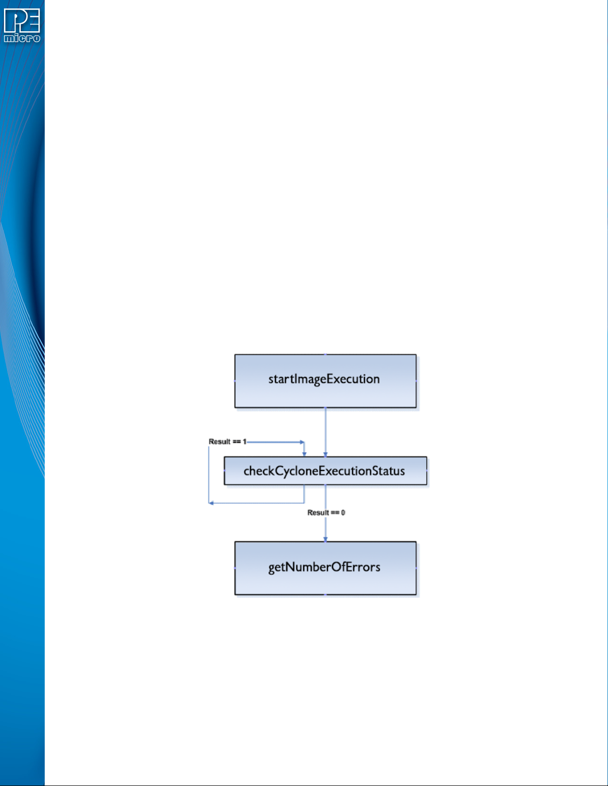
8.2.3.4 Finalization
Before closing the application, it is recommended that the session with the PEmicro hardware be
terminated and the DLL unloaded from memory.
These calls should always be made before the application closes:
disconnectFromAllCyclones( );
unloadLibrary();
Note that the “unloadLibrary” call is only required for C/C++ applications. For the Delphi and C#
example projects, the DLL is automatically unloaded when the application closes.
8.2.3.5 Initial Cyclone Setup
The Cyclone Image Creation Utility software, which is included with each Cyclone, is used to
create the standalone images that will be stored in the non-volatile memory of the Cyclone. These
images contain the FLASH / EEPROM programming algorithms, the actual binary data to be
programmed, the sequence of programming operations, and user specified Cyclone settings.
Prior to using the Cyclone Control Suite, these standalone images need to be created. Please
refer to the user’s manual of your Cyclone unit for more information on standalone images and
image creation.
8.2.3.6 Typical Usage
Figure 8-1: Typical programming procedure flow chart
Figure 8-1 describes the most common sequence of calls to the DLL after successfully connecting
to the Cyclone unit.
a. Initiate programming operations. “startImageExecution” carries out the programming
operations defined in the stand-alone image stored on the Cyclone unit.
b. Wait for programming completion. Note that no error checking is provided by the
“checkCycloneExecutionStatus” call. A result of 0 will be returned even if an error has
occurred or if communication with the Cyclone is lost.
User Manual For CYCLONE FX Programmers 54
Page 60
c. Retrieve the error code from the Cyclone unit to determine if the programming was
successful.
8.2.3.7 External Memory Storage Support
Some Cyclones support external memory storage. The Cyclone Control SDK and Cyclone Control
Console both support images residing on external memory cards. The parameter
“selectedMediaType” is used to select between Cyclone internal Flash and external memory.
Image numbers will go in ascending order starting with image number 1. Internal images will be
counted first and external image numbers will start after the last internal image number. Image
number 1 will refer to the first image in the internal memory if there are any images in the Cyclone
internal memory, if there are no internal images, image 1 will refer to the first image in the external
memory.
Modifying images residing in external memory will only be available on Cyclones with the proper
license. Certain Cyclones may require a supplementary license to support external memory.
8.2.4 Application Programming Interface (API)
This chapter describes the API of the “CycloneControlSDK.dll” in detail. A C/C++ function
prototype is given here. Header files are provided for the following languages:
Pascal
C/C++
8.2.4.1 Constants
Name 32-bit Value
CyclonePortType_USB 5
CyclonePortType_Ethernet 6
CyclonePortType_Serial 7
CycloneInformation_IP_Address 1
CycloneInformation_Name 2
CycloneInformation_Generic_Port_Number 3
CycloneInformation_Cyclone_Type_String 4
MEDIA_INTERNAL 1
MEDIA_EXTERNAL 2
8.2.4.2 DLL Loading / Unloading Calls
8.2.4.2.1 loadLibrary
bool loadLibrary(char *filepath);
This function loads the CycloneControlSDK.dll into memory and gives the user access to all of the
functions available in the library. This routine must be called before any of the other routines
User Manual For CYCLONE FX Programmers 55
Page 61

can be called.
@returnvalue True if the load was successful, false otherwise.
8.2.4.2.2 unloadLibrary
void unloadLibrary(void);
This function unloads the DLL loaded with loadLibrary( ). This call should be made before the
application starts to unload itself.
8.2.4.2.3 enumerateAllPorts
void enumerateAllPorts(void);
This function performs all necessary initialization in order to successfully communicate with a
Cyclone. The function is called once before the first call to “connectToCyclone”.
8.2.4.2.4 disconnectFromAllCyclones
void disconnectFromAllCyclones(void);
This function closes all open Cyclones (if any) and frees all dynamic memory used by the DLL. The
function is called before the user application is closed.
8.2.4.2.5 version
char *version(void);
This call returns a pointer to a null-terminated string that contains the version number of the DLL.
@returnvalue A pointer to a null-terminated string containing the version number of the DLL.
8.2.4.2.6 queryNumberOfAutodetectedCyclones
uint32_t *queryNumberOfAutodetectedCyclones(void);
This function returns the number of Cyclones connected locally on USB and on your local network.
@returnvalue The number of Cyclones.
8.2.4.2.7 queryInformationOfAutodetectedCyclone
char *queryInformationOfAutodetectedCyclone(int32_t autodetectIndex, int32_t
informationType);
@parameter
autodetectIndex
User Manual For CYCLONE FX Programmers 56
Specifies the index of the detected Cyclone by the function
queryNumberOfAutodetectedCyclones()
Page 62

@parameter
informationType
Specifies the property of the Cyclone to return. The possible values
are:
• CycloneInformationation_IP_Address
• CycloneInfrmation_Name
• CycloneInformation_Generic_port_number
@returnvalue
8.2.4.3 Cyclone Connecting / Disconnecting Calls
8.2.4.3.1 connectToCyclone
A pointer to a null-terminated string containing the property value of
the specified Cyclone.
uint32_t connectToCyclone(char *nameIpOrPortIdentifier) ;
This function opens a session with a Cyclone and tests the connection. The handle returned by
this function is passed as a parameter to other functions provided by the DLL. If you connect to a
Cyclone that already has a handle, the same handle is returned. If there is a failure contacting the
Cyclone, the function returns a 0.
Note that the DLL does not support multiple Cyclones connected via the serial port. If you require
more than one Cyclone to use a serial port connection, PEmicro recommends using the RS232
communication protocols.
A pointer to a null-terminated string which uniquely identifies the
Cyclone connected to the host PC.
If identifying by IP address, the string should be in the format of
xxx.xxx.xxx.xxx, where xxx = 0…255.
If identifying by name, the string should contain the name of the
@parameter
nameIPOrPortIdentifier
@returnvalue
8.2.4.3.2 connectToMultipleCyclones
Cyclone.
If identifying by port and the Cyclone is connected by USB, the
string should be USB# where # is 1…8. If the Cyclone is
connected by Ethernet, the string should be in the format of
xxx.xxx.xxx.xxx, where xxx = 0…255.
If the Cyclone is connected by Serial, the string should be
COM1.
The handle to the opened Cyclone unit. A return value of 0
indicates a failure to connect to the specified Cyclone unit.
bool connectToMultipleCyclones(char *nameIpOrPortIdentifierArray,
multipleCycloneHandleArrayPtrType cycloneHandleArrayPointer, int32_t
*numberOfCycloneOpensAttempted);
This function returns a array of handles to opened Cyclones from a null-terminated String of
comma delimited identifiers.
User Manual For CYCLONE FX Programmers 57
Page 63

@parameter nameIpOrPortIdentifierArray
@parameter
multipleCycloneHandleArrayPtrType
A null terminated string containing one or more
Cyclone identifiers (name, IP address, or port
number) delimited by commas.
Example: USB1,209.1.10.2,Orion,COM1
If identifying by IP address, the string should be
in the format of xxx.xxx.xxx.xxx, where xxx =
0…255.
If identifying by port and the Cyclone is
connected by USB, the string should be USB#
where # is 1…8.
If the Cyclone is connected by Serial, the string
should be COM1.
A pointer to an array of Cyclone handles. Each
element of the array corresponds to the position
of the identifier in the previous parameter. If the
function connected to the Cyclone, the value of
the array element would correspond to its
handle otherwise it will be 0.
This value will be modified with the number of
@parameter
numberOfCycloneOpensAttempted
@returnvalue
8.2.4.3.3 setLocalMachineIpNumber
Cyclones that the function attempted to open. It
is also the size of the
multipleCycloneHandleArrayPtrType structure.
True if every Cyclone was identified and has a
valid handle.
False if there were any errors identifying or
connecting to any of the Cyclones.
void setLocalMachineIpNumber(char* ipNumber);
If a PC has multiple network interface cards, this function sets the IP address of the network card
to use communicate with the Cyclones. This is called prior to calling any other functions.
A pointer to a null-terminated character string in the format
@parameter ipNumber
xxx.xxx.xxx.xxx, where xxx = 0…255, representing the IP address of
the network card.
8.2.4.4 Controlling Cyclone Programming
8.2.4.4.1 startImageExecution
bool startImageExecution(uint32_t cycloneHandle, uint32_t imageId);
User Manual For CYCLONE FX Programmers 58
Page 64
A Cyclone may have several independent programming images in its non-volatile internal or
external memory. A programming image contains the programming algorithms, binary data, and
programming sequence. This function instructs the Cyclone to start execution of an image. After
invoking this call, the “checkCycloneExecutionStatus” function is used to poll the Cyclone until
completion.
@parameter cycloneHandle The handle of the Cyclone to begin programming operations
Selects the image on the Cyclone to use. The valid range of this
parameter is from 1 to the total number of images in the Cyclone
with the count starting from internal memory and then external
@parameter imageId
@returnvalue
8.2.4.4.2 startDynamicDataProgram
memory.
If a Cyclone only stores one image, this parameter is 1.
True if the programming process has started successfully.
False otherwise.
bool startDynamicDataProgram(uint32_t cycloneHandle, uint32_t targetAddress,
uint16_t dataLength, char *buffer);
Sometimes, in addition to the large amount of static data being programmed into a target from the
Cyclone, it is advantageous for the calling application to program small sections of unique data
dynamically. Examples of this include date/time, serial number, MAC addresses, and lot numbers.
This function is valid to be called only after a programming image has been programmed into the
target (once startImageExecution has completed). Call the “checkCycloneExecutionStatus”
function to wait for completion. If the target is reset by the Cyclone or by a power cycle after
programming the image, this function will fail. The workaround for this is to execute a second
image that will re-load the algorithm before you call startDynamicDataProgram.
@parameter cycloneHandle The handle of the Cyclone to begin dynamic programming.
@parameter targetAddress
@parameter dataLength
@parameter buffer A pointer to the array which holds the data to be written.
@returnvalue
The first memory address of the target processor where the
dynamic data should be written.
The total number of bytes to be written. This parameter cannot
be greater than 255.
True if the programming process has started successfully.
False otherwise.
8.2.4.4.3 checkCycloneExecutionStatus
uint32_t checkCycloneExecutionStatus(uint32_t cycloneHandle);
User Manual For CYCLONE FX Programmers 59
Page 65
Checks to see if the Cyclone has completed a programming operation started with either the
“startImageExecution” or “startDynamicDataProgram” functions.
After this function returns with completed value, “getLastErrorCode” should be called to determine
the programming result. A result of 0 will be returned even if a programming error has occurred or
if communication with the Cyclone is lost.
@parameter cycloneHandle The handle of the Cyclone to perform a status check on.
@returnvalue
8.2.4.4.4 dynamicReadBytes
1 = Currently programming
0 = Completed (with or without error)
bool dynamicReadBytes(uint32_t cycloneHandle, uint32_t targetAddress, uint16_t
dataLength, char *buffer);
This function reads a specified number of bytes from a specified memory address of the target
processor. This call is only valid after first having made a call to the “startImageExecution” function
in the sequence of commands.
@parameter cycloneHandle The handle of the Cyclone that will perform the dynamic read.
@parameter targetAddress
@parameter dataLength The number of total bytes to read from the target processor
@parameter buffer
@returnvalue
The first memory address of the target processor where the
data will be read.
A pointer to the array where the data read will be stored. This
array must have been allocated prior to calling this function.
True if the data was successfully read
False otherwise
8.2.4.4.5 getNumberOfErrors
uint32_t getNumberOfErrors(uint32_t cycloneHandle);
This function returns a count of all the errors recorded in the DLL and in the Cyclone.
@parameter cycloneHandle The handle of the Cyclone to get a count of the errors.
@returnvalue The number of errors in the DLL and in the Cyclone.
8.2.4.4.6 getErrorCode
uint32_t getErrorCode(uint32_t cycloneHandle, uint32_t errorNum);
This function returns the specified error code recorded in the DLL or in the Cyclone.
@parameter cycloneHandle The handle of the Cyclone to retrieve the error code.
@parameter errorNum
User Manual For CYCLONE FX Programmers 60
If getNumberOfErrors is greater than 1, this specifies the error
number.
Page 66
@returnvalue The error code of the DLL or Cyclone
8.2.4.4.7 getLastErrorAddr
uint32_t getLastErrorAddr(uint32_t cycloneHandle);
If the “getErrorCode” function returns a non-zero value (indicating an error has occurred), this
routine can be used to query the address where the error occurred.
@parameter cycloneHandle
@returnvalue
8.2.4.4.8 getDescriptionOfErrorCode
The handle of the Cyclone from which to request the error
address.
The memory address where the last programming error
occurred.
char *getDescriptionOfErrorCode(uint32_t cycloneHandle, uint16_t errorCode);
This function returns a description of the error code.
@parameter cycloneHandle The handle of the Cyclone to retrieve the error code description.
@parameter errorCode The error code to check.
@returnvalue
8.2.4.4.9 resetCyclone
A pointer to a null-terminated character string that contains the
error code description.
bool resetCyclone(uint32_t cycloneHandle, uint32_t resetDelayInMs);
This function performs a hard reset of the Cyclone. It is the same as pressing the reset button. This
is considered a legacy call and does not need to be called by the application.
@parameter cycloneHandle The handle of the Cyclone that will be reset.
@parameter resetDelayInMs
@returnvalue
8.2.4.5 Configuration / Image Maintenance Calls
8.2.4.5.1 getImageDescription
The reset delay, specified in milliseconds. The delay should be
at least 5500 ms.
True if reset was successful
False otherwise
char *getImageDescription(uint32_t cycloneHandle, uint32_t imageId) ;
This function returns the description of a particular image stored on the Cyclone (internal Flash or
external memory card). This description is specified by the user when the image is created.
@parameter cycloneHandle The handle of the Cyclone to get an image description.
User Manual For CYCLONE FX Programmers 61
Page 67

@parameter imageId
Used to select which image stored on the Cyclone to
read the description from. The valid range of this
parameter is from 1 to the total number of images in the
Cyclone with the count starting from internal memory and
then external memory.
If a Cyclone only stores one image, this parameter
should be set to 1.
@returnvalue
8.2.4.5.2 compareImageInCycloneWithFile
A pointer to a null-terminated character string which
contains the image description
bool compareImageInCycloneWithFile(uint32_t cycloneHandle, char *aFile, uint32_t
imageId);
This function compares an image stored on the Cyclone against a .SAP file created with the
Cyclone Image Creation Utility.
@parameter cycloneHandle
@parameter aFile
@parameter imageId
The handle of the Cyclone that will have its image
compared
A pointer to a null-terminated character string which
contains the full path to the .SAP file that will be
compared
Used to select which image stored on the Cyclone to
compare against. The valid range of this parameter is
from 1 to the total number of images in the Cyclone with
the count starting from internal memory and then
external memory.
If a Cyclone only stores one image, this parameter
should be set to 1.
True if the image and the .SAP file match
False otherwise
@returnvalue
Note that a false will also be returned if an error occurred
during communications between the PC and the
Cyclone unit.
8.2.4.5.3 formatCycloneMemorySpace
bool formatCycloneMemorySpace(uint32_t cycloneHandle, uint32_t selectedMediaType);
This function erases all images stored on the selected media type. This function should not be
constantly called, as this will shorten the lifespan of the non-volatile flash memory. It is
recommended that the user make use of the “compareImageInCycloneWithFile” function first to
determine if an erase is indeed necessary. (e.g. if the images on the Cyclone do not match the
User Manual For CYCLONE FX Programmers 62
Page 68
latest images on a server).
@parameter cycloneHandle
@parameter selectedMediaType
@returnvalue
8.2.4.5.4 eraseCycloneImage
The handle of the Cyclone that will have its images
erased
This parameter selects between Cyclone internal
Flash (selectedMediaType = 1) or external memory
(selectedMediaType =2).
True if the erasure was successful
False otherwise
bool eraseCycloneImage(uint32_t cycloneHandle, uint32_t imageId);
This function erase the specified image that is stored on the Cyclone. This function is not
supported by legacy Cyclone. It is recommended that the user make use of the
“compareImageInCycloneWithFile” function first to determine if an erase is indeed necessary. (e.g.
if the images on the Cyclone do not match the latest images on a server).
@parameter cycloneHandle The handle of the Cyclone that will have its image erased
Selects the image on the Cyclone to use. The valid range of this
parameter is from 1 to the total number of images in the Cyclone
with the count starting from internal memory and then external
@parameter imageId
memory.
If a Cyclone only stores one image, this parameter is 1.
@returnvalue
8.2.4.5.5 addCycloneImage
True if the erasure was successful
False otherwise
uint32_t addCycloneImage(uint32_t cycloneHandle, uint32_t selectedMediaType, bool
replaceImageOfSameDescription, char *aFile);
This function adds a specified stand-alone programming image into the selected media type. The
image files have a .SAP file extension and are created with the Cyclone Image Creation Utility. If
the Cyclone’s storage limits are reached, this routine will return an error.
@parameter cycloneHandle
@parameter selectedMediaType
The handle of the Cyclone that will accept
the new image
This parameter selects between Cyclone
internal Flash (selectedMediaType = 1) or
external memory (selectedMediaType =2).
User Manual For CYCLONE FX Programmers 63
Page 69
Set to True if you want the image to
overwrite any existing images with the
@parameter replaceImageOfSameDescription
@parameter aFile
@returnvalue
8.2.4.5.6 countCycloneImages
same description
Set to False if you do not want the image
to overwrite any existing images with the
same description. An error will occur.
A pointer to a null-terminated character
string which contains the full path to the
.SAP file to be added.
The image number of the image that was
just added. This number is used as the
“imageId” parameter for some function
calls.
A return value of “0” indicates an error has
occurred during the process.
uint32_t countCycloneImages(uint32_t cycloneHandle);
This function returns the number of stand-alone programming images currently stored in the
internal Flash and the external memory card of the Cyclone.
@parameter cycloneHandle The handle of the Cyclone to query for the image count
@returnvalue
8.2.4.5.7 getPropertyValue
The total number of images stored in internal and external
memory.
char *getPropertyValue(uint32_t cycloneHandle, uint32_t resourceOrImageId, char
*categoryName, char *propertyName);
This function reads a property value of the Cyclone or a stored SAP image. Examples of properties
are Cyclone Name, Cyclone IP Address, Image Name or Image media type. There are different
categories with different properties. Refer to the header file for a list of valid category and property
names. The function getPropertyList will return a list of valid properties for each category.
@parameter cycloneHandle The handle of the Cyclone from which to read the property.
@parameter resourceOrImageId
@parameter categoryName
@parameter propertyName
The id for image properties is the image id on the Cyclone.
The id for Cyclone or Network properties is 0.
A pointer to a null-terminated character string that contains
the category of the property that will be read.
A pointer to a null-terminated character string that contains
the name of the property that will be read.
@returnvalue
User Manual For CYCLONE FX Programmers 64
A pointer to a null-terminated character string that contains
the value of the property.
Page 70
8.2.4.5.8 setPropertyValue
bool setPropertyValue(uint32_t cycloneHandle, uint32_t resourceOrImageId, char *
categoryName, char *propertyName, char * newValue);
This function changes the property of the Cyclone to the value specified. Only certain properties
can be changed using this call. This function will return false if the property was not changed.
Refer to the header file for a list of valid category and property names. The function getPropertyList
will return a list of valid properties for each category.
@parameter cycloneHandle The handle of the Cyclone from which to read the property.
@parameter resourceOrImageId
@parameter categoryName
@parameter propertyName
@parameter newValue
@returnvalue
8.2.4.5.9 getPropertyList
The id for image properties is the image id on the Cyclone.
The id for Cyclone or Network properties is 0.
A pointer to a null-terminated character string that contains
the category of the property that will be modified.
A pointer to a null-terminated character string that contains
the name of the property that will be modified.
A pointer to a null-terminated character string that contains
the new value of the property.
True if the data was successfully set
False otherwise
char *getPropertyList(uint32_t cycloneHandle, uint32_t resourceOrImageId, char
*categoryName);
This function returns a list of valid category and property names that can be used with the
“getPropertyValue” and “setPropertyValue” functions. Refer to the header file for a list of valid
category and property names.
@parameter cycloneHandle The handle of the Cyclone that will return the property list.
@parameter resourceOrImageId
@parameter categoryName
@returnvalue
8.2.4.6 Features Calls
8.2.4.6.1 getFirmwareVersion
The id for image properties is the image id on the Cyclone.
The id for Cyclone or Network properties is 0.
A pointer to a null-terminated character string that contains
the category of the property list.
A pointer to a null-terminated character string that contains
a list of property names.
char *getFirmwareVersion(uint32_t cycloneHandle);
User Manual For CYCLONE FX Programmers 65
Page 71
This function reads the firmware version of the selected Cyclone.
@parameter cycloneHandle The handle of the Cyclone of which to read the firmware version.
@returnvalue
8.2.4.6.2 cycloneSpecialFeatures
Returns a pointer to a null-terminated character string containing
the firmware version.
bool cycloneSpecialFeatures(uint32_t featureNum, bool setFeature, uint32_t
paramValue1, uint32_t paramValue2, uint32_t paramValue3, void *paramReference1,
void *paramReference2);
This function is used for executing special features described by the featureNum parameter. Refer
to the parameter specifications below for details.
@parameter featureNum
@parameter setFeature
@parameter paramValue1 Ignored, set it to 0.
@parameter paramValue2 Ignored, set it to 0.
8.2.5 CYCLONE_GET_IMAGE_DESCRIPTION_FR
OM_FILE
Indicates whether the image file has been decoded.
If previous operations has already decoded the file,
then set it to true. Otherwise set it to false.
@parameter paramValue3 Ignored, set it to 0.
A pointer to a pointer to a null-terminated character
@parameter paramReference1
string that contains the image description of the SAP
file.
@parameter paramReference2
A pointer to a null-terminated character string which
contains the full path to the specified SAP file.
True if the image description was read
@returnvalue
False otherwise
@parameter featureNum
CYCLONE_GET_IMAGE_CRC32_FROM_FILE
Indicates whether the image file has been decoded.
@parameter setFeature
If previous operations has already decoded the file,
then set it to true. Otherwise set it to false.
@parameter paramValue1 Ignored, set it to 0.
@parameter paramValue2 Ignored, set it to 0.
@parameter paramValue3 Ignored, set it to 0.
@parameter paramReference1
User Manual For CYCLONE FX Programmers 66
A pointer to a pointer to a null-terminated character
string that contains the CRC32 of the SAP file.
Page 72
@parameter paramReference2
A pointer to a null-terminated character string which
contains the full path to the specified SAP file.
@returnvalue
True if the CRC32 was read
False otherwise
@parameter featureNum
CYCLONE_GET_IMAGE_SETTINGS_FROM_FILE
Indicates whether the image file has been decoded.
@parameter setFeature
If previous operations has already decoded the file,
then set it to true. Otherwise set it to false.
The type of setting to extract {configuration script=1,
@parameter paramValue1
image unique id etc.=2, serial numbers=3, additional
settings=4, crc_exclusive settings=5}.
@parameter paramValue2 Ignored, set it to 0.
@parameter paramValue3 Ignored, set it to 0.
@parameter paramReference1
@parameter paramReference2
A pointer to a pointer to a null-terminated character
string that contains the settings of the SAP file.
A pointer to a null-terminated character string which
contains the full path to the specified SAP file.
@returnvalue
True if the image settings was read
False otherwise
@parameter featureNum
CYCLONE_GET_IMAGE_COMMMAND_LINE_PAR
AMS_FROM_FILE
Indicates whether the image file has been decoded.
@parameter setFeature
If previous operations has already decoded the file,
then set it to true. Otherwise set it to false.
@parameter paramValue1 Ignored, set it to 0.
@parameter paramValue2 Ignored, set it to 0.
@parameter paramValue3 Ignored, set it to 0.
A pointer to a pointer to a null-terminated character
@parameter paramReference1
string that contains the command line parameters of
the SAP file.
@parameter paramReference2
A pointer to a null-terminated character string which
contains the full path to the specified SAP file.
@returnvalue
True if the command line parameters was read
False otherwise
User Manual For CYCLONE FX Programmers 67
Page 73
@parameter featureNum
CYCLONE_GET_IMAGE_SCRIPT_FILE_FROM_FI
LE
Indicates whether the image file has been decoded. If
@parameter setFeature
previous operations has already decoded the file,
then set it to true. Otherwise set it to false.
@parameter paramValue1 Ignored, set it to 0.
@parameter paramValue2 Ignored, set it to 0.
@parameter paramValue3 Ignored, set it to 0.
@parameter paramReference1
@parameter paramReference2
A pointer to a null-terminated character string that
contains the name of the script file.
A pointer to a null-terminated character string which
contains the full path to the specified SAP file.
True if the script file was read
@returnvalue
False otherwise
@parameter featureNum
CYCLONE_TOGGLE_POWER_NO_DEBUG
@parameter setFeature Ignored, set it to false.
@parameter paramValue1 Ignored, set it to 0.
@parameter paramValue2 Ignored, set it to 0.
@parameter paramValue3 Ignored, set it to 0.
@parameter paramReference1 Ignored, set it to null.
@parameter paramReference2 Ignored, set it to null.
@returnvalue
True if the power was toggled.
False otherwise
@parameter featureNum
CYCLONE_SET_ACTIVE_SECURITY_CODE
@parameter setFeature Ignored, set it to true.
@parameter paramValue1
The security code type (e.g. MON08, Renesas, PPC
Nexus 64 bit, PPC Nexus 256 bit ignored, set it to 0).
@parameter paramValue2 The length of the security code bytes.
User Manual For CYCLONE FX Programmers 68
Page 74

@parameter paramValue3 Ignored, set it to 0.
@parameter paramReference1
@parameter paramReference2
@returnvalue
8.3 Cyclone Control Console
The Cyclone Control Console, the next component of the Cyclone Control Suite, is an application
that controls Cyclone operations through the use of simple console commands. This application is
very easy to set up and use and offers functionality very similar to using the Cyclone Control DLL
directly.
To find the Cyclone Control Console application, navigate to the following directory:
[INSTALLDIR]\Cyclone Control\
The Cyclone Control software performs all operations specified in simple commands. A separate
batch file would typically be used to launch the utility with the correct parameters.
BLOG TIP: Please click here to visit the PEmicro blog for detailed examples that show how to use
the Cyclone Control Console to connect to the Cyclone, manage programming images, launch
programming, and more.
A pointer to an array containing the security code
bytes.
A pointer to a null-terminated character string
containing the security type string (such as 'MON08',
'RENESAS', 'PPCNEXUS').
True if the security code was set
False otherwise
8.3.1 Startup
a. Connect all Cyclone units to the PC via RS232, USB, or Ethernet. Any combination of
different connections is allowed. The exception is that only one RS232 serial port connection can be used; no more than one Cyclone can be connected via the RS232
serial port.
b. Connect all Cyclones to their target systems. This is done using a ribbon cable that
connects from the Cyclone to a debug header on the target board.
c. Power up the PC, all Cyclone units, and all target systems that require external power.
d. Run the software from the DOS prompt.
8.3.2 Command-Line Parameters
The command-line utility supports the following commands:
-listcyclones
Shows a list of auto-detected Cyclones
-cyclone=[cyclone identifier]
Opens the Cyclone or Cyclones by name or identifier. The Cyclone argument can be a single
identifier or a comma delimited list. Available identifiers are cyclone name, port number, or IP
address.
-listimages
List the images present on all open Cyclones. If there are no open Cyclones the command will list
the images on all detected Cyclones.
User Manual For CYCLONE FX Programmers 69
Page 75

-launchimage=[image name or number]
Launch a specific image on the open Cyclones. The image can be identified by name or image
number.
-putdynamicdata=[cyclone number],[address],[data]
ONLY SUPPORTED BY CYCLONE FX OR THE CYCLONE CONTROL SUITE ADVANCED LICENSE.
Performs programming of dynamic data with the selected Cyclone unit. [cyclone number] is the index of the
connected Cyclone in the order in which it was entered. [address] is the starting memory address. [data] are
the bytes of data to be programmed. All values should be in hexadecimal format. No more than 255 bytes
may be programmed this way.
A Cyclone unit may only use this command after it has performed its “-launchimage” command.
If the target is reset after programming the image, “-putdynamicdata” will fail. The workaround to this is to
execute a second blank image that will re-load the algorithm before using this command.
-putdynamicstring=[cyclone number],[address],[string]
Performs programming of dynamic data with the selected Cyclone unit. [cyclone number] is the
index of the connected Cyclone in the order in which it was entered. [address] is the starting
memory address. [string] is the data in string format. No more than 255 bytes may be programmed
this way.
A Cyclone unit may only use this command after it has performed its “-launchimage” command.
If the target is reset after programming the image, “-putdynamicstring” will fail. The workaround to
this is to execute a second blank image that will re-load the algorithm before using this command.
-showproperties=[category],[image id if applicable]
List all available properties in a [category] in the open Cyclones or a stored SAP image by using
the [image id if applicable] argument. Refer to the header file for a list of valid category and
property names. Using an empty string as the [category] value will return the available categories.
-addimageinternal=[filename]
Add a specific programming image to the internal memory of the open Cyclones. [filename] is the
path and filename of the image to be programmed into the Cyclones.
-addimageexternal=[filename]
ONLY SUPPORTED WITH CYCLONE FX OR THE CYCLONE MEMORY EXPANSION LICENSE.
Add a specific programming image to the external memory of the open Cyclones. [filename] is the
path and filename of the image to be programmed into the Cyclones.
-eraseallinternalimages
Preform a format of the internal memory connected to the open Cyclones. This will cause all
internal images to be erased.
-eraseallexternalimages
Preform a format of the external memory connected to the open Cyclones. This will cause all
external images to be erased.
-eraseimage=[image name or number]
Erase an individual image from the open Cyclones. The image can be identified by image name or
User Manual For CYCLONE FX Programmers 70
Page 76
by image number.=
-firmwareupdate=[firmware update mode]
Set the firmware update mode to “auto”, “dontupdate”, “forceupdate”. The default mode is “auto.”
-help
Display a list of available commands.
8.3.3 Examples
The commands should be separated by a space. Every command start with a “-” character,
arguments follow the “=” character.
8.3.3.1 Typical Usage
CycloneControlConsole.exe –cyclone=10.0.1.1 –launchimage=1
This example connects to a single Cyclone identified by its IP address 10.0.1.1 and executes its
first image. This is the most common usage of the Cyclone Control Utility.
CycloneControlConsole.exe –cyclone=USB1 –launchimage=1
This example connects to a single Cyclone enumerated on USB1 and executes its first image.
8.3.3.2 Controlling Multiple Cyclones
CycloneControlConsole.exe –cyclone=USB1,10.0.1.2,10.0.1.3 –
launchimage=2
This example connects to three separate Cyclone units. Two units are connected via USB
(10.0.1.1 and 10.0.1.2) and the third is connected via Ethernet (10.0.1.3). The three Cyclone units
are configured to execute image #2.
8.3.3.3 Programming Dynamic Data
CycloneControlConsole.exe –cyclone=CycloneFX_Table1,CycloneFX_Table2
–launchimage=1 –putdynamicdata=2,1080,45,44,49,53,4F,4E
Here, a Cyclone is connected via the Serial port and is identified by name rather than IP address.
After executing image #1 on both cyclones, we write 6 bytes of dynamic data on Cyclone #2
starting at address 0x1080. Note that all parameters for the “-putdynamicdata” command should
be hexadecimal values.
User Manual For CYCLONE FX Programmers 71
Page 77
8.3.3.4 Executing more than 1 image on the same Cyclone
CycloneControlConsole.exe –cyclone=CycloneFX_1,CycloneFX_2
–launchimage=1 –launchimage=2
Two Cyclone units are connected via Ethernet and both Cyclone units execute their first image.
Afterwards, the both Cyclones will execute their second image.
This example is useful when the processor’s code is split into two separate images. For example,
one image could contain the bootloader while the second image contains the main application
code.
8.3.3.5 Image Management – Modifying External Images
CycloneControlConsole.exe –cyclone=USB1 –eraseallexternalimages
–addexternalimage=c:\images\externalImage1.SAP
In this example, a Cyclone unit is connected via USB and it has an image stored on its external
memory card. The external image is erased and a new one is added. This type of command
should only be used when an image needs to be updated.
8.3.3.6 Image Management – Modifying Images on Two Cyclones in Parallel
CycloneControlConsole.exe –cyclone=USB1,USB2 –eraseallinternalimages
–addinternalimage=c:\images\Image1.SAP
In this example, two Cyclone units connected via USB have their images erased and a new image
is added to both Cyclone units. This type of command should only be executed when images need
to be updated.
8.4 Cyclone Control GUI
As part of the Cyclone Control Suite, PEmicro includes the Cyclone Control GUI, a graphical
application that gives the users access to all the functions of the latest Cyclone Control.
Note: This new application replaces the previous Image Manager Utility and Cyclone Config IP Utility.
The Cyclone Control GUI allows users to add and remove images from the internal Cyclone
memory as well as from the external memory cards. The utility also allows the user to view and edit
Cyclone properties, to view the Cyclone LCD remotely, and to view and add Cyclone Licenses.
The utility is composed of three main parts: a connection dialog, the control tabs, and a status and
error window.
User Manual For CYCLONE FX Programmers 72
Page 78
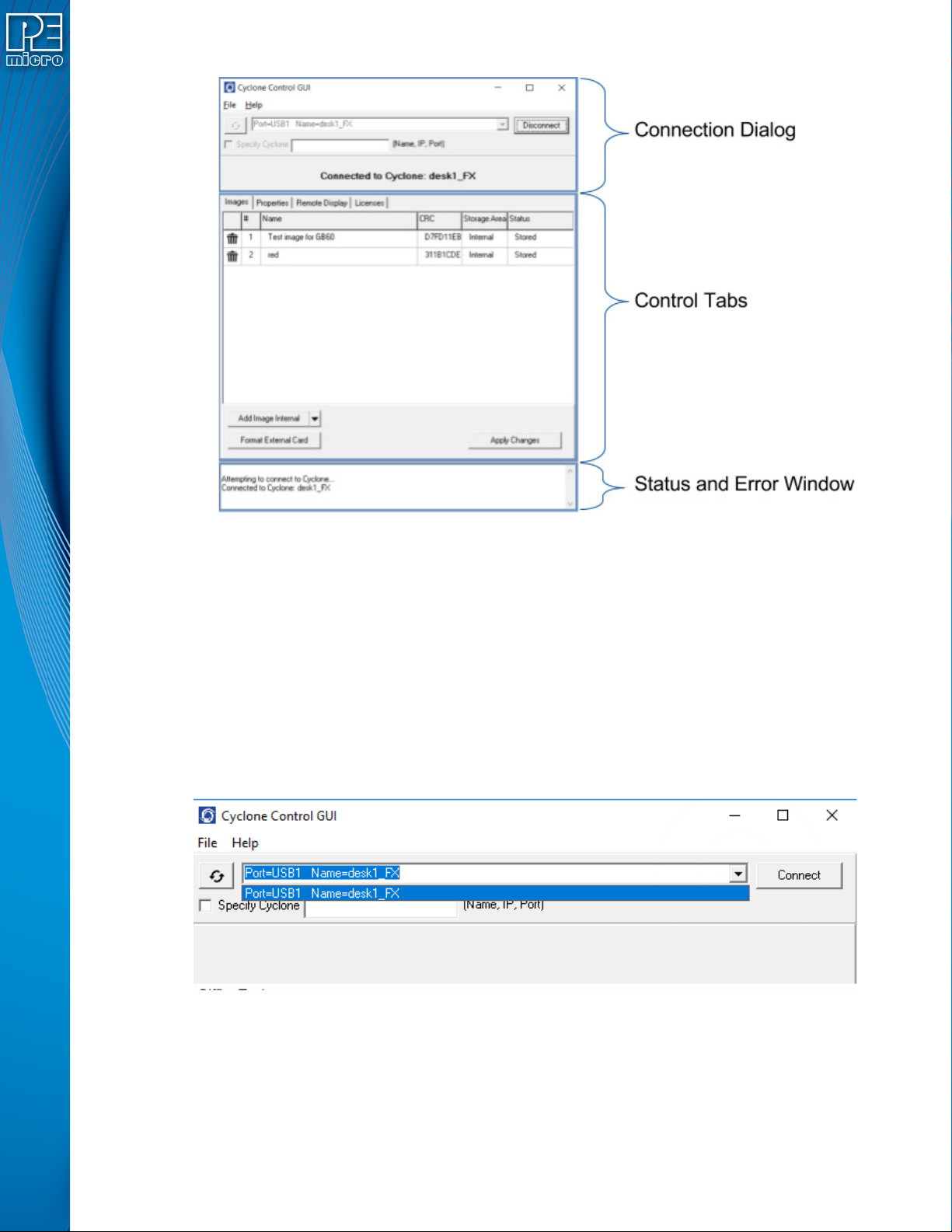
8.4.1 The Connection Dialog
Allows the user to specify a Cyclone to connect with, as well as specify the connection options.
The utility will always automatically upgrade the firmware of a Cyclone if the firmware in the
Cyclone is outdated. However, firmware update can also be forced by using the checkbox in File>Force Firmware Update. This option will update the firmware on the Cyclone with the latest
firmware in the same folder as the Cyclone Control GUI.
At launch, the Cyclone Control GUI will show all the Cyclones detected on the network and those
attached by USB connections in a drop-down list. Cyclones can also be connected to by using the
“Specify Cyclone” checkbox and specifying a Cyclone by identifier. This identifier can by the
Cyclone name, its IP address or its port number.
Figure 8-2: Areas of the Cyclone Control GUI
Figure 8-3: Select Cyclone From Drop Down
Once the Cyclone is selected, clicking on the “Connect” button will bring a series of tabs that will
allow full access to the Cyclone.
8.4.2 The Control Tabs:
The control tabs allow all access to the Cyclone. Through these tabs you can view, add, and erase
User Manual For CYCLONE FX Programmers 73
Page 79
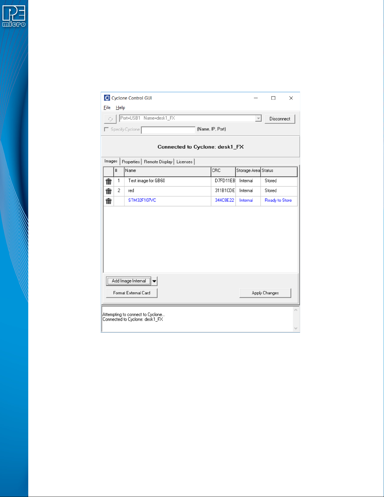
Cyclone images, you can view and modify properties, you can modify licenses and see the
Cyclone screen remotely.
8.4.2.1 The Images Tab
The Images tab allows to modify the Cyclone images both in internal Cyclone memory and in
external memory cards. To add a new image to the Cyclone, click on the “Add Image Internal”
button and selected the image you want to add. For the changes to take effect, the “Apply
Changes” button needs to be clicked, this will place the image in the Cyclone memory.
Figure 8-4: Images Tab
To store an image in the external memory of the Cyclone, change the storage area by clicking on
the drop down menu next to the “Add Image” button. Changing the storage area can also right click
on the uncommitted image and select the “Switch storage to External” option.
User Manual For CYCLONE FX Programmers 74
Page 80

Figure 8-5: Changing Storage Area
A blue image is not committed, disconnecting from the Cyclone before the “Apply Changes” button
is clicked will discard any changes not committed.
Erasing an image can be done by clicking on the trashcan icon at the left of the image, it can also
be done by selecting the image and click the DELETE key on the keyboard. The “Apply Changes”
buttons must be clicked for any changes to the Cyclone to take place.
To format the external memory card click on the “Format External Card” button. This will erase all
image information stored in the external card.
From this tab a user can also access the image properties of images in the Cyclone. Just right click
on the image then click on “View Image Properties” and a window with public image properties will
pop up.
Figure 8-6: Image Properties Window
Properties like the image name, the voltage settings, image CRC, and all current serial numbers
can be viewed from this window. Use this feature to make sure your image settings are correct or
check that the serial numbers change accordingly.
User Manual For CYCLONE FX Programmers 75
Page 81
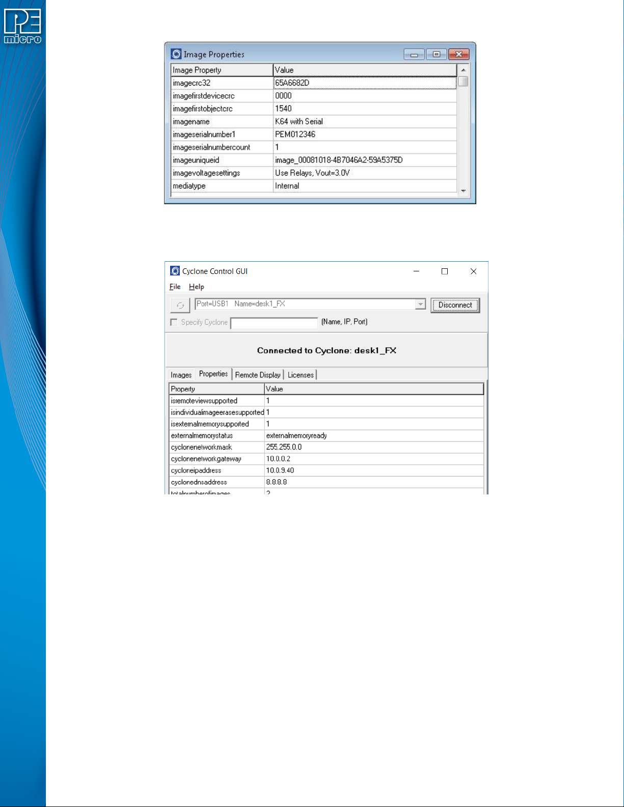
8.4.2.2 The Properties Tab
Figure 8-7: Example: Edit Image Serial Number
Figure 8-8: Properties Tab
The properties tab shows all the network, Cyclone and image properties. It also shows properties
for the supported features of the Cyclone. From this tab the Cyclone firmware and logic versions,
the cyclone type, and the number of images are available. Also from this tab some of the
properties can be modified.
Modifying a Cyclone property - Some properties in the Cyclone are modifiable. Only the properties
that can be modified will show three dots to the right of the property when the property is selected.
User Manual For CYCLONE FX Programmers 76
Page 82
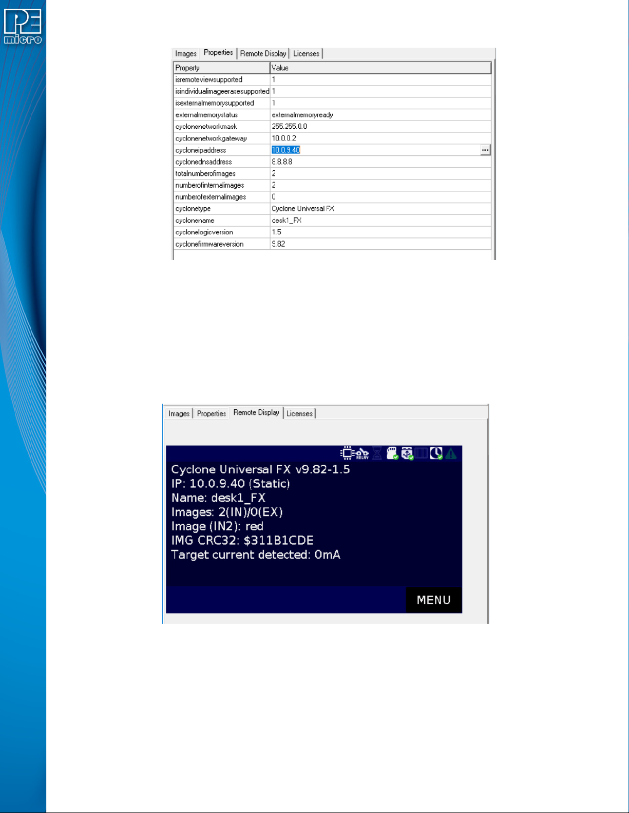
Clicking on the three dots or double clicking on the property value will bring up an edit window.
Write the new property value and click “OK”, the property window will refresh and the value
showed will be the updated value of the property.
8.4.2.3 The Remote Display Tab
This tab will show the current display of the Cyclone. The utility checks every second for changes
in the display and updates the image to the current display. This image is also clickable so clicks
on the virtual screen are also registered by the Cyclone.
Figure 8-9: Modifying Properties
Figure 8-10: Remote Display & Control of Cyclone Screen
8.4.2.4 The Licenses Tab
New licenses can be added to the Cyclone using the Licenses tab. Clicking on “Add New License”
will prompt the P&E License Activation Form. This form takes in the Installation Code for a product
and can automatically validate and register the installation.
This tab also shows the current Cyclone Control Suite licenses active in the Cyclone, including the
Cyclone Control Advanced Automation License and the Cyclone Memory Expansion License.
User Manual For CYCLONE FX Programmers 77
Page 83
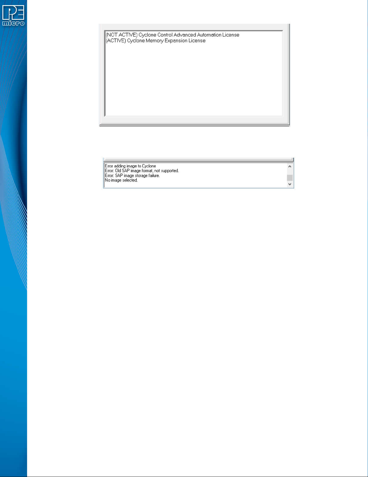
8.4.3 The Status and Error Window:
Figure 8-12: Status & Error Window
This section of the Cyclone Control GUI displays the status of the utility as well as any errors
during the connection or any of the actions performed by the utility. It’ll show detailed errors on
images that failed to be properly added or actions that require additional licensing.
This new status and error window increases the visibility of the user into the tasks the utility is
performing as well as the issues that may arise.
8.5 License
The Cyclone Control Suite software does not need a license to operate when using the standard
features with any touchscreen Cyclone or when using advanced features with a Cyclone FX. When
using the advanced automation features of the SDK or Console with non-FX cyclones, a “Cyclone
Control Advanced Automation License” needs to be present in the Cyclone. This advanced license
is available for purchase for the Cyclone Universal and Cyclone ACP programmer.
Advanced automation features in the Cyclone Control Suite are not available for non-touchscreen
cyclone models (Cyclone Max, Cyclone Pro, Cyclone ST, and Cyclone Renesas). Please use the
Classic Cyclone Automated Control Package when using advanced features with these Cyclones
Figure 8-11: Licenses Tab
8.5.1 Hardware Licensing
As part of the Cyclone Control Suite, PEmicro is instituting a new product licensing procedure that
is centered on the PEmicro hardware being used (such as a Cyclone or a USB Multilink), and not
on the traditional software-based seat-license. The new licensing mechanism provides customers
with a greater operational flexibility, particularly in a production environment where PEmicro's
hardware may not be directly connected to a licensed PC.
8.5.2 Advantages of a Hardware-Based License
A hardware-based license creates greater flexibility and new opportunities. For example, a
customer in Germany can configure a Cyclone for a contract manufacturer in China, without
requiring the contract manufacturer to re-license PEmicro's software. The manufacturer can simply
download any PEmicro software, and as long as a licensed PEmicro hardware is available on site,
they can simply use the product.
Additionally, a hardware license no longer requires a networked or USB connection to a host PC,
User Manual For CYCLONE FX Programmers 78
Page 84

thereby making possible stand-alone operations that may require licensing (such as the use of an
SDHC card). Moreover, hardware licensing simplifies the management of personal computers by
IT departments. PCs can be replaced, upgraded, or re-formatted, without any impact to the
functionality and /licensing in place on PEmicro's hardware.
One last very beneficial feature of the hardware licensing mechanism is the fact that it requires no
change to how licenses are obtained from PEmicro. It preserves backwards compatibility, and it
maintains the same traditional licensing workflow that was previously used to license PEmicro
software.
8.5.3 How to Obtain a Hardware License:
At the time of purchase of a product, the customer can simply choose between software or
hardware licenses (with the knowledge that new features will only be supported through hardware
licensing). The customer will receive an installation code as before, which they can then use to
register the product with PEmicro. Upon registration, the customer is provided with the product
Activation Code (license) that will automatically be saved on the connected hardware in the case
of a hardware license, or onto the PC in the case of a software license. Thereafter, the user’s
hardware-licensed PEmicro tools can be accessed and used from any PC.
User Manual For CYCLONE FX Programmers 79
Page 85

9 SAP IMAGE COMPILER (SCRIPTED PROGRAMMING & IMAGE
CREATION)
PEmicro’s Cyclone SAP Image Compiler, or CSAP, is an essential component in the Stand-Alone
Programming (SAP) image creation process. It is designed to work in tandem with the Cyclone
Image Creation Utility, by running in the background, but it can also be called directly by the user.
The CSAP image compiler typically takes the .CFG file that was generated by the Image Creation
Utility and uses it to locate and combine all of the components that will be included in the specific
SAP image that is being created. However the user can also use a command line to submit a CFG
file and various Command-Line Parameters directly to the image compiler. This allows users to
write scripts that can automate the image creation/re-creation process.
In order for the user to do this, they will need to know what Command-Line Parameters are
available and how they are used, and what items can/must be included in a CFG file, including
Programming Commands and Configuration Commands. There is also a specific Command-Line
Parameter that allows the user to easily substitute values inside a specific CFG file. This can
enable a single CFG file to be used to create different SAP images.
9.1 Launching From the Command Line
The image compiler can be launched from the command line to create a SAP image. Below is an
example of a command-line that the user might put together, along with descriptions of its various
components.
9.1.1 Command-Line Example
Below is an example of using the command line to launch CSAP for ARM Cortex devices. The
command line specifies where to locate the .CFG file and other necessary information.
>csapacmpz.exe "C:\MyWorkspace\MyProject\KL25Z128_script.cfg" /imagefile "C:\MyWorkspace\MyProject\KL25Z128_image.sap"
Most command-line parameters can be used with any device, but some are specific to certain
architectures or device types.
9.1.1.1 CSAP Executable
The user must first specify the particular CSAP executable that is compatible with their device. See
the area of the example in green, which is specifically for ARM devices:
>csapacmpz.exe "C:\MyWorkspace\MyProject\KL25Z128_script.cfg" /image-
file "C:\MyWorkspace\MyProject\KL25Z128_image.sap"
Below is a list of which executable corresponds to which architecture/device type.
Target Architecture / Executable Name
ARM-based devices (all manufacturers) : CSAPACMPZ.exe
MAC71XX, MAC72XX: CSAPARMZ.exe
HC(S)12(X): CSAPBDM12Z.exe
ColdFire V1: CSAPBDMCFV1Z.exe
ColdFire V2, V3, V4: CSAPBDMCFZ.exe
MPC5xx/8xx: CSAPBDMPPCZ.exe
DSC: CSAPDSCZ.exe
HCS08: CSAPHCS08Z.exe
User Manual For CYCLONE FX Programmers 80
Page 86

HC08: CSAPMON08Z.exe
MPC55XX-57XX: CSAPPPCNEXUSZ.exe
RS08: CSAPRS08Z.exe
S12Z: CSAPS12ZZ.exe
STM8: CSAPWIZ01.exe
9.1.2 Filename and Additional Command-Line Parameters
After specifying the executable, the user must also include the [filename] parameter, which
represents the path and filename of the .CFG file. This is shown in blue in the example below. The
user may also include one or more other command-line parameters. The area of the example in
violet shows these other command-line parameters.
>csapacmpz.exe "C:\MyWorkspace\MyProject\KL25Z128_script.cfg" /image-
file "C:\MyWorkspace\MyProject\KL25Z128_image.sap"
9.1.3 List of Valid Command-Line Parameters
Here is the listing of valid parameters:
[executable] Specifies the particular CSAP executable that is compatible with the user’s device.
Mandatory.
[filename] A configuration file containing configuration commands and comments,
default = PROG.CFG. Mandatory.
[?] Use the '?' character option to cause the utility to wait and display the result of
configuration in the image compiler window. If the user does not use a batch
file to test error level, this provides a method to display the configuration
result. This option should be the FIRST command-line option.
[hideapp] This will cause the CSAP executable programmer to NOT display a visual
presence while running, with the exception of appearing on the taskbar. (32bit applications only)
[/logfile logfilename] This option opens a logfile of the name "logfilename" which will cause any
information which is written to the status window to also be written to this file.
The "logfilename" should be a full path name such as c:\mydir\mysubdir\mylog.log.
Note: When using Windows, if the logfilename path or filename include any white
spaces then the logfilename path and filename must be surrounded by double quotation marks.
[/imagefile imagefilename]Used when the SAP file should be saved to disk instead of stored on the
Cyclone. This specifies the path and filename for the SAP file. A user may
later update a Cyclone with this image file.
Note: If the image path or filename include any white spaces then the image path
and filename must be surrounded by double quotation marks.
User Manual For CYCLONE FX Programmers 81
Page 87

[imagecontent] This command-line parameter is a string that can be used to describe the SAP
image, whether it is stored in a file or on the Cyclone. If the configuration command :DESCRIBEIMAGE is also present in the .CFG file, this will be overwritten.
[paramn=s] This is a type of command-line parameter that can be used within the .CFG
file as a placeholder for data, and this data can then be specified on the command-line. Multiple scripts can potentially reference the same .CFG file, each
specifying different data on the command-line.
The n is a numeral, which allows multiple parameters to be used within the
same .CFG file.
See Section 9.2.4 - Using Command Line Parameters Inside a .CFG File
for more information and examples.
9.2 Configuration (.CFG) File Contents
A Configuration (.CFG) file includes programming commands and the location of the binary files
and programming algorithm to be used during programming. It may also include configuration
commands and may refer to utilities that can augment the programming process, such as
serialization, or setup information for use of a bar code scanner during programming.
Because the CFG file is essential to the process of creating a SAP image, the command-line used
to call CSAP must always use the [filename] parameter to specify a .CFG file. This file will instruct
the image compiler which components will be used to create the eventual SAP image and where to
them, among other things.
9.2.1 Sample .CFG File
A .CFG file is a pure ASCII file that includes one command per line. It will always include two main
types of commands: Configuration Commands and Programming Commands. It can also include a
certain type of command-line parameter that can serve as a placeholder for some of the script
contents.
Below is a sample .CFG for NXP’s Kinetis KL25Z128 device. Lines in the file that begin with
semicolons are comment lines.
The first several lines are comments that describe some of the attributes of the programming
setup. The next several lines, which begin with a colon, are Configuration Commands that are read
before programming. The final several lines are the Programming Commands that will be executed
during the programming process.
; Automatically generated configuration file
; Silicon Manufacturer is NXP
; Silicon Architecture is ARM Based (Kinetis, LPC, etc.)
;
:ALLOWOUTOFRANGE 1
:DEVICE NXP_K7x_K70FN1M0M15
:USESWD 1
:DEBUGFREQUENCY 5560
:SAPGUIVERSION 352E3737
:PROVIDEPOWER
:POWERVOLTAGE 3.0
:POWERDOWNDELAY 250
:POWERUPDELAY 250
:KEEPPOWERON 0
:CUSTOMTRIMREF 31250.00
User Manual For CYCLONE FX Programmers 82
Page 88

:NEWIMAGE
:DESCRIBEIMAGE Test_K70
CM
C:\PEMicro\cyclone\supportfiles\supportFiles_ARM\NXP\K7x\freescale
_k70fn1m0m15_1x32x256k_pflash.arp
SS C:\test\nxp\armcortex\mk_x_32_pflash_dflash_m5_05A0_1FFF.s19
EN ;Erase if not Blank
PM ;Program Module
VC ;Verify Checksum
9.2.2 Configuration Commands
Configuration Commands are commands that will be executed at startup, before the programming
process. You can see configuration commands used inside a sample .CFG file above in Section
9.2.1 - Sample .CFG File. They listed are in the middle of the file. They always begin with a colon.
A listing of valid Configuration Commands and their formats is included below.
9.2.2.1 Target Power Related Configuration Commands
9.2.2.1.1 :PROVIDEPOWER n
Processors: All (EXCEPT MON08)
Determines whether the Cyclone should provide power to the target. (This is the same as legacy
option :USEPRORELAYS n).
Note: Not all hardware interfaces support this command. Valid values of n are:
0 : Cyclone does NOT provide power to target. (default)
1 : Enable Cyclone to provide power to target.
9.2.2.1.2 :POWERVOLTAGE n.n
Processors: All
Use this command if the Cyclone is providing/switching power to the target, otherwise omit this
command. Specifies the target voltage as a real number. Acceptable range is from 1.6V - 5.0V.
:POWERVOLTAGE 3.3 Specifies target voltage as 3.3V
9.2.2.1.3 :KEEPPOWERON n
Processors: All
Determines whether power provided to the target should be turned off when the application
terminates. NOTE: Not all hardware interfaces support this command. Valid values of n are:
0 : Turn power off upon exit (default)
1 : Keep power on upon exit
9.2.2.1.4 :POWERDOWNDELAY n
Processors: All
Amount of time to delay when the power to the target is turned off for the target’s power supply to
drop to below 0.1v. n is the time in milliseconds.
9.2.2.1.5 :POWERUPDELAY n
Processors: All
Amount of time to delay when the power to the target is turned on OR the target is reset, and
before the software attempts to talk to the target. This time can be a combination of power on time
and reset time (especially if a reset driver is used). n is the time in milliseconds.
User Manual For CYCLONE FX Programmers 83
Page 89

9.2.2.2 Trim Related (If supported) Configuration Commands
9.2.2.2.1 :CUSTOMTRIMREF n.nn
Processors: All
Desired internal reference clock frequency for the “PT; Program Trim” command. This frequency
overrides the default internal reference clock frequency. Valid values for “n.nn” depend on the
particular device being programmed. Please refer to the electrical specifications of your device for
valid internal reference frequency clock range.
Where:
n.nn : Frequency in Hertz with two decimal places
9.2.2.3 Information Processing Configuration Commands
9.2.2.3.1 :CLEARSTATUS n
Processors: All
Specifies the amount of time after programming, in milliseconds, before the Success indicator
(LED) will be turned off.
9.2.2.3.2 :DESCRIBEIMAGE string
Processors: All
string This is a string that describes the SAP image. Will overwrite the command-line parameter
“imagecontent” if both are present in the .CFG file.
Example:
:DESCRIBEIMAGE KL25Z128 TEST IMAGE
9.2.2.3.3 :ALLOWOUTOFRANGE n
Processors: All
Sets whether programming will continue when data is out of range.
:ALLOWOUTOFRANGE 1 Allows programming to continue when some data is out of
range (addresses not in module). Out of range data is
ignored.
:ALLOWOUTOFRANGE 0 Requires all programming data to be in range of the module.
Out of range data causes an error on image creation.
9.2.2.4 Image Security Configuration Commands
9.2.2.4.1 :PROGRAMLIMIT n
Processors: All
Sets a limit to the number of devices that the Cyclone may program, until this limit is removed or
reset.
9.2.2.4.2 :DATERANGE mm/dd/yyyy mm/dd/yyyy
Processors: All
Sets a starting date and ending date for Cyclone programming operations. The Cyclone will then
only allow devices to be programmed on or between these two dates, until the date limit is
removed or reset. Dates always refer to the Cyclone’s internal calendar. The character between
the two dates should be a single space. The dates should be listed in chronological order, first to
last.
Example:
:DATERANGE 05/10/2018 05/12/2018 Allows Cyclone programming operations on
User Manual For CYCLONE FX Programmers 84
Page 90

5/10/2018, 5/11/2018, and 5/12/2018. Does not
allow it on any other dates.
9.2.2.4.3 :ERRORLIMIT n
Processors: All
Sets a limit to the number of errors that may occur while the Cyclone is programming devices.
Once this limit has been reached, the Cyclone will no longer program devices until the error limit is
removed or reset.
9.2.2.5 Image Launch Settings Configuration Commands
9.2.2.5.1 :BARFILE barfile
Processors: All
Specifies that a .BAR file will be used during programming (programming initiated by bar code
scanner).
barfile Indicates the path and filename of the .bar file.
Example:
:BARFILE C:\PEMicro\cyclone\imageCreation\barcodeTest.bar
9.2.2.6 Connection Related Configuration Commands (ARM)
9.2.2.6.1 :DEVICE string
Processors: ARM, DSC, MAC7xxx
For ARM devices, this is a mandatory parameter that specifies the device. It is required because
the debug protocol changes between manufacturers and sometimes also between families or
devices.
Where:
string: represents the device and follows the “VENDOR_FAMILY_DEVICE” format.
For ARM devices, the easiest way to obtain the device string is from the Device Selection dialog
in the Cyclone Image Configuration Utility software. In the PEMICRO Connection Manager, click
“Select New Device” to open the Device Selection dialog. Expand the device tree to find your
device, then right-click and select “Copy Device String to Clipboard.”
9.2.2.6.2 :DEBUGFREQUENCY n
Processors: ARM, ColdFire, PPC, MAC7xxx
Specifies the communications frequency with the target device.
n Frequency in Kilohertz.
9.2.2.6.3 :USESWD n
Processors: ARM, MAC7xxx
Allows the user to specify SWD (single wire debug) mode instead of JTAG mode.
0 Specifies that JTAG mode will be used during communications (default).
1 Specifies that SWD (single wire debug) mode will be used during communications.
9.2.2.6.4 :JTAGTAPNUM n
Processors: ARM, MAC7xxx
The JTAG Tap Number is the index of the target device in the daisy chain. The first device
connected to TDI is index 0, the next is index 1, and so on. The index of the last device connected
to the TDO of the debugger is the total number of devices in the chain minus 1.
Note: This command is mandatory for JTAG daisy chain configurations. It is also important to specify
User Manual For CYCLONE FX Programmers 85
Page 91

JTAG communications using the :USESWD 0 command/value.
n Specifies the index number of a device in the daisy chain.
For more information on how to program or debug with a daisy chain setup, read:
http://www.pemicro.com/blog/index.cfm?post_id=136
9.2.2.6.5 :JTAGPREIR n
Processors: ARM, MAC7xxx
Every JTAG device has an IR register that is a certain width in bits. In the daisy chain the number
of Pre-IR bits is the sum of all of the IR registers between your device and the TDO pin.
Note: This command is mandatory for JTAG daisy chain configurations. It is also important to specify
JTAG communications using the :USESWD 0 command/value.
n Specifies the total length of IR registers following the target device. The first device in
the daisy chain is index 0.
For more information on how to program or debug with a daisy chain setup, read:
http://www.pemicro.com/blog/index.cfm?post_id=136
9.2.2.6.6 :RSTLOWPOSTSAP
Processors: All
Drives the RESET signal LOW before and after SAP operations.
9.2.2.7 Connection Related (S08, S12, ColdFire V1, RS08, S12Z) Configuration Commands
9.2.2.7.1 :DRIVEBKGDLOW n
Processors: S08, S12, CFV1, S12Z Note: Not RS08.
By default, the BKGD signal is driven low before and after programming operations are complete.
0 Do NOT drive BGND low before and after programming operations.
non-zero or missing Drive BGND signal low before and after programming operations.
Example:
:DRIVEBKGDLOW 0 Does NOT drive the BKGD signal LOW after operations are complete.
9.2.2.7.2 :RSTLOWPOSTSAP
Processors: All
Drives the RESET signal LOW before and after SAP operations.
9.2.2.8 Connection Related Configuration Commands (ColdFire V2, V3, V4)
9.2.2.8.1 :USEPSTSIGNALS n
Processors: ColdFire
Specifies whether to use PST signals during debug.
0 Do not use PST signals.
1 Use PST signals.
9.2.2.8.2 :RSTLOWPOSTSAP
Processors: All
Drives the RESET signal LOW before and after SAP operations.
User Manual For CYCLONE FX Programmers 86
Page 92

9.2.2.9 Connection Related (MPC5xxx, SPC5xxx) Processors
9.2.2.9.1 :DEBUGFREQUENCY n
Processors: ARM, ColdFire, PPC, MAC7xxx, DSC, PPCNexus
Specifies the communications frequency with the target device.
n Frequency in Kilohertz.
9.2.2.9.2 :UNCENSOR n
Processors: PPCNexus
This parameter should be used if 64-bit and 256-bit censorship passwords are needed to bypass
security.
Note: The ASCII version of the password must have each long word separated by a dash.
n Password represented as a hexadecimal value, with no symbols or spaces
9.2.2.9.3 :RSTLOWPOSTSAP
Processors: All
Drives the RESET signal LOW before and after SAP operations.
9.2.2.10 Connection Related - DSC Processors
9.2.2.10.1 :DEVICE string
Processors: ARM, DSC, MAC7xxx
Describes the device being programmed.
string Describes the device being programmed.
9.2.2.10.2 :RSTLOWPOSTSAP
Processors: DSC, STM8
Drives the RESET signal LOW before and after SAP operations.
9.2.2.11 Connection Related - MON08 Processors
When using MON08 devices, the user must specify :POWERVOLTAGE and :POWERUPDELAY &
:POWERDOWNDELAY.
9.2.2.11.1 :DEVICECLOCK n
For Class 5, 6, 7, and 8 devices. Controls whether the Cyclone should drive a clock to the target or
whether the PEmicro interface should tristate its clock output. Valid values of n are:
0 : Clock driven by Cyclone. Must use :OUTPUTCLOCK to specify.
1 : Target self-clocked, Cyclone clock output disabled
9.2.2.11.2 :OUTPUTCLOCK n
Specifies the clock when :DEVICECLOCK is set to 0 (driven by Cyclone). Valid values of n are:
0 : 4.9152 MHz
1 : 9.8304 MHz
9.2.2.11.3 :CLOCKDIVIDER n
For Class 5, 6, 7, and 8 devices. Often one of the port pins of the target processor controls the
ratio of the BUS clock to the External clock. Valid values of n are:
0 : Divide by 2 (usually and if applicable)
User Manual For CYCLONE FX Programmers 87
Page 93

1 : Divide by 4 (usually and if applicable)
9.2.2.11.4 :BAUD n
Sets the baud rate to n. Serial port connection only If :BAUD is specified, include :FORCEPASS
followed by :SECURITYCODE.
9.2.2.11.5 :FORCEPASS
Specifies that security should be passed on startup of the software instead of waiting for an EM
(Erase Module) command. The :SECURITY code command must also be provided.
9.2.2.11.6 :SECURITYCODE hh hh hh hh hh hh hh hh
Specifies the 8 bytes of security code to use at startup which correspond to the addresses $FFF6$FFFD of the target HC08 device. The parameter for this is a string containing 8 bytes of data in
HEX separated by white spaces.
9.2.2.11.7 :DEVICETYPE string
Specifies the target device family. As an example, the device type for a 68HC908KX8 would be
KX. The allowed device type values are:
AB,AP,AS,AT,AZ,BD,EY,GP,GR,GR4/8,GT,GZ,JB12,JB16, JB1/8,JG,JK,JL,JR,JW,KX,LB,LD,
LJ,LK,LT,LV,MR4/8,MR16/32,QB,QC,QL,QT,QY,RF,RK,SR
9.2.2.12 Connection Related - STMicroelectronics’ STM8 Processors
9.2.2.12.1 :ARCHTYPE n
Processors: STM8
Specifies the STM8 family via the numeral n, where n indicates the following:
161 = STM8S/STM8A
162 = STM8L101X
163 = STM8L15X
164 = STM8L16X
9.2.2.12.2 :COMMSMODE 0
Processors: STM8
Indicates that communications speed should be controlled automatically.
9.2.2.12.3 :FORCEPASS
Processors: STM8
If this command is present, read-out protection will be ignored, i.e. the target will be unsecured and
the programming process will continue.
If this command is missing, read-out protection will NOT be ignored. If the device is protected the
programming process will not proceed.
9.2.2.12.4 :RSTLOWPOSTSAP
Processors: All
Drives the RESET signal LOW before and after SAP operations.
9.2.3 Programming Commands
Programming Commands are the commands that will be executed during the programming
process. These are the main commands that will manipulate and verify data on your device. A list
of programming commands and their formats is included below.
See Section 9.2.1 - Sample .CFG File to view programming commands within a CFG file. The
User Manual For CYCLONE FX Programmers 88
Page 94

example programming commands are at the bottom of the file.
Note: The command parameter formats starting_addr, ending_addr, base_addr, and byte, word are
hexadecimal by default.
BM Blank check module.
BR starting_addr ending_addr Blank check range.
CM Choose module (algorithm) file. Note: Certain modules may require a base address to be
specified
EB starting_addr ending_addr Erase byte range.
EW starting_addr ending_addr Erase word range.
EM Erase module.
EN Blank check and erase
GO Starts device running. Can be used as final command if you want the device to run for
testing. Should be immediately preceded by an 'RE' command.
PB starting_addr byte ... byte Program bytes.
PF feature_ID starting_addr Program feature data. feature_ID must be: datestr, datetimestr,
barcodestr, or runtestdata. See Section 6.1.3.9 - Program
Feature Data.
PW starting_addr word ... word Program words.
PM Program module.
PT Program trim (devices with trim only)
RE Reset chip.
SS path Specify binary data file (S19/Elf/Hex) Path indicates file path to the binary.
VC Verify the programmed device using a checksum
VM starting_addr ending_addr Verify module.
VR starting_addr ending_addr Verify range.
VV type Verify module CRC. Type is CRC8 or CRC16.
DE timeinms - Delays "timeinms" milliseconds
9.2.4 Using Command Line Parameters Inside a .CFG File
The user may wish to make their .CFG files more versatile by inserting one or more placeholders
into the script, and then specifying the values for those placeholders later, on the command line,
when calling the CSAP executable that will references that script.
The command-line parameter /PARAMn=s can be used to insert text into a .CFG file. It can
replace any part of the script including programming commands, filenames, and parameters. n is a
numeral from 0..9, which allows you to use multiple versions of this command line parameter in a
.CFG file. s represents a string which will replace any occurrence of /PARAMn in the script file.
As an example, the following section of a .CFG script features three instances of /PARAMn=s: /
PARAM1, /PARAM2, and /PARAM3:
RE ;Reset the MCU
CM /PARAM1 ;Choose Flash Module
EM ;Erase the module
BM ;Blank Check the module
SS /PARAM2 ;Specify the S19 to use
PM ;Program the module with the S19
/PARAM3 ;Verify the module again
User Manual For CYCLONE FX Programmers 89
Page 95

When the user calls the CSAP executable that will reference this CFG file they will need to specify
the values of these parameters on the command line. See the example below, where the first of
these parameters is used to specify a programming algorithm (.SRP), the second an .S19 file, and
the third a programming command (VM).
CSAPACMPZ
/PARAM1=C:\PEMICRO\Freescale_MK40X256_PFlash_DFlash.ARP
“/PARAM2=C:\PEMICRO\EXAMPLE FILES\TEST.S19"
/PARAM3=VM
Note: Notice that /PARAM2 is enclosed in double quotation marks. This is because the parameter has a
space in its value (Example Files). The surrounding double quotation marks are required in this
situation, in order to indicate to Windows that it is a single parameter.
The complete example command line would be as below (note that this is one continuous line; no
line breaks):
C:\PROJECT\CSAPACMPZ C:\PROJECT\GENERIC.CFG /
PARAM1=C:\PEMICRO\Freescale_MK40X256_PFlash_DFlash.ARP “/
PARAM2=C:\PEMICRO\EXAMPLE FILES\TEST.S19” /PARAM3=VM
9.2.5 Sample Batch File
Here is an example of how to call a command-line programmer and test its error code return in a
simple batch file. Sample batch files are given for both Windows 95/98/XP and Windows 2000/NT/
XP/Vista/7/8/10.
9.2.5.1 Windows NT/2000/Vista/7/8/10:
C:\PEMicro\CYCLONE\IMAGECREATION\IMAGECREATIONSUPPORTFILES\CSA
PACMPZ.EXE C:\PROJECT\ENGINE.CFG
PORT=USB1
if errorlevel 1 goto bad
goto good
:bad
ECHO BAD BAD BAD BAD BAD BAD BAD BAD
:good
ECHO done
Note: Path names of files that are relative to the CSAP executable can also be used.
9.3 CSAP Error Returns
An Error code is returned by the Image Compiler so that a script file or an application launching the
Image Compiler can check for it. The error codes used are:
0 - Program completed with no errors.
1 - Canceled by user.
2 - Error reading S record file.
3 - Verify error.
4 - Verify canceled by user.
5 - S record file is not selected.
User Manual For CYCLONE FX Programmers 90
Page 96

6 - Starting address is not in module.
7 - Ending address is not in module or is less than starting address.
8 - Unable to open file for uploading.
9 - File write error during upload.
10 - Upload canceled by user.
11 - Error opening algorithm file.
12 - Error reading algorithm file.
13 - Device did not initialize.
14 - Error loading .PCP file.
15 - Error enabling module just selected.
16 - Specified S record file not found.
17 - Insufficient buffer space specified by .PCP to hold a file S-record.
18 - Error during programming.
19 - Start address does not point into module.
20 - Error during last byte programming.
21 - Programming address no longer in module.
22 - Start address is not on an aligned word boundary.
23 - Error during last word programming.
24 - Module could not be erased.
25 - Module word not erased.
26 - Selected algorithm file does not implement byte checking.
27 - Module byte not erased.
28 - Word erase starting address must be even.
29 - Word erase ending address must be even.
30 - User parameter is not in the range.
31 - Error during algorithm-specified function.
32 - Specified port is not available or error opening port.
33 - Command is inactive for this .PCP file.
34 - Cannot enter background mode. Check connections.
35 - Not able to access processor. Try a software reset.
36 - Invalid algorithm file.
37 - Not able to access processor RAM. Try a software reset.
38 - Initialization cancelled by user.
39 - Error converting hexadecimal command number.
40 - Configuration file not specified and file prog.cfg does not exist.
41 - Algorithm file does not exist.
42 - Error in io_delay number on command line.
43 - Invalid command line parameter.
44 - Error specifying decimal delay in milliseconds.
47 - Error in script file.
49 - Cable not detected
50 - S-Record file does not contain valid data.
51 - Checksum Verification failure - S-record data does not match MCU memory.
52 - Sorting must be enabled to verify flash checksum.
User Manual For CYCLONE FX Programmers 91
Page 97

53 - S-Records not all in range of module. (see "v" command line parameter)
54 - Error detected in settings on command line for port/interface
60 - Error calculating device CRC value
61 - Error - Device CRC does not match value given
70 - Error - CSAP is already running
71 - Error - Must specify both the INTERFACE and PORT on the command line
72 – The selected target processor is not supported by the current hardware interface.
User Manual For CYCLONE FX Programmers 92
Page 98

10 ETHERNET CONFIGURATION
This section describes the mechanism used by the Cyclone device to transact data over an
Ethernet network. It primarily focuses on the User Datagram Protocol (UDP), which is a popular
method for sending data over a network when the speed of a data transaction is of more concern
than the guarantee of its delivery. The Cyclone takes advantage of the UDP protocol’s penchant
for speed, and adds an extra layer of logic to guarantee the delivery of UDP packets in order to
offer a best-of-both-worlds solution.
10.1 Network Architectures
Before delving into the innards of Ethernet message passing, it is prudent to briefly describe the
different network architectures in use today, and how they pertain to the operation of the Cyclone.
Computers are, of course, connected to one another through intermediary devices in order to form
networks. There are several classes of these intermediary devices, but they generally fall into one
of the following three groups:
Hubs
At the most basic level, computers are connected to one another through a Hub. A Hub is
a device with several ports that are used to connect multiple computers together. It is a
repeater device – a Hub simply copies the data incoming on one port as data outgoing on
the other ports. In this manner, if there are four computers connected through a Hub, and if
the first computer is sending data to the second computer, then the third and the fourth
computers will also receive an identical copy of that data. Hubs are usually used to set up
a small Local Area Network (LAN), which may have on the order of 10 to 20 computers.
Switches
The aforementioned type of process, where the data is simply replicated onto every
available port, quickly becomes inefficient for larger sized networks. For this reason, a
larger sized LAN employs the usage of Switches instead of Hubs. A Switch is essentially a
smart Hub, in that it limits the input and output of data to the two transacting computers.
Routers
Larger networks, such as Wide Area Networks (WANs), or the Internet for that matter, use
progressively more sophisticated devices to transact data. At the core of these devices is
the Router, which functions as a switch between networks.
The Cyclone performs irrespective of the connection mechanism, with one very important caveat:
it needs to be set up with the appropriate network parameters for the underlying network
architecture.
10.2 Network Parameters
A typical network becomes operational not after the physical connections have been established,
but after network parameters in the form of IP (Internet Protocol) numbers have been assigned to
the individual computers. An IP number is a unique string that consists of four numbers ranging
between 0 and 255, separated by dots, e.g., 192.168.1.2. Every computer that is on a network
needs to have a unique IP number. The computer uses this IP number to identify itself on the
network, and also to address the recipient of its data.
Assignation of this IP number is sufficient information to transact data on a simple network
connected by a hub. On a more complex network, however, routing information becomes
important. The routing information consists of two more IP numbers. The first of these is called the
Subnet Mask, and is used to determine whether or not the destination address resides on the
same subnet (i.e., doesn’t need to be forwarded to another network). The other IP number is the
Gateway Address, which is the address of the computer that handles forwarding and receiving of
packets to and from other networks.
Before first use, the Cyclone needs to be programmed with a unique IP number, the Subnet Mask
IP number, and also the default Gateway’s IP number. This can be done via the USB or the Serial
port, and is described in greater detail in the “Configuring the Cyclone” section of this manual.
User Manual For CYCLONE FX Programmers 93
Page 99

10.3 Internet Protocol
Once the network has been established, and the IP numbers have been assigned, data can be
transacted over a network with one of several protocols. By far the most prevalent protocol is the
Transmission Control Protocol (TCP), which runs on top of the Internet Protocol in what is
collectively known as the TCP/IP protocol. The TCP/IP protocol was developed by the Department
of Defense to connect different computers from different vendors by a “network of networks,” which
has become what is known as the Internet today.
The primary purpose of the TCP/IP protocol was to prevent a complete network outage in the case
of a nuclear attack, by automatically rerouting data traffic through the functioning part of the
network. As such, the TCP/IP mechanism guaranteed delivery of data packets by introducing a
system of acknowledgments and sequence numbers for the data packets. This mechanism, while
good for transacting large amounts of data (such as email or file transfers), is unsuitable in the
real-time type environment in which the Cyclone operates. Because the Cyclone needs to transact
data as quickly as possible to the target, it takes advantage of TCP/IP’s alternative, the UDP/IP
protocol.
Unlike TCP/IP, the UDP/IP protocol is a connectionless, single-packet protocol that sends short
data packets at the expense of not guaranteeing their delivery. This makes the UDP/IP protocol
efficient in real-time applications such as broadcasting video over the Internet, where the
occasional loss of a frame of data is not going to hamper the overall viewing experience. Left
unmodified, the UDP/IP, with its lack of guarantees for packet delivery, would be unusable in an
environment where the delivery of a single byte of data needs to be guaranteed. The Cyclone
firmware adds mechanisms to the UDP/IP protocol, without affecting its underlying efficiency, to
guarantee delivery of data packets.
10.4 Connecting The Cyclone Device
There are two methods for establishing a connection between a Cyclone and a PC with an
Ethernet cable. The most basic method is to connect the Cyclone directly to a PC, via a cross-over
Ethernet cable. However, the more common method is to place the Cyclone and the PC on the
same network through a Hub.
10.4.1 Connecting the Cyclone to the PC over a network
The Cyclone was intended for use on a network of multiple computers (and other Cyclones). There
are many possible network configurations, and to describe them all is beyond the scope of this
document. However, most configurations are a modification of a basic theme, which is that of
connecting one or more PCs through a Hub to one or more Cyclones.
In order to connect these devices to the Hub, you will need to use the provided straight-through
Ethernet cable. The straight-through cable, which is the “standard” Ethernet cable, is used to
connect devices of different types together, such as a PC to a Hub, or a Hub to a Cyclone.
At this point it once again becomes necessary to program the Cyclone with valid IP numbers, the
process for which is described in greater detail in the following section. However, it is important for
the Cyclone and the PCs to have matching Subnet and Gateway IP numbers, and for each to have
a unique IP number on the network. An example of a setting for above is as follows:
IP Number Gateway IP Subnet Mask
PC1 192.168.100.1 192.168.100.3 255.255.255.0
PC2 192.168.100.2 192.168.100.3 255.255.255.0
CYCLONE 192.168.100.4 192.168.100.3 255.255.255.0
Gateway 192.168.100.3 192.168.100.3 255.255.255.0
It is important to briefly touch upon the underlying network architecture, which can be a 10Mb
(Megabit), 100Mb, 10/100Mb, half-duplex, or a full-duplex connection. The details of the underlying
network architecture are beyond the scope of this document, but it is sufficient to note that most
modern network cards, as well as the Cyclone device, have the capability to configure themselves
for the underlying network through the Auto-negotiation mechanism. Auto-negotiation is performed
as soon as a network cable is connected to the device, and it sets the operating parameters of the
User Manual For CYCLONE FX Programmers 94
Page 100

device to match those of the network.
10.4.2 Connecting Cyclone-to-PC via an Ethernet cable
In order to connect the Cyclone to a PC directly via an Ethernet cable, you need to use what is
known as a cross-over cable. A cross-over cable, which is not provided by PEmicro, is normally
used to connect two similar devices such as a PC to a PC, or a Hub to a Hub. It is a cable that has
its receive and transmit wires crossed over so that the similar devices can effectively communicate
with one another.
With this configuration, it is still important to assign IP numbers to both the PC and the Cyclone
device. Although at first glance it may not seem necessary to assign a Gateway address in this
configuration, the Cyclone was designed to operate on a network of more than two computers, and
therefore it needs to be programmed with a Gateway address.
Assuming the desktop’s IP number to be 192.168.100.1, this is an example of the three IP
numbers that would need to be programmed into the Cyclone:
IP Number Gateway IP Subnet Mask
PC 192.168.100.1 none 255.255.255.0
CYCLONE 192.168.100.2 192.168.100.1 255.255.255.0
For more information on programming these IP numbers into the Cyclone device, please see the
following section.
10.5 Cyclone IP Setup Via LCD Menu
When the user is connecting the Cyclone via Ethernet, before the connection is established
between the Cyclone and the network the menu’s Home Screen will display the Cyclone’s IP
address as 0.0.0.0.
Once a connection has been established, the menu’s Home Screen displays the Cyclone’s IP
address and connection setting (Static or Dynamic).
The Ethernet cable can either be attached at the start of Cyclone startup or connected after setup
is complete. The connection with the network will be established when the cable is connected. If
the Ethernet cable is disconnected after setup is complete, the user should be able to simply
reconnect the cable to reestablish networking. However, depending on the setup of the DHCP
server, if the Ethernet cable is left unplugged for a considerable time the IP address may expire
and connection will have to be set up once again. This can be accomplished by restarting the
Cyclone.
10.5.1 Configure Network Settings
To configure network settings for the Cyclone, navigate to the following Menu location:
Main Menu / Configure Cyclone Settings / Configure Network Settings
The following options will be available under Configure Network Settings:
• Show Current IP Settings
• Edit Static IP Settings
• Enable/Disable Dynamic IP
• Edit Cyclone Name
10.5.1.1 Show Current IP Settings
Show Current IP Settings displays the current IP settings, including:
• Current IP Mode
• IP Number
• Mask
• Gateway
User Manual For CYCLONE FX Programmers 95
 Loading...