

Page 1
Document Number: PD196-145R3
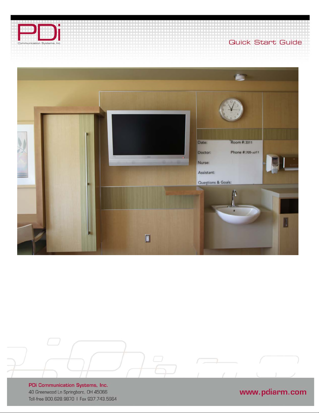
PDI-P26LCD, PDI-P32LCD
PDI-P40LCD
Healthcare-grade Televisions
Page 2
MODEL NUMBER:
PDI-P26/ P32/ P40 LCD
Document Number:
Page 1 of 9
an elevated position.
Better Solutions Are Within Reach
NOTE TO CABLE TV INSTALLER
This reminder is provided to call the cable TV systems installer’s
attention to Article 820-40 of the National Electrical Code. The
code provides guidelines for proper grounding and, in particular,
specifies that the cable ground shall be connected to the
grounding system of the building, as close to the point of the
cable entry as practical.
FCC
This equipment has been tested and found to comply with the
limits for a Class B digital device, pursuant to part 15 of the FCC
Rules. These limits are designed to provide reasonable
protection against harmful interference when the equipment is
operated in a residential or commercial installation. If this
equipment does cause harmful interference to radio or TV
reception, which can be determined by turning the equipment off
and on, the user is encouraged to try to correct the interference
by one of more of the following measures:
Reorient or relocate the receiving antenna.
Increase the separation between the equipment and
receiver.
Connect the equipment into an outlet on a circuit different
from that to which the receiver is connected.
Consult the dealer or an experienced radio/TV technician
for help.
TM
WARNINGS
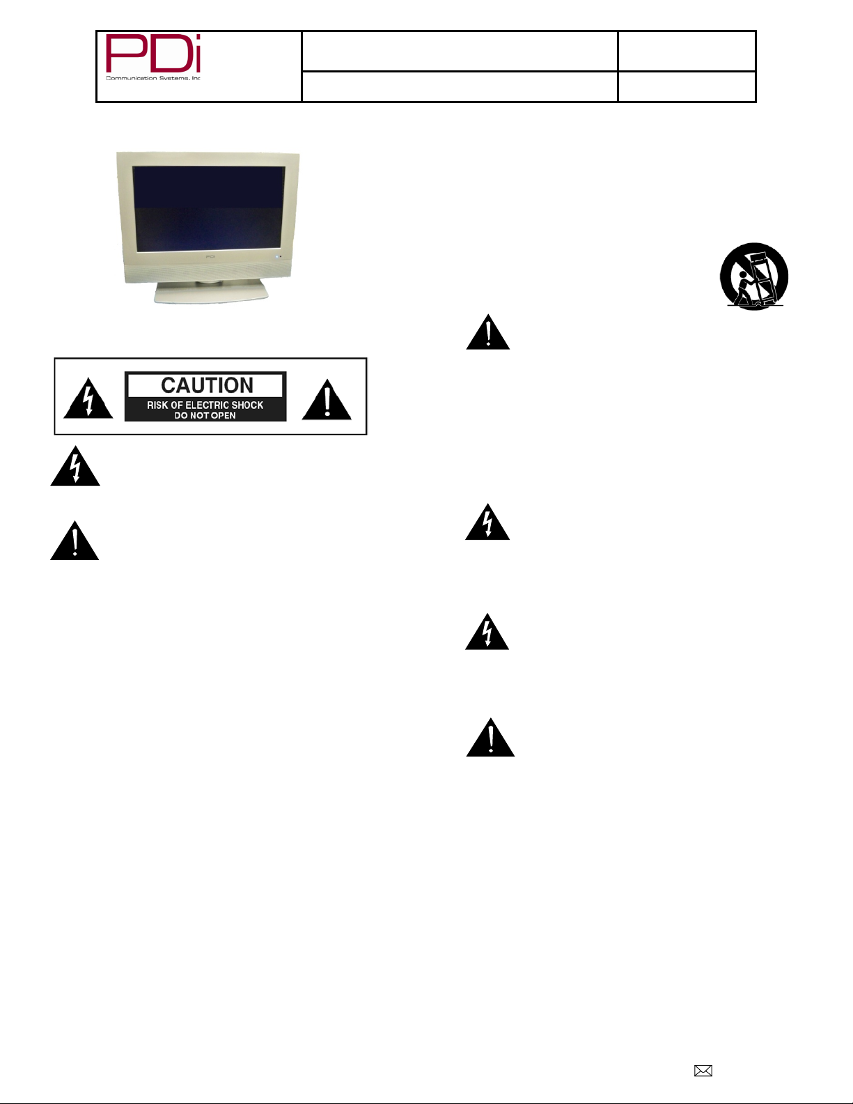
This symbol is intended to alert the user of the
presence of un-insulated ‘dangerous voltage’ within
the product’s enclosure that may be of sufficient
magnitude to constitute a risk of electric shock to
persons.
This symbol is intended to alert the user of the
presence of important operating and maintenance
(servicing) instructions in the literature
accompanying the appliance.
PD196-145R3
Quick Start Guide
SAFETY INSTRUCTIONS
INSTRUCTIONS
Be sure to read, follow, and keep these instructions. Heed all
the warnings.
OTHER EQUIPMENT
Use only with the cart, stand, tripod, bracket or
table specified by the manufacturer or sold with
the apparatus. Use caution when moving the
cart / apparatus combination to avoid injury from
tip-over.
MAINTENANCE AND SERVICING
Servicing is required when the apparatus has been
damaged in any way: the power cord or plug is
damaged, liquid has been spilled, objects have fallen into the
apparatus, the apparatus has been exposed to rain or moisture,
it does not operate normally, or it has been dropped.
Never remove the back cover of the TV; this can expose you to
high voltage and other hazards. If the TV does not operate
properly, unplug it and call an authorized service center or PDI.
POWER CORD
Protect the power cord from being walked on or pinched
particularly at the plugs, convenience receptacl es, and the point
where it exits from the apparatus.
CAUTION: DO NOT defeat the safety purpose of the
polarized or grounding-type plug. A pol ari zed
plug has two blades with one wider than the
other. A grounding typ e pl ug h as t wo pl at es a nd a t hi rd
grounding prong. The wide blade or the third prong is
provided for your safety. If the provided plug does not fit
into you r outl et, c ons ult a n elect ric ian for replac em ent of the
obsolete outlet.
RAIN AND MOISTURE WARNING: To avoid the
hazards of fire or electrical shock, DO NOT expose
this TV to rain or moisture.
WET LOCATION
The apparatus SHOULD NOT be exposed to dripping or
splashing. Objects filled with liquids, such as vases, SHOULD
NOT be placed on the apparatus.
OXYGEN ENVIRONMENT WARNING: DO NOT
use in an oxygen tent or an oxygen chamber. Such
use may cause a fire hazard.
CLEANING AND DISINFECTION
Clean the exterior of this TV by removing dust with a lint-free
cloth.
CAUTION: To avoid damage to the surface of the TV, DO NOT
use abrasive or chemical cleaning agents. Clean only with a dry
cloth.
DISCONNECTING DEVICE FROM MAINS
The main plug is the disconnecting device.
CAUTION: Unplug this apparatus during lightning storms or
when unused for long periods of time.
PRODUCT MODIFICATION
DO NOT attempt to modify this product in any way without
written authorization. Unauthorized modification could void the
user’s authority to operate this product.
OVERHEAD FALLING HAZARD
WARNING: To prevent injury, this apparatus must be securely
attached to the wall in accordance with the installation
instructions. TVs can pose a striking hazard when mounted at
PDi Communication Systems, Inc. 40 Greenwood Lane Springboro, Ohio 45066 USA PH 1-800-628-9870 FX 937-743-5664
Page 3
MODEL NUMBER:
PDI-P26/ P32/ P40 LCD
Document Number:
Page 2 of 9
WARNING: The TV’s VESA mounting holes are
unexpectedly fall and cause injury or death.
Better Solutions Are Within Reach
TM
Quick Start Guide
PD196-145R3
Copyright, Disclaimer, & Trademarks
COPYRIGHT
PDI Communication Systems, Inc. claims proprietary right to the material disclosed in this user guide. This guide is issued for user
. C
information only and may not be used to manufacture anything shown herein
All rights reserved.
DISCLAIMER
The author and publisher have used their best efforts in preparing this guide. PDI Communication Systems, Inc. makes no
representation or warranties with respect to the accuracy or completeness of the content of this guide and specifically disclaims any
implied warranties or merchantability or fitness for any particular purpose and shall in no event be liable for any loss of profit or any
other damages. The information contained herein is believed to be accurate, but is not warranted, and is subject to change without
notice or obligation.
TRADEMARKS
Manufactured under license from Dolby Laboratories. Dolby and the double-D symbol are trademarks of Dolby Laboratories.
All other brand names and product names used in this guide are trademarks, registered trademarks, or trade names of their respective
holders. PDI and Better Solutions Are Within Reach are registered trademarks of PDI Communication Systems, Inc., Springboro, Ohio.
LOCATION GUIDELINES
The model PDI-P26/P32/P40LCD Hospital Grade LCD TV is a specialized LCD TV. It is intended for entertainment and educational
purposes in a hospital, a nursing home, medical-care center, or similar health-care facility in which installation is limited to a nonhazardous area in accordance with the National Electrical Code, ANSI/NFPA 70. The PDI-P26/P32/P40LCD is designed for mounting
to PDI manufactured mounts. Installation of the TV on any other mount is not recommended.
opyright 2011 by PDI Communication Systems, Inc.
designed for M4 and/or M6 metr ic screws o nly. Use
of a non-PDI approved mount or SAE hardware
could result in a condition where the TV could
The PDI-P26/P32/P40LCD TV mounts on the wall at the foot of a patient’s bed. Select a location that is near an AC wall outlet and that
does not expose the TV to bright room lights or sunlight, if possible. The LCD TV also requires connection of both CATV cable signal
and across-room wir ing for the pillow speaker.
CABLE SYSTEM GROUNDING
The coax cable system connected to the PDI-P26/P32/P40 LCD TV should be grounded in accordance with the National Electrical
Code, ANSI/NFPA 70. The code provides guidelines for proper grounding and, in particular, specifies that the cable ground shall be
connected to the grounding system of the building, as close to the point of the cable entry as practical.
PDi Communication Systems, Inc. 40 Greenwood Lane Springboro, Ohio 45066 USA PH 1-800-628-9870 FX 937-743-5664
Page 4
MODEL NUMBER:
PDI-P26/ P32/ P40 LCD
Document Number:
Page 3 of 9
Figure 2
M4 x 6mm
Screws
Pilfer
LCD mount
Wall Mount
Mounting Pieces
Wall
Mount
LCD
Mount
For mounting PDI-
Modules (1)
For mounting PDI-
IPT Modules (1)
Screws
Part #
Part
10-32 X ½ Pilfer
Head (2)
M4-.7 X 6MM
PPHMS (4)
Numbers in parenthesis represent quantity
the LCD TV cabinet.
Better Solutions Are Within Reach
TM
Quick Start Guide
PD196-145R3
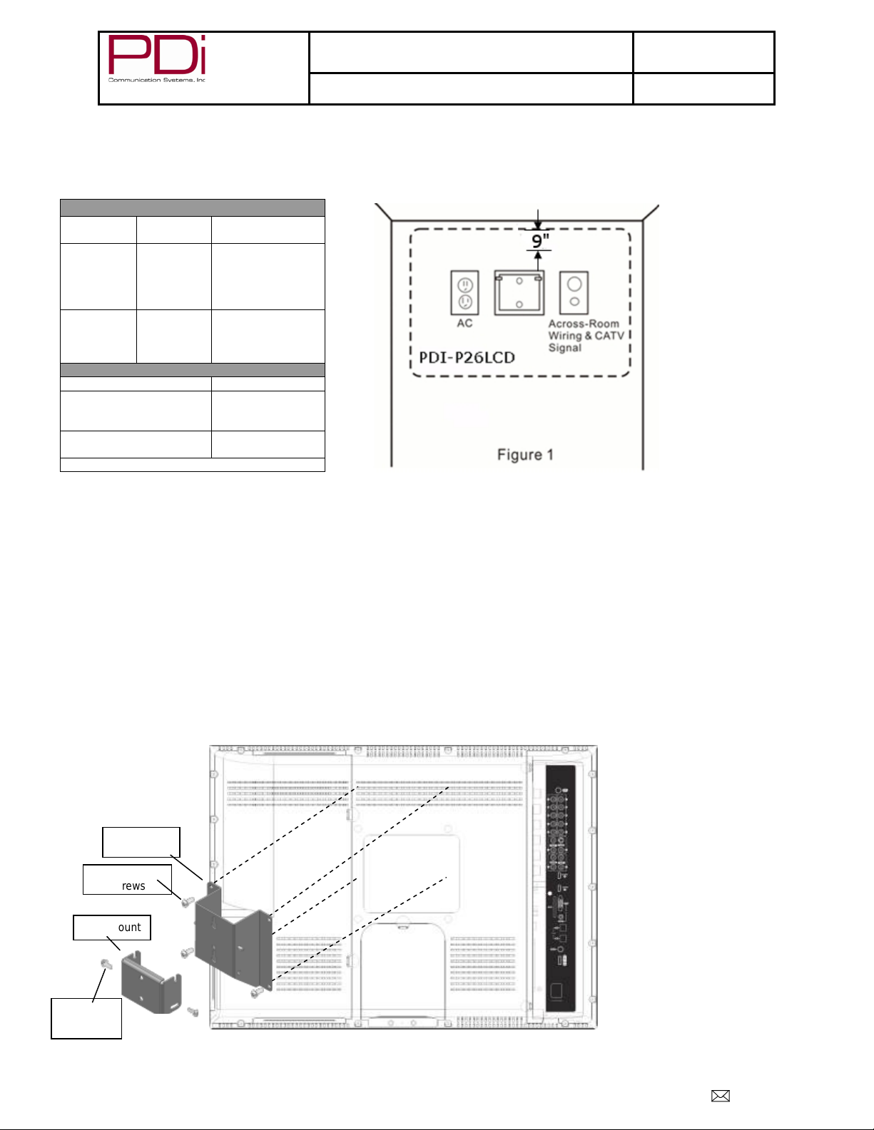
Wall MOUNTING STANDARD WALL BRACKET for PDI-P26LCD TV
The PDI-P26LCD TV is mounted to the wall with a PD168-103 mount (Not supplied wit h TV) or a PD168-203 mount (Not supplied with TV). The
PD168-203 mount is a heavy duty mount and is to be used if a DVD or an IPT module is going to be mounted on the P26. A PD168-203 wall mount
connects to a PD181-674 LCD mount. A PD168-103 wall mount connects to a PD181-597 LCD mount.
Purpose
P26LCD TV to wall
PD168-103 PD181-597
PD168-203 PD181-674
PDIPPBHSCS103250
PDIPPHMSM4X76
1. Refer to Figure 1. Select a location on the wall
approximately 9 inches below the ceiling.
NOTE: DO NOT locate AC, Across-Room
Wiring, and CATV Signal outlets below the
Wall Bracket’s location as it will cause
clearance issues and interfere with the TV’s
cabinet when mounted to the bracket.
2. Position the wall mount and locate the two
mounting holes. Secure the bracket to the wall
(mounting hardware is not included).
3. Refer to Figure 2. Position the LCD mount on
without DVD
and/or IPT
P26LCD TV to wall
with DVD and/or
Proof PIH Button
Attach with the four M4 screws (PDIPPHMSM4X76) that
are provided.
4. Mate the LCD mount to the wall mount, making sure the
pivot pins are retained in the slots.
5. Secure with two 10x32 Pilfer screws
(PDIPPBHSCS103250).
6. The TV’s tilt can be adjusted by loosening both Pilfer
screws, adjusting tilt, and then tightening the screws.
Mounting Connections
Screws
PDi Communication Systems, Inc. 40 Greenwood Lane Springboro, Ohio 45066 USA PH 1-800-628-9870 FX 937-743-5664
Page 5
MODEL NUMBER:
PDI-P26/ P32/ P40 LCD
Document Number:
Page 4 of 9
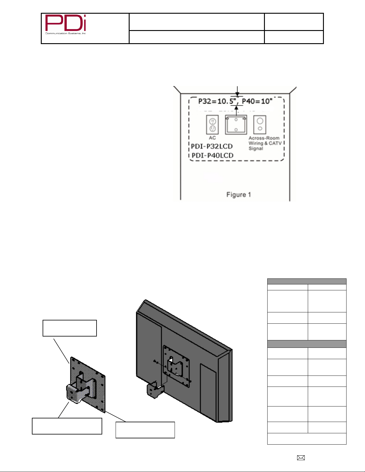
1. Refer to Figure 1. For the PDI-P32LCD find a location on
Mounting Pieces
Part #
Part
200mm to
(1)
LCD Mounting
Bracket (1)
HD Extended
(1)
Screws and Washers
PDIPPHMS103
238
10-32X3/8
PPHMS (2)
#10 Internal
Washer (6)
PDIPPHMSM4
X76
M4-.7X6mm
PPHMS (4)
¼” lock
washer (1)
Numbers in parenthesis represent
quantity
Figure 2
PD181-672: 200mm to
100mm Adapter Plate
PD181-596: LCD
Mounting Bracket
PD181-674: HD Extended
LCD Tilt Clevis
Better Solutions Are Within Reach
TM
Quick Start Guide
PD196-145R3
Wall Mounting for PDI-P32LCD TV and PDI-P40LCD TV
The PDI-P32LCD and PDI-P40LCD TVs require a PD181-672 200mm to 100mm Adapter Plate (N ot suppl i ed with TV), a PD181-596
LCD Mounting Bracket (Not supplied with TV), and a PD181-674 HD Extended LCD Tilt Clevis (Not supplied with TV) to be mounted
to the wall.
the wall 10.5 inches below the ceiling to mount the HD
Extended LCD Tilt Clevis (wall mount). For the PDIP40LCD, the location will be 10 inches below the ceiling.
NOTE: DO NOT locate AC, Across-Room
Wiring, and CATV Signal outlets below the
Wall Bracket’s location as it will cause
clearance issues and interfere with the TV’s
cabinet when mounted to the bracket.
2. Position the HD Extended LCD Tilt Clevis and locate two
3. Refer to Figure 2. Attach the LCD mount to adapter plate
4. Position the mounting bracket and adapter plate on the LCD
mounting holes. Place one of the supplied ¼” flat washers
(PDIFW25) and the ¼” lock washer (PDISLW25) on a ¼”
screw (not included) and insert it into the top mounting hole
of the clevis. Secure the clevis to the wall. Place the other
supplied ¼” flat washer on another ¼” screw and insert it in
the bottom mounting hole. Secure it to the wall and tighten
both screws.
using the four M4 screws (PDIPPHMSM4X76) and four #10
Internal Tooth Lock washers (PDIITLW10).
NOTE: The side with the four hex sides will
go toward the back of the set.
TV cabinet. Attach with the four M6 screws
(PDIPPHMSM6X110) that are provided.
5. Mate the mounting bracket to the clevis making sure
the resting pins are inserted in the two notches at the
front of the clevis. Secure with the two 10x32 screws
(PDIPPHMS103238) and the two remaining Internal
Tooth Lock washers.
6. The TV’s tilt can be adjusted by loosening both Pilfer
Screws, adjusting tilt, and then tightening the screws.
Mounting Connections
PD181-672
PD181-596
PD181-674
PDIITLW10
PDIPPHMSM6
X110
PDIFW25
PDISLW25
100mm
Adapter Plate
LCD Tilt Clevis
Tooth Lock
M6-1X10mm
PPHMS (4)
¼” flat washer
(2)
PDi Communication Systems, Inc. 40 Greenwood Lane Springboro, Ohio 45066 USA PH 1-800-628-9870 FX 937-743-5664
Page 6
MODEL NUMBER:
PDI-P26/ P32/ P40 LCD
Document Number:
Page 5 of 9
SPEAKER
DATA / SWITCH
COMMON
SPEAKER
DATA / SWITCH
COMMON
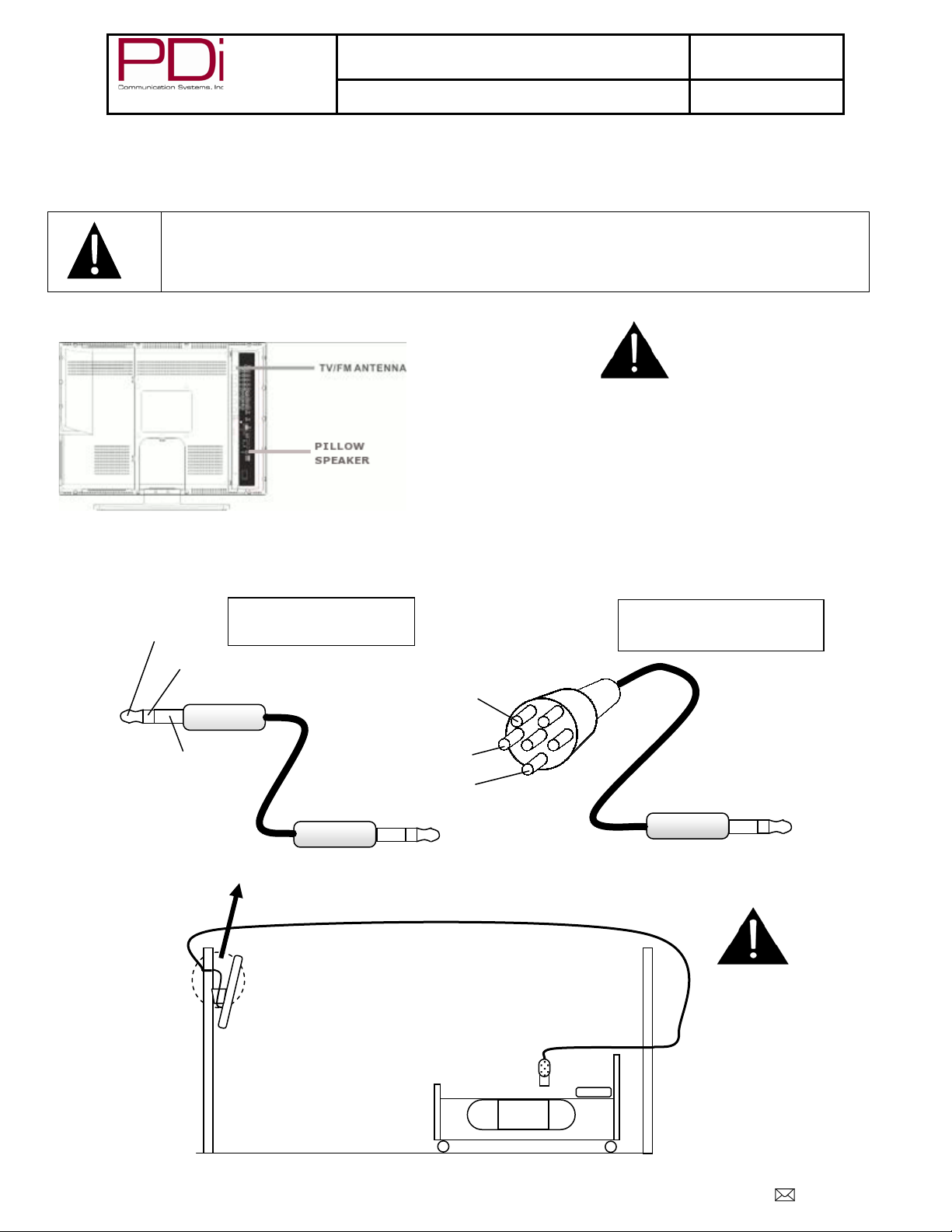
¼” to 6-Pin Jumper Cable
¼” to ¼” Jumper Cable
PD106-417
occur.
result to the TV.
OR
Better Solutions Are Within Reach
TM
Quick Start Guide
PD196-145R3
Pillow speaker
A ¼” stereo-style pillow speaker (pendant control) jack is located on the TV’s connector panel on the backside. This TV is designed to
work with either a digital pillow speaker that generates digital-style control codes or a single-button analog (switch-style) pillow speaker.
A rear panel mounted switch allows use of different brands of pillow speakers and supports the major brands: Zenith, Philips, and RCA.
CAUTION: Confirm the pillow speaker type and set the side switch appropriately BEFORE
connecting the pillow speaker to the TV. Failure to follow this procedure could result in damage to
the pillow speaker and/or TV.
Pillow Speaker and Antenna Connection
Across-Room Wiring
NOTE: A Jumper Cable is NOT supplied with the TV and must be ordered separately.
CAUTION: Some hospital
cable systems provide
power voltage on the coaxial
cable. This TV is NOT
designed to be powered via
a coaxial cable. DO NOT
connect to a powered
coaxial cable. Damage will
PD106-416
WARNING: DO NOT connect
the pillow speaker circuit
Common to earth ground.
Grounding of the Common will
defeat the isolation circuitry of
the TV and possibly expose
the patient to harmful shock
currents should a wiring fault
PDi Communication Systems, Inc. 40 Greenwood Lane Springboro, Ohio 45066 USA PH 1-800-628-9870 FX 937-743-5664
Page 7
MODEL NUMBER:
PDI-P26/ P32/ P40 LCD
Document Number:
Page 6 of 9
DISABLED – This is like a mechanical key lock. The
Better Solutions Are Within Reach
TM
Quick Start Guide
PD196-145R3
Programming
A programming remote control (PD108-420) is used to perform all setup operations for the TV.
NOTE: The following instructions assume you have correctly mounted the TV, wired an external pillow speaker, and connected
an RF coax cable signal, and AC power cord to the TV.
Service Levels Setup
The PDI-P26/P32/P40LCD TV contains four separate service levels, allowing the hospital to offer basic and enhanced viewing. The
current service level can be quickly determined by accessing the SETUP menu using the remote control. Service Level can be
changed to any of the 4 levels at any time by entering the SETUP menu and changing the Service Level setting.
TV can be turned OFF and ON, but cannot be used
for viewing programs. A standard message appears
on a black screen.
FREE – This lets patients watch hospital education
and information channels without renting the TV.
The channels containing programming for no charge
are typically programmed into this level of service.
This is the factory default setting for Service Lev el.
BASIC – This service typically allows additional
channels beyond those offered in the FREE level.
PREMIUM – This is the highest service level with
typically the most channels available for viewing.
Signal
Four different tuning types are available depending upon the healthcare facility’s signal style. Selection of the correct signal type is
required for the TV to recognize all possible channels and before any channel programming can begin.
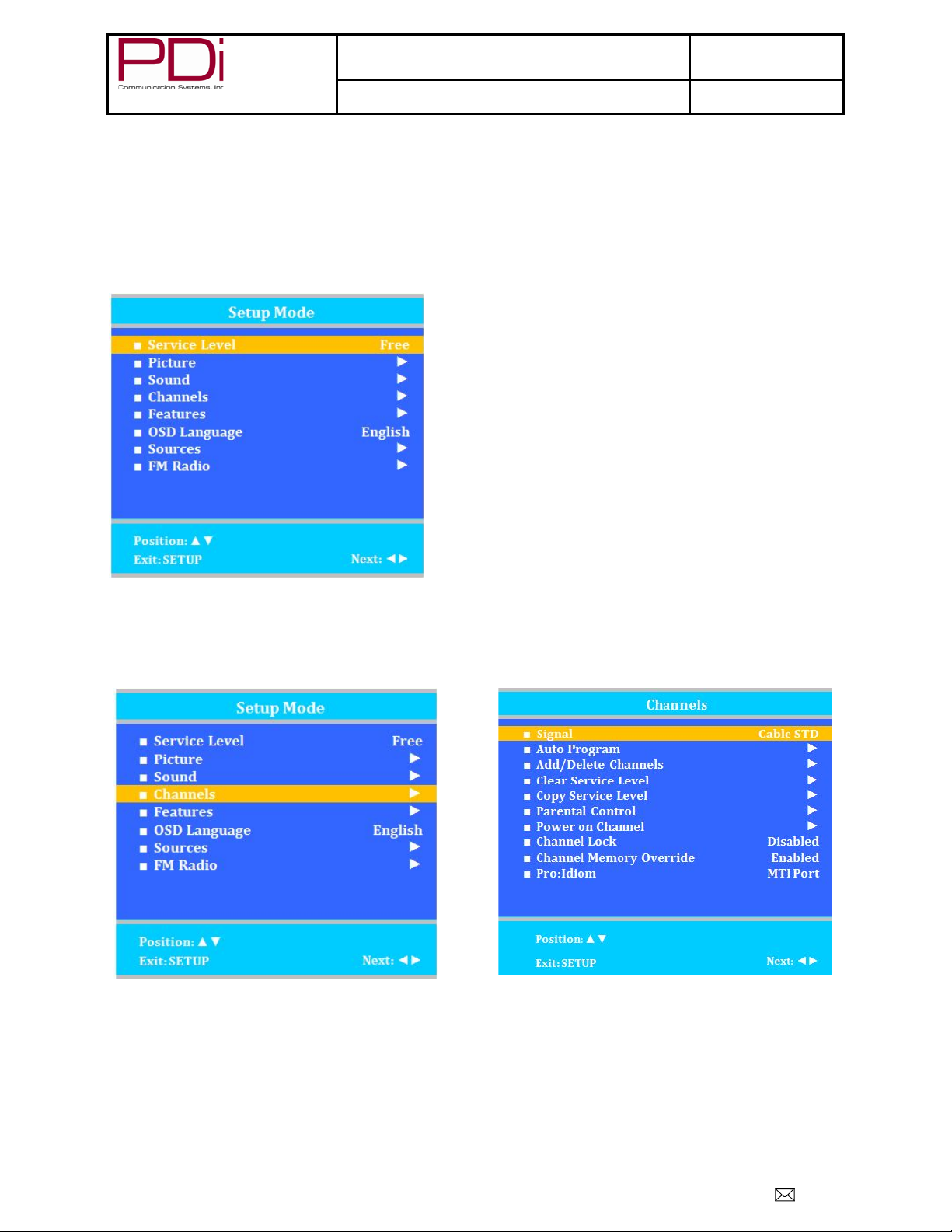
1. Press SETUP
2. Press CH▲ or CH▼ to highlight Channels.
3. Press VOL► to enter the Channels menu.
4. Press CH▲ or CH▼ to highlight Signal.
5. Press VOL◄ or VOL► to select Air, Cable STD, Cable IRC, or Cable HRC.
NOTE: Most hospitals use the Cable STD signal style.
6. Now perform Auto Program or Add/Delete Channels to adjust the channels.
PDi Communication Systems, Inc. 40 Greenwood Lane Springboro, Ohio 45066 USA PH 1-800-628-9870 FX 937-743-5664
Page 8
MODEL NUMBER:
PDI-P26/ P32/ P40 LCD
Document Number:
Page 7 of 9
Better Solutions Are Within Reach
Auto Program
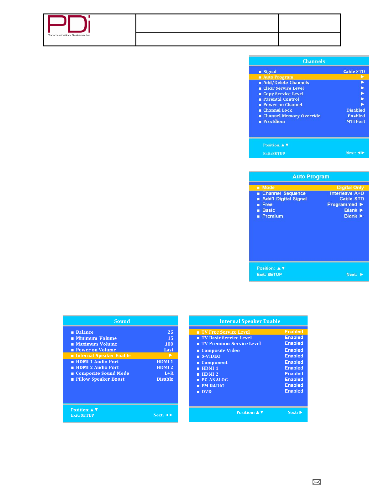
The TV automatically scans each available channel for activity . Channe ls that dis play
activity are memorized into the selected Service Level.
1. After setting Signal, press CH▲ or CH▼ to highlight Auto Program.
2. Press VOL► to select it.
3. On Mode, press VOL◄ or VOL► to select the scope of channel scanning.
4. Press CH▲ or CH▼ to highlight Channel Sequence.
5. Press VOL◄ or VOL► to select the channel sequence in which the channels
are displayed.
6. If you want to allow the TV to program additional digital channels, press CH▲
or CH▼ to highlight Add. Digital Signal. Press VOL◄ or VOL► to select Air.
NOTE: This feature is only available if Mode is set to Digital Only or
Analog and Digital.
7. Press CH▲ or CH▼ to highlight the Service Level (Free, Basic, or Premium)
you wish to program. The menu displays the current programming status of
each level as either Programmed or Blank.
8. Press VOL► to start auto programming.
9. A confirmation menu will appear before proceeding. Press CH▲ to start auto
programming. Press CH▼ to cancel the operation. The TV now will search all
available channels. Auto programming requires several minutes to complete.
10. Press SETUP to return to the previous menu. To exit, press SETUP until the
programming menus disappear .
Internal Speaker Enabled
The speakers inside the TV’s cabinet normally are enabled. Sound is also routed externall y to an attac hed pil low speake r.
1.
Enter the Sound menu
2. Press CH▲ or CH▼ to highlight the component you want to change.
3. Press VOL◄ or VOL► to select Enabled or Disabled.
4. Press SETUP to return to the previous menu.
TM
Quick Start Guide
Analog Only: TV searches for analog channels only.
Digital Only: TV searches for digital channels only.
Analog and Digital: TV searches for both analog and digital channels.
Interl eav e A+D: Cha nne ls are disp lay ed in the order of channel
number.
All A then D: All digital channels are displayed after all analog
channels.
NOTE: A programmed service level can also be reprogrammed if
desired.
NOTE: Digital channel auto programming may take longer than 10
minutes to complete.
PD196-145R3
PDi Communication Systems, Inc. 40 Greenwood Lane Springboro, Ohio 45066 USA PH 1-800-628-9870 FX 937-743-5664
Page 9
MODEL NUMBER:
PDI-P26/ P32/ P40 LCD
Document Number:
Page 8 of 9
Better Solutions Are Within Reach
Minimum Volume
This sets the minimum volume level the TV can reach. For pillow speakers with an adjustment thumbwheel volume control, ALWAYS
set a minimum volume level for the TV. A minimum volume setting is usually not required for pillow speakers with dedicated Volume
Up and Down buttons.
NOTE: Setting this level to any value other than 0 guarantees that some level of sound will always be heard when
the TV is operating.
1. In the Sound menu, press CH▲ or CH▼ to highlight Minimum Volume.
2. Press VOL◄ or VOL► to select the preferred minimum volume.
3. Press the SETUP button to return to the preceding menu.
Power on Volume
This sets the initial volume the TV starts at upon powering on. Once the TV is on, the volume can be set to any allowable level.
In Sound menu, press CH▲ or CH▼ to highlight Power on Volume.
1. Press VOL◄ or VOL► to select the preferred volume when the TV turns on.
NOTE: Setting the level to LAST causes the TV to remember the last volume level used by the TV prior to turning off.
2. Press the SETUP button to return to the preceding menu.
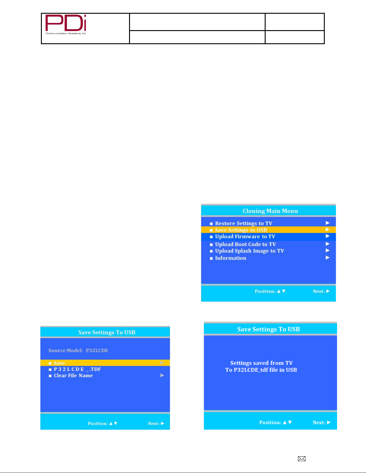
Cloning
Cloning allows quick programming of a TV using a USB Flash Drive. First a specimen TV is hand-programmed using a programming
remote control (PD108-420) with channels, sound, and other settings. While the TV is “ON” a USB thumb drive is inserted into that
TV’s USB port, the specimen TV’s setup written to the thumb drive, and then the thumb drive is removed to program other
televisions. One thumb drive can be used to program an entire hospital of televisions.
Save Settings to USB
1. Turn the TV On.
2. Insert thumb drive.
3. Press CH▼ to highlight Save Settings to USB.
4. Press VOL► to enter the menu.
5. Press CH▲ to initiate Clone mode.
6. A status message indicates Successful Saving of TV information to
the USB.
7. Remove the USB Disk from the TV.
PD196-145R3
TM
Quick Start Guide
PDi Communication Systems, Inc. 40 Greenwood Lane Springboro, Ohio 45066 USA PH 1-800-628-9870 FX 937-743-5664
Page 10
MODEL NUMBER:
PDI-P26/ P32/ P40 LCD
Document Number:
Page 9 of 9
Better Solutions Are Within Reach
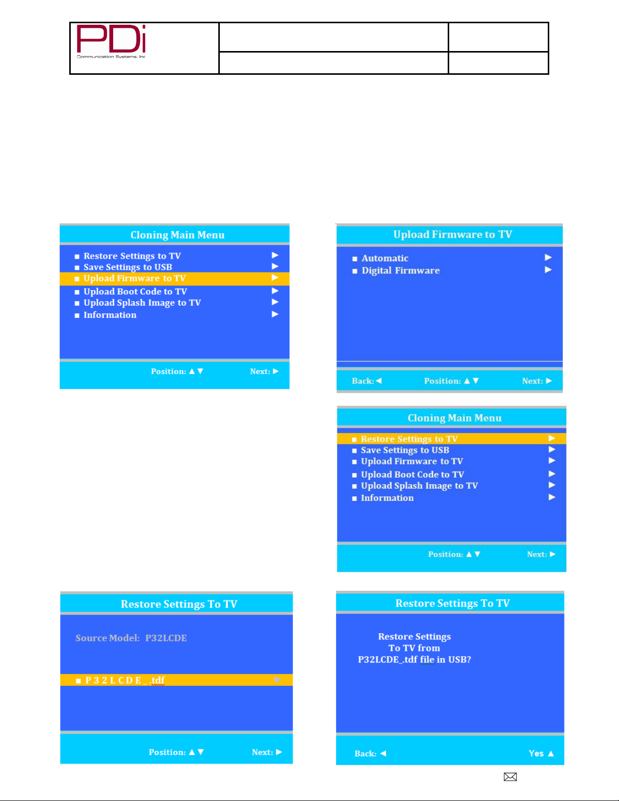
Upload Firmware to TV
Files must be unzipped before downloading.
1. Turn the TV On.
2. Insert thumb drive.
3. Press CH▼ to highlight Upload Firmware to TV.
4. Press VOL► to enter the menu.
5. Press CH▲ or CH▼ to choose type of uploading.
6. A confirmation screen will appear. Choose Yes▲ to begin upload.
7. A status line indicates Successful Saving of TV information to the USB Disk.
8. Uploading will take a short time. Do not eject USB while uploading.
9. TV will restart upon completion and “Firmware Upgrade is done” will appear.
10. Remove the USB Disk from the TV.
Restore Setting to TV
1. Turn the TV On.
2. Insert the thumb drive.
3. Press CH▲ or CH▼ to highlight Restore Settings to TV.
4. Press VOL► to enter the menu.
5. Press CH▲ or CH▼ to choose desired TV setting to restore.
6. Press CH▲ to initiate Clone mode.
7. TV will restart after restore is complete.
8. Remove USB disk from the TV
9. Verify correct setup of the TV.
PD196-145R3
TM
Quick Start Guide
PDi Communication Systems, Inc. 40 Greenwood Lane Springboro, Ohio 45066 USA PH 1-800-628-9870 FX 937-743-5664
 Loading...