

Page 1
pco.
pco.
user manual
ultraviolet
Page 2
PCO asks you to read this manual carefully before using the
pco.ultraviolet camera system and follow the instructions.
ntact us for further questions or comments.
Co
telephone +49 (0) 9441 2005 50
fax +49 (0) 9441 2005 20
email [email protected]
postal address PCO AG
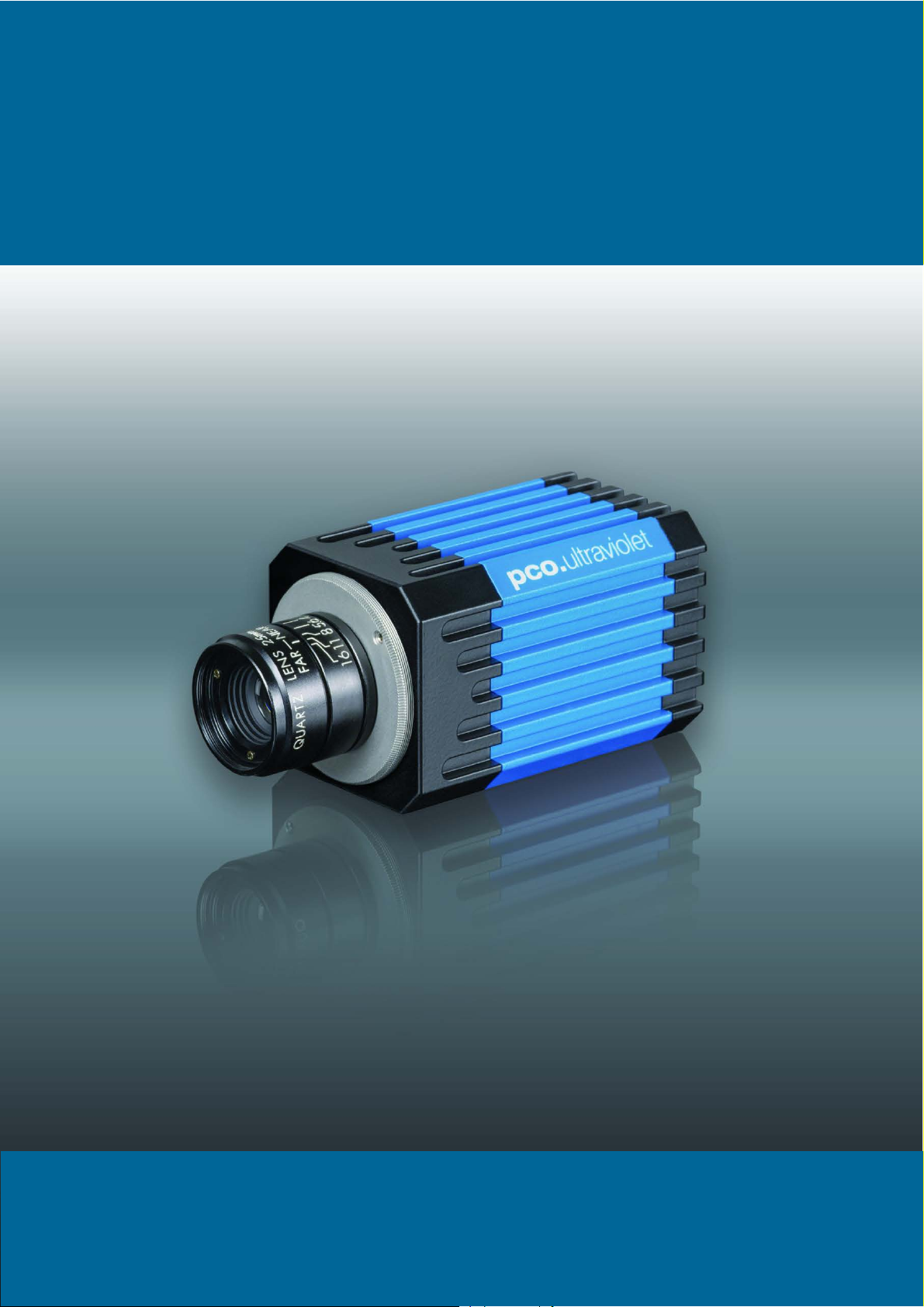
cover picture shows a typical pco.ultraviolet camera system.
The
Donaupark 11
93309 Kelheim, Germany
The lens is sold separately.
opyright © 2017 PCO AG (called PCO hereinafter), Kelheim, Germany. All
C
rights reserved. PCO assumes no responsibility for errors or omissions in
these materials. These materials are provided as is without warranty of any
kind, either expressed or implied, including but not limited to, the implied
warranties of merchantability, fitness for a particular purpose, or noninfringement. PCO further does not warrant the accuracy or completeness of
the information, text, graphics, links or other items contained within these
materials. PCO shall not be liable for any special, indirect, incidental, or
consequential damages, including without limitation, lost revenues or lost
profits, which may result from the use of these materials. The information is
subject to change without notice and does not represent a commitment on
the part of PCO in the future. PCO hereby authorizes you to copy documents
for non – commercial use within your organization only. In consideration of
this authorization, you agree that any copy of these documents, which you
make, shall retain all copyright and other proprietary notices contained
herein. Each individual document published by PCO may contain other
proprietary notices and copyright information relating to that individual
document. Nothing contained herein shall be construed as conferring by
implication or otherwise any license or right under any patent or trademark of
PCO or any third party. Except as expressly provided, above nothing
contained herein shall be construed as conferring any license or right under
any PCO copyright. Note that any product, process, or technology in this
document may be the subject of other intellectual property rights reserved by
PCO, and may not be licensed hereunder.
eleased: September 2017 © PCO AG
R
pco.ultraviolet User Manual V2.13 © PCO AG, Germany
Page 3

TABLE OF CONTENTS
TOP
TABLE OF CONTENTS
1. INTRODUCTION 5
1.1 INTENDED USE 5
2. SAFETY INSTRUCTIONS 6
3. SYSTEM COMPONENTS 7
4. INSTALLATION 8
4.1 DRIVER 8
4.2 CAMWARE 9
5. QUICK START 10
5.1 PREPARATION 10
5.2 START 10
5.3 YOUR FIRST IMAGE 11
6. CAMWARE 4 SOFTWARE 12
6.1 CHAPTER OVERVIEW 12
6.2 CAMERA OVERVIEW / LIST 13
6.3 CAMERA PROPERTIES 15
6.3.1 TIMING 16
6.3.2 IMAGE SIZE 17
6.3.3 SENSOR CONTROL 18
6.3.4 RECORDING CONTROL 20
6.3.5 STATUS 20
6.3.6 CONVERT CONTROL DIALOG 21
6.4 IMAGE OVERLAY 22
6.5 RECORDER TOOLS 23
6.6 VIEW WINDOW 25
6.7 RECORDER (IMAGES) 26
6.8 SETTINGS OVERVIEW 28
6.8.1 AUTO SAVE 29
6.9 CAMWARE MENU TABS & FEATURES 31
6.9.1 DEMO MODE 31
6.9.2 FILE MENU 32
6.9.3 CAMERA MENU 34
6.9.4 ACQUISITION MENU 35
6.9.5 VIEW MENU 35
6.9.6 WINDOW MENU 37
6.9.7 HELP MENU 37
6.9.8 RIGHT-CLICK MENU 38
6.9.9 ADDITIONAL FEATURES 40
3
Page 4

APPENDIX 41
A1 TECHNICAL DATA 42
A1.1 DATA SHEET 42
A1.2 QE CURVE 43
A1.3 TRIGGER INTERFACE 43
A1.4 MECHANICAL DIMENSIONS 44
A1.5 NO INPUT WINDOW 44
A1.6 REVERSE WITH CAPTION 45
A2 IMAGE FILE FORMATS 46
A3 CUSTOMER SERVICE 48
A3.1 SERVICE 48
A3.2 MAINTENANCE 48
A3.3 TROUBLE SHOOTING 49
A3.4 RECYCLING 50
A4 INDEX 51
ABOUT PCO 52
4
Page 5
1. INTRODUCTION
• UV detection
• powerline control
• low light level imaging
• corona discharge
• hyperspectral imaging
• combustion imaging
• wafer inspection
• high resolution microscopy
•
•
• scientific imaging
• spectroscopy
• material testing
• luminescence spectroscopy
• industrial applications
• industrial OEM applications
1. INTRODUCTION
and associated electronics. In addition, a proprietary offset control
algorithm has been developed which provides very high offset
stability, regardless of ambient temperature or signal changes,
ensuring accurate and repeatable quantitative data over long periods
of time.
The camera’s main features are:
Advantages of the pco.ultraviolet
Features
This high performance 14 bit CCD camera system has
an extraordinary quantum efficiency of up to 40% at a
wavelength of 193nm. This sensitivity is true sensor
performance, without any additional coating. At the
heart of the camera is a FPGA processor allowing for
sophisticated control and accurate timing of the CCD
1.1 INTENDED USE
•
excellent resolution of 1392 x 1040 pixel
•
superior UV sensitivity of up to 40% QE @ 193nm
•
superior low noise of 7 … 9 e- rms
•
14 bit dynamic range: 1750:1 (65dB), 3000:1 (69,5dB) binning
•
excellent DSNU at long exposure times
•
outstanding offset stability and control (< 1 count)
•
hot pixel correction integrated
•
USB 2.0 interface
This camera system is designed for use by technicians, engineers
and scientists. It is a scientific measuring instrument, which provides
images. The camera may only be used according to the instructions
of this manual. Provisions, limitations and operating conditions stated
in this manual must be respected. Unauthorized modifications or
alterations of this device are forbidden for safety reasons.
Areas of Application
mask inspection
5
machine vision
Page 6
NOTICE
NOTICE
NOTICE
NOTICE
NOTICE
NOTICE
DANGER
WARNING
CAUTION
CAUTION
2. SAFETY INSTRUCTIONS
Please read the safety instructions completely and follow them
always.
DAMAGED POWER CABLE OR POWER PLUG
Danger to life due to electric shock.
Each time the camera is used, check the power cable for
damage.
ELECTRIC SHOCK WARNING DUE TO VOLTAGE PARTS INSIDE
Risk of injury due to electric shock.
Do not open the camera.
MOISTURE
Risk of injury due to electric shock if moisture enters the camera.
To avoid the risk of water condensation, protect the camera
against extreme changes of ambient temperature.
TRIPPING HAZARD
Risk of injury from tripping over loose cables.
Never position the cable in a way that it could become a
tripping hazard.
HUMIDITY, DUST OR RADIATION
Humidity, dust or X-rays could damage the camera.
Never operate the camera in humid or dusty environments
or in places with high levels of x-ray radiation.
SHOCK & VIBRATION
To prevent damage to the camera, the system must be kept stable
and protected against strong jolts or vibrations.
Use the mounting threads of the camera to mount the
camera stable.
LENS MOUNTING
Do not force the lens onto the camera.
To protect the lens connector thread from damage, use
minimal force when attaching a lens to the camera.
LIQUIDS DAMAGE CAMERA
If liquids have penetrated the device.
Immediately switch off the camera, separate it from power
DAMAGED CAMERA HOUSING
If the camera has been dropped or the casing is damaged.
IF CAMERA IS NOT WORKING PROPERLY
If, after thoroughly reviewing the instruction manual, the device is still
not operating properly.
line and contact our customer support.
Immediately switch off the camera, separate it from power
line and contact our customer support.
Immediately switch off the camera, separate it from power
line and contact our customer support.
6
Page 7
3. SYSTEM COMPONENTS
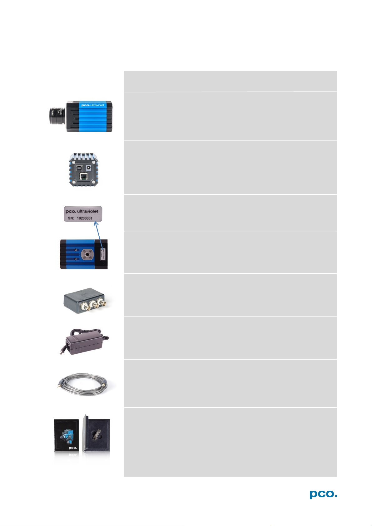
The camera system includes the following parts.
DC Power Jack
USB Cable
3. SYSTEM COMPONENTS
Camera
C-mount optical connection:
The distance between the front edge of the c-mount and the sensor is
17.52 mm. The standard for C-mount lenses and adapters.
(connects to power supply)
USB 2.0 Connector (connects to PC)
RJ11 (connects to I/O device)
Serial Number Tag
Mounting Thread
1/4"- 20 UNC
Trigger Interface (I/O Device)
Proprietary RJ11-BNC connector for Trigger/Busy/Exposure signals
Power Supply
AC to 12V/DC power supply
USB-A/USB-B cable (5 m)
Digital Camera Tools (USB flash drive content)
• CamWare: software for camera control & image acquisition
• Camera driver & tools
• Software development kit (SDK) & demo programs in C and C++
7
Page 8
• Clock speed > 1.6 GHz
• 1280 x 1024 pixel
• RAM > 512 MB
• Windows 7
• USB 2.0
1
2
1
2 3 4
3
4
4. INSTALLATION
You will find all necessary files on the accompanying USB flash drive.
You may also download the latest versions of our software, camera
driver and third party software drivers from our Website
(www.pco.de).
Minimum system requirements:
4.1 DRIVER
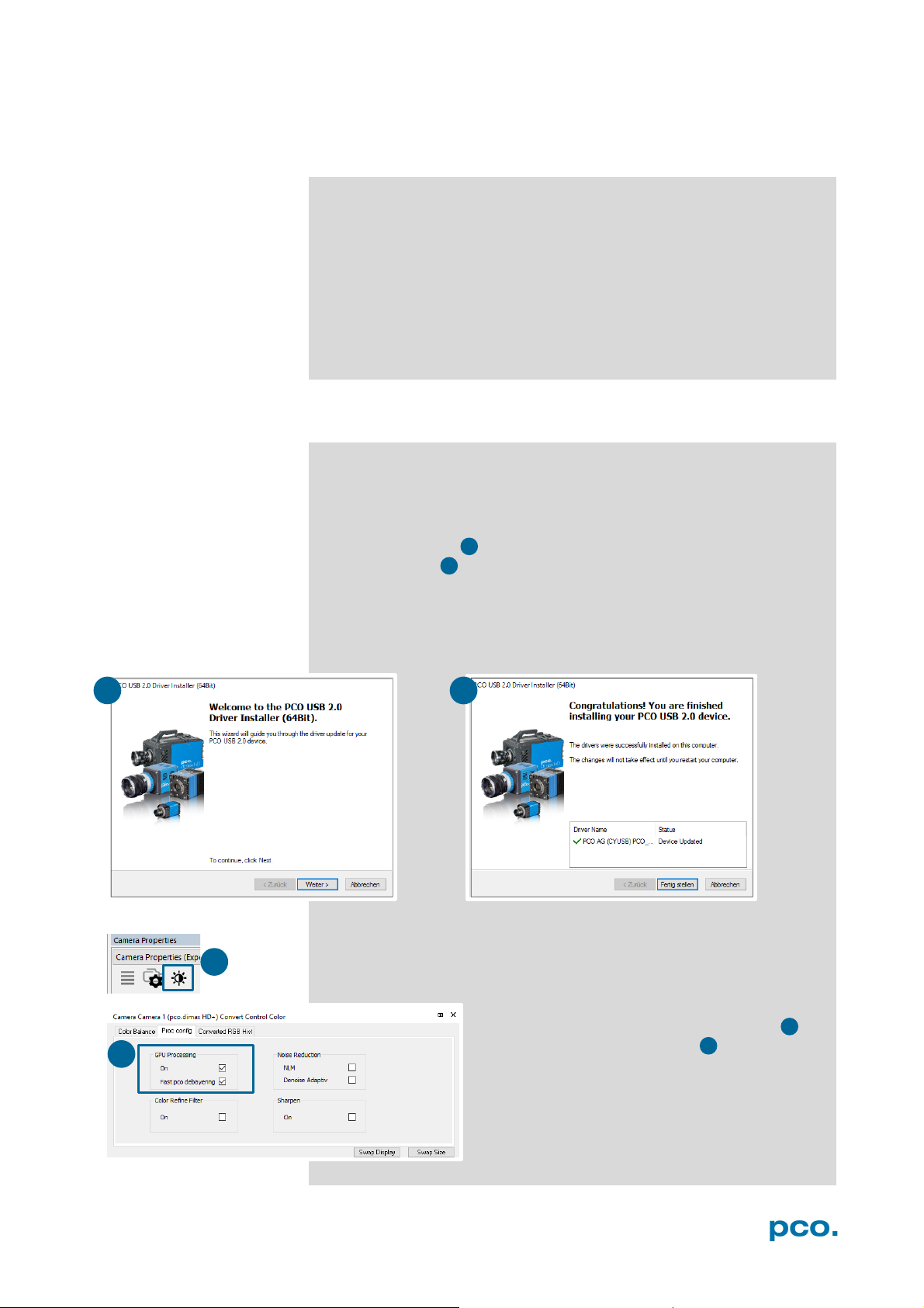
Start the USB 2.0 driver installation from your USB flash drive.
Don’t connect the camera to your computer before driver is
completely installed.
Run the provided installation file and follow the instructions of the
installation wizard.
After finishing the driver installation wizard connect your
pco.pixelfly camera to its power supply and via enclosed USB 2.0
cable to your computer.
The first time the camera is connected via USB to a computer,
Windows will notify the user that a new device has been detected.
NVIDIA Cuda Driver:
Please update your NVIDIA driver for Camware 4. In case of an old
driver version GPU Processing is not working. Therefore image
processing is slow.
resolution display
Please check if GPU Processing is activated by
having a look into the Proc config settings in
the Convert Control window (see Convert
Control chapter 6.3.7).
If GPU Processing is disabled and shown
grayed, please update your NVIDIA driver. Your
NVIDIA driver version must be at least 333.11 or
higher.
8
Page 9
4. INSTALLATION
1 2 3
4
1
1 2 3
4
4.2 CAMWARE
The Camware Windows application software enables to control every
camera parameter or setting. Images can be displayed on a monitor
and may be downloaded and stored. The USB flash drive contains
the installation files for the software for latest Windows operating
systems in 32 & 64 bit.
After a successful installation, you will find the program file Digital
Camera Toolbox in your program directory and a Camware 32 / 64
button on your desktop. Other helpful tools are also installed in the
same directory.
To uninstall the Camware program, please use the Software feature
under Windows’ System Control.
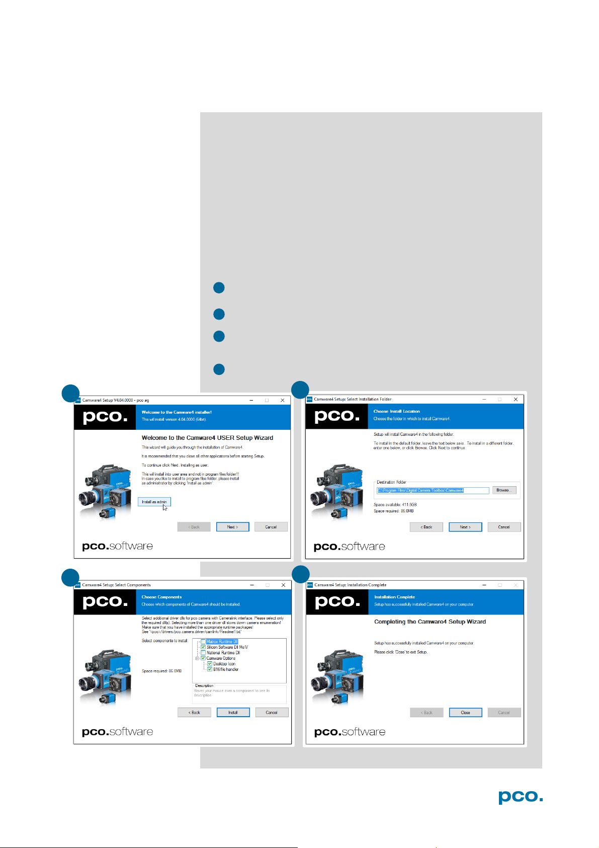
Please follow the installation wizard
- Install Camware as Admin to install to program folder, otherwise
it will be installed only to user folder
- Then choose install directory
- Choose components: Select additional drivers for Camera Link
Interface (not recommended for pco.ultraviolet)
- After the next two screens installation is complete
9
Page 10
NOTE
Always install latest Camware version to be able to use full
5. QUICK START
5.1 PREPARATION
In order to get familiar with your new camera and software it might be
helpful, first to aim the camera at an object easy to focus and visible
at normal light conditions.
• Computer is turned on
• Installation is finished (see chapter 4)
• An appropriate lens is attached (remove cap) or the camera is
attached properly to the microscope, spectrograph or other
scientific device
• Camera is connected to the PC
• Camera is connected to the power supply and ready
5.2 START
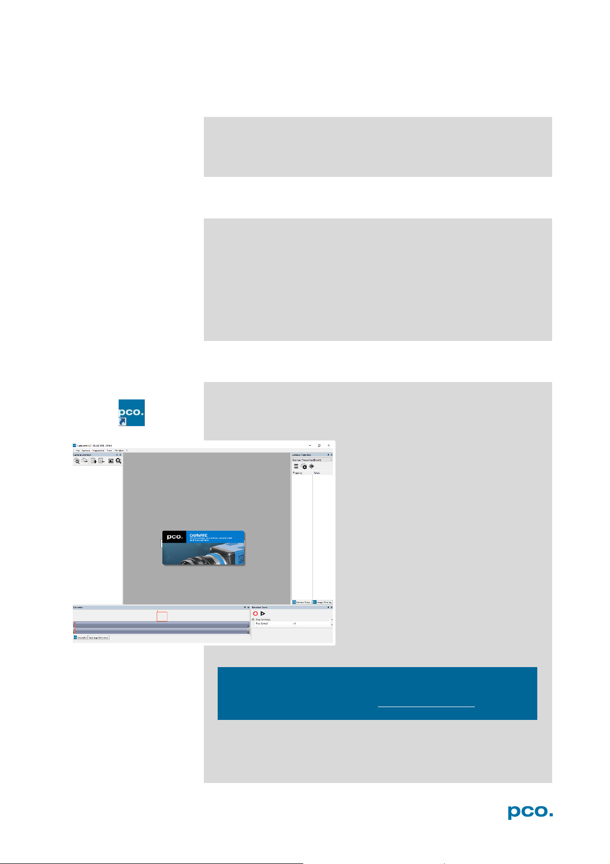
Start Camware and the graphical user interface will start up:
functionality of your pco camera (www.pco.de/support).
10
Page 11
5. QUICK START
NOTE
2 3 4
5
6
2 3 6 4 5
1
1
5.3 FIRST IMAGE
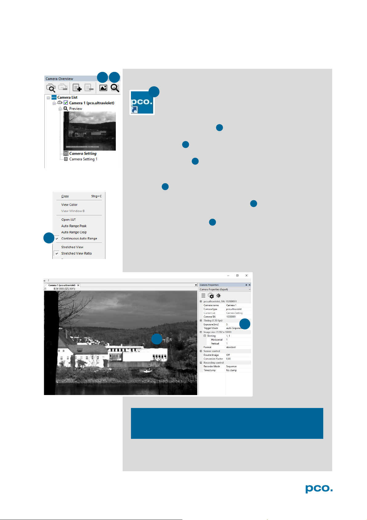
Please follow the instructions:
• Camware must be started
• A view window is shown automatically /or open a new one
• Start live preview
• Right-click in the view window and apply Continuous Auto
Range
• You may have to adjust exposure time , aperture and focus
• Now you should clearly see the object in the window
If you need to change
exposure time (e.g.
the image is still either
too dark or too bright),
please go to chapter
6.3.1.
For recording and
saving images, please
see chapter 6.3.4 and
chapter 6.7 for detailed
information.
Live preview: Useful for fast and easy camera adjustment and
focusing.
11
Page 12
6.2 Camera Overview/List
Preview / Connected cameras;
Recording profiles
6.3.1 Timing
Exposure time / Trigger modes
6.3.2 Image Size
Sensor format / Binning
6.3.3 Sensor Control
Double Shutter / Conversion factor
6.3.4 Recording Control
Recorder mode / Timestamp
6.3.5 Status
Electronics temperature
6.3.6 Convert Control Dialog
Contrast / Saturation / Gamma…
6.4 Image Overlay
Overlay for recorded images
6.5 Recorder Tools
Record / Play / Settings
6.6 View Window
View window functions
6.7 Recorder (Images)
Preview of recorded images
6.8 Settings Overview
Overview of all parameter settings /
Auto Save Dialog
6.9.1Demo Mode
No camera connected
6.9.2 File
Open / Save / Print files / Options /
file / Lookup table
6.9.3 Camera
Camera control / Close / Rescan
6.9.4 Acquisition
Live preview / Acquire sequence /
Rec. memory settings
6.9.5 View
New window / Convert control / Multi
window / Toolbar / Application look
6.9.6 Window
New / Close / Split window
6.9.7 Help
Logfiles / Support file / About
6.9.8 View window menu
Right-click: Zoom / Flip / Mirror /
Rotate…
6.9.9 Additional features
White Balance / Contrast / Short cut
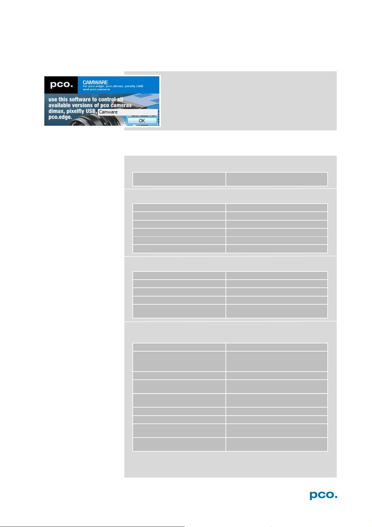
6. CAMWARE 4 SOFTWARE
PCO’s Camware is an outperforming software for camera
control, image acquisition and archiving of images in
various file formats. This chapter provides a detailed
description of all Camware functions.
Camware works with any kind of PCO camera. Visit PCO
website for the latest version of this software.
6.1 CHAPTER OVERVIEW
Chapter 6.2: lists all connected cameras
Chapter 6.3 Camera Properties: main dialog for all camera settings:
Chapter 6.4 / 6.5 / 6.6 / 6.7 / 6.8 describe the recording functions
Chapter 6.9 describes the tabs (File, Camera Acquisation, View,
Window, Help) the right-click menu and additional features.
Avi Codec Dialog / Direct record to
list
12
Page 13
6. CAMWARE 4 SOFTWARE
1
1 2 6
5
2
3
4
5
6
6.2 CAMERA OVERVIEW / LIST
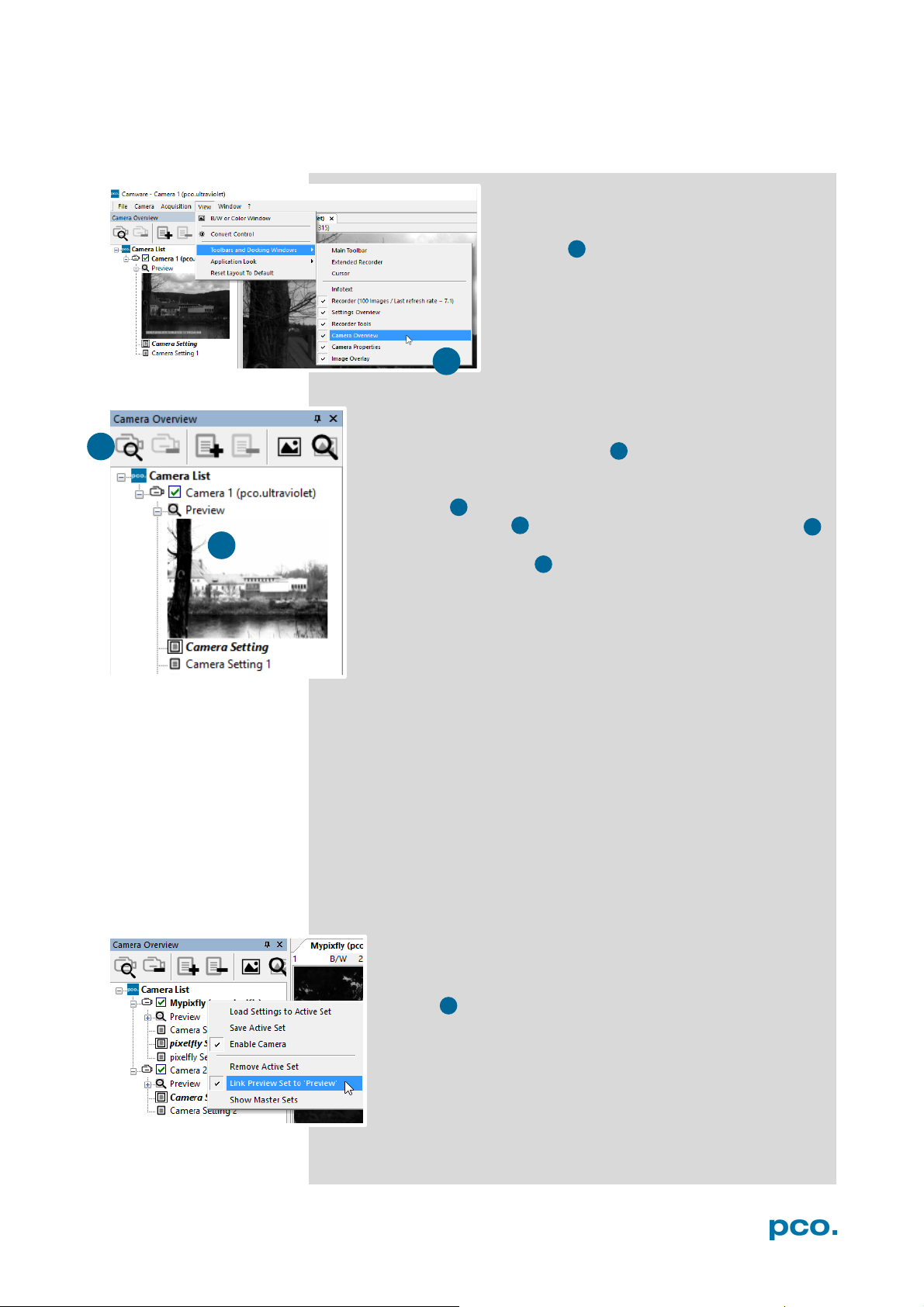
The Camera Overview window allows you to manage several
connected cameras. It displays a list of all connected PCO
cameras. Camware is able to scan 2 for connected cameras or
close a connected camera. It is possible to define several
different Settings for each camera (max. 30 sets per camera →
add new set 3 ).
New view windows 4 can be opened and the Live Preview 5
function can be started. When unfolded the Preview shows a
small preview window 6 (always monochrome) integrated to
the camera list.
Live preview facilitates the aperture and focus adjustment, allowing a
first look at your object. During live preview no images are saved into
the computer’s RAM.
If closed, the Camera Overview window can
be opened by selecting the View tab and
Toolbars and Docking Windows → Camera
Overview.
During Live preview Trigger and Acquire mode are set to Auto.
Camera Setting: All presettings, such as resolution and frame rate,
made in the Camera Properties (see 6.3) are saved to Camera
Settings. Define different Settings with different Preferences in
Camera Properties for each of your experiments. Settings can be
switched easily at any time (not during record) and copied to other
cameras.
Link Preview Set to ‘Preview’
With Link Preview Set to Preview activated, the Preview set
with its parameters always active when starting a Live
Preview 5 .
In case this function is deactivated the Live Preview always
shows live images with the parameters of your active setting.
This feature is beneficial if preview light conditions are
different from those in recording situations.
13
Page 14
1
2
3
1 2 3
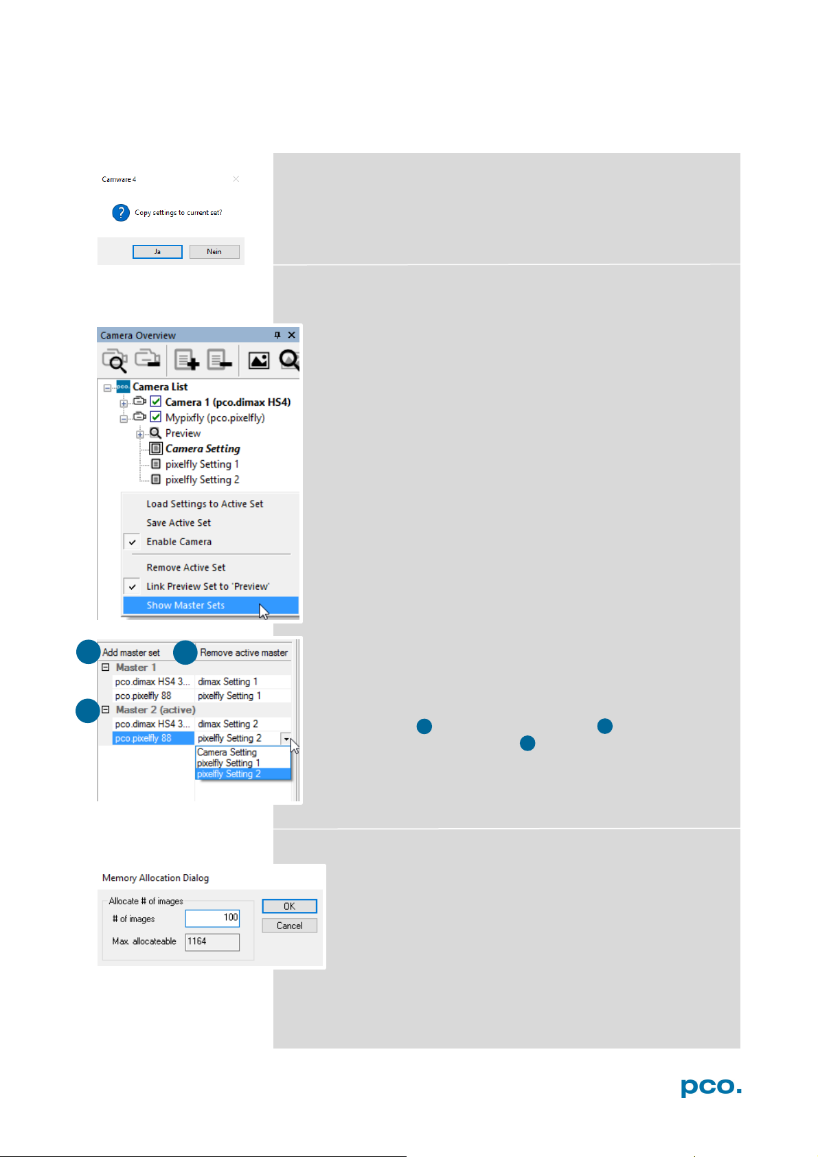
Click and drag camera setting: If you want to copy e.g. Camera
Setting 1 to Camera Setting 4, just drag Setting 1 to Setting 4 and
Camware will ask you if you want to copy the settings. It is possible
to copy each setting to every camera.
Master Sets
This function facilitates image acqusition with multiple cameras.
Defining two or more Master Sets allows easy switching between
different predefined settings for each camera during an
experiment. Each image acquisition or experiment can be
recorded with its own Master Set.
To display Master Sets, please right-click in the Camera
Overview window and select Show Master Sets.
Master Set window
Define different Master Sets. Select individual Camera Settings
within each Master Set.
Functions:
Add Master Set or Remove active master .
Activate it by clicking on one set .
Important Setting (for cameras without internal memory)
Memory Allocation Dialog
To change the number of recorded images in Camware,
open the Acquisition Tab (see 6.7.4) and choose Recorder
Memory Settings.
It sets the number of images recorded in one sequence. The
maximum is defined by approved RAM size.
14
Page 15
6. CAMWARE 4 SOFTWARE
1 2 3
1 2 3 4 4
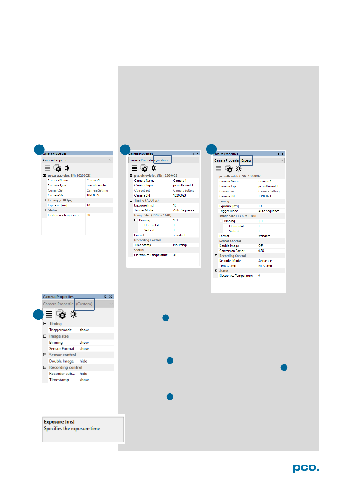
6.3 CAMERA PROPERTIES
The Camera Properties window in Camware is the main interface for
all camera settings. The active set selected within Camera List is
adjusted here.
The former topic Camera Control (known from Camware 3.x) and
Convert Control (see 6.3.5) can be opened additionally.
Three view options with various functions can be selected: Basic,
Custom and Expert.
Basic mode 1 only shows camera name, type, settings, serial
number and the exposure time. In Basic Mode the frame rate is
always calculated automatically based on the selected exposure
time, i.e. while exposure time is increased, frame rate decreases. It is
recommended for Camware beginners.
Custom mode 2 shows more setting possibilities and functions are
hidden or shown by the Custom Properties Button.
Additional to the Basic mode, Trigger mode, Image Size and
Recording control options are selectable.
Expert mode 3 (for advanced users) shows all possible Camera
Property settings.
An explanation for every setting is displayed below the properties
dialog.
15
Page 16
ttd
tid
2
trigger
busy
exposure
t
t
t
t
read
2
1
1
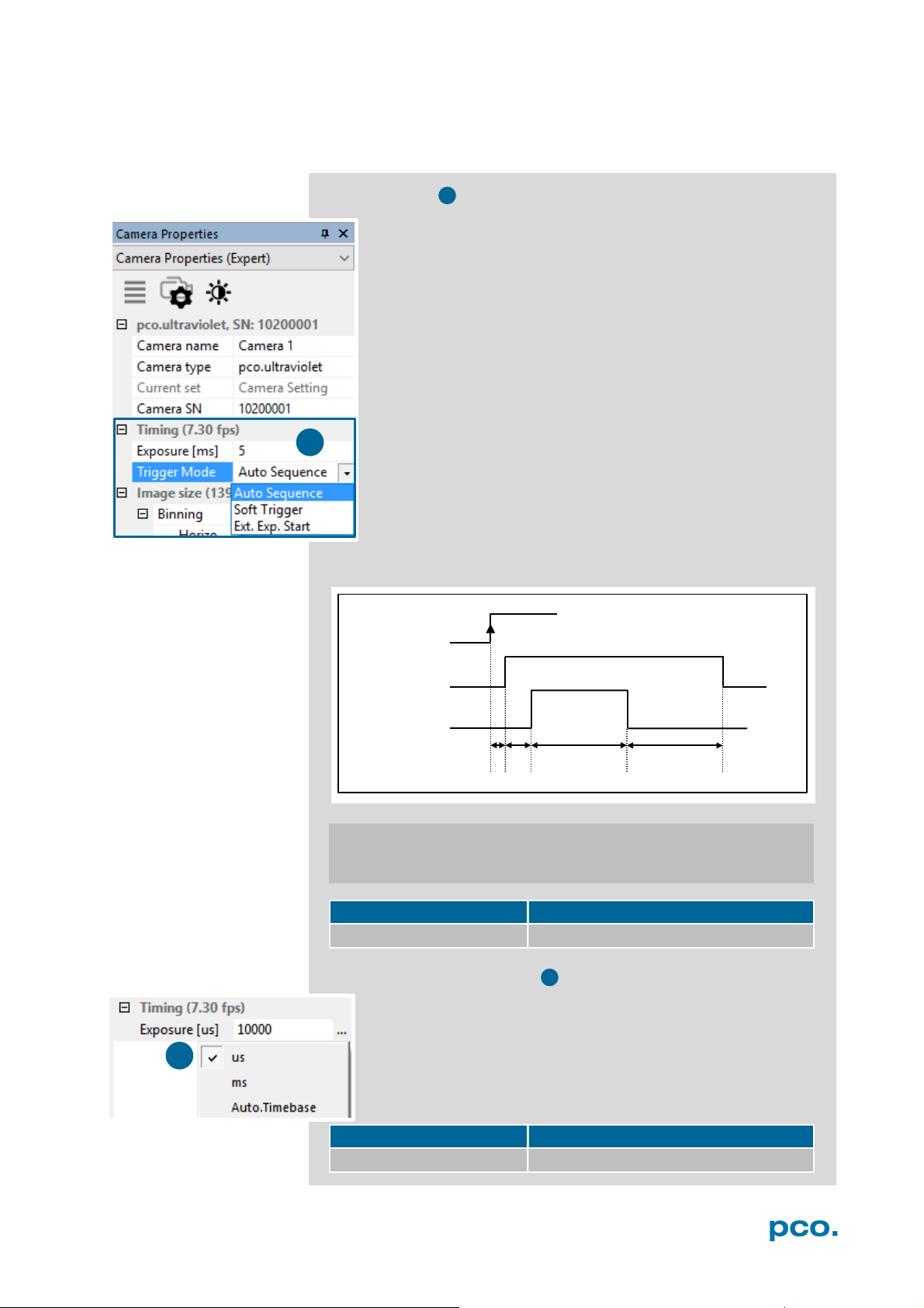
6.3.1 TIMING
Trigger Modes
Auto Sequence: the camera optimizes the image recording to
achieve the best possible frame rate.
In the Auto Sequence mode, the camera achieves the fastest
possible frame rate depending on the adjusted exposure time
and the required readout time.
Upon a start command images are recorded until a stop
command.
Software Trigger: single images are recorded by this Camware
command. The single image is acquired by pressing the Single
Trigger button. This button appears after pressing the Start
Record button (see 6.4). Other signals have no influence on this
operating mode.
External Exposure Start: image acquisition is triggered by an
external signal. The single trigger button acquires a single
image for a test.
In the External Exp. Start exposure control mode, single
image acquisition is started by the rising / falling edge of the voltage
signal at the BNC input (see appendix A1.3, A2).
td
id
exp
t
read
trigger acknowledge delay
readout time t
intrinsic delay
exposure time
exp
pixel clock intrinsic + trigger acknowledge delay
12 MHz 5.8 µs
Exposure Time and time-base
ITime-base may be changed from automatic to µs or ms. If
your input is out of the range of the camera, it will be
automatically changed to the nearest possible setting. The
current frame rate (fps) is always displayed. The exposure time
(delay time setting is not available for pco.ultraviolet) can be set
in steps of 1 μs. The jitter of the actual exposure start edge: <
13 ns.
camera type exposure time
pco.ultraviolet 1 µs … 60 s
16
Page 17
6. CAMWARE 4 SOFTWARE
2
1
3
2 3 1
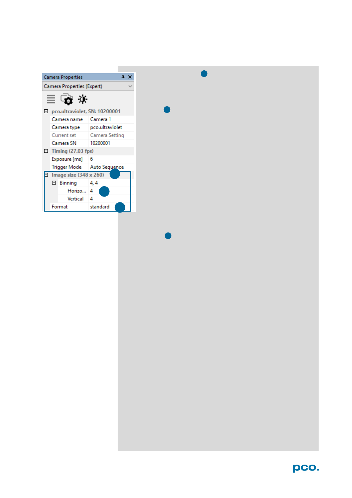
6.3.2 IMAGE SIZE
The actual image size 1 is displayed here. Binning or Region
of Interest settings affect the image size and are applied
automatically.
Binning
Binning combines adjacent pixels (in either the horizontal or /
and vertical direction) to form super pixels. It increases the light
signal of the resulting pixels and decreases the spatial
resolution of the whole recorded image.
Since the readout is done only once for all binned pixels, the
signal to noise ratio increases. Vertical binning increases the
readout speed (x2 vertical binning = double frame rate).
Available Binning Modes:
H1xV1, H1xV2, H1xV4, H2xV1, H2xV2, H2xV4, H4xV1, H4xV2,
H4xV4
Sensor Format
A sensor’s feature provides the option to either read out the standard
size of 1392 x 1040 pixels (effective pixels recommended by the
sensor manufacturer) or an alternative size of 800 x 600 pixel (center
mode).
17
Page 18

ttd: trigger acknowledge delay tid: intrinsic delay
t
itf
: interframing time
trigger
busy
exposure
t
t
id
t
td
t
exp1
t
t
t
1
24 MHz
t
td
+
tid
5.8 µs
t
exp
1 µs … 60 s
t
read
140 ms (@ full resolution)
t
itf
1 µs
1 2 3 2 4
6.3.3 SENSOR CONTROL
Sensor Control allows controlling of all sensor specific settings.
Double Image / Doubleshutter
This feature is widely used for particle image velocimetry (PIV)
measurements and is an standard feature of the pco.ultraviolet.
The first exposure time t
available range of the pco.ultraviolet camera. The second
exposure time t
the second exposure is exactly the readout time t
image. The interframing time t
between end of exposure #1 and start of exposure #2. Readout
times t
A1.3.
While recording in Double Shutter mode, Camware will
automatically split the view window and always shows both
images side by side.
Double Shutter timing
may be any exposure time of the
exp1
can not be directly adjusted. The length of
exp2
denotes the transition time
itf
and t
readA
are exactly the same. See also appendix
readB
of the first
readA
t
: exposure time 1st image t
exp1
: exposure time 2nd image t
t
exp2
18
exp2
itf
read A
: readout time 1st image
readA
: readout time 2nd image
readB
read B
Page 19

6. CAMWARE 4 SOFTWARE
3
4
Conversion Factor
The conversion factor defines how many charges (electrons),
generated by light in each pixel, are necessary to generate one count
(one intensity level) in the digital image. Therefore, the conversion
factor describes the gain when converting electrons into a digital
value.
The pco.ultraviolet has two conversion factors namely 0.8 e
-
1.4 e
/ count which both can be used in 1x1 (full resolution) and
higher binning modes. As mentioned in 6.3.2. binning is available for
the pco.ultraviolet. The usable extended fullwell-capacity rises in
binning mode from 14000 to 24000e
makes sense to keep 0.8 e
-
the high dynamic of 16384 grey steps is not usable.. In higher
1.4e
binning modes you can use both conversion factors: Having a
lowlight scene the 0.8 e
information content – in normal light scenes it makes sense to use
-
/count for full dynamic availability.
1.4e
-
/count; changing the conversion factor to
-
/count mode helps to spread the low image
-
. In 1x1 (full resolution) it
-
and
19
Page 20

1
2
3
4 5 1
2
2
3
4
5
6.3.4 RECORDING CONTROL
Recorder Mode
In Sequence mode recording stops upon reaching the number
of images allocated in RAM (See 6.2). In Ring Buffer mode the
camera will stop only by a stop command. In this mode the
RAM is a circular buffer and continuously overwritten, starting at
the first image..
Timestamp
A timestamp can be placed into the upper left corner of the
image. It can be either No stamp, Binary or Binary + ASCII.
The time resolution is 1 μs.
In binary mode the first 16 pixels will be filled with the time
stamp information (binary code). The numbers are coded in
BCD with one byte per pixel, which means that every pixel can
hold 2 digits. If the pixels have more resolution than 8 bits, then
the BCD digits are right bound adjusted and the upper bits are
zero. For further information please refer to the SDK.
In binary and ASCII mode text will be placed into the image
replacing the content of the image (271x 8 pixels).
Timestamp shows the end of exposure time.
Three different information is stamped onto the image: image
number of the, date and time .
Additionally to Timestamp the Image overlay function is
available, see chapter 6.4.
6.3.5 STATUS
Shows the current temperature level of the pco.ultraviolet
camera.
20
Page 21

6. CAMWARE 4 SOFTWARE
1 3 4
2
GPU Processing
Fast pco debayering:
Color Refine Filter not available
Noise Reduction
Denoise Adaptive: not available
Sharpen:
On: not available
1
2 3 4 1 3
1
2 3 4
4
2
6.3.6 CONVERT CONTROL DIALOG
Start the Convert Control Dialog with the Black/White Button
in Camera Properties.
Convert Control BW
The user can manipulate the display of the original 14 bit image
intensity values (x-axis) in the displayed 8 bit values (y-axis).
BW Settings (includes histogram of original
data)
It is possible to
data
Green sliders in histogram
left slider = Min controller (corresponds to
value 0 of the 8 bit display). Values below that
mark are set to 0, i.e. displayed as black.
right slider = Max controller (corresponds to
value 255). Values above that mark are set to
255, i.e. displayed as white.
hide the histogram of original
and to switch tab/histogram .
The values in-between are converted into a value between 0 and 255
according to Contrast and Gamma settings. The small graph ,
reflects the calculation.
Proc. Config (Process configuration)
Due to proprietary high-end algorithms used
for these image processing features, no
detailed description is given here.
On: Switch on in order to significantly reduce
processing time (increases refresh rate of the
live image.
not available
NLM: Non local means algorithm
Converted Hist
This tab shows you the histogram of
converted data.
Other functions (Saturation, Vibrancy, Col.Temp, Tint) are inactive
for monochrome cameras
21
Page 22

6
7
1
2 2 5
6 57
1
NOTE
3
4
3
4
6.4 IMAGE OVERLAY
Open Image Overlay: these two buttons allow easy switch between
Camera Properties and Image Overlay.
If not available, please see 6.9.5 View Menu to activate this menu.
This function enables an individually configurable image overlay
allowing to display information within the images.
Many different options are available by clicking Add item to…
Also the Appearance is configurable:
Font, Text color, Text opacity, Background color, Background
opacity and horizontal or vertical orientation.
Camera image number and Camware Image Number are two
different count methods:
Camera image number: the image numbers are incremented
continuously. When recording in Ring Buffer mode, the image
numbers exceed the number of images stored in the RAM memory
of the computer since images are overwritten when the memory is
full, starting with the first image in loop.
Camware image number: the software displays the image numbers
according to the number of images being recorded (starting with
image 1).
A preview of the image overlay is shown.
Each item can be moved upwards, downwards or deleted by clicking
on …
By drag & drop the Image Overlay can be moved easily to your
favorite position within an image.
To activate image overlay right-click in the image
window and activate Show Image Overlay.
This function does not overwrite image data.
22
Page 23

6. CAMWARE 4 SOFTWARE
1
2
1
2
6.5 RECORDER TOOLS
Recorder Tools provides Record and Play function, Play Settings
and Record Settings.
It can be found on the right lower side of Camware or, if closed,
activated by View Menu (see chapter 6.9.5)
Record
Play Settings
Start / Stop record: with Record Button.
or press enter in the View window to Start / Stop recording.
Record: in record state Camware software is highlighted in red.
Exposure time may be changed during recording. See 6.3
Camera Properties.
Software Trigger Mode: after record is started an arrow
pointing downwards appears, which releases a single trigger
(see 6.3.1).
Play Speed: selectable play speed from x1 to x256 or from 1
fps to 16 fps. E.g. in mode x1 a recording with 1000 fps is
played with 25 fps.
1 fps means that only one frame per second is played.
Play Mode: selectable play mode of the recorder (continuous or
single time (re)play).
Play Direction: selectable direction of record play (forward or
backward)
Record Settings
Averaging: if in the dropdown list a value not equal to x1 is selected,
the corresponding number of images is averaged in the buffer,
reducing the statistically independent noise.
IIR Lowpass: another option to reduce the noise is the activation of
the Infinite impulse response IIR lowpass filter. This filter takes
90% of the previous image and 10% of the new image to create
images with clearly reduced noise.
Image (actual) = Image (act - 1) * 0.9 + Image (new) * 0.1
23
Page 24

3
1
3
1
2
3
2
3
Reminder dialog: If you have already made a recording but did not
save it, Camware will ask you to save the record before starting a
new one.
Extended Recorder can be activated (see 6.9.5)
Functions:
- Start & Stop record / Stop record / Replay
- First image (jump to first image) / Back fast (jump backward) /
Back (jump one image backward)
- Forward (jump one image forward) / Forward fast (jump forward) /
Last image (jump to last image in record)
Recording with multiple cameras
With all cameras activated recording is started simultaneously
for all cameras.
Recorder will use Recorder mode settings (Sequence or Ring
Buffer) of the active camera for all cameras (see 6.3.4)
For single camera recording, deactivate cameras by removing
the check mark from the box.
24
Page 25
6. CAMWARE 4 SOFTWARE
1 2 4
5
1
2
3 3 6
4 5 6
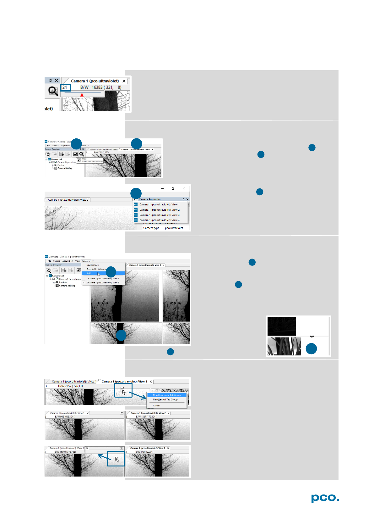
6.6 VIEW WINDOW
Fast-scroll through images
If you have recorded at least 50 images, you can scroll through the
images quickly. To do this, hold down the left mouse button on the
image number. Additionally you can enter the desired image
number directly into the number field.
More View Windows
It is possible to open more view windows from one
camera: just click on open new view window 1 and
Camware will create a new one 2 .
Even when multiple view windows (or from multiple
cameras) are open, the same image number is always
shown in all of the view windows.
A dropdown menu helps to select a view
window. If there are more view windows than
can be displayed on the desktop, you may
select individual view windows.
Split View Window
The view window can be split. Choose
Window → Split 4 and a split cross will be
shown. The size of splitted window elements is
easily adjusted by grabbing and dragging the
dividing lines 5 .
The main reason for this function is to view four
sections of the image in one view. Choose the
Zoom± function to zoom in the image (first turn
off Stretched View)
(See 6.9.8)
To undo the split
double click on the
separator line (once
the symbol 6 becomes visible).
Two Tabs side by side or on top of each other
To view two tabs side by side or arranged one
above the other just drag a tab and then
Camware will ask wether you want to create a
new horizontal or vertical tab group. Undo this
very easily by draging the tab back to its former
position.
This also applies for view windows of several
cameras.
25
Page 26

1
2 2 1
6.7 RECORDER (IMAGES)
When recording is done, small preview images (thumbnails) are built
and displayed automatically in the Recorder docking window. This
will take some time depending on the performance of your computer
system and of the interface used.
If you click (left mouse button) within the upper scale bar 1 , you can
adjust the number of images which are shown by moving the mouse
left or right. Minimum is 20 and maximum is half of the recorded
images in this scale.
Quick scrolling: you can quickly scroll through the thumbnails by
dragging the orange bar with the mouse or by mouse wheel while
the cursor is over the image number bar.
While quick scrolling, the Preview window will display the active
image sequence. This allows to quickly scroll through the image
sequence displaying the images in the Preview window forwards or
backwards. The View window will not actively show live images
during quick scrolling (only in normal scrolling speed by mousewheel).
Clicking on a thumbnail image it will be shown in the view window.
Scroll via mouse wheel through the thumbnails.
The upper blue bar correlates to the number of displayed
thumbnails. The lower blue bar shows the range of the upper scale in
relation to the whole record.
The second scale shows the total number of recorded images. It
allows fast scrolling through the images 2 .
26
Page 27
6. CAMWARE 4 SOFTWARE
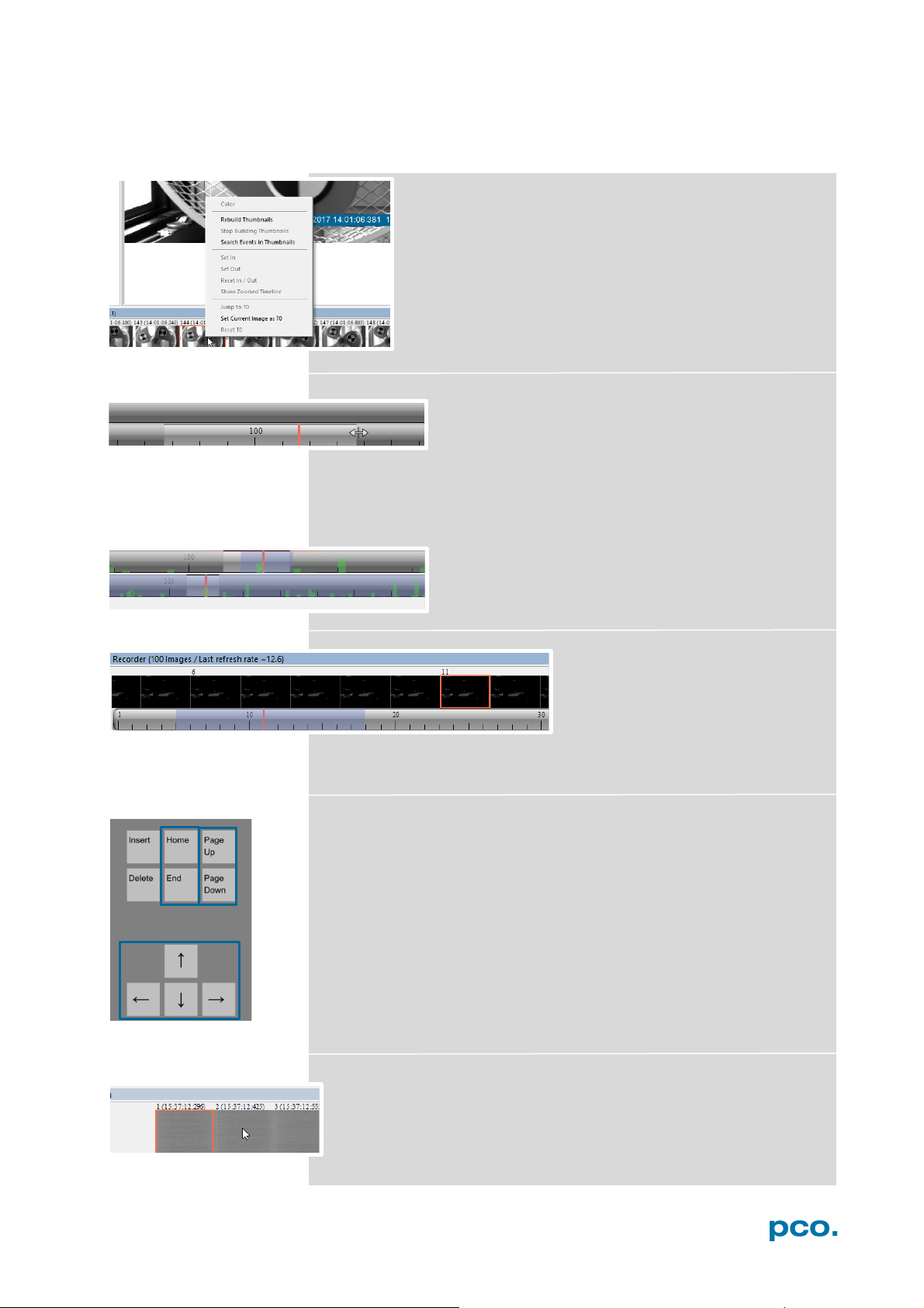
Right-click menu (click on thumbnails)
Allows to rebuild all thumbnails and to search for events.
Furthermore Set In / Out enables to set values for a
sequence to set values for a sequence, which can be
played via play button. Reset In / Out discards these
settings.
Set In / Out is active: if you save/export images, only the
selected images are saved/exported (see 6.7.2).
The light gray area in the upper scale shows an In-
Out example area. Define easily a new area: just
right-click on the start and end frame in one of the
scales. The In image must be left side to the red bar, the Out image
on its right side.
Adjust the In / Out area by holding down the left mouse button and
sliding the borders.
Search Events in Thumbnails: detected events are
displayed as green bars.
Too dark or bright thumbnails
If thumbnails are too dark or too
bright, right-click in view window
(see 6.9.8) and select Auto Range
Peak or Auto Range Crop. Then
right-click on a thumbnail image and select Rebuild Thumbnails.
Now the thumbnail images should comply with the view window.
Use your keyboard to scroll through the Recorder Images
Page up / down keys: 10 Images up or down.
Arrow keys: quick scrolling through the images.
Advantage: fluent video playback in the View window (forwards or
backwards).
Home/Pos1 key: first image.
End key: last image.
Adddtional short-cuts:
While mouse is in the thumbnail area in Recorder (Images):
Press CTRL + left mouse button to jump to the first image
Press CTRL + right mouse button to jump to the last image
27
Page 28

4 5 6
7 8 9 101 2 3
11
No.
Function
Description
Camera name
Name
Auto Save
Off , Unconfigured (red), OK (green)
Type
Camera type and serial number
Status
Ready or Recording
Frame Rate
Currently selected frame rate
Resolution
Resolution in pixels
Exposure Time
Selected exposure time
Number of Images
Number of images to be recorded
T0 Position
Not available for pco.ultraviolet
Ext. Sync. State
Not available for pco.ultraviolet
1
11 3 4
5 6 7
8 9 10
2
6.8 SETTINGS OVERVIEW
Settings overview shows the most important parameters of your
camera(s) at a glance. If you have more than one camera connected,
each camera and its parameters are listed.
The parameters can only be changed under 6.3 Camera Properties.
It is possible to easily switch between the Recorder (Images) section
and the Settings Overview.
Green background: Images are in memory
28
Page 29

6. CAMWARE 4 SOFTWARE
6.8.1 AUTO SAVE
Auto Save makes it easy to save recorded images or sequences.
There is no need to save each image/sequence separately from each
connected camera. Therefore this function is very useful if you use
more than one camera. Once configured Auto Save allows acquiring
and saving many images/sequences of your experiment as desired.
This function stores RAW (e.g. TIFF) and Export (e.g. AVI, JPG) files.
Standard file save see File Menu 6.9.2.
Explanations will be displayed in the Info Text window at the bottom
of the menu.
Enable Auto Save by clicking on the check box.
The text will change to Unconfigured! (red
background).
Right-click on the Unconfigured! field and click on
Configure ‘Auto Save’.The Auto Save Options
dialog will be displayed.
First, configure the General Auto Save Settings - Global
Auto Save Mode: two different modes are available, Save manually
and Save unattendedly.
Save manually mode stores RAW images and exports them after a
recording session by pressing ALT + D keys. This allows to cut an
image sequence in the Recorder Toolbar before saving.
Save unattendedly mode downloads all RAW images and exports
the complete image sequences of all cameras immediately after an
active recording is stopped.
Select Output:
Off – Auto Save is deactivated
Save RAW – only 16 bit RAW files are stored (b16,
pcoraw, MultiTif-File, Tiff
Export – only compressed files are stored (BMP,
JPG, Tiff, AVI, MPEG, WMV)
Save RAW and Export – RAW and compressed
files are stored simultaneously
Common Folder: main folder for stored files
RAW and Export file Type: select the type of RAW
and compressed file
Export Color Image: select if you want to export
color images (only for color cameras)
Apply Automatic File Naming: if set to yes, your
stored files are automatically named by Camware
according to your automatic file name settings.
29
Page 30
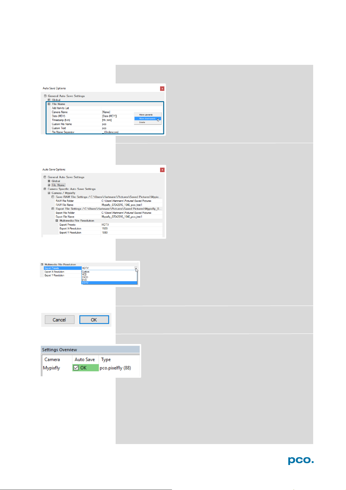
General Auto Save Settings – File name
Set your file name individually by adding or deleting
items. Position these elements as needed.
Camera Specific Auto Save Settings:
Configure camera specific settings for each
connected camera.
Save RAW File Settings: set RAW File Folder and
RAW File Name (if not set to automatic file
naming).
Export File Settings: set Export File Folder and
Export File Name (if not set to automatic file
naming).
Multimedia File Resolution: set predefined video export
resolution or enter a Custom x- and y-resolution.
It makes sense to set the resolution to the actual camera's
resolution.
Finish the configuration by clicking OK.
After configuration is finished, Auto Save status will be set to
OK (green background).
30
Page 31

6. CAMWARE 4 SOFTWARE
6.9 CAMWARE MENU TABS & FEATURES
This chapter describes the Camware Demo Mode and the Camware
Tabs: File, Camera, Acquisition, View and Window. Furthermore the
right-click menu and some additional features are listed.
6.9.1 DEMO MODE
Upon start Camware, it automatically recognizes the camera
type of the connected and running cameras.
Camware starts in Demo Mode, if your camera is switched
off or no camera is connected
In this mode all image processing features are available,
but all camera settings are deactivated. Just tell Camware
the type of image you want to open. For that purpose, the
Demo Mode Setup window opens and asks for the
corresponding input.
Need Help? Having troubles to run the camera, this window
will pop up. See instruction in appendix A3.
Resolution
The drop down list displays the existing image sensor spatial
resolutions of all PCO camera systems. Please select the specific
resolution and bit depth of the images to be opened. If Double
Shutter images have been recorded and should be opened, Double
Shutter Mode should be ticked.
Color
With the radio buttons, the user can specify whether the image type
is monochrome (b/w) or color.
Alignment
These two radio buttons adjust whether MSB (most significant bit)
aligned (upper) or LSB (least significant bit) aligned (lower) images
have been stored.
Infotext
The Infotext is automatically shown in Camware
when a stored image sequence is opened.
The Camera Properties settings, storing location
and Record date are listed in this file.
Infotext can be activated in the View Menu 6.9.5 at
any time.
31
Page 32
NOTE
e aware of the
different storage
abilities of the
formats, for example
the bitmap
8bit values to be
stored and therefore
16 bit image is
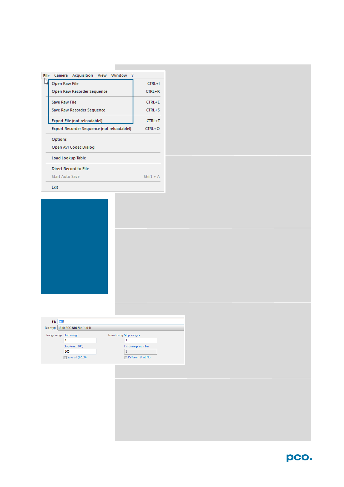
6.9.2 FILE MENU
B
*.bmp format only allows for
the image content of a
reduced, if stored as
bitmap.
Open RAW File (single image only)
This command should be used to import a single
image into the currently active image window. Only
files with the extension and format of *.b16 (=PCO
proprietary binary image format) and *.tif (16 bit
TIFF image format) can be imported. If the recorder
is enabled, each imported image will be transferred
to the buffer shown in the picture number. The
image itself will be fitted to the current image size.
If the recorder is disabled, the current image size
will be set to the parameters of the imported
image.
Open RAW Recorder Sequence (image sequence
from one camera)
This command is used to import a sequence of
images. If more than one camera is connected and
an image window is currently open, the sequence
will be loaded to the active window. If no image
window is open, the images will be loaded to camera #1. This
command opens the Open file dialog box. Only files with the
extension and the format of *.b16, *.pcoraw, *.tif and multi tif can be
imported.
Save RAW File (single image only)
This command should be used to save the image displayed in the
active window. The command opens the Save file dialog box. The
image file can be saved in 16bit *.b16 and *.tif format. If more than
one camera is connected, all current images may be saved by
selecting Export all images in the Save file dialog box. This feature
allows to save one image of each active camera within one process
step (it is not necessary to repeat the save process for each camera).
The Save command will not be available, if no image window is open.
For Auto File Save see 6.8.1
Save RAW Recorder Sequence (image sequence from one camera)
This command should be used to save or
export image sequences. If more than one
camera is connected and an image window
is currently open, the record of the active
window will be saved. The command opens
the Save recorder file dialog box. It is
possible to select the number of saved
images, to step images and to choose the
first image number. For Auto File Save see 6.8.1
Export File (not reloadable!)
Use this command to export the image of the active image window.
This command will open the Export Image dialog box. Files with the
extensions fts, tif, bmp, asc, jpg, and jp2 can be exported. This item
will not be visible, if no image window is open. For Auto File Save
see 6.8.1
32
Page 33

6. CAMWARE 4 SOFTWARE
Export Recorder Sequence (not reloadable!)
Use this command to export a sequence of
images. If more than one camera is connected and
an image window is currently open, the record of
the window which has got the input focus will be
saved. If no image window is open the Export
Recorder Sequence menu does not appear. This
command opens the Export recorder box. Files
with the extensions fts, tif, bmp, asc, avi, mpg, jpg,
jp2, and wmv can be exported (see Appendix A3).
For Auto File Save see 6.8.1
Options
Single File Properties
Single tif file 16 bit alignment: upper / lower
ASCII File Separator: select a separator for
the values in the ASCII file. Select: tab, space,
semicolon, colon, comma, hyphen, slash,
backslash.
Binary pgm file: set the format of the pgm
(portable gray map) file. Select: yes, no.
Jpeg2000 image quality: set compression
from 20 to 100%.
Jpeg image quality: set compression from 20
to 100%.
Binary ppm file: set format of the ppm
(portable pixmap) file. Select: yes, no
RAW 16bit RGB tif file: save raw tif without
color balance. Select: yes, no.
Use cache file: Caches image data on disc for
a camera with camera internal memory.
Select: yes, no (not available for
pco.ultraviolet)
General File Properties
FIFO buffer size: set the FIFO buffer size in number of images. This
helps to avoid gaps during file write delays. Usually this is set to 150.
Preserve last record: preserve current recorded images. When set,
the user will be asked whether to really start a new record or to close.
View Properties:
Crosshair color: set the color for crosshair, save ROI and line tool.
Crosshair length: set the crosshair length in pixel.
Activate crosshair: see chapter 6.9.8
33
Page 34

Open AVI Codec Dialog
Settings in Auto File Save affect stored video
sequences stored video sequences.
You only need to set this option, if you use Auto File
Save see 6.8.1
Select the (compression) codec you want to use for
your stored sequences. All installed codecs are listed
here.
Load lookup Table (for monochrome cameras)
This feature assigns pseudo colors (lookup tables) to a monochrome
image. Either use one of the four predefined or create your own. The
result is shown in the color view window.
Direct Record to File
This command presets a certain number of images to be stored. If
the camera captures images faster than the computer can save to
disk, you will lose images. Displaying of the images doesn't interfere
with the record process.
Start Auto Save
Only available if Auto Save is activated, see 6.8.1
Exit
This command exits the program and closes all channel dialog
windows. Window positions, settings and sizes are stored in the
windows registry and will be loaded again at next start-up.
6.9.3 CAMERA MENU
Camera Control
Use this command to open the camera control window.
Close
Disconnects camera and switches Camware to Demo Mode. In case
of multiple cameras, all cameras have to be closed individually for
Camware to switch to Demo Mode.
Rescan Disconnects and reconnects all cameras.
Setup (not available for pco.ultraviolet)
34
Page 35

6. CAMWARE 4 SOFTWARE
6.9.4 ACQUISITION MENU
Live Preview
The Live Preview is useful for fast and easy adjusting and
focusing of the camera. The active window will be updated.
To see another window, simply click on the window. This
option is not available in Double Shutter mode.
Acquire Picture
Active if Recorder Mode is set to Soft Trigger, see 6.3.1
Acquire Sequence
Starts recording images into the computer’s RAM according to
Trigger Mode selection (see 6.3.1). During recording, all camera
controls are locked.
Rec. Memory Settings
Sets the number of images recorded in one sequence. The
maximum is defined by pre-established RAM size.
6.9.5 VIEW MENU
B/W or Color Window
Command to open a new display window.
Multi Window
View the images of all active cameras in
consecutive order in one window. This
function provides an easy comparability of the
views of different cameras.
Use the same ROI and timing settings for all
cameras.
Only available when using more than one camera. After a complete
sequence is recorded (sequence mode) or Ring Buffer is full for the
first time (Ring Buffer mode).
Convert Control
See 6.3.6
35
Page 36
2 3 5 1 4
1
2
3 4 5
6
6
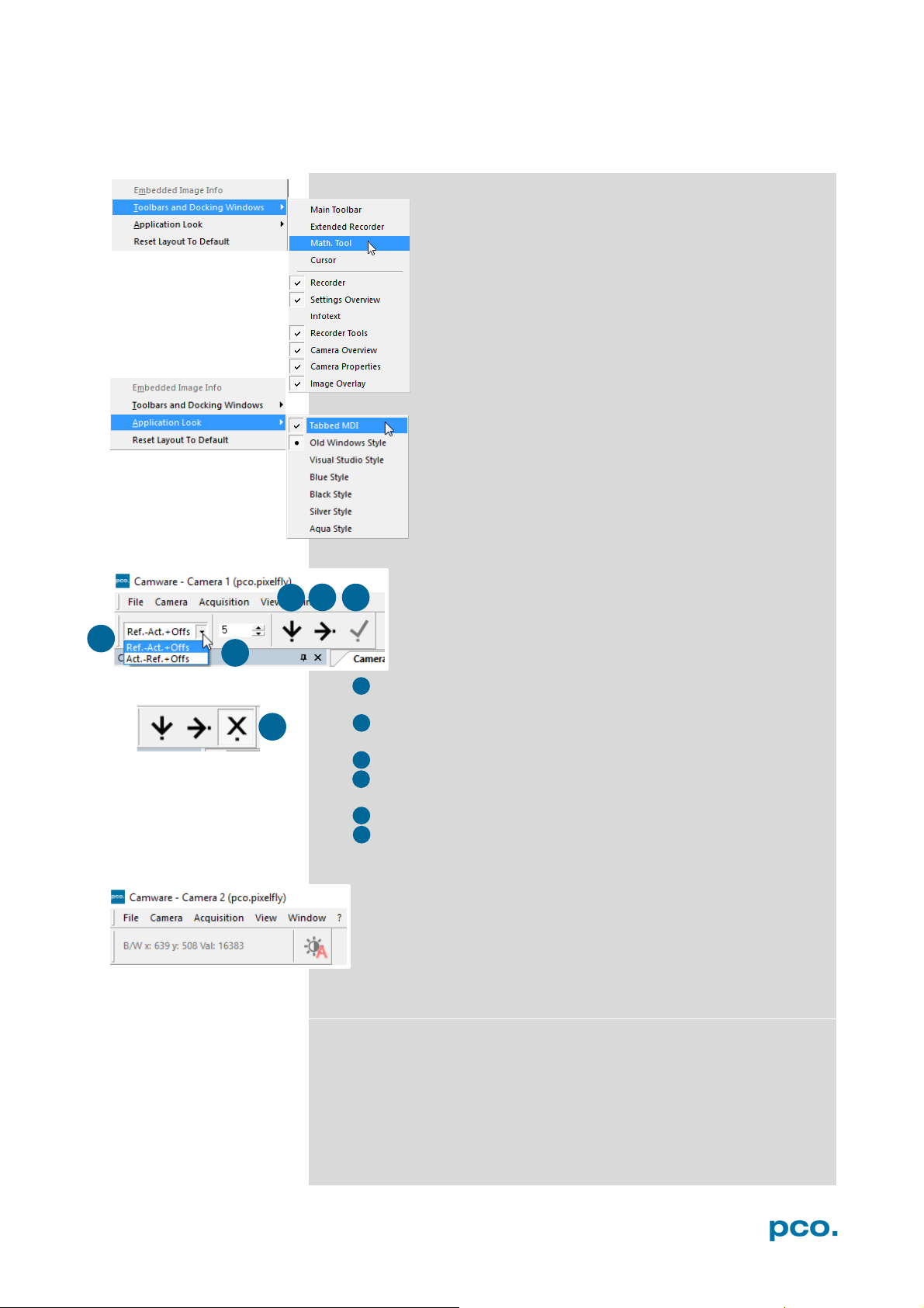
Toolbars and Docking Windows
Standard toolbars of Camware 4 are Recorder/
Recorder Tools / Camera Overview / Camera Properties
and Image Overlay. Additional Toolbars known from
Camware 3.x are displayable, but not essentially
needed: Main Toolbar / Extended Recorder / Cursor.
For function Infotext see 6.9.1.
Application Look
The Style and Look of Camware can be customized;
many different style sheets are selectable. The Tabbed
MDI function (un)docks the view windows.
Math Tools
With the math window you have the ability to calculate the
difference between a reference image and the actual
image. Activating math every new image acquired will be
subtracted from the reference image or vice versa:
• Reference (image) – Actual (image) + Offset or
Actual (image) – Reference (image) +Offset
• a reference picture will be acquired and copied to reference
buffer
• last acquired image will be copied to reference buffer
• add offset to avoid negative values, which would not be
visible
• enable math function
• disable math function
Cursor
Shows position of mouse cursor.
Example: B/W (black/white camera) x-axis: 639; y-axis: 508;
Value: 16383 counts
Reset layout to default
This resets all your customized changes and restores the default
layout.
36
Page 37
6. CAMWARE 4 SOFTWARE
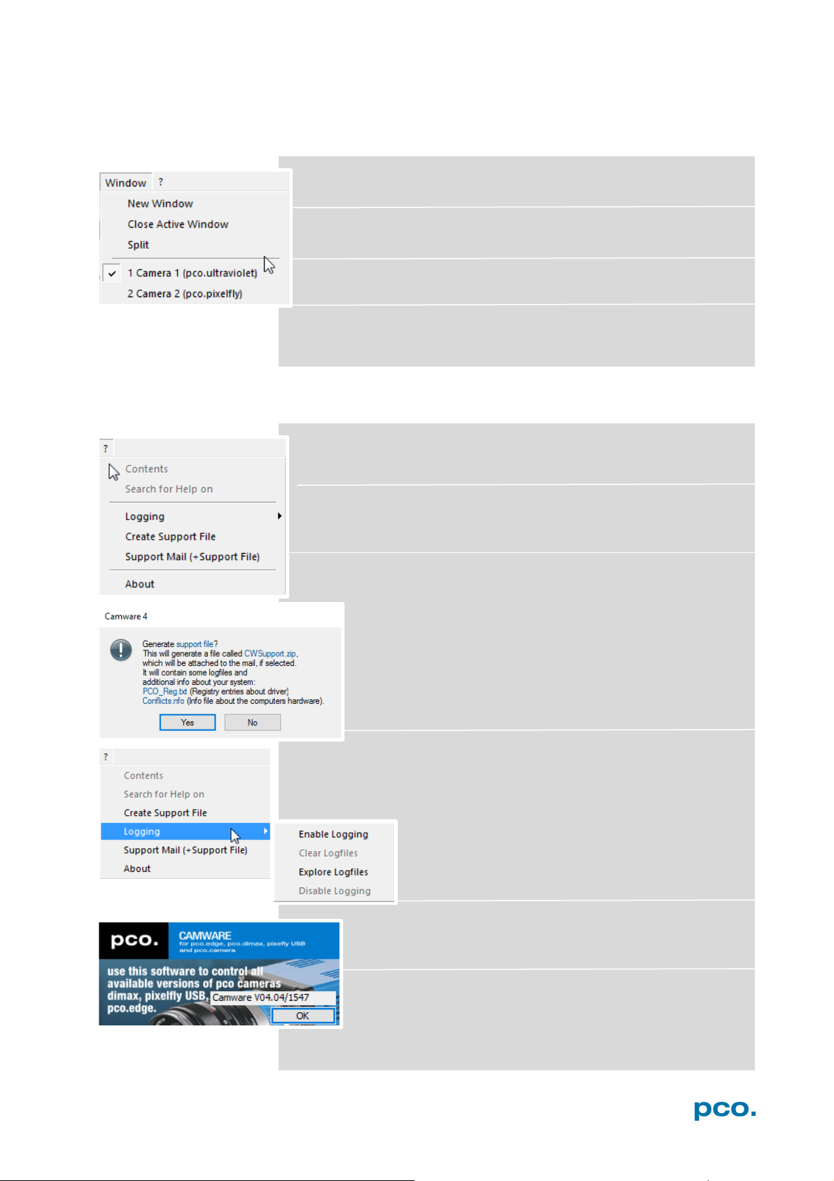
6.9.6 WINDOW MENU
New Window
Opens a new one.
Close Active Window
Closes the active one.
Split
The view window will be split in four quarters.
Camera overview
Shows all connected cameras, e.g. Camera 1 (pco.ultraviolet)
6.9.7 HELP MENU
Contents
Opens the main page of the program help.
Search for Help on
Opens an index list for help.
Create Support File
Press YES to activate the Camware log files, reboot
Camware and your pco.ultraviolet. With activated log files it
is possible to create a support file. Send it to the PCO
support (see A3.3).
Logging
Enable Logging: Activates Camware log files (this cuts down
camera’s performance)
Clear Logfiles (only visible if logging is enabled):
erases all actual log files
Explore Logfiles: opens windows explorer
Disable Logging (only visible if logging is enabled):
disables logging
Support Mail
Opens your email-program and the created support file will
be added automatically as attachment.
About Camware
This window shows program information.
37
Page 38
1
2
1
2
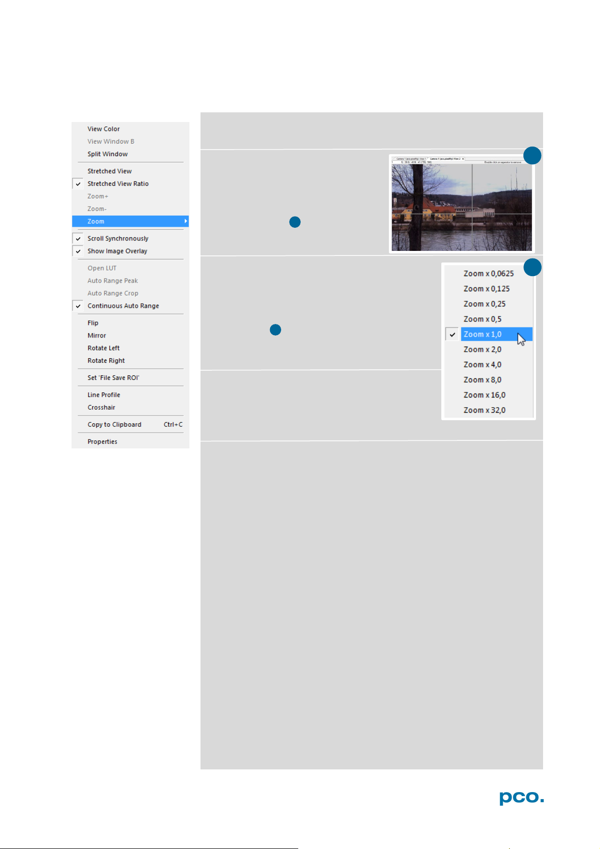
6.9.8 VIEW WINDOW MENU
All functions of the View window menu are explained briefly.
Right-click in the View window to open this menu.
View Color: color window.
View Window B: Double Shutter
activation switches to window B
window B (second image).
Split window: splits the View
window in four parts. Double click
on separator to undo.
Stretched View: image will be fitted into the
display window.
Stretched View Ratio: aspect ratio is
maintained.
Zoom +/-: image zoom (only available if
Stretched View is deactivated).
Zoom set the zoom factor (from 0.0625 to 32).
Scroll Synchronously: scroll synchronously
through all open image windows (only available
if Stretched View is deactivated).
Show Image Overlay: activates the overlay see 6.4
Open LUT: opens look-up table file for false-color assignment.
Auto Range Peak: searches for the minimum and maximum 14 bit
intensity values of the image. Given these numbers the converter
scales the 8 bit display (256) within these two values.
Auto Range Crop: sets the converter to ignore the extreme intensity
values of the image and scales the display in a smaller range. Thus
dark or bright light spots, reflections, etc. are cut off.
Continuous Auto Range: (Crop): this option enables the automatic
min/max function (Auto Range Crop) during record and replay.
38
Page 39
6. CAMWARE 4 SOFTWARE
Flip/Mirror: image will be flipped or mirrored.
Rotate Left/Right: rotates the image in steps of 90°.
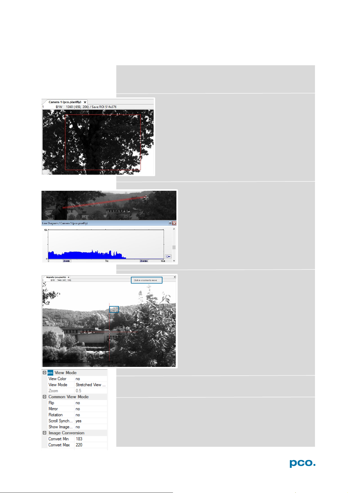
Set ‘File Save ROI’: if you want to save just a part of
the recorded image (region of interest), it is possible to
draw a rectangle with the mouse. This rectangle is valid
for all recorded images and can be dragged at its
edges.
Line Tool: point the mouse where the line
should start and left-click. Move the mouse to
the desired line end and left click again. The
line may be stretched, shrunk or moved by
grasping its end point. A Line Diagram opens.
The graph in the length of the line (units: pixel)
is displayed showing the intensity values of the
pixels along the red line.
Crosshair: activates a centered crosshair. Size
and color are selectable see chapter 6.9.2 →
Options.
To move the crosshair drag it by mouse, just
drag it by mouse. Reset it to center position by
double-click into the center of the crosshair.
Copy to Clipboard: will copy the actual image to clipboard.
Properties: shows the current settings for View Mode / Common
View Mode and Image Conversion.
39
Page 40
1
2
1
2
6.9.9 ADDITIONAL FEATURES
White Balance by Mouse
Change white balance by mouse: press CTRL (Strg) and shift button
simultaneously and select a white or gray area within the image by
dragging a rectangle while holding the left mouse button. The pixel
values within the coordinates of the selection rectangle are used for
calculating a new white balance.
Setting Contrast Area by Mouse
Control the minimum and maximum values used for the conversion
from 14 bit to 8 bit with the mouse. Move the mouse cursor into a
region which should be shown with maximum contrast. Press the
shift and the left mouse button. Hold down the mouse button while
changing the selection rectangle's size by moving the mouse. After
releasing the mouse button the coordinates of the selection rectangle
act as a border for calculating the minimum and maximum values.
Short Cut List
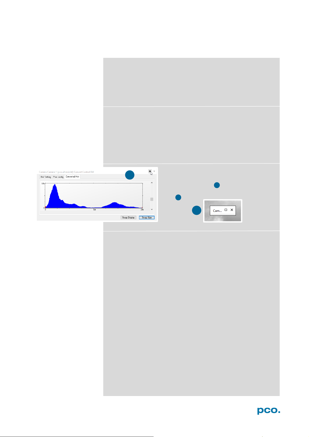
Fold Up Window
The Convert Control windows can be
minimized / folded up . Just move the pointer
over the bar and the window will unfold
again .
• Start / Stop record: ENTER
• Acquire Picture: SPACE (Soft Trigger mode)
• Acquire Sequence: STRG + A
• Auto Save: ALT + D
• Export File: STRG + T
• Export Recorder Sequence: STRG + O
• Open Raw File: STRG + I
• Open Raw Recorder Sequence: STRG + R
• Save Raw File: STRG + E
• Save Raw Recorder Sequence: STRG + S
40
Page 41

APPENDIX
APPENDIX
A1 TECHNICAL DATA 42
A1.1 DATA SHEET 42
A1.2 QE CURVE 43
A1.3 TRIGGER INTERFACE 43
A1.4 MECHANICAL DIMENSIONS 44
A1.5 NO INPUT WINDOW 44
A1.6 REVERSE WITH CAPTION 45
A2 IMAGE FILE FORMATS 46
A3 CUSTOMER SERVICE 48
A3.1 SERVICE 48
A3.2 MAINTENANCE 48
A3.3 TROUBLE SHOOTING 49
A3.4 RECYCLING 50
A4 INDEX 51
ABOUT PCO 52
41
Page 42

image sensor
type of sensor
ICX 407BLA interline CCD
resolution (h x v)
1392 x 1040 pixel (normal = full resolution)
800 x 600 (centered)
pixel size (h x v)
4.65 µm x 4.65 µm
sensor format / diagonal
1/2” / 8 mm
shutter mode
Global (snapshot)
MTF
107 lp/mm (theoretical)
fullwell capacity
14000 e-
24000 e- (binning)
readout noise
dynamic range
1750 : 1 (65 dB)
3000 : 1 (69.5 dB) binning
quantum efficiency
40 % @ 193 nm
spectral range
190 nm .. 1100 nm
dark current
1 e-/pixel/s @23°C
DSNU
2 e- rms
PRNU
< 1%
camera
frame rate
7.3 fps (normal = full resolution)
11.7 fps (centered 800 x 600)
exposure / shutter time
1 µs .. 60 s
dynamic range A/D
14 bit
A/D conversion factor
pixel scan rate
12 MHz
binning (h x v)
1 x 1 .. 4 x 4
non linearity
< 1 %
smear
< 0.005 %
anti-blooming factor
> 200 (standard 100 ms exposure)
interframing time
< 1 µs (optional)
trigger input signals
Software / TTL level
trigger output signals
3.3 V LVTTL level
data interface
USB 2.0
general
power supply
9 .. 28 VDC (12 VDC typ.)
power consumption
< 3 W
weight
0.35 kg
operating temperature
+10°C .. +35°C
operating humidity range
10% .. 80% (non-condensing)
storing temperature range
-20°C .. +70°C
optical interface
C-mount
CE / FCC certified
yes
A1 TECHNICAL DATA
A1.1 DATA SHEET
7 - 9 e- rms @ 12 MHz (typical)
0.8 e- / count
1.4 e- / count
Subject to change, please refer to current data sheet available on our website.
42
Page 43
A1 TECHNICAL DATA
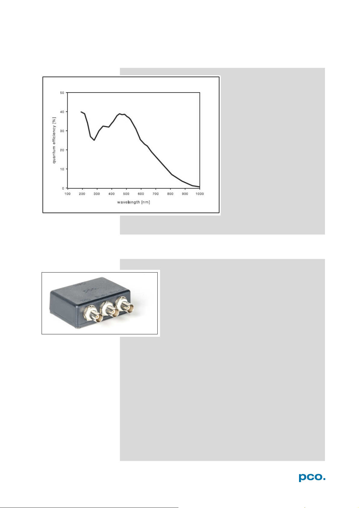
A1.2 QE CURVE
Peak: 40% @ 193 nm
Spectral range: 190 to 1100 nm
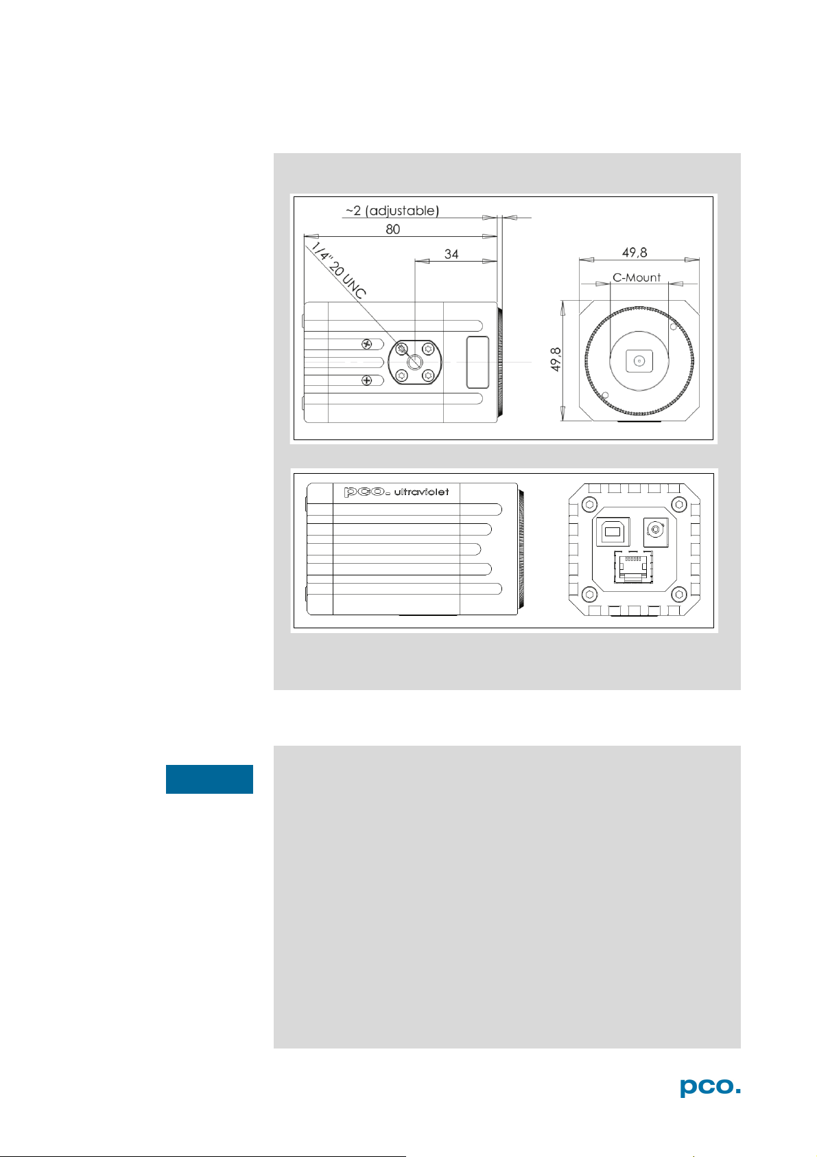
A1.3 TRIGGER INTERFACE
What
Connect the trigger interface to the RJ11-Connector of
your camera. It is equipped with three BNC outputs
(Trigger / Busy / Exposure). The trigger interface is just
a connection adapter from RJ 11 to BNC without any
active electronics.
For more information confirming trigger modes see A1.3
and 6.3.1.
43
Page 44
NOTICE
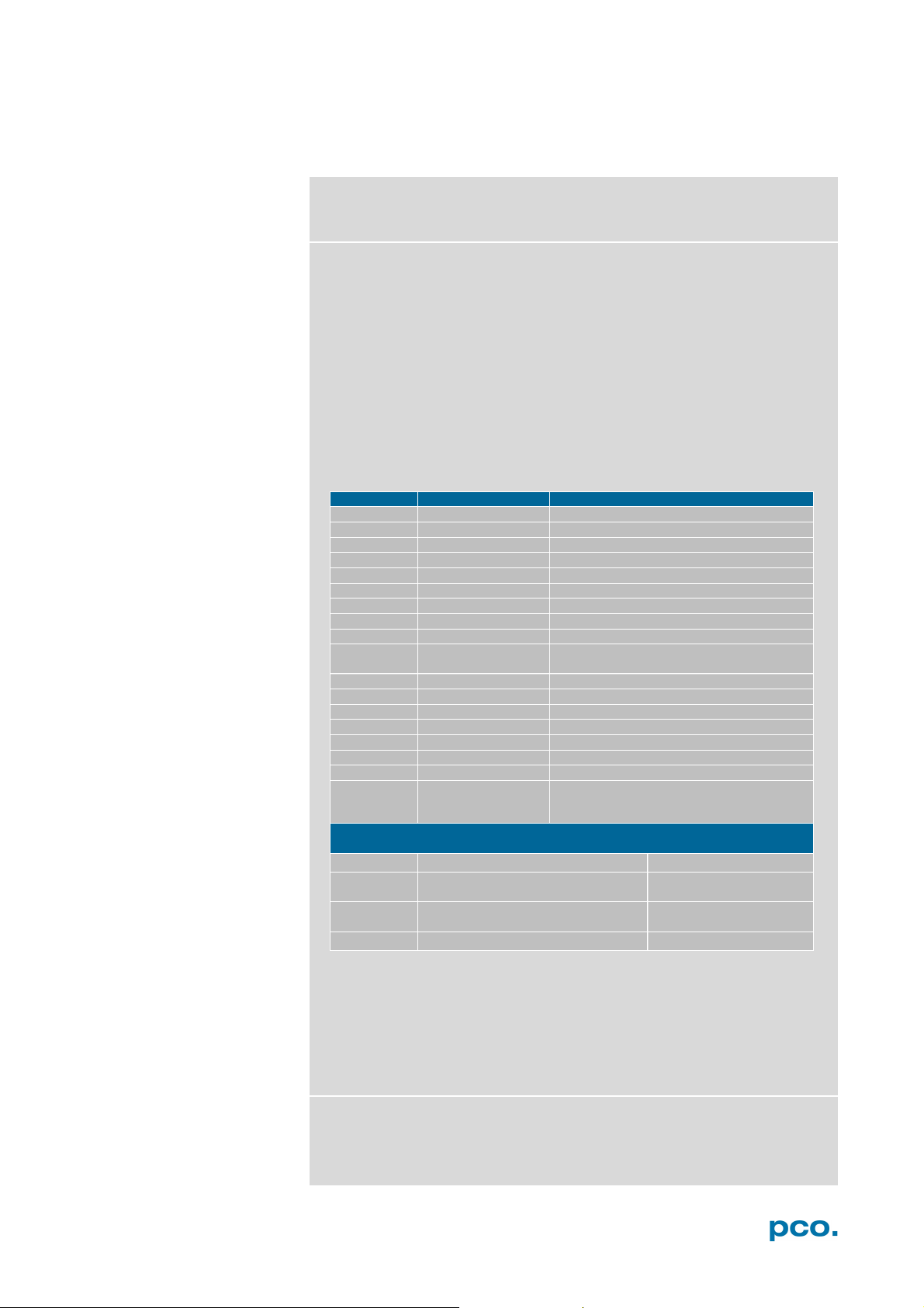
A1.4 MECHANICAL DIMENSIONS
All dimensions given in millimeter.
C-Mount flange focal distance: 17,52 mm
A1.5 NO INPUT WINDOW
The pco.ultraviolet does not have an input window to protect the
sensor.
If the lens is removed you have direct access to the sensor
The sensor surface itself has a glass, but this glass is very
Therefore, please be very careful when removing or changing
To clean the sensor surface only use commercially available can of
compressed air or contact your local PCO distributor for further
cleaning instructions.
surface.
sensitive and can be easily damaged (e.g. scratches).
optical components.
44
Page 45

A1 TECHNICAL DATA
Pin Description
1
GND
2
Exposure out (TTL 3V)
3
Busy out (TTL 3V)
4
not used
5
Trigger in (TTL 0…5V)
6
+12V (alternative power supply)
busy = TRUE / high
camera is recording or sensor
readout in progress
busy = FALSE / low
external trigger is ready to accept
exposure = TRUE / high
exposure of image sensor
1 2 3
1 2 3
Pin 1
A1.6 REAR PANEL
USB 2.0 plug
Power socket :
Input: 9…28V; max. 3W
RJ 11 connector
Pinout of RJ11 connector
Pin Position
Timing &
In Auto Sequence trigger mode the busy signal is always set to
TRUE, while the exposure signal indicates the real exposure of the
image sensor.
In External Exp. Start trigger mode the camera is ready to accept a
new trigger signal on PIN #5 (trigger) when the busy signal is set to
FALSE. After a successful trigger event the busy signal stays TRUE
until the exposure is finished and the image is completely read out.
Signals
45
Page 46
Parameter
Function
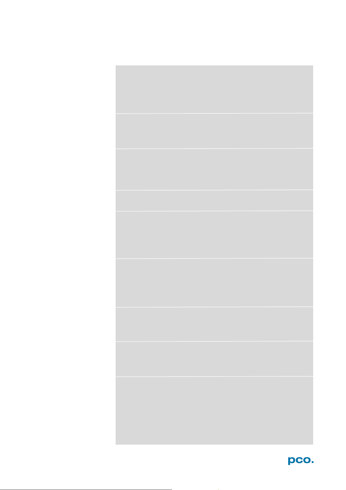
1
PCO-
the first 4 byte are the characters PCO-
2
file size
file size in byte
3
header length
header size + comment filed in byte
4
image width
image width in pixel
5
image height
image height in pixel
6
extended header
-1 (true), extended header follows
7
color mode
0 = black/with camera, 1 = color camera
8
b/w min
black/white LUT-setting, minimum value
9
b/w max
black/white LUT-setting, maximum value
10
b/w linlog
black/white LUT-setting,
0 = linear , 1 = lo garithmic
11
red min
red LUT-setting, minimum value
12
red max
red LUT-setting, maxim um value
13
green min
green LUT-setting, minimum value
14
green max
green LUT-setting, maximum value
15
blue min
blue LUT-setting, minimum value
16
blue max
blue LUT-setting, maximum value
17
color linlog
color LUT-setting, 0 = linear, 1 = logarithmic
18
Comment file in ASCII characters with variable length of 0…XX.
16 bit pixel data
line 1,
pixel 1
value of the firs t pixel
line 1,
pixel 2
value of the second pixel
…
…
A2 IMAGE FILE FORMATS
There are different file formats available for saving camera images
with Camware.
b16
The b16 16 bit format is similar to the bmp format. However, 16 bit
pixel values are used instead of 8 bit pixel values.
The file format consists either of a Basic Header (6 Long-parameter)
or an Extended Header (32 Long-parameter), the latter of which is
optionally for additional information. There might follow a variable
comment field (ASCII code). Finally, there is the actual data set that is
saved linearly (as in the case of BMP files).
With the exception of the first value, all parameters are Long Integers
(4 Byte). The first 6 parameters must always exist. The rest of the
parameters, as well as the comment field, are optional.
266
The length of the comme nt file must be documented in the header length field.
internal use
PCO recommends that all images should be saved first in the b16
or TIFF format. The advantage is to have the b16 or tiff images
available all the time. You will always have the maximum 16 bit
information. Note that not all image analysis programs can
accommodate 16 bit data. The 8 bit format saves only the information
displayed on the monitor screen. The 16 bit information will be lost
and cannot be recovered.
pcoraw
This 16 bit PCO file format is based on the new BigTIFF format, thus
allowing for file size > 4GB. A new PCO proprietary compression
scheme is added in case it is necessary
46
Page 47
A2 IMAGE FILE FORMATS
Standard File Formats
TIFF
Tag Image File Format, version 6.0 and lower. There is a 16bit
monochrome and color image format.
BMP
Windows Bitmap Format, b/w or color 8 bit format-images, which
have been saved in BMP format can be loaded later only as 8 bit
images, i.e. part of the original information (16 bit) is lost.
FTS
Flexible Image Transport System, Version 3.1 is a 16 bit image
format. The NASA/Science Office of Standards and Technology
(NOST) defined it. Some programs use the FIT extension for this
format.
ASCII
16 bit format, some mathematical programs prefer ASCII data.
JPG
JPEG (named after the Joint Photographic Experts Group who
created the standard) is a commonly used method of lossy
compression for photographic images. The degree of compression
can be adjusted, allowing a selectable tradeoff between storage size
and image quality.
JP2
JPEG 2000 is a wavelet-based image compression standard and
coding system. It was created by the Joint Photographic Experts
Group committee in the year 2000 with the intention of superseding
their original discrete cosine transform-based JPEG standard
(created 1992).
AVI
Audio Video Interleave is a multimedia container format introduced by
Microsoft in November 1992 as part of its Video for Windows
technology.
MPG
MPEG-1, similar to JPEG, is a standard for lossy compression of
video and audio developed by the Moving Picture Experts Group
(MPEG).
WMV
Windows Media Video (WMV) is a compressed video compression
format for several proprietary codecs developed by Microsoft. The
original video format, known as WMV, was originally designed for
Internet streaming applications, as a competitor to RealVideo.
47
Page 48

NOTICE
CAUTION
NOTICE
NOTICE
NOTICE
NOTICE
A3 CUSTOMER SERVICE
A3.1 SERVICE
The camera is designed to operate with no need of special
adjustments or periodic inspections.
A3.2 MAINTENANCE
UNPLUG CAMERA BEFORE CLEANING
Risk of injury due to electric shock!
Unplug the camera from any power supply before cleaning it.
NO INPUT WINDOW
The pco.ultraviolet does not have an input window to protect the
sensor. If the lens is removed you have direct access to the sensor
surface.
The sensor surface itself has a glass, but this glass is very
sensitive and can be easily damaged.
Therefore, please be very careful when removing or changing
optical components.
To clean the sensor surface only use commercially available
can of compressed air or contact your local PCO distributor
for further cleaning instructions.
BODY CLEANING
Use a soft, dry cloth for cleaning the camera.
Do not use liquid cleaners or sprays.
LENS CLEANING
The lens is best cleaned with pressurized air or with liquid
cleaners such as pure alcohol or with special optical
cleaners are available at high quality photo stores.
Use a cotton swab dipped in pure alcohol or optical cleaning
liquid and wipe only on the glass surface.
Do not get any cleaning liquid on the metallic parts such as
the lens thread, because tiny detached particles may scratch
the surface.
CLEANING LIQUIDS
Aggressive cleaning liquids can damage your camera.
Never use aggressive cleaning liquids such as gasoline,
acetone, spirits or nitro cleanser.
PROTECTIVE CAP
Always store the camera with the protective cap or with a lens
mounted to avoid dust and dirt on the input window.
48
Page 49
A3 CUSTOMER SERVICE
Short description of the problem
Operating system (PC)
Description of your application
Processor type (PC)
Camera settings
Memory
Type and version of camera
Graphic card
Software being used
Graphic card setup
Camera serial number
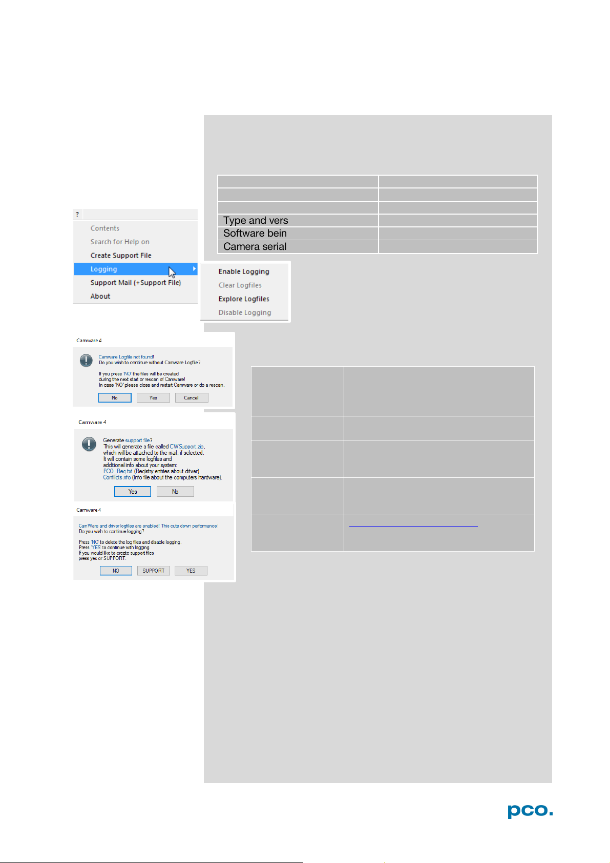
Enable log files:
? Help Menu → Logging → Enable
restart of Camware
Repeat
the workflow which produces the
faults
Open the Help
Click Support Mail (+ Support File) →
Save this file
(CWSupport.zip – don’t rename it)
Or visit our
http://www.pco.de/support/ and
A3.3 TROUBLE SHOOTING
If you have a question, which is not adequately addressed in this
manual, please contact PCO or your local dealer.
To speed your request, we need the following information:
How to create a logfile:
Logfile →Camware will ask you to
press NO to activate Logfiles after
Menu
website:
Camware will ask you: Generate
support file?
and send it to PCO Support
upload the support file with our
support form
49
Page 50

A3.4 RECYCLING
Repair
Before sending the camera for repair, first contact your local dealer
or PCO respectively.
When shipping the camera for repair, be certain to carefully pack the
camera with proper shipping materials. If possible use the original
packaging. Use the protection cap to protect the camera on the lens
thread.
Firmware, Software and Driver Update
You will find all necessary software and drivers on the accompanying
USB storage device.
For the latest versions please check our Website
.
To dispose your camera, please send it to PCO or take it to a local
recycling center.
The camera includes electronic devices, which can contain materials
harmful to the environment. These electronic devices must be
recycled.
50
Page 51

A4 INDEX
Keyword
Chapter
Page
Auto File Save
6.8.1
29
Averaging
6.5
23
Binning
6.3.2
17
Camware software
6
12
Codec Dialog
6.9.2
32
Connection options
A1.6
45
Contrast settings
6.3.6; 6.9.9
21; 38
Conversion Factor
6.3.3
18
Convert contro l
6.3.6
21
Cuda nvidia driver
4.1
8
Data sheet
A1.1
42
Demo mode (Camware)
6.9.1
31
Dimensions
A1.4
44
Direct record to file
6.9.2
32
Double image mode
6.3.3
18
Driver installation
4.1
8
File Formats
A2
46
First Image
5.3
11
Frame rate
6.3.1
16
IIR
6.5
23
Image Overlay
6.4
22
Input / Output possibilities
A1.6
45
Input window
A1.5
44
Installation 4 8
Live preview
5.3; 6.2
11; 13
Logfile
6.9.7
37
Maintenance
A3.2
48
Master Settings
6.2
13
Number of Images
6.2
13
Options
6.9.2
32
Pinout RJ11
A1.6
45
Play settings
6.4
23
Preview
6.2, 5.3
13, 11
Rear connections
A1.6
45
Recorder modes
6.3.4
20
Recorder memory settings
6.2
13
Recycling
A3.4
50
Rescan for cameras
6.9.4
34
Safety instructions
2
6
Save / Open / Print files
6.9.2
32
Sets (Camera Setting)
6.2
13
Settings Overview
6.8
28
Short Cut List
6.9.9
38
Support
A3
48
T
6.7
26
Time stamp
6.3.4, 6.4
20, 22
Timing
6.3.1
16
Trigger interface
A1.3
43
Trigger Mode
6.3.1
16
U
4.1
8
NOTE:
always the starting
A4 INDEX
The mentioned page is
page of a chapter!
Lowpass filter
humbnails
SB
51
Page 52

ABOUT PCO
pco.
ABOUT PCO
In 1987, PCO was founded with the objective to develop and to
produce specialized, fast and sensitive video camera systems, mainly
for scientific applications. Meanwhile the product range of PCO
cameras covers digital camera systems with high dynamic range,
high resolution, high speed and low noise, which are sold in the
scientific and industrial market all over the world.
Currently PCO is one of the leading manufacturers of scientific
cameras. Worldwide representatives, together with our own sales
department and technical support assure that we keep in touch with
our customers and their needs. The actual wide range of specialized
camera systems is the result of technical challenge and product
specific know-how. A design according to advanced techniques, a
high standard of production and strict quality controls guarantee a
reliable operation of the cameras. Our own developments in
conjunction with an excellent contact to leading manufacturers of
image sensors ensure our access to state-of-the-art CCD- and
CMOS-technology for our cameras.
Since 2001, PCO is located in its own facility building in Kelheim at
the shore of the beautiful and international river Danube. Here in the
county Bavaria, which is well known for its excellent support and
conditions for high technology companies, we share the benefits of
the simple access to high performance products and services in the
surrounding area.
Kelheim itself is a historical town, first documented in 866. The small
city is founded at the confluence of the Danube and the Altmühl,
which has been converted into the Rhine-Main-Danube bypass
channel for water transport. Located in Danube-valley, it is the heart
of a beautiful river and forest covered lime plateau landscape. It´s
landmark, the Hall of Liberation, was built by Ludwig I. in 1863 on the
Mount Michael and is visible from all over the city and valley. The
beautiful Danube-Gorge, which is protected as natural monument
since 1840, is located between Kelheim and the famous abbey
Weltenburg.
52
Page 53

pco.
 Loading...