

Page 1
pco.
dimax cs
pco.
user manual
Page 2
CO asks you to read this manual carefully before using the
P
pco.dimax cs camera system and follow the instructions.
Contact us for further questions or comments.
telephone +49 (0) 9441 2005 50
fax +49 (0) 9441 2005 20
email [email protected]
postal address PCO AG
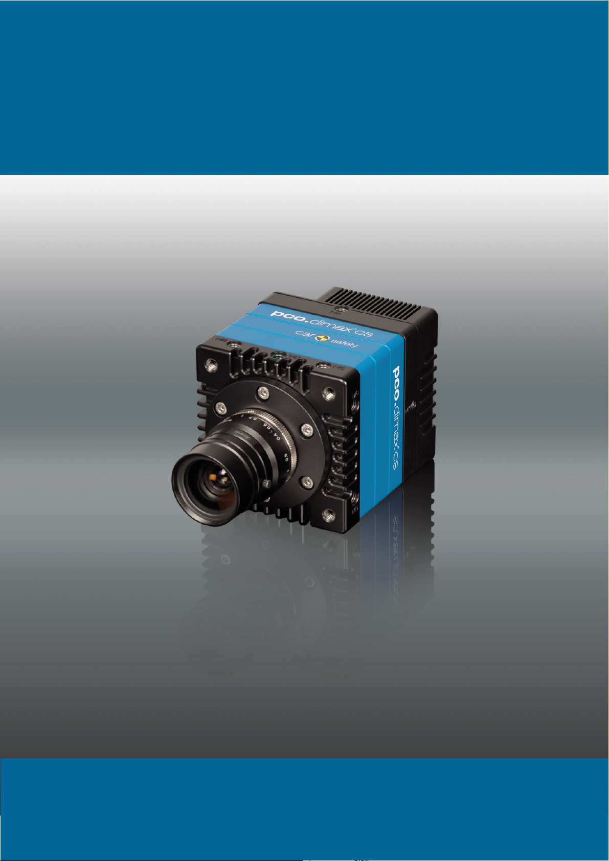
cover picture shows a typical PCO camera system.
The
Donaupark 11
93309 Kelheim, Germany
The lens is sold separately.
C
opyright © 2017 PCO AG (called PCO hereinafter), Kelheim, Germany. All
rights reserved. PCO assumes no responsibility for errors or omissions in
these materials. These materials are provided as is without warranty of any
kind, either expressed or implied, including but not limited to, the implied
warranties of merchantability, fitness for a particular purpose, or noninfringement. PCO further does not warrant the accuracy or completeness of
the information, text, graphics, links or other items contained within these
materials. PCO shall not be liable for any special, indirect, incidental, or
consequential damages, including without limitation, lost revenues or lost
profits, which may result from the use of these materials. The information is
subject to change without notice and does not represent a commitment on
the part of PCO in the future. PCO hereby authorizes you to copy documents
for non – commercial use within your organization only. In consideration of
this authorization, you agree that any copy of these documents, which you
make, shall retain all copyright and other proprietary notices contained
herein. Each individual document published by PCO may contain other
proprietary notices and copyright information relating to that individual
document. Nothing contained herein shall be construed as conferring by
implication or otherwise any license or right under any patent or trademark of
PCO or any third party. Except as expressly provided, above nothing
contained herein shall be construed as conferring any license or right under
any PCO copyright. Note that any product, process, or technology in this
document may be the subject of other intellectual property rights reserved by
PCO, and may not be licensed hereunder.
eleased September 2017 © PCO AG
R
pco.dimax cs user manual V1.04 © PCO AG, Germany
Page 3

TABLE OF CONTENTS
1. INTRODUCTION 5
1.1 INTENDED USE 6
1.2 REASONABLE FORESEEABLE MISUSE 6
2. SAFETY INSTRUCTIONS 7
3. SYSTEM COMPONENTS 8
4. INSTALLATION 9
4.1 NVIDIA CUDA DRIVER 9
4.2 GIGE DRIVER 10
4.3 CAMWARE 11
5. QUICK START 12
5.1 PREPARATION 12
5.2 START 12
5.3 FIRST IMAGE 13
6. CAMWARE 4 SOFTWARE 14
6.1 INTRODUCTION 14
6.2 CAMERA OVERVIEW / LIST 15
6.3 CAMERA PROPERTIES 17
6.3.1 TIMING 18
6.3.2 IMAGE SIZE 22
6.3.3 SENSOR CONTROL 23
6.3.4 MEMORY 24
6.3.5 RECORDING CONTROL 24
6.3.6 STATUS 27
6.3.7 HARDWARE I/O CONTROL 28
6.3.8 CONVERT CONTROL 30
6.4 IMAGE OVERLAY 32
6.5 RECORDER TOOLS 33
6.6 VIEW WINDOW 35
6.7 RECORDER (IMAGES) 36
6.8 SETTINGS OVERVIEW 38
6.8.1 AUTO SAVE 39
6.9 CAMWARE FEATURES 41
6.9.1 DEMO MODE 41
6.9.2 FILE MENU 42
6.9.3 CAMERA MENU 44
6.9.4 ACQUISITION MENU 45
6.9.5 VIEW MENU 45
6.9.6 WINDOW MENU 47
6.9.7 HELP MENU 47
6.9.8 VIEW WINDOW MENU 48
6.9.9 ADDITIONAL FEATURES 50
PPENDIX 51
A
A1 TECHNICAL DATA 52
DATA SHEET 52 A1.1
REAR PANEL 53
DIMENSIONS 54
INPUT WINDOW FILTER 56
M
OUNTING 56 A1.5
3
A1.2
A1.3
A1.4
Page 4

2 GIGABIT ETHERNET INTERFACE 57
A
QUICK INSTALLATION GUIDE 57 A2.1
NETWORK INTERFACE CARD 58
A2.2.1 IP ADDRESS CONFIGURATION 59
A2.2.2 JUMBO PACKETS / BUFFER SETTINGS 60
A2.2.3 RECOMMENDED HARDWARE 61
A2.2.4 NETWORK ENVIRONMENT/PATCH CABLE 61
A2.2.5 CABLE LENGTH 61
SINGLE/MULTIPLE CAMERA OPERATION 62 A2.3
A2.3.1 SINGLE CAMERA 62
A2.3.2 MULTIPLE CAMERAS 63
A2.3.2.1 SWITCH 63
A2.3.2.2 SEVERAL NICS 64
DRIVER INSTALLATION 65 A2.4
A2.4.1 UNINSTALL DRIVER 65
A2.4.2 DE/ACTIVATING FILTER DRIVER (WIN7/8) 65
CALIBRATION TOOL 66 A2.5
A2.5.1 FIRMWARE WARNING 67
A2.5.2 BLOCKED ACCESS 67
A2.5.3 NETWORK AND PACKET DELAY 68
A2.5.4 SET CAMERA IP ADDRESS & PACKET DELAY 69
A2.5.5 IMAGE DATA TRANSFER RATE 70
A2.5.6 CAMERA TEST 70
A2.5.7 RESET IP ADDRESS 71
A2.5.8 TOOL TIPS 72
HELP GUIDE 72 A2.6
PERFORMANCE 73
A3 ACCESSORIES 74
BREAKOUT CABLE 74 A3.1
EXTENSION BOX 74
LENS CAGE 76
A4 MOUNT ADAPTER 77
PCO F-MOUNT ADAPTER 77 A4.1
CHANGE F- TO C-MOUNT / FOCAL DISTANCE 78
A5 HD-SDI 79
A6 IMAGE FILE FORMATS 80
A7 CUSTOMER SERVICE 82
SERVICE 82 A7.1
MAINTENANCE 82
RECYCLING 82
LOGFILE / SUPPORT FILE 83
TROUBLE SHOOTING 84
A8 INDEX 85
ABOUT PCO 86
A2.2
A2.7
A3.2
A3.3
A4.2
A7.2
A7.3
A7.4
A7.5
4
Page 5
1 INTRODUCTION
pco.dimax cs1
pco.dimax cs3
pco.dimax cs4
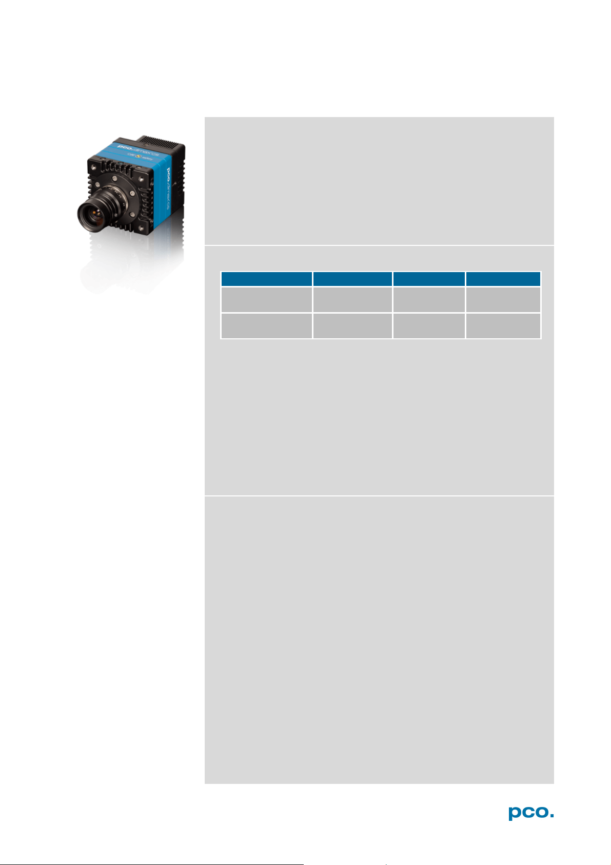
Maximum resolution
(pixel)
Maximum speed
@full resolution (fps)
• automotive crash tests
• hydrodynamics
1. INTRODUCTION
High-speed meets high resolution.
This high-speed 12 bit CMOS camera series incorporates advanced
CMOS and electronics technology. It is perfectly suited for highspeed camera applications such as material testing, offboard crash
and sled or impact tests or super slow motion movie clips. The
camera systems feature also a variety of trigger options to cover all
off-board and on-board applications required by the automotive
industry.
The camera’s main features are:
• 12 bit dynamic range
• Color or monochrome image sensor versions available
• Correlated Double Imaging for superior image quality
• Exposure time range 1.5 μs - 40 ms
• Integrated image memory (RAM 9 GB)
• Double shutter operation (optional)
• Gigabit Ethernet (GigE) data interface
• HD-SDI video output
• Multiple trigger interface
• IRIG-B (unmodulated) from B000 to B007 and B120 to B127
Example areas of application
1296 x1024 1920 x 1440 2016 x 2016
3086 1603 1102
• high-speed particle image
• short time physics
• spray analysis
• material testing
• tensile tests
• airbag inflation
• fast flow visualization
velocimetry (PIV)
5
• fuel injection
• combustion imaging
• semiconductor quality
control
• fast events in nature and
industry
• super slow motion movie
clips
• ballistics
Page 6

1.1 INTENDED USE
This camera system is designed for use by technicians, engineers
and scientists. It is a scientific measuring instrument, which provides
images. It is suited for applications with acceleration forces of up to
150G. The camera may only be used according to the instructions of
this manual. Provisions, limitations and operating conditions stated in
this manual must be respected. Unauthorized modifications or
alterations of the device are forbidden for safety reasons.
1.2 REASONABLE FORESEEABLE MISUSE
Overstress: It is not allowed to use the camera for applications with
acceleration forces higher than 150G.
Temperature: It is not allowed to use the camera beyond the
specified temperature range.
Use of lenses during onboard tests: only special C-mount lenses
(for high-G applications) are permitted. F-mount lenses must not be
used.
Accessories: It is not allowed to use the PCO Accessories for HighG
applications. The Extension box and the breakout cable must not
be used for high-G applications.
Open: opening the camera voids warranty.
6
Page 7
2 SAFETY INSTRUCTIONS
NOTICE
NOTICE
NOTICE
NOTICE
NOTICE
NOTICE
DANGER
WARNING
CAUTION
CAUTION
2. SAFETY INSTRUCTIONS
Read the safety instructions completely.
DAMAGED POWER CABLE OR POWER PLUG
Danger to life due to electrical shock!
Each time the camera is used, check the power cable for
damage.
ELECTRIC SHOCK WARNING DUE TO VOLTAGE PARTS INSIDE
Risk of injury due to electrical shock!
Never slide any items through slits or holes into the camera.
MOISTURE
Risk of injury due to electric shock if moisture enters the camera.
To avoid the risk of water condensation, protect the camera
against extreme changes of ambient temperature.
TRIPPING HAZARD
Risk of injury from tripping over loose cables.
Never position the cable in a way that it could become a
tripping hazard.
HUMIDITY, DUST OR RADIATION
Humidity, dust or x-rays could damage the camera.
Never operate the camera in humid or dusty environments
or in places with high level of x-ray radiation.
SHOCK & VIBRATION
To avoid damaging the camera it must be firmly mounted and
protected against strong shocks or vibrations.
Use the camera's mounting threads to secure it.
LENS MOUNTING
Do not force the lens onto the camera.
To protect the lens connector thread from damage, screw
in the lens gently to avoid thread damage.
LIQUIDS DAMAGE CAMERA
If liquids have penetrated the device.
Switch the camera off immediately, detach it from power and
contact PCO's customer support.
DAMAGED CAMERA HOUSING
If the camera has been dropped or the body is damaged.
Switch the camera off immediately, detach it from power and
contact PCO's customer support.
IF CAMERA IS NOT WORKING PROPERLY
In case all actions following this manual to get the camera working
properly were unsuccessful.
Switch the camera off immediately, detach it from power and
contact PCO's customer support.
7
Page 8
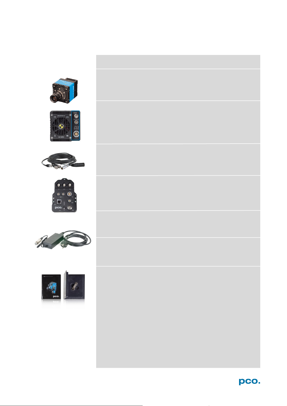
Rear Panel Connections (see A1.2)
Power Supply
Power Cord
3. SYSTEM COMPONENTS
The camera system includes the following parts.
Camera
F-mount + C-mount (exchangeable) optical connection
• Battery / Lens Controller
• LEDs indicate camera status
• Lemo Connector (Power - GigE - Trigger – Sync In/out – Stat out)
Breakout cable
RJ45 Cat6, BNC Sync In, BNC Trig In, XLR power
see chapter A3.1
Extension Box (optional)
see chapter A3.2
In: 100-240V AC 50-60Hz, 1.4A max. Out: 24V DC 2.71A
Standard IEC13 connector
Digital Camera Tools (USB flash drive content)
• Camware: software for camera control & image acquisition
• Manuals
• Driver & tools
• Software development kit (SDK) & demo programs in C and C++
8
Page 9
4 INSTALLATION
1
2
1
2
4. INSTALLATION
You will find all necessary files on the accompanying USB flash drive.
You may also download the latest versions of our software, camera
driver and third party software drivers from our website.
Minimum system requirements:
• Clock speed > 2.4 GHz (Intel Core i7)
• RAM 4 GB
• Windows 7 or higher (no server version)
• Full-HD display
• Gigabit Ethernet GigE (1000 Mbps network interface card)
4.1 NVIDIA CUDA DRIVER
Update your NVIDIA driver for Camware 4. In case of an old driver
version GPU Processing will not work and therefore slow image
processing.
If GPU Processing is disabled and shown grayed, update your
NVIDIA driver or check the website of the computer manufacturer for
graphic card driver updates. Your NVIDIA driver version must be at
least 333.11 or higher.
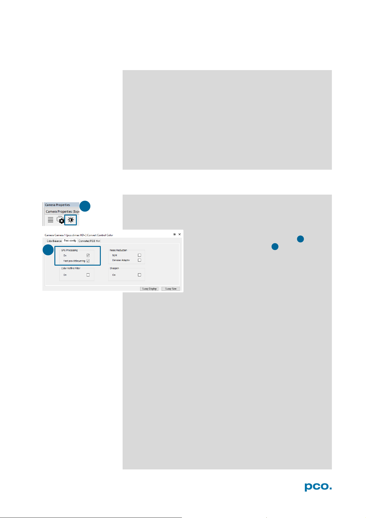
Check if GPU Processing is activated by having
a look into the Proc config settings in the
Convert Control window (see Convert
Control chapter 6.3.8).
9
Page 10

1
4 2 3
1 2 3
4
NOTE
installs both
allowing former GigE cameras to run
If installer fails, use
5
5
4.2 GIGE DRIVER
NOTE
uninstaller, remove all
old files and then try
again.
First install the PCO GigE driver to your computer, from the attached
usb flash drive or from the PCO website www.pco.de
Before installing, you have to remove previously installed GigE
driver. The installer will do this for you. Or open control panel →
programs and functions → and uninstall PCO GigE driver.
• Start the GigE driver setup and follow the instructions.
• Choose installation directory.
• GigE driver installation is completed.
• Reboot your computer to complete the installation.
• Start Calib Tool see A2
This installation process
drivers: Gen2 and the former Gen1 V3.1
properly.
.
10
Page 11
4 INSTALLATION
1
2
3
4
1
1
2
3
4
4.3 CAMWARE
The Camware Windows application software enables to control every
camera parameter or setting. Images can be displayed on a monitor
and may be downloaded and stored. The enclosed USB flash drive
contains installation files for the software for latest Windows
operating systems in 32 / 64 bit.
After a successful installation, you will find the program file Digital
Camera Toolbox in your program directory and a Camware 32 / 64
button on your desktop. Other helpful tools are also installed in the
same directory.
To uninstall the Camware program, use the Software feature under
Windows’ System Control.
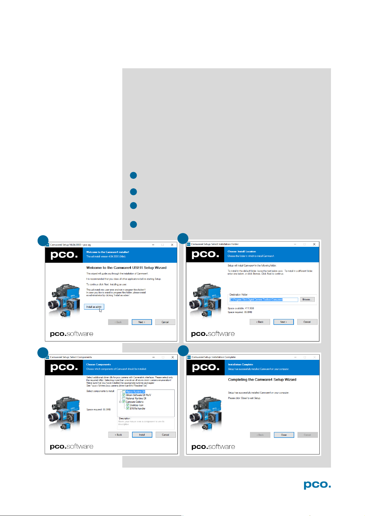
Follow the installation wizard
• Install Camware as Admin to install to program folder, instead it
will be installed only to user folder
• Choose install directory
Choose components: Select additional drivers for Camera Link
•
interface (not recommended for pco.dimax cs)
• After the next two screens installation is complete
11
Page 12
NOTE
5. QUICK START
5.1 PREPARATION
In order to get familiar with your new camera and software it might be
helpful, first to aim the camera at an object easy to focus and visible
at normal light conditions.
• Computer is turned on
• Installation is finished (see chapter 4)
• An appropriate lens is attached (remove cap) or the camera is
attached properly to the microscope, spectrograph or other
scientific device
• Camera is connected to the power supply
• Camera is connected to the computer and switched on
• Camera is booted and ready after 5 to 20 s when a beep sounds
5.2 START
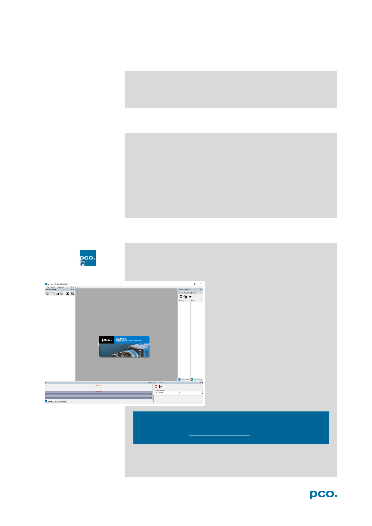
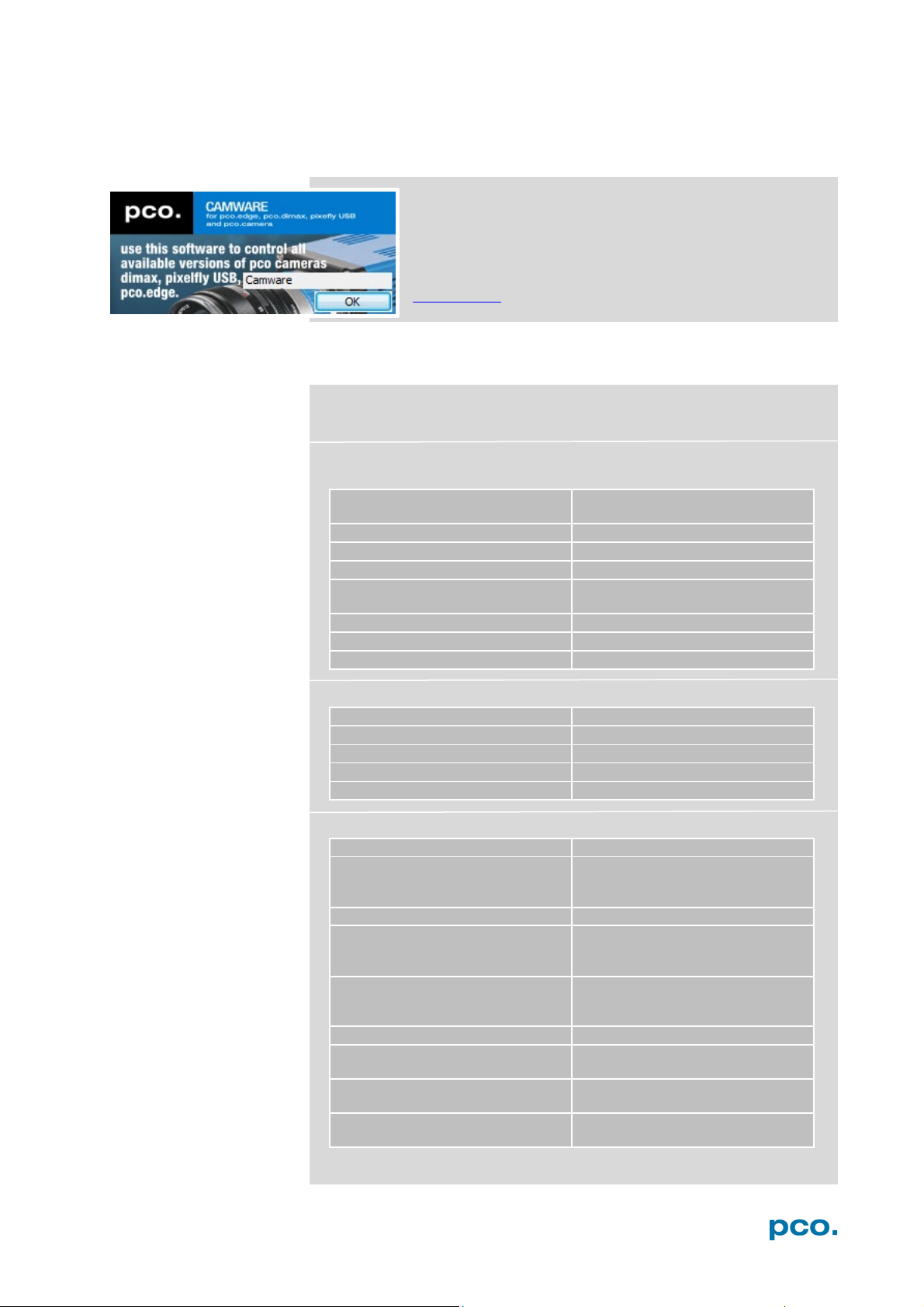
Start Camware and the graphical user interface will start up:
Always install latest Camware version to get the full functionality of
your pco camera (www.pco.de/support)
.
12
Page 13
5 QUICK START
NOTE
2
3 4 5
6
2 3 6 4 5
1
1
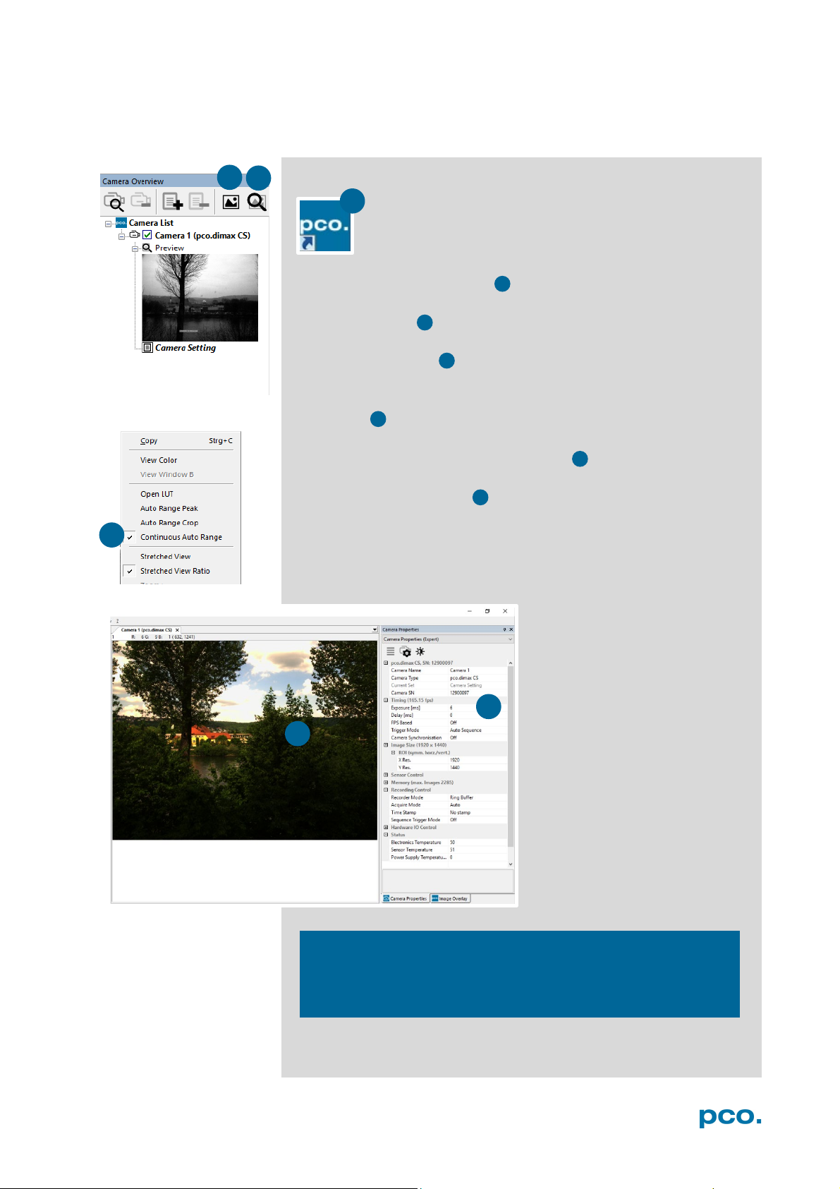
5.3 FIRST IMAGE
Follow the instructions:
• Camware must be started
• A view window is shown automatically, if not open a new one
• Start live preview
• Right-click into the view window and apply Continuous Auto
Range
• You may have to adjust exposure time , aperture and focus
• Now you should clearly see the object in the window
If you need to change exposure
time (e.g. the image is still either
too dark or too bright), go to
chapter 6.3.2.
For recording and saving
images, see chapter 6.3.8 and
chapter 6.6 for detailed
information.
Live preview: Useful for fast and easy camera adjustment and
focusing. Does not record and store images.
13
Page 14
6.3.1 TIMING
Timing /Trigger modes/
6.3.2 IMAGE SIZE
ROI / Sensor format / Binning
6.3 .3 SENSOR CONTROL
CDI / Double shutter / Temperature
6.3.4 MEMORY
Camera Internal memory (RAM)
6.3.5 RECORDING CONTROL
Recorder Acquire Mode /
Timestamp / Sequence trigger
6.3.6 STATUS
Temperature
6.3.7 HARDWARE I/O CONTROL
Input and Output Options
6.3.8 CONVERT CONTROL
Contrast, Saturation, Gamma…
6.4 IMAGE OVERL AY
Overlay for recorded images
6.5 RECORDER TOOLS
Record / Play and Settings
6.6 VIEW WINDOW
View window functions
6.7 RECORDER (I MAGES)
Preview of recorded images
6.8 SETTINGS OVERVIEW
Overview of all parameter settings
6.9.1 DEMO MODE
If no camera is connected
6.9.2 FILE ME NU
Open / Save / Print files / Direct
Dialog / Lookup table
6.9.3 CAMERA MENU
Camera control / Close / Rescan
6.9.4 ACQUISITION MENU
Live preview / Acquire sequence /
switching
6.9.5 VI EW MENU
B/W or Color window / Convert
6.9.6 WINDOW MENU
New / Close / Split window
6.9.8 HELP MENU
Create Support file/ Logging /
6.9.8 VIEW WINDOW MENU
Right-click menu: Zoom; Flip;
6.9.9 ADDITIONAL FEATURES
White Balance, Contrast, ROI by
6. CAMWARE 4 SOFTWARE
PCO’s Camware is an outperforming software for camera
control, image acquisition and archiving of images in
various file formats. This chapter provides a detailed
description of all Camware functions.
Camware works with any kind of PCO camera. Visit
www.pco.de
6.1 INTRODUCTION
Chapter 6.2 Camera Overview / List: shows all connected cameras
and all set recording profiles
Chapter 6.3 describes the Camera Properties window. This is the
main interface for all camera settings.
the latest version of this software.
synchronization
Chapter 6.5 / 6.6 / 6.7 / 6.8 describe the recording functions
Chapter 6.9 introduces to further Camware features
record to file / Options / AVI Codec
Auto camera RAM segment
Control / Toolbars / Application
Look / Reset layout to default
Support mail / About Camware
Mirror; Rotate…
Mouse, Short-cut list
14
Page 15
6 CAMWARE 4 SOFTWARE
1
1 2 3
4
2 3 4
5
6
5 6 5
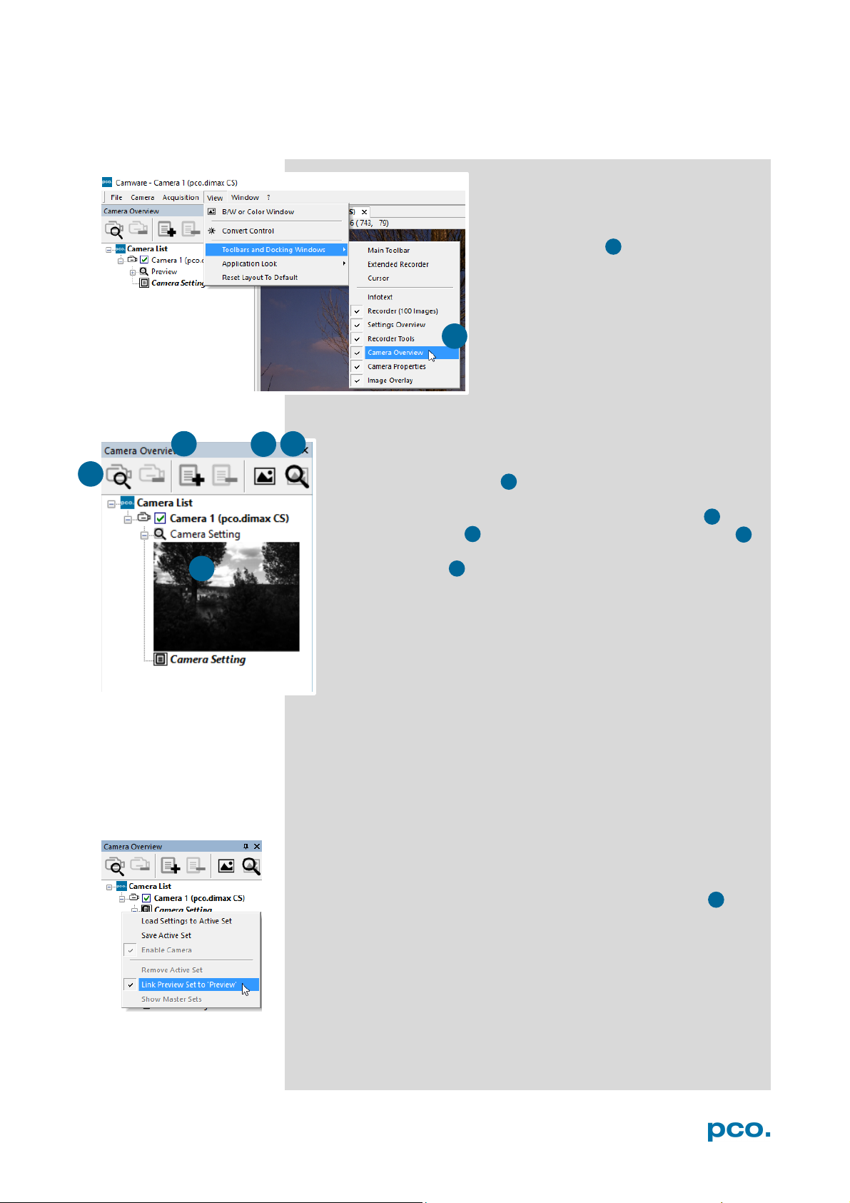
6.2 CAMERA OVERVIEW / LIST
The Camera Overview window supports management of more
than one PCO cameras and displays a list of the connected ones.
Camware is able to scan 2 for connected cameras or close a
connected camera. It allows to define several different Settings
for each camera (max. 30 sets per camera → add new set 3 ).
New view windows 4 can be opened and the Live Preview 5
function started. When opened up, the Preview shows a small
preview window 6 (always monochrome) integrated in the
camera list.
Live preview facilitates the aperture and focus adjustment,
allowing a first look at your object.
If closed, open the Camera Overview
window by selecting the View tab and
Toolbars and Docking Windows →
Camera Overview.
During Live preview Trigger and Acquire mode are set to Auto.
Camera Setting: all presettings, such as resolution and frame rate in
the Camera Properties (see 6.3) are saved to Camera Settings.
Define different Settings with different Preferences in Camera
Properties for each of your experiments. Settings can be switched
easily at any time (not during record) and copied to other cameras.
Link Preview Set to ‘Preview’
When Link Preview Set to Preview is ticked the Preview will always
be active with the set parameters when starting a Live Preview 5 .
In case this function is deactivated, the Live Preview will always
show live images with the parameters of your active setting.
Setting a higher exposure time for Preview set and linking it to the
preview function is beneficial if preview light conditions are different
from those in recording situations.
15
Page 16
1
2
3
1 2 3
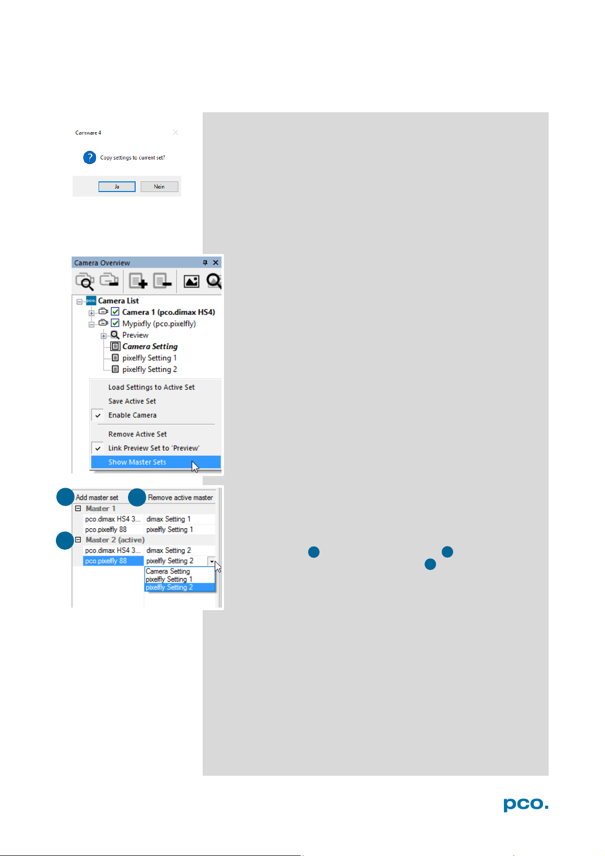
Click and drag camera setting: to copy e.g. Camera Setting 1 to
Camera Setting 4, just drag & drop Setting 1 to Setting 4 and
Camware will ask to confirm it. It is possible to copy each setting to
every camera.
Master Sets
This function facilitates image acqusition with multiple cameras.
Defining two or more Master Sets allows easy switching between
different predefined settings for each camera during an
experiment. Each image acquisition or experiment can be
recorded with its own Master Set.
To display Master Sets, right-click in the Camera Overview
window and click Show Master Sets.
Master Set window
Define different Master Sets. Select individual Camera Settings
within each Master Set.
Functions:
Add Master Set or Remove active master .
Activate it by clicking on one of your sets .
16
Page 17
6 CAMWARE 4 SOFTWARE
1
2
3
1
2
3
4
4
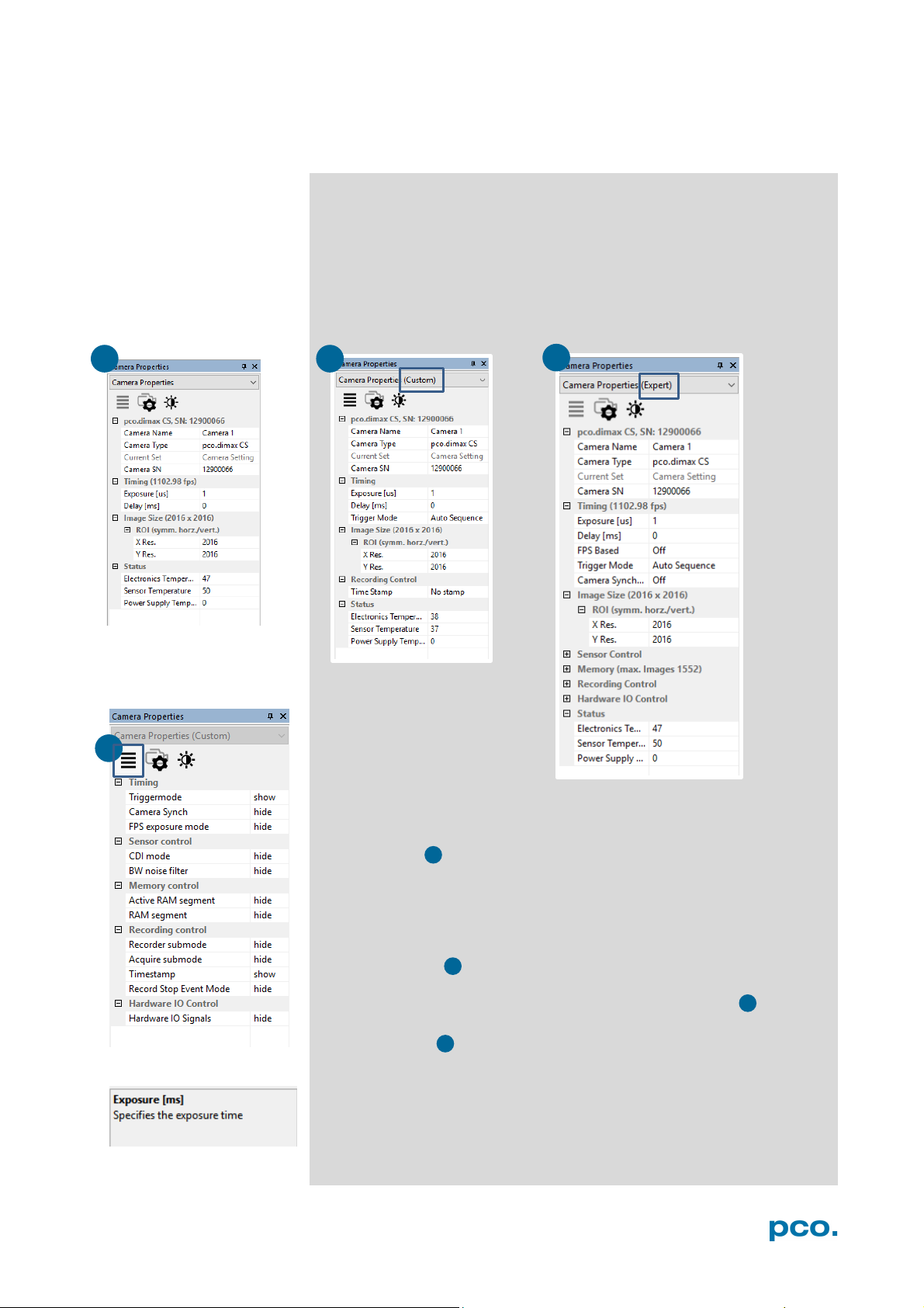
6.3 CAMERA PROPERTIES
The Camera Properties window in Camware is the main interface for
all camera settings. The active set in Camera list is adjusted here.
The former topic Camera Control (known from Camware 3.x) and
the Convert Control (see 6.3.8) can be opened additionally.
Three view options with various functions can be selected: Basic,
Custom and Expert.
Basic mode 1 only shows camera name, timing, image size and
status. In Basic Mode the frame rate is always calculated
automatically based on the selected exposure time, i.e. while
exposure time is increased, frame rate decreases. It is recommended
for Camware beginners.
Custom mode shows several more setting possibilities and
functions are hidden or shown by the Custom Properties Button.
Beside the Basic mode many more options are selectable.
Expert mode (for advanced users) shows all possible camera
feature settings.
An explanation for every feature is displayed below the properties
dialog.
17
Page 18
Rxposure
n
Readout
n + 1
n + 2
n
n + 1
n + 2
t
t
NOTE
Exposure
n
n + 1
n
n + 1
n - 1
t
t
1
6.3.1 TIMING
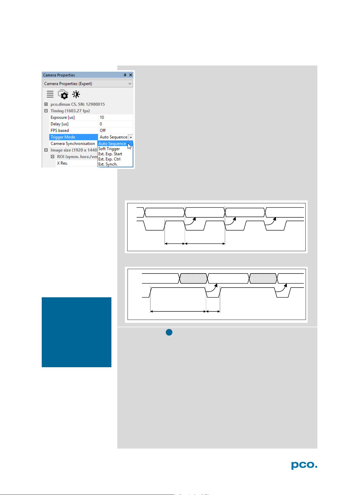
General Information
The most important parameter for a high-speed camera is the
frame rate. The upper limit of the frame rate is defined by the
exposure time and the readout time.
In this context trigger means exposure trigger, i.e. the trigger
signal controls the exposure of a single image.
Exposure and readout of one image are done simultaneously,
i.e. while image n is being read out from the sensor, image n+1
is already integrated within the sensor’s pixel.
Readout time correlates with the resolution: if you select a
smaller resolution (fewer rows and columns) the readout time is
also reduced.
In case of short exposure times, the readout time is the limiting
factor, i.e. a new image can only be recorded, if the previous image
has been read out.
For long exposure times, the exposure time is the limiting factor:
Readout
exp
readout
As the pco.dimax cs is
a high-speed camera,
triggering single images using the Soft
Trigger button will
result in a significantly
degraded image quality (noisy images).
exp
sys
Trigger Modes
Auto Sequence: the camera optimizes the image recording to
achieve the best possible frame rate. In the Auto Sequence
Exposure Control mode, the camera he highest possible frame rate
against the set exposure time and the time required for a frame
readout. Upon a start command the sequential recording starts and
lasts until a stop command..
Software Trigger: single images are recorded by this Camware
command. A single image is acquired by pressing the Single Trigger
button. This button appears after pressing the Start Record button.
Other signals have no influence on this operating mode.
External Synchronization (BNC Sync In): the pco.dimax also uses
an external synchronization signal feeding a phase-locked loop (PLL)
in the camera.
18
Page 19
6 CAMWARE 4 SOFTWARE
(difference <
random, whether or
BNC Sync In
Exp Trig Signal
BNC I/O
BNC I/O
accepted
accepted
acc.
not acc.
BNC I/O
acc.
not acc.
BNC Sync in
BNC I/O
acc.
not acc.
acc.
not acc.
acc.
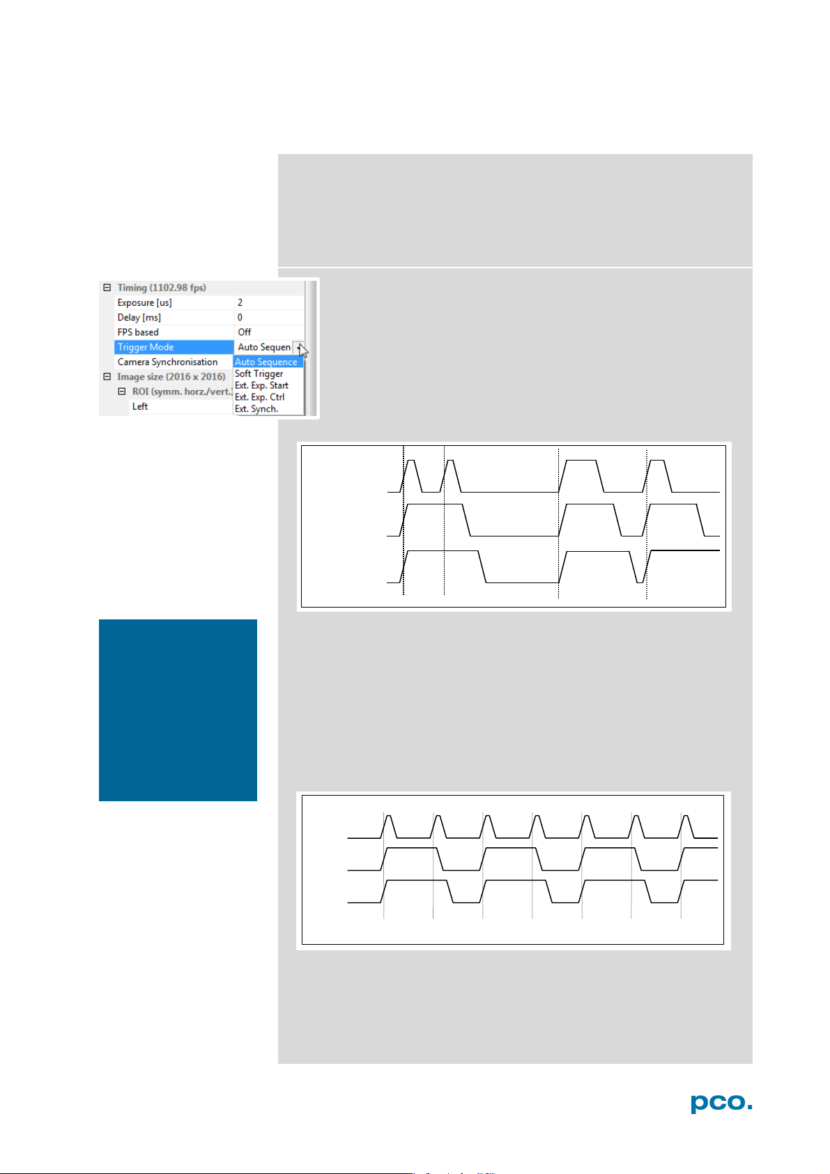
Advantages of the PLL (Ext synch) solution:
• Availability: only for frequenc ies of 1, 10, 100 or 1000 Hz
• Reliability: in case of dropouts of the external synchronization signal, the
synchronization is kept internally by the PLL signal with only small d eviation.
• Noise immunity: interference on the signal is automatically detected and discarded.
• Flexibility: the cameras can even be set to different frame rates, as long as all
frame rates are an integer multiple of the synchronization frequency.
External Exposure Start (Ext. Exp. Start):
The image acquisition is triggered by an external signal. The
single trigger button acquires a single image for a test.
In Ext. Exp. Start exposure control mode, image acquisition
starts by the falling or rising edge of the signal at the BNC Sync
In input (see Appendix A1.2). The frame rate cannot be set, as
the frame rate is defined by the frequency of the external signal.
However the exposure time and ROI (Region of Interest)
settings affect the maximum possible frame rate.
NOTE
If the trigger rate of
the external signal is
very near the maximum possible frame
rate
1/1000), then it will be
not a trigger is accepted!
Exp Stat (out)
Busy Stat (out)
A new trigger is possible after t
readout
or (t
exp
+ t
) (whichever is longer)
sys
after the preceeding trigger. The Busy Status (BNC I/O) signal (see
chapter 6.3.6) indicates whether a new trigger is accepted. The
maximum achievable frame rate in External Trigger mode is
negligibly less (about 0.1%) than in Auto Sequence mode. If the
trigger rate of the external signal is higher than the maximum possible
frame rate, every second trigger pulse is ignored. Therefore the actual
frame rate drops to half of the external trigger rate. If the trigger rate
is increased further, then only every 3
rd
, every 4th etc. trigger edge will
be accepted.
Exp Trig Sig
Exp Stat (out)
Busy Stat (out)
In order to avoid trade-offs at maximum frame rate use either the
Busy Status signal BNC I/O (see chapter 6.3.7) or make sure the
external trigger rate follows this condition:
Ext. Trigger Rate ≤ f
/ 1.001.
max
19
Page 20
NOTE
ware trigger. The
recommended for
quired!
t
-0 /+25ns t
configurable 0…1ms
rsys
fsys
t
Exposure
BNC Sync In
t
t
t
t
t
BNC Sync In
BNC I/O
BNC I/O
Busy Stat. (out)
t
accepted
accepted
acc.
not acc.
NOTE
from T0 Trigger and
should not be mixed
frames based on a
terminates the active
Sequence Trigger
Exposure trigger differs
up.
Exp. Trig. (BNC Sync
In) triggers single
falling / rising edge.
T0 Trigger (BNC Trig In)
recording with a single
signal edge and allows
to record a predefined
number of images after
T0 (see chapter
6.3.5
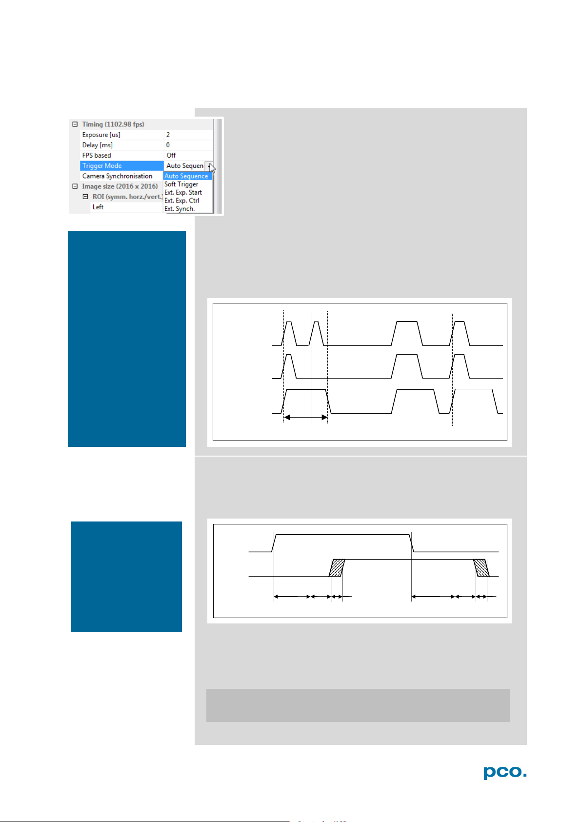
External Exposure Control (Ext. Exp. Ctrl):
An external signal applied to the exposure trigger input (BNC
Sync In see chapter 6.3.7), controls start and duration of the
exposure.
In trigger mode Ext. Exp. Ctrl a new exposure starts by the
falling or rising edge of the signal at the BNC Sync In input. The
exposure is finished when the opposite edge is detected. Thus
in this mode, the start as well as the length of the exposure time
can be externally controlled. No further settings can be made,
as the image timing is completely controlled by the exposure trigger
signal yet. There is a maximum exposure time. If the trigger pulse is
longer than 20ms, the integration will be stopped at 20ms.
A new trigger is possible after t
readout
or (t
exp
+ t
) (whichever is longer)
sys
following the preceding trigger. The Busy Status (BNC I/O) signal
(see chapter 6.3.7) indicates whether a new trigger is accepted.
Exp. Trig. Signal
Exp. Stat. (out)
readout
Mode).
There is no specified
timing for the soft-
software trigger is not
applications where an
exact timing is re-
Detailed Timing for External Exposure Start /Control
The detailed timing for external trigger includes system delay times,
an adjustable additional delay time and the jitter.
Exp. Trig. Signal
rsys
delay
jit
Parameters for the following tables:
• Width of the selected ROI must be a multiple of 24
• Data is not applicable in trigger mode External Exposure Start.
• Trigger edges occurring within t
+ 200ns after a previous
delay
trigger are ignored.
jit:
t
+ t
system delay times depending on ROI (see next page)
delay
fsys
delay
jit
20
Page 21
6 CAMWARE 4 SOFTWARE
camera type
exposure time
delay time
pco.dimax cs
1.5 μs … 40 ms
2 μs … 40 ms
2
Timing
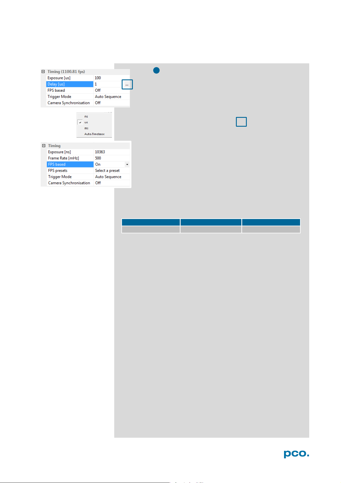
The exposure and delay time can be precisley set in steps of 1
μs. The effective stepsize depends on the operation mode.
The slider and the up/down control refer to the blue highlighted
unit. The resulting frame rate is derived from this setting. Delay
time setting is not recommended for high-speed applications.
Easily change time base by clicking on … and the respective
window opens.
FPS based: The camera optimizes the image recording to
achieve the selected frame rate. The exposure time is limited to
1/fps, lower values can be selected. (Selectable for Auto
Sequence trigger mode and preset for External synchronization
mode.)
First the frame rate is set. If the time required for readout of the image
is longer than 1 / frame rate, then the frame rate will be reduced to 1 /
readout.
t
If FPS based is selected and the selected exposure time requires a
lower frame rate, the exposure time will be cut to the maximum
possible time at that frame rate.
The minimum selectable frame rate is 0.465 Hz, but it only makes
sense to use: ≥ 20Hz.
21
Page 22
increments horizontal:
24 pixel steps
increments vertical:
4 pixel steps
minimum ROI:
24 x 8 pixels
1
1 2 3
3
2
6.3.2 IMAGE SIZE
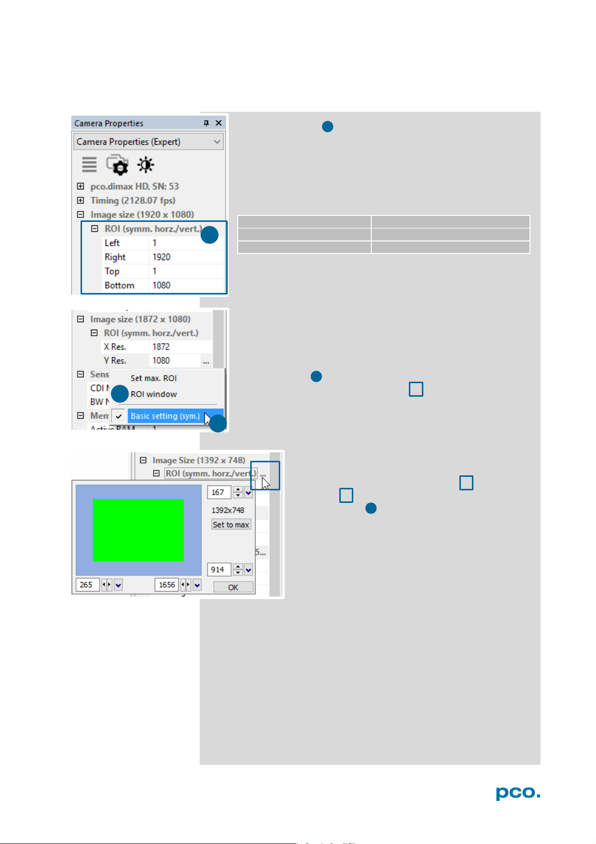
Region of Interest
To speed up frame rate and to save storage space, the ROI
(region of interest) selects only a part of the sensor to be read
out. Due to the sensor structure and readout electronics the
selectable region is always symmetric to the center.
pco.dimax cs
Basic Setting:
Activate Basic Setting by clicking on … to easily set a ROI by
just typing in the horizontal and vertical resolution in pixels.
ROI window
Select the ROI (symm. horz./vert.) menu and
activate ROI Window by clicking on ... or use the,
or use the … right to the X Res / Y Res and click
on ROI window.
The ROI window will open and it is possible to set a
new Region of Interest by dragging a window with
the mouse or by keying in the values.
22
Page 23
6 CAMWARE 4 SOFTWARE
status expos
General timing for the double image mode
readout
image n, 1st exp.
wait
ttd
te1
te2
image n, 2nd exp.
tif
exp trig
image n+1,
1st exp.
t
te1: exposure 1 te2: exposure 2
readout
1 23
1
2
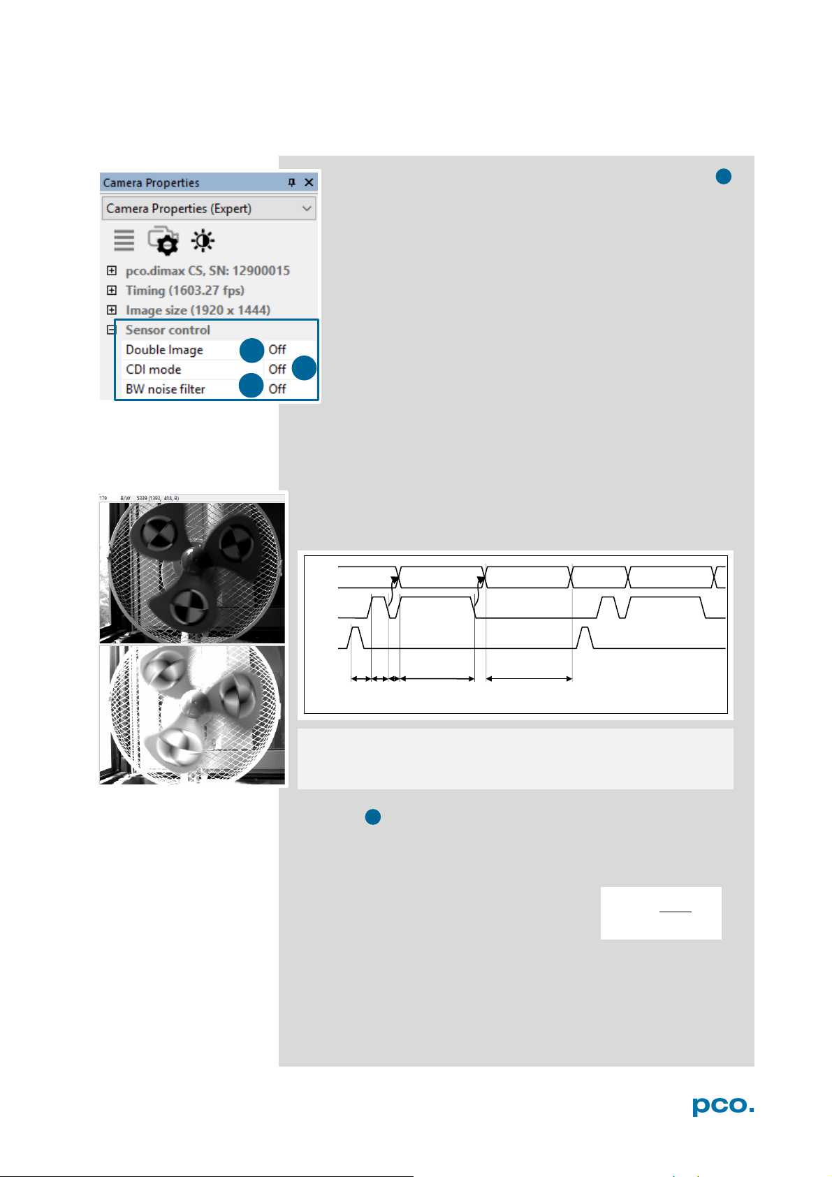
6.3.3 SENSOR CONTROL
Double Image / Double Shutter (only for monochrome sensors)
This feature is widely used for particle image velocimetry (PIV)
measurements and is an optional feature of the pco.dimax cs
series. The first exposure time t
the available range of the pco.dimax camera. The second
exposure time t
second exposure is the readout time of the first image. The
interframing time t
exposure #1 and start of exposure #2.
As can be seen the maximum frame rate of the double image
mode (where frame rate is defined as the frequency of the
double images) will drop to just half the value compared to the
standard mode.
The double image mode will work only in the trigger modes Auto
Sequence and External Exposure Start. See 6.3.1.
Note: to achieve a blur free second image the environment should be
kept dark and the exposure duration of the second image determined
by a flash light.
Timing Diagram for Auto Sequence
may be any exposure time of
e1
cannot be directly adjusted. The length of the
e2
denotes the transition time between end of
itf
readout
ttd: trigger delay time tid: intrinsic delay
tif: interframing time t
: readout time
CDI mode
The correlated double image (CDI) mode records images with
increased dynamic range and a 30% better performance on the weak
signal side of the images (at the expense of half of the usual frame
rate, because double images are acquired).
The min. exposure time is calculated as follows:
t
= min. exposure time
exp
= max. frame rate
f
CDI
Example:
resolution = 1920 x 1080 pixel; f
In this case t
To increase t
is both minimum and maximum exposure time.
exp
decrease frame rate or resolution.
exp
= 1067 fps → t
CDI
exp
= 467 μs
1
=
2∗
23
Page 24
NOTE
l camera
recording activation
by software (press
4
3
1 2 3
1
2
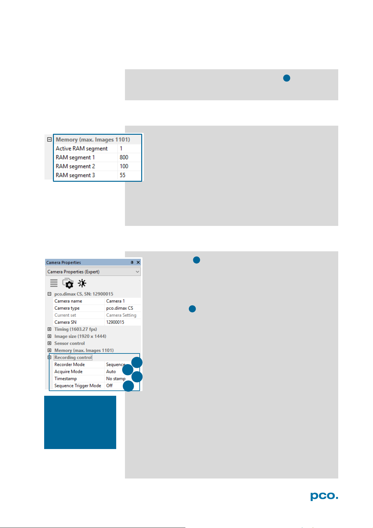
6.3.4 MEMORY
B/W Noise Filter (only available for pco.dimax cs b/w)
Intelligent spatial noise filter.
The Memory area controls the pco.dimax built-in memory.
The RAM has four segments. In Camware only three are usable
to save images. The fourth is used by Camware itself for internal
processes.
You may record into three different segments and to set the
exact number of images in each segment. Camware always shows
the maximum number of images (depending on RAM size and chosen
ROI).
Active RAM Segment: choose the active segment: 1, 2 or 3.
6.3.5 RECORDING CONTROL
Recorder Mode
In Sequence mode the camera stops after the memory (i.e. the
active RAM segment) is completely filled. In Ring Buffer mode
the camera records until it is stopped – overwriting the previous
images continuously.
Acquire Mode
The Acquire Mode enables or disables the recording by an
external signal.
If set to Auto all images are accepted and all images taken are
saved. A signal at the BNC Trig In input (see 6.3.6) is ignored
when set to Auto.
If set to External, the camera only records images, when the
external signal applies.
Acquire mode still requires initia
record button)!
The signal at the BNC Trig In input does not affect the sensor's timing
scheme.
The BNC Trig In is sampled at the beginning of the exposure, shown
by the rising edge of the exposure status (BNC I/O) output.
BNC Trig In input high: (low, when inverted): image saved to
memory
BNC Trig In input low (high, when inverted): image lost (not saved
to memory)
24
Page 25
6 CAMWARE 4 SOFTWARE
pco.dimax model cs
tsu
60 ns
BNC Trig In
BNC Sync In
tsu
th
BNC Trig In
BNC I/O
accepted
not acc.
not acc.
accepted
BNC Sync In
BNC Trig In
BNC I/O
saved
not saved
not saved
saved
Exp Stat (out)
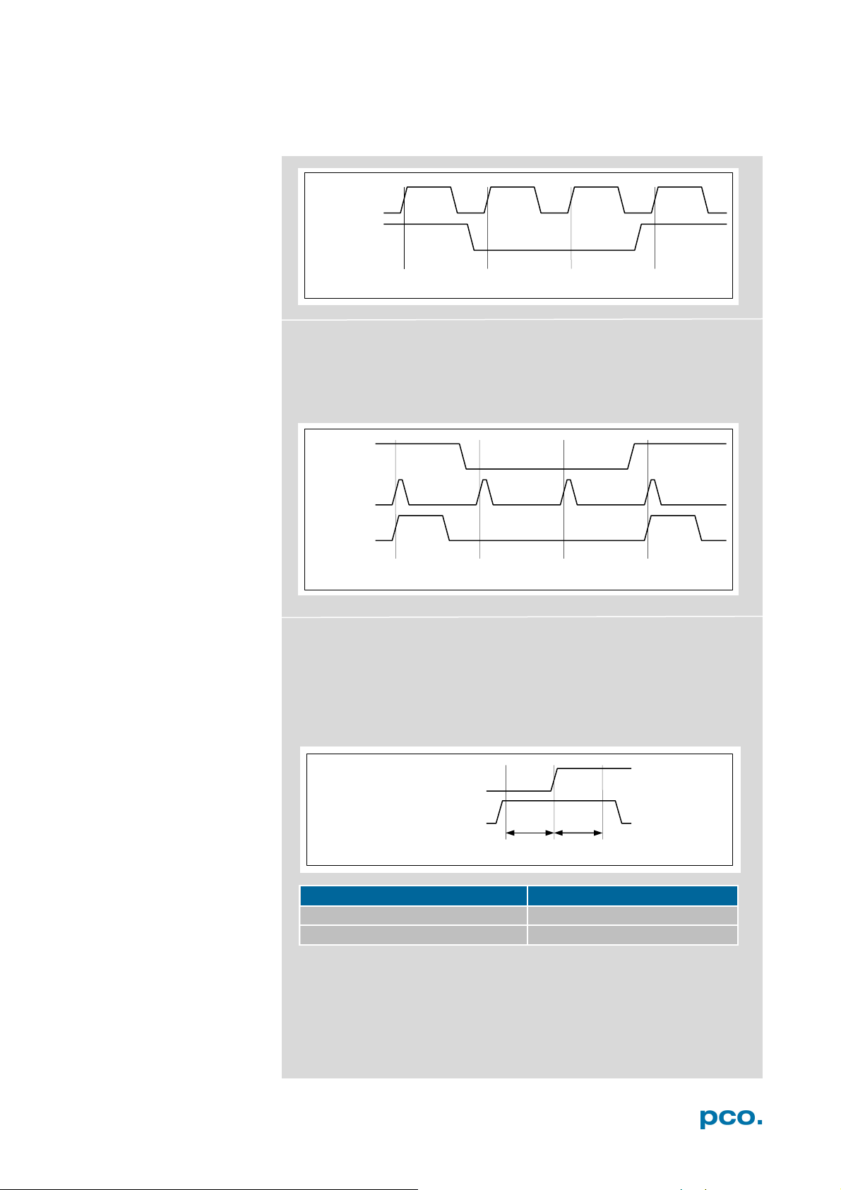
In trigger mode External Exp. Start, the BNC Trig In input acts as a
gate for the trigger signal. A rising trigger edge (rising, falling when
BNC Sync In is inverted) is accepted only when the BNC Trig In
signal is high (low, when inverted).
Exp Trig (in)
Exp Stat (out)
In trigger mode External Exp. Ctrl, the BNC Trig In input works very
similar to the mode External Exp. Start. However, the BNC Trig In
input is ignored for the edge which is closing the exposure time (an
already started exposure will be finished).
When using BNC Trig In in external trigger modes, the following
timing specification should be met:
Exp Trig (in)
Acq Enbl (in)
th 60 ns
If the BNC Trig In signal changes within the window of tsu (set up) to
t
h
ignored.
(hold), the behavior is random. The trigger may be accepted or
25
Page 26
3
BNC Trig In
Record State
1
Exposure
2 4 3 5 6 7 8 9 10
Stop Event / T0 Trigger
4
Delay Images = 10
4
1 2 3
1
2
3
3
NOTE
sure signal polarity is
type at the acquire
enable (BNC Trig In)
input) for TTL signal
Timestamp
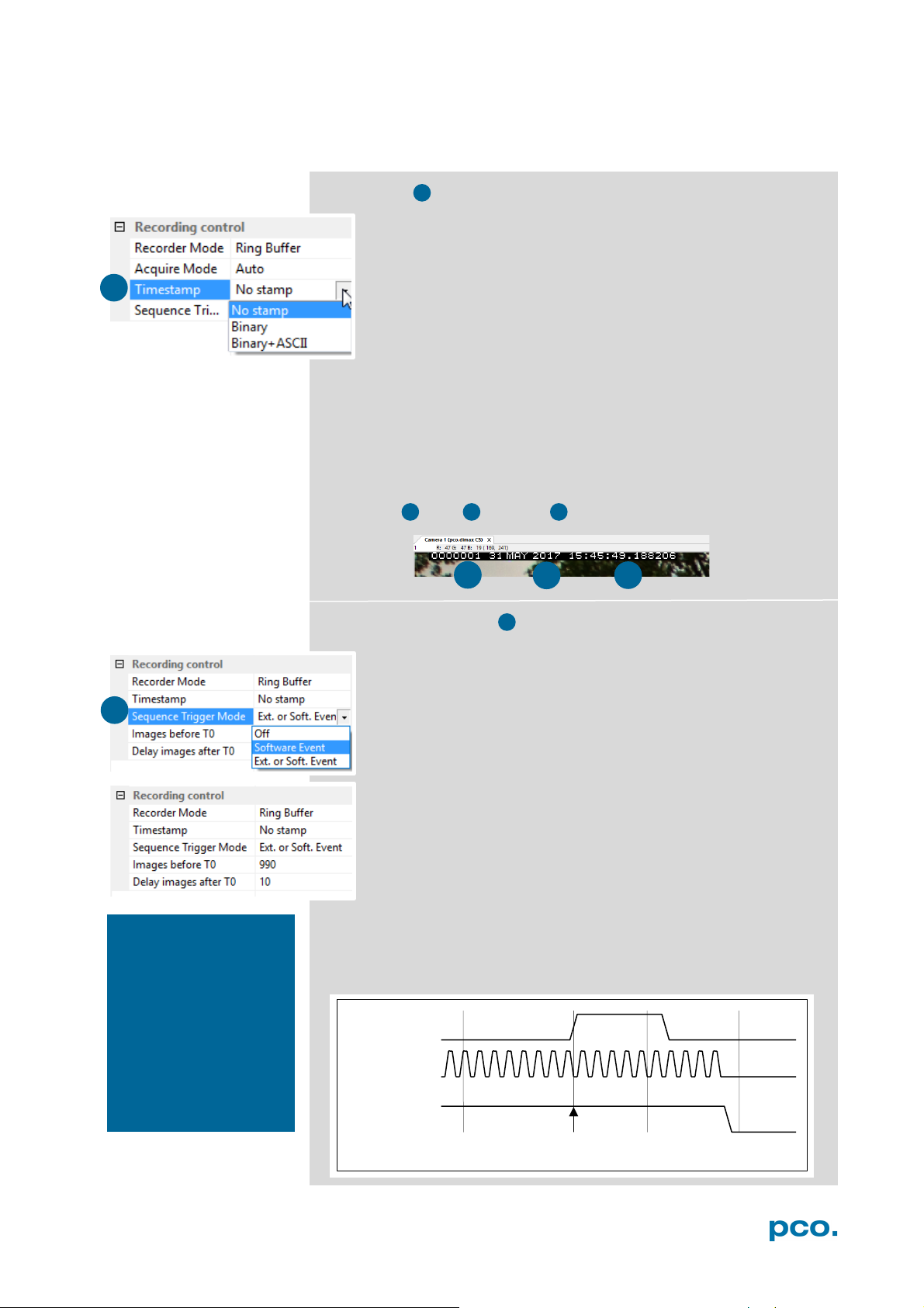
A time stamp can be placed into the upper left corner of the
image. It can be either set to no stamp, binary or binary with
text. The time resolution is 1 μs.
In binary mode the first 16 pixels will be filled with the time
stamp information (binary code). The numbers are coded in
binary coded decimal (BCD) with one byte per pixel. Every pixel
contains two digits. If the pixels have higher resolution than 8
bits, then the BCD digits are right bound adjusted and the upper bits
are zero. For further information refer to the SDK manual.
In binary and ASCII mode text will be placed into the image its
content (271x 8 pixels).
The timestamp shows the end of the exposure time.
Three different information is stamped onto the image: number of
the image , date and time .
When using the
Extension box make
inverted to a TTL signal
Sequence Trigger Mode
The Sequence Trigger Mode enables the user to stop
capturing a sequence of images via an external signal, so called
T0 trigger. The user can set the number of images before and
after the trigger event.
Since the Sequence Trigger Mode uses the BNC Trig In input
(see chapter 6.3.6), the acquire function cannot be used. The
acquire mode thus has to be set to Auto.
The camera already records images into the selected RAM and
may have filled it completely before the Sequence Trigger
Mode starts. Therefore the recorder mode should be set to
Ring Buffer.
Off: function is not active; signal at BNC Trig In does not stop
the record.
Software Event: only a software command can stop the sequence.
Ext. or Soft. Event: both, a signal edge at BNC Trig In or a software
command can stop the sequence.
input. (Trig In BNC
type.
26
Page 27
6 CAMWARE 4 SOFTWARE
800 images
RAM 1000 images
stop event /T0 Trigger
#1000
Delay Images = 800 (80%)
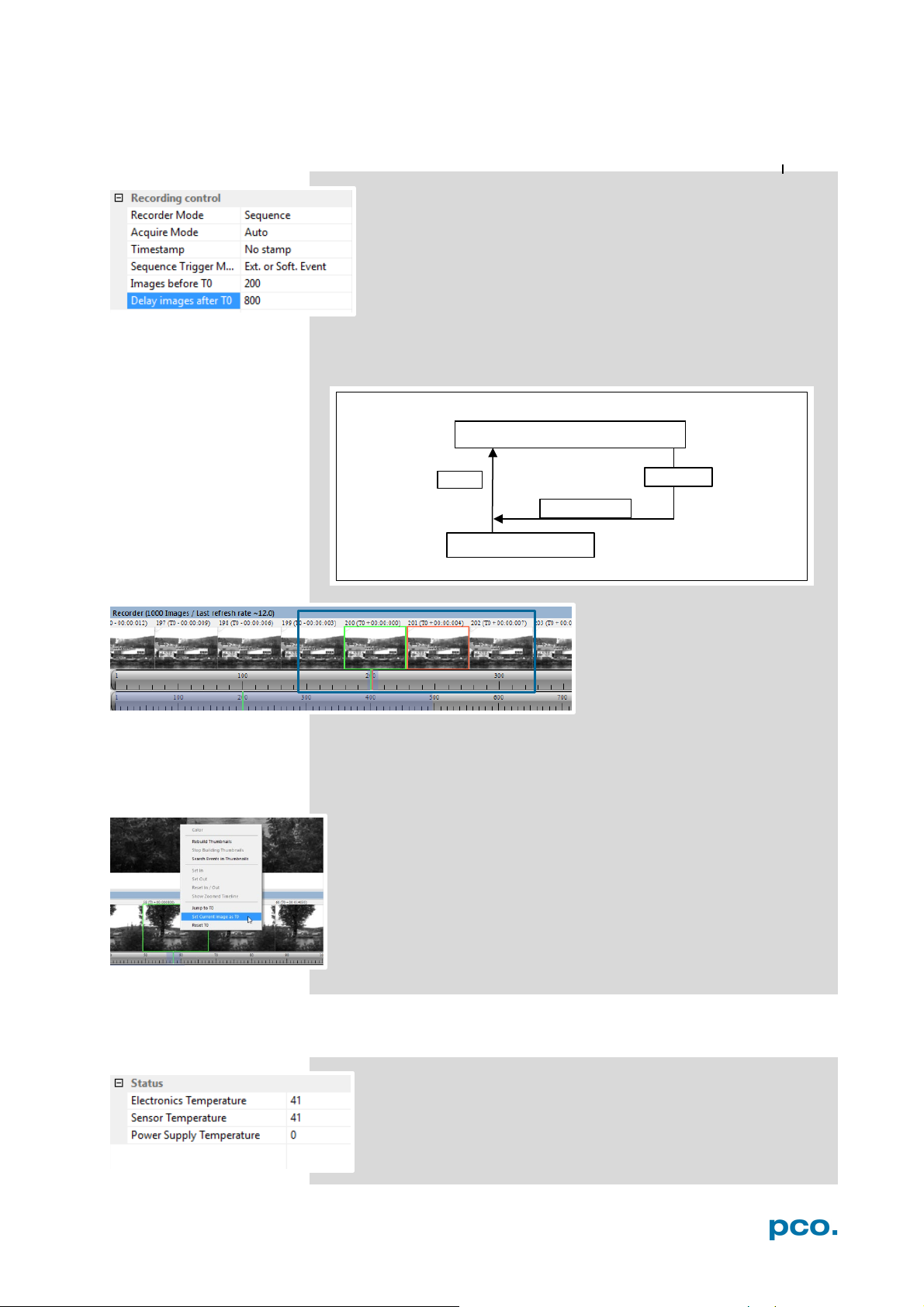
The relative position of the T0 trigger within the recorded
time window depends on the size of the RAM segment and
the delay images parameter. The following figure shows an
example, where the buffer size is 1000 images: The position
of the trigger is always calculated backwards from the end of
the buffer. The relation is always in terms of images.
In this context T0 is the point at which the sequence trigger is set
(at the BNC Trig In input).
After recording is finished
Recorder Images (see chapter
6.7) shows the thumbnail
images of the last recording:
Image T0 is framed in green,
the currently selected image in
All images before and after T0 are specifically marked, e.g. with 202
(T0 + 00:00:007). 202, in this case, corresponds to the image number
and its recording point in time after T0. The time stamp is divided into
min : s : ms.
Additional possibility to define T0: Right-click into the thumbnails
and Set Current Image as T0. Reset T0 erases this manually set
T0.
All Recorder Images features see 6.7.
orange.
6.3.6 STATUS
Shows the current temperature level of the pco.dimax cs
camera.
27
Page 28
1 2 3
Extension.
box
Breakout
cable
Type
Type
If checked on, a signal for
If checked on, a signal for
If checked on, a signal
Breakout cable
Extension box
Signal Type
Software I/O
Signal Type
Software I/O
Acq. Enbl.
(Trig In)
Seq. Trigger /
Acquire External
Exp. Trigger
(Sync In)
1
2
1 2 3
3
1
2
NOTICE
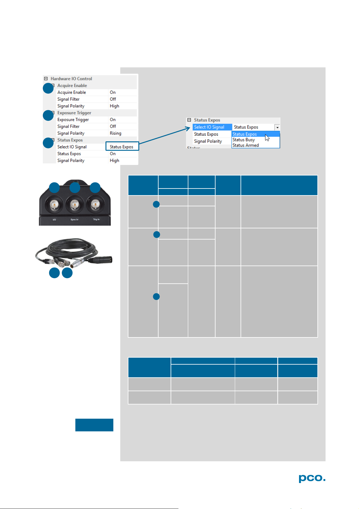
6.3.7 HARDWARE I/O CONTROL
Camware
Acquire
enable
Exposure
Trigger
Status
Exposure
Trig In Trig In
RS-485
TTL
Sync In Sync In
RS-485
TTL
I/O
TTL
RS-485
TTL/GND
RS-485
TTL
RS-485
TTL
n/a
Polarity Description
high/
low
rising /
falling
edge
high/
low
Acquire mode or Sequence
Trigger mode (see chapter
6.3.5) is accepted at the BNC
Trig In input
External Exp. Start or External
Exp. Ctrl trigger mode (see
chapter 6.3.1) is accepted at
the BNC Sync In input
indicating exposure status,
busy status or armed status
is given at the BNC I/O
output. Once an acceptable
trigger edge is received, busy
will be high. As soon as busy
is low again, a new trigger
edge is accepted. Status
armed is high till a T0 Trigger
is received.
Applied hardware signal type: CONTACT
BNC Input
Trigger Mode (Camware)
TTL RS-485
Ext. Exp. Start / Ctrl. TTL n/a
When working with Extension box make sure signal polarity is
inverted to a TTL signal type at the acquire enable (BNC Trig In) input.
BNC sockets see chapter A3.2 Extension Box.
28
Page 29
6 CAMWARE 4 SOFTWARE
Type
Explanation
RS-485
Receiver sensitivity: ±200 mV
TTL
Maximum low level: 0.8 V
Minimum high level: 2 V
Contact
Maximum switch on resistance: 100 Ohms
Minimum switch current rating: 1 mA
BNC Sync In
BNC I/O
Exp Stat (out)
BNC I/O
t
readout
Not accepted
NOTICE
Filter: electrical interference filters (off, medium, high). An active filter
causes an internal signal delay.
Polarity: active for high/low signal or rising / falling edge
Acquire Mode : external (Signal Type Contact)
Polarity high: if signal is high / contact is open, camera captures
images;
Polarity low: if signal is low / contact is closed, camera captures
images.
Sequence Trigger Mode: Ext. or Soft. Event
Polarity high: if signal is high / contact is open, camera keeps
recording images
Polarity low: if signal is low / contact is closed, camera stops
recording images immediately or when Delay Images after T0 trigger
event have been recorded
Note: termination of 120 Ohms outside camera required
Minimum switch off resistance: 40 kOhms
Minimum switch voltage rating: 5 VDC
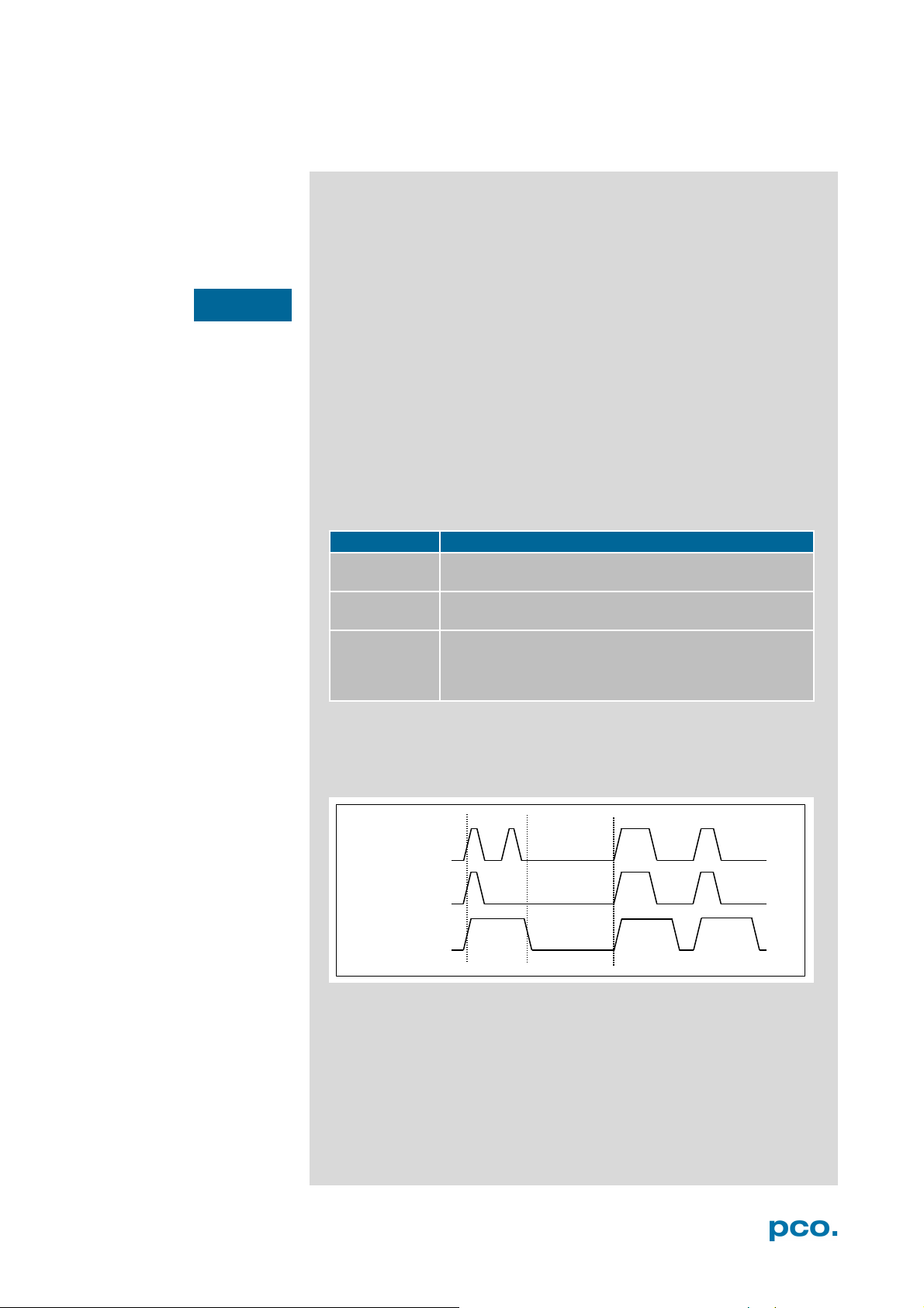
This graph shows the output signals Exp. Stat and Busy Stat of the
pco.dimax cs camera in Ext. Exp. Start / Ext. Exp. Ctrl mode (see
6.3.5) after an exposure trigger signal is received:
Busy Stat (out)
BNC Sync In: the second trigger is not accepted, because the
camera is still in readout mode → see Busy Status t
readout
.
29
Page 30
1
2
3
4
1 2 3
4
6.3.8 CONVERT CONTROL
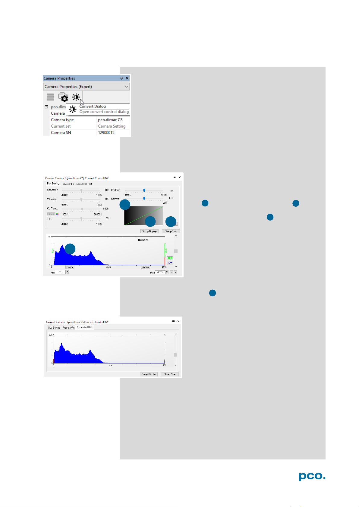
Start the Convert Control Dialog with the Black/White Button in
Camera Properties.
Convert Control BW
The display of the original 12 bit image intensity values (x-axis) in the
shown 8 bit values (y-axis) can be arranged.
BW Settings (includes histogram of original
data)
It is possible to hide the histogram of original
data and to switch tab/histogram .
Green sliders in histogram
left slider = Min controller (corresponds to
value 0 of the 8 bit display). Values below that
mark are set to 0, i.e. displayed as black.
right slider = Max controller (corresponds to
value 255). Values above that mark are set to
255, i.e. displayed as white.
The values in-between are converted into a
value between 0 and 255 according to Contrast and Gamma
settings. See the small graph reflects the calculation.
Proc config tab: see under Convert Control Color
Converted Hist
Tab shows the histogram of converted data.
Other functions (Saturation, Vibrancy, Col.Temp, Tint) are inactive
for monochrome cameras
30
Page 31
6 CAMWARE 4 SOFTWARE
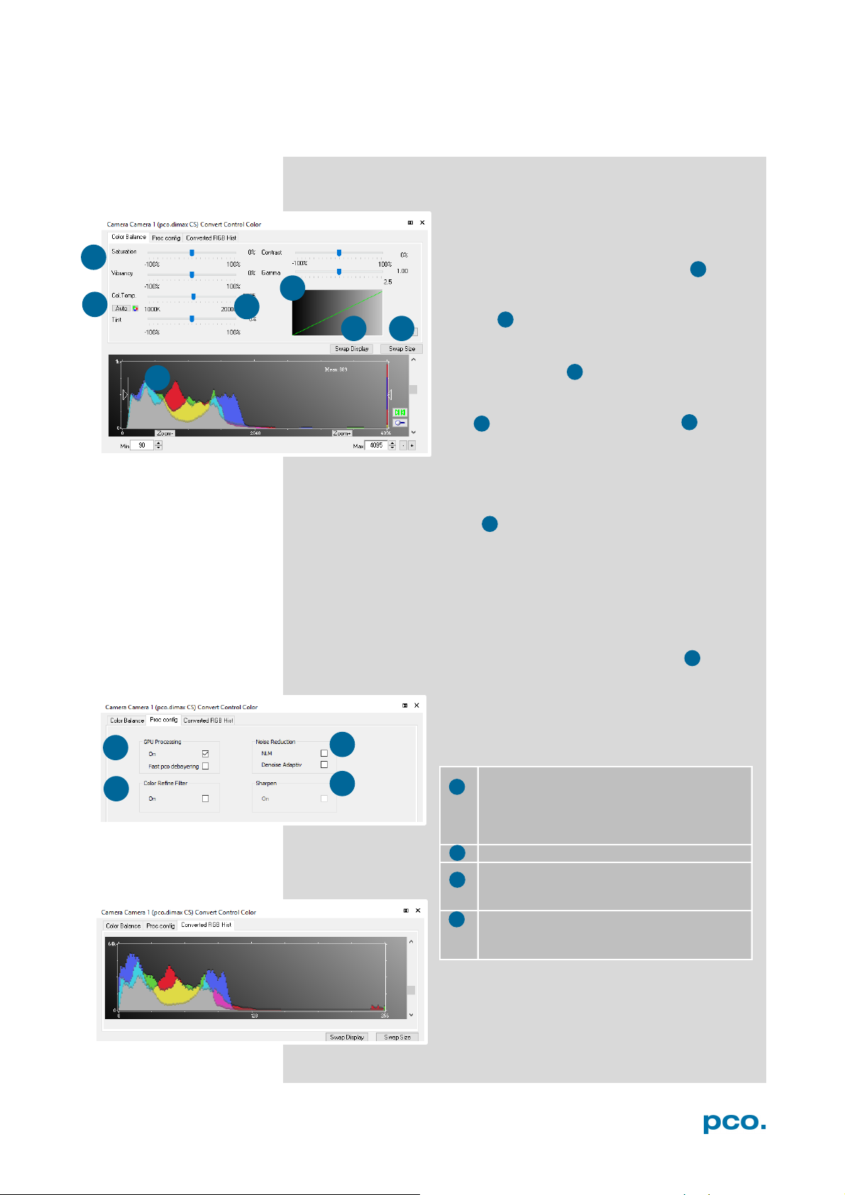
GPU Processing
Color Refine Filter only color cameras
Noise Reduction
Denoise Adaptive: only color cameras
Sharpen:
pco debayering)
1 2 3 4 5 6 7
1 2 3 4 5 6 7
1 3 4
2
1 3 4
2
Convert Control Color (only pco.dimax cs color)
Color Balance (Histogram of original data)
Intensity of single color of a single color is
controlled by Saturation and Vibrance
Press the Auto button to set the white
balance
.
The balancing of RGB is controlled by
Col.Temp and Tint
.
It is possible to
hide the histogram of original
data and to switch tab/histogram .
The user can influence how the 12 bit intensity values of the original
image are displayed in 8 bit values in different ways.
White sliders in histogram
left slider = Min controller (corresponds to value 0 of the 8 bit
display). Values below that mark are set to 0, i.e. displayed as no
color.
right slider = Max controller (corresponds to value 255). Values
above that mark are set to 255, i.e. displayed as full color.
The values in-between are converted into a value between 0 and 255
according to Contrast and Gamma settings. The small graph
reflects the calculation.
Proc. Config (Process configuration)
Due to proprietary high-end algorithms used for
these image processing features, no detailed
description is given here.
.
On: Switch on in order to significantly reduce
processing time (increases refresh rate of the
live image
Fast pco debayering: only color cameras
NLM: Non local means algorithm
On: only color cameras (first activate Fast
Converted Hist
This tab shows the histogram of converted
data.
31
Page 32
6
7
1
2 2 5
6
5
7
1
NOTE
3
4
3
4
6.4 IMAGE OVERLAY
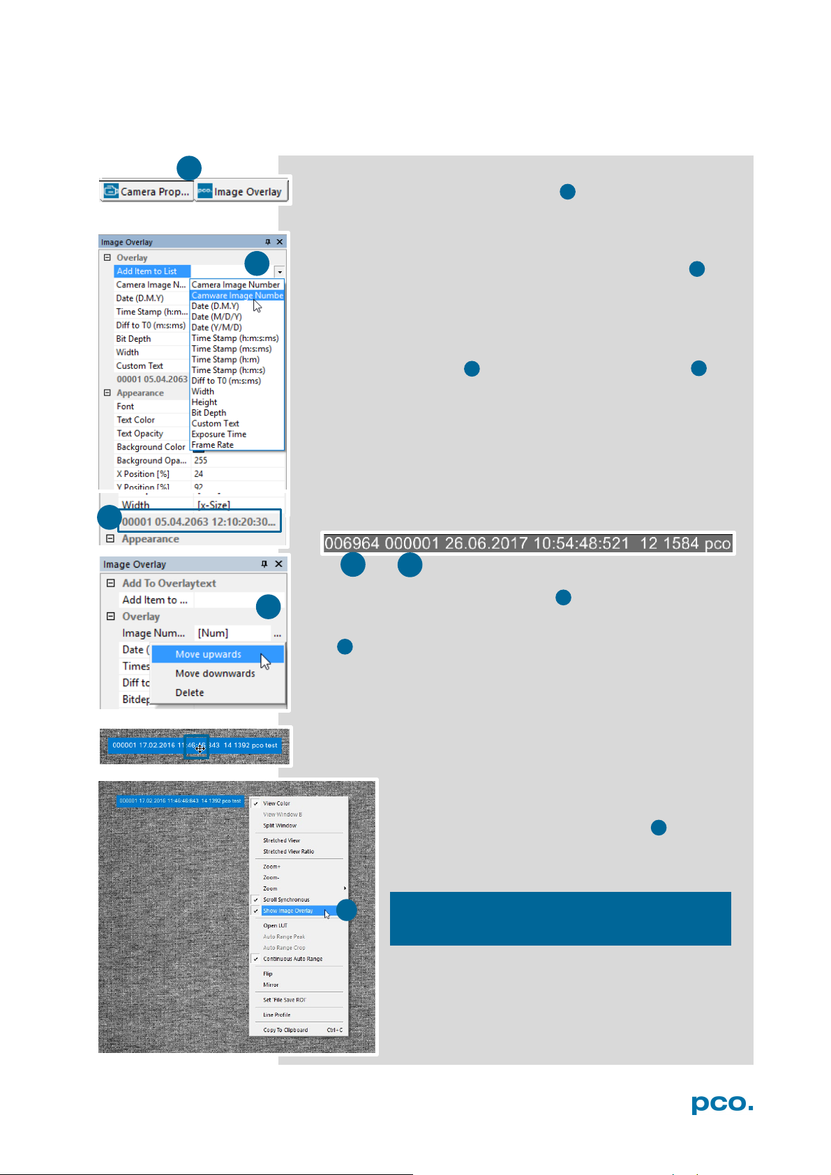
Open Image Overlay: these two buttons allow easy switch between
Camera Properties and Image Overlay.
If not available, see 6.9.5 View Menu to activate this menu.
This function enables an individually configurable image overlay
allowing to display information within the images.
Many different options are available by clicking Add item to…
Also the Appearance is configurable:
Font, Text color, Text opacity, Background color, Background
opacity and horizontal or vertical orientation.
Camera image number and Camware Image Number are
two different count methods:
Camera image number: the image numbers are incremented
continuously. When recording in Ring Buffer mode, the image
numbers exceed the number of images stored in the RAM memory
of the computer since images are overwritten when the memory is
full, starting with the first image in loop.
Camware image number: the software displays the image numbers
according to the number of images being recorded (starting with
image 1).
A preview of the image overlay is shown.
Each item can be moved upwards, downwards or deleted by clicking
on …
By drag & drop the Image Overlay can be moved easily to your
favorite position within an image.
Right click in the image window to turn on Show
Image Overlay and activate this function.
This function does not overwrite image data.
32
Page 33
6 CAMWARE 4 SOFTWARE
1
2
1
2
6.5 RECORDER TOOLS
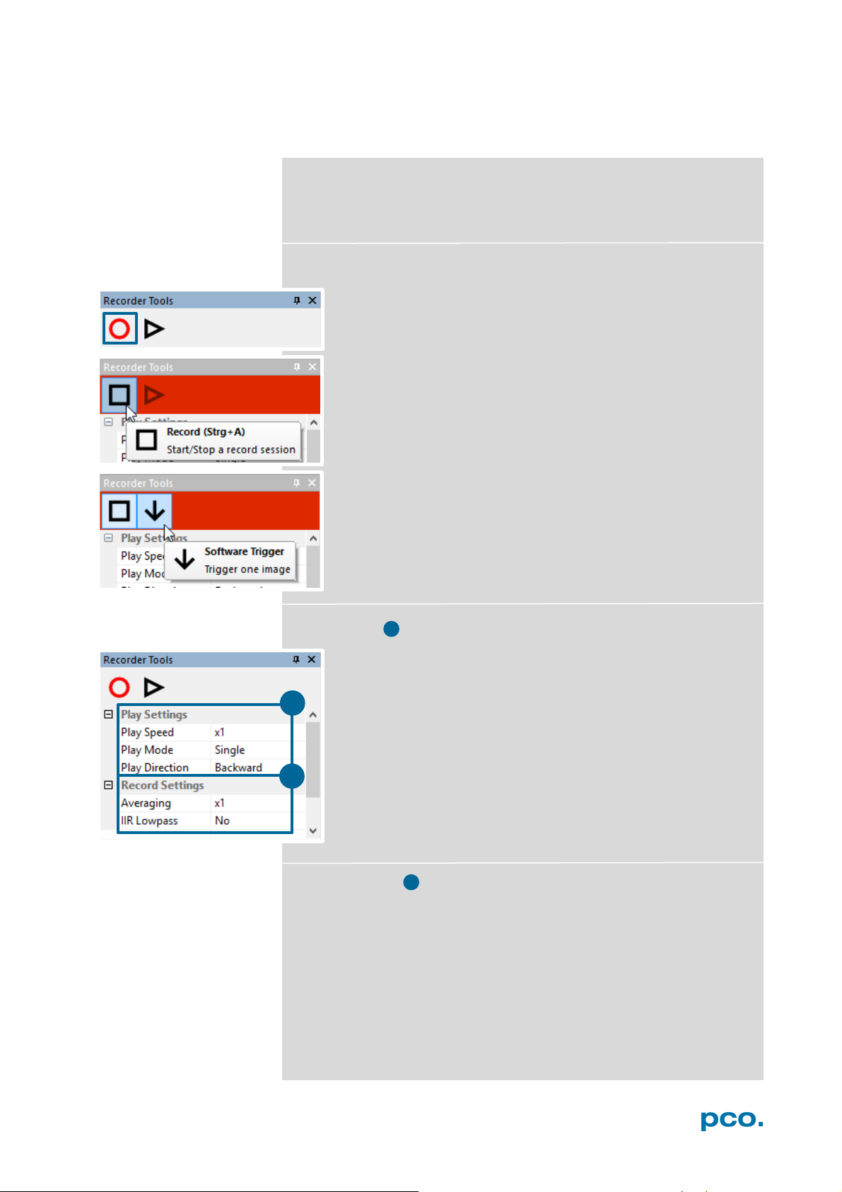
Recorder Tools provides Record and Play function, Play Settings
and Record Settings.
Located on the right lower side of Camware or, if closed, activated by
View Menu (see chapter 6.9.5)
Record
Play Settings
Start/Stop record with Record Button.
or press enter in the View window to start or stop recording.
Record: in record state Camware software is highlighted in red.
Exposure time may be changed during recording. See 6.3
Camera Properties.
Software Trigger Mode: after record is started an arrow
pointing downwards appears. Clicking on it triggers a single
image. (see 6.3.1).
Play Speed: selectable play speed from x1 to x256 or from 1fps
to 16 fps. E.g. in mode x1 a recording with 1000 fps is played
with 25 fps.
1 fps means that only one frame per second is played.
Play Mode: selectable play mode of the recorder (continuous or
one-time (re)play).
Play Direction: selectable direction of record play (forward or
backward)
Record Settings
Averaging: averaging images in the buffer reduces statistically
independent (image) noise. Set a value higher than x1 in the dropdown list and this number of images will be averaged.
IIR Lowpass: another option to reduce the noise is the activation of
the Infinite impulse response IIR lowpass filter. This filter takes
90% of the previous image and 10% of the new image to create
images with clearly reduced noise.
Image (actual) = Image (act - 1) * 0.9 + Image (new) * 0.1
33
Page 34
3
1
3
1
2
3
2
3
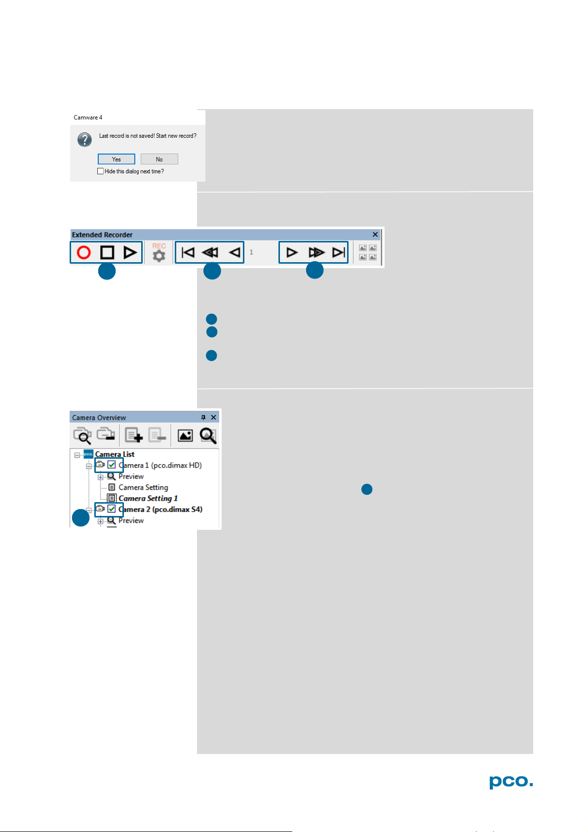
Reminder dialog
If you made a recording but did not save it yet, Camware will remind
you to save the record before starting a new one.
Extended Recorder can be activated (see 6.9.5)
Functions:
• Start & Stop record / Stop record / Replay
• First image (jump to first image) / Back fast (jump backward) /
Back (jump one image backward)
• Forward (jump one image forward) / Forward fast (jump forward) /
Last image (jump to last image in record)
Recording with multiple cameras
With all cameras activated recording is started simultaneously for
all cameras.
Recorder will use Recorder mode settings (Sequence or Ring
Buffer) of the selected camera for all cameras (see 6.3.8)
For single camera recording, deactivate cameras by removing
the check mark from the box.
34
Page 35
6 CAMWARE 4 SOFTWARE
1 2 4 5 3
1
2
3
6
4
5
6
6.6 VIEW WINDOW
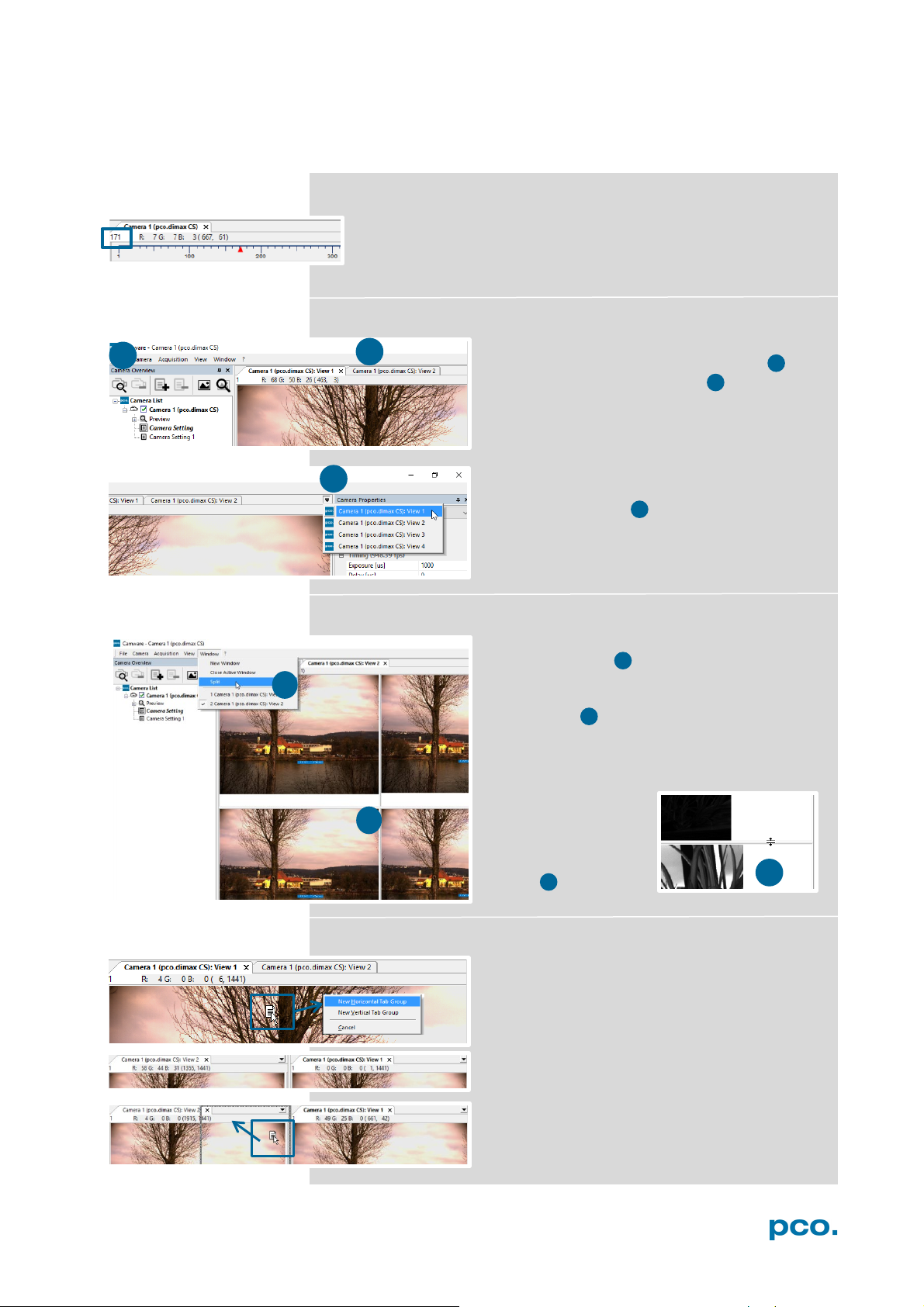
Quick-scroll through images
Having recorded at least 50 images, you can scroll through the
images quickly. To do this, hold down the left mouse button on
the image number. Additionally you can enter the desired image
number directly into the number field.
More View Windows
You may open more than one window for one
camera: just click on new view window 1 and
Camware will create a new one 2 .
Even when multiple view windows (or from
multiple cameras) are open, the same image
number is always shown in all of the view
windows.
A dropdown menu helps to select a view
window. If there are more view windows than
can be displayed on the desktop, you may
select individual view windows.
Split View Window
The view window can be split. Choose
Window → Split 4 and a split cross will be
shown. The size of splitted window elements is
easily adjusted by grabbing and dragging the
dividing lines 5 .
The main reason for this function is to view four
sections of the image in one view. Choose the
Zoom± function to zoom in the image (first turn
off Stretched View)
(See 6.9.8)
To undo the split,
double click on the
dividing line (after
symbol 6 is visible.
Two Tabs side by side or on top of each other
To view two tabs side by side or arranged one
above the other just drag a tab and Camware
will ask you whether you want to create a new
horizontal or vertical tab group. Undo this by
draging the tab back to its former position.
This also applies for view windows of several
cameras.
35
Page 36
1 1 2
2
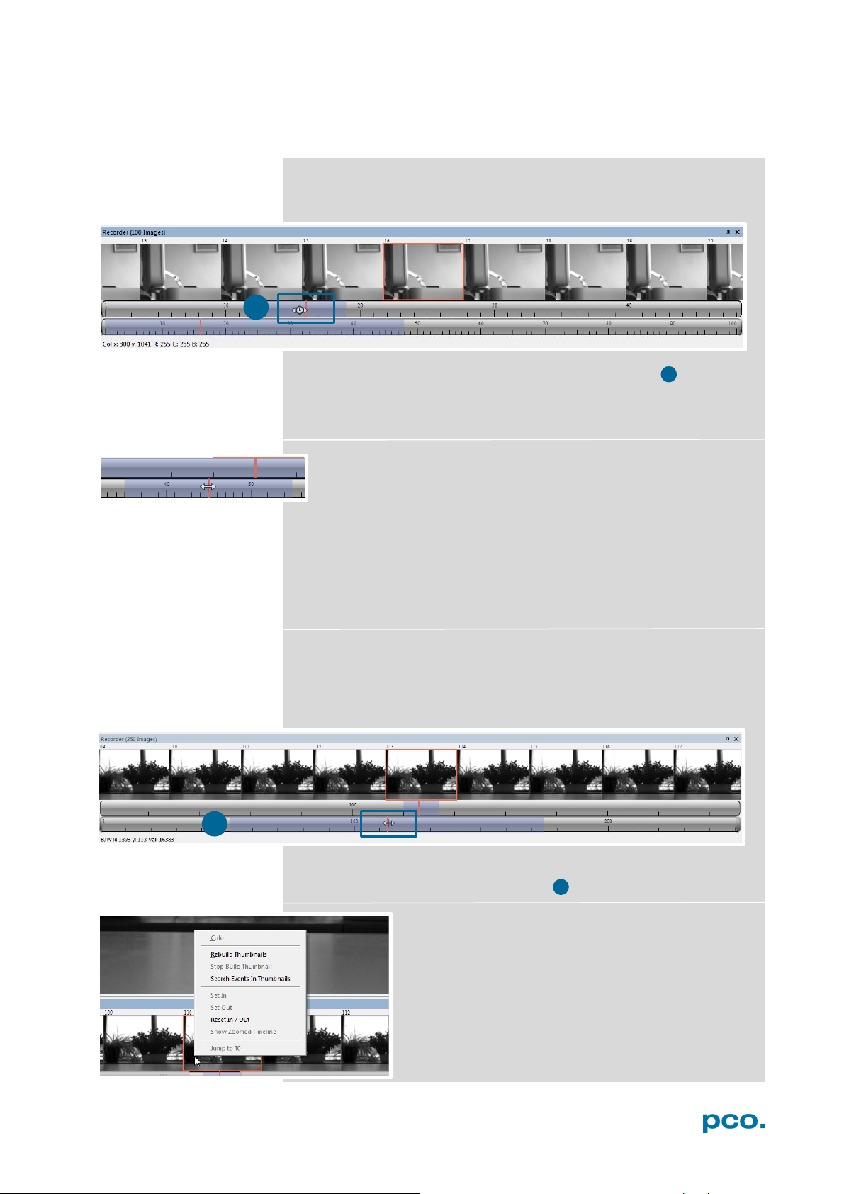
6.7 RECORDER (IMAGES)
When recording is done, small preview images (thumbnails) are built
and displayed automatically. This will take some time depending on
the performance of your computer system.
Clicking (left mouse button) within the upper scale bar 1 , you can
adjust the number of images which are shown by moving the mouse
left or right. Minimum is 20 and maximum is half of the recorded
images in this scale.
Quick scrolling: scroll through the thumbnails by dragging the
orange bar with the mouse or by mouse wheel while the cursor is
over the image number bar.
While quick scrolling, Preview window displays the active image
sequence. This allows to quickly scroll through the image sequence
displaying the live images in the Preview window forwards or
backwards. The View window will not actively show live images
during quick scrolling (only in normal scrolling speed by mousewheel).
Clicking on a thumbnail image it will be shown on the view window.
Scroll via mouse wheel through the thumbnails.
The upper blue bar refers to the number of displayed thumbnails.
The lower blue bar shows the range of the upper scale in relation to
the whole record.
The second scale shows the total number of recorded images. It
allows fast scrolling through the images 2 .
Right-click menu (click on thumbnails)
Allows to rebuild all thumbnails and to search for
events.
Furthermore the Set In / Out enables to set values
for a sequence, which can be played via play button.
Reset In / Out discards these settings.
Set In / Out is active: if you save/export your
images, only the selected ones are saved/exported
(see 6.9.2).
36
Page 37
6 CAMWARE 4 SOFTWARE
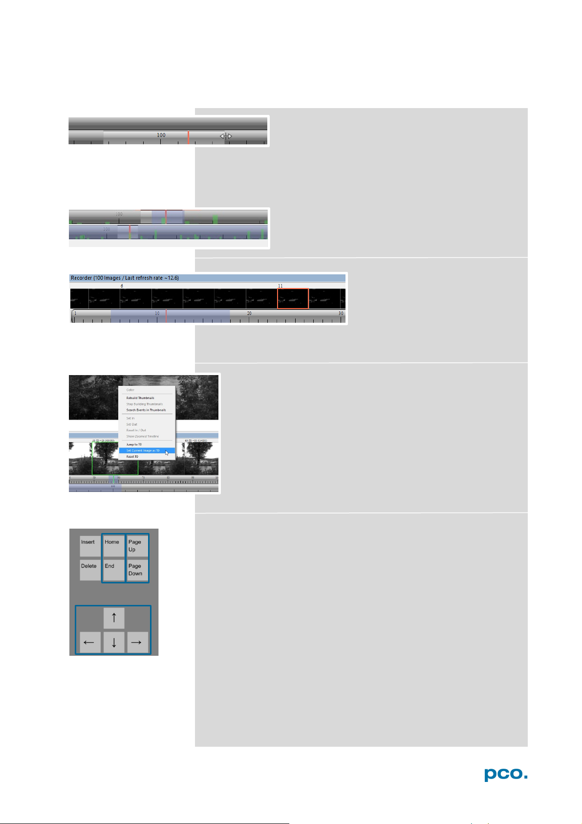
The light gray area in the upper scale shows an InOut example area. To define a new area: just right-
click on the start and end frame in one of the
scales. The In image must be left to the red bar, the Out image to the
right of the red bar.
Adjust the In / Out area by holding down the left mouse button and
slide the boarders to increase / decrease.
Search Events in Thumbnails: detected events are
displayed as green bars.
Too dark or bright thumbnails
If thumbnails are too dark or too
bright, right-click in view window
(see 6.9.8) and select Auto Range
Peak or Auto Range Crop. Then
right-click on a thumbnail image and select Rebuild Thumbnails.
Now the thumbnail images should conform to the view window.
Set current Image as T0
It is possible to set a T0 Image manually. For information about
T0, see Sequence Trigger Mode in chapter 6.3.5 .This T0
Image can be resetted.
Use your keyboard to scroll through the Images
Page up / down keys: 10 Images up or down
Arrow keys: quick scrolling through the images. Advantage: fluent
video playback in the View window (forwards or backwards).
Home/Pos1 key: first image.
End key: last image.
37
Page 38
4 5 6 7 8 9 1
2
3
11
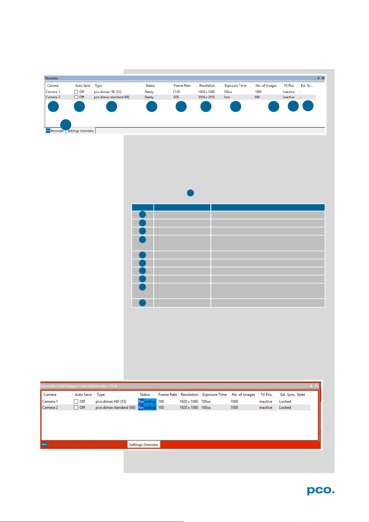
No.
Function
Description
Camera name
Name
Auto Save
Off , Unconfigured (red), OK (green)
Type
Camera type and serial number
Status
Ready or Recording
Frame Rate
Currently selected frame rate
Resolution
Resolution in pixels
Exposure Time
Selected exposure time
Number of Images
Number of images to be recorded
T0 Position
See T0 chapter Fehler! Verweisquelle
Ext. Sync. State
Status: Locked or -
1
11
3 4 5
6
7
8
9
10
2
10
6.8 SETTINGS OVERVIEW
Settings overview shows the most important parameters of your
camera(s) at a glance. For more than one camera connected, each
camera and its parameters are listed.
The parameters can only be changed under 6.3 Camera Properties.
Switch easily between the Recorder (Images) section and the
Settings Overview.
Green background: Images are in memory
konnte nicht gefunden werden.
Ext. Sync State is only available if the Trigger Mode of the camera
is set to External Synchronized (see 6.3.1), that means the
recording of the cameras is externally synchronized. It takes up to
30s until the synchronization is completed and Locked is displayed.
This function will not display a Master / Slave synchronization.
“-“ means not synchronized (Ext. Sync Mode activated /
deactivated).
38
Page 39
6 CAMWARE 4 SOFTWARE
6.8.1 AUTO SAVE
Auto Save helps to save your recorded images or sequences in an
easy way. There is no need to save each image / sequence
separately from each connected camera. Therefore this function is
very useful if you use more than one camera. Once configured Auto
Save allows acquiring and saving as many images / sequences as
needed during your experiment. This function can store RAW (e.g.
TIFF) and Export file types (e.g. AVI, JPG)
For standard file save see File Menu 6.9.2.
Explanations will be displayed in the Info Text window at the bottom
of the menu.
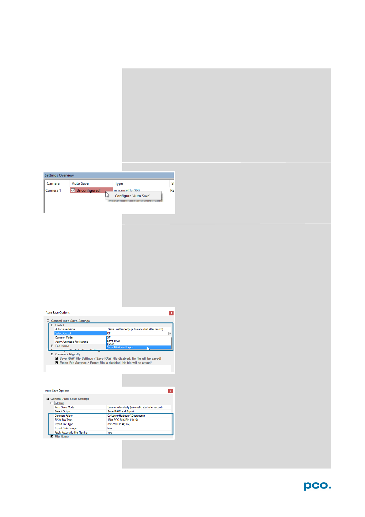
Enable Auto Save by clicking on the check box.
The text changes to Unconfigured! (red
background).
Right-click on the Unconfigured! field and click on
Configure ‘Auto Save’.The Auto Save Options
dialog is displayed.
First, configure the General Auto Save Settings - Global
Auto Save Mode: two different modes are available, Save manually
and Save unattendedly.
The Save manually mode allows to store RAW images and export
images after recording a session, when hitting the SHIFT and A keys.
This allows to cut the image sequence before saving.
The Save unattendedly mode downloads all RAW images and
exports the complete image sequences of all cameras immediately
after an active recording is stopped.
Select Output:
Off – Auto Save is deactivated
Save RAW – Only 16 bit RAW files are stored (b16,
pcoraw, MultiTif-File, Tiff
Export – only compressed files are stored (BMP,
JPG, Tiff, AVI, MPEG, WMV)
Save RAW and Export – RAW and Export files are
stored simultaneously
Common Folder: main folder for stored files
RAW and Export file Type: select the type of RAW
and Export file
Export Color Image: select to export color images
(only for color cameras)
Apply Automatic File Naming: if set to yes, stored
files are automatically named by Camware.
39
Page 40
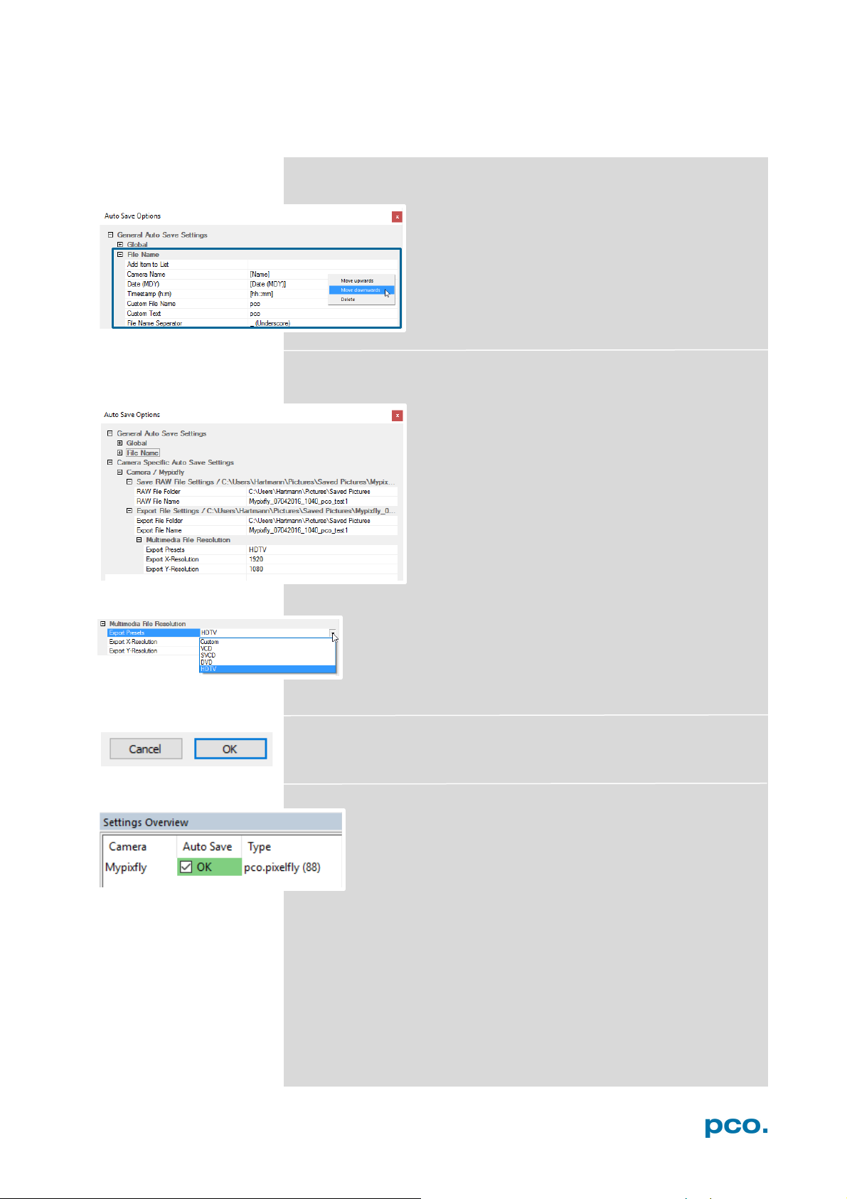
General Auto Save Settings – File name
Set your file name individually by adding or deleting
items. Position these elements as needed.
Camera Specific Auto Save Settings:
Configure camera specific settings for each
connected camera.
Save RAW File Settings: set RAW File Folder and
RAW File Name.
Export File Settings: set Export File Folder and
Export File Name.
Multimedia File Resolution: set predefined video export
resolution or enter a Custom x- and y-resolution.
Finish the configuration by clicking OK.
After configuration is finished, Auto Save status turns OK
(highlighted)
40
Page 41
6 CAMWARE 4 SOFTWARE
6.9 CAMWARE FEATURES
This chapter describes in detail the Camware Demo Mode and the
File, Camera, Acquisition, View and Window menus.
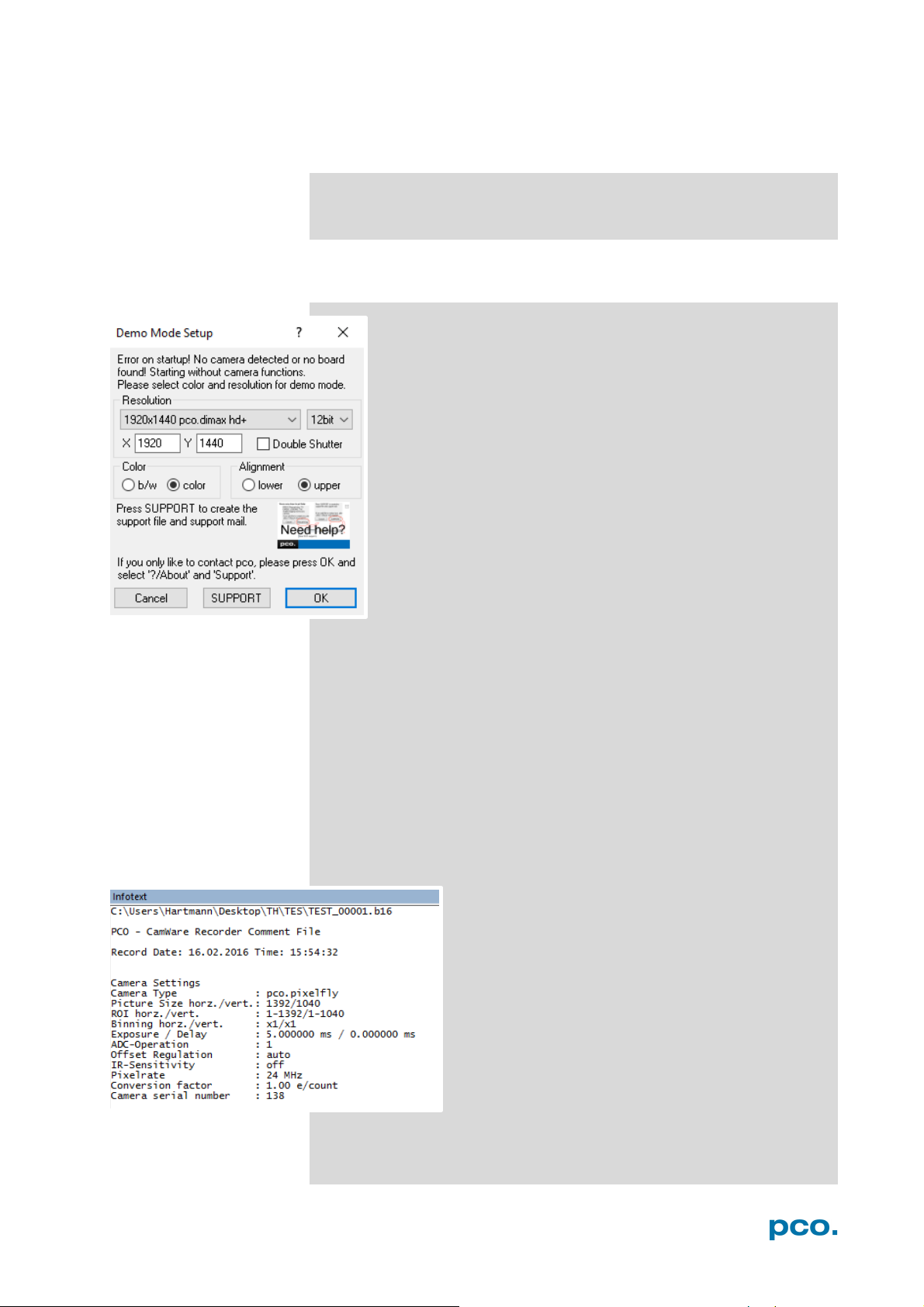
6.9.1 DEMO MODE
Upon start Camware, it automatically recognizes the camera
type of the connected and running cameras.
Camware starts in Demo Mode, if your camera is switched off
or no camera is connected.
In this mode all image processing features are available, but
all camera settings are deactivated. Just tell Camware the
type of image you want to open. For that purpose, the Demo
Mode Setup window opens and asks for the corresponding
input.
Need Help? Having troubles to run the camera, this window
will pop up. See instruction in appendix A7.
Resolution
The drop down list displays the image sensor spatial resolutions of all
PCO camera systems. Select the specific resolution and bit depth of
the images to be opened! Double Shutter mode should be ticked if
such images have been recorded.
Color
With the radio buttons, the user can specify whether the image type
is monochrome (b/w) or color.
Alignment
Select between MSB (most significant bit) upper alignment and LSB
(least significant bit) lower alignment to display stored images.
Infotext
The Infotext is automatically shown in Camware if
you open a stored raw sequence.
The Camera Properties settings, storing location
and Record date are listed in this file.
This text file is saved with every recorded raw
sequence / image. Camware asks you for custom
text before your images are saved. You can add
information, e.g. lens and aperture of your
experiment.
Infotext can be activated in the View Menu 6.9.5 at
any time.
41
Page 42
NOTE
e aware of the
different storage
formats, for example
the bitmap
stores 8 bit
therefore the image
content of a 16 bit
image is reduced, if
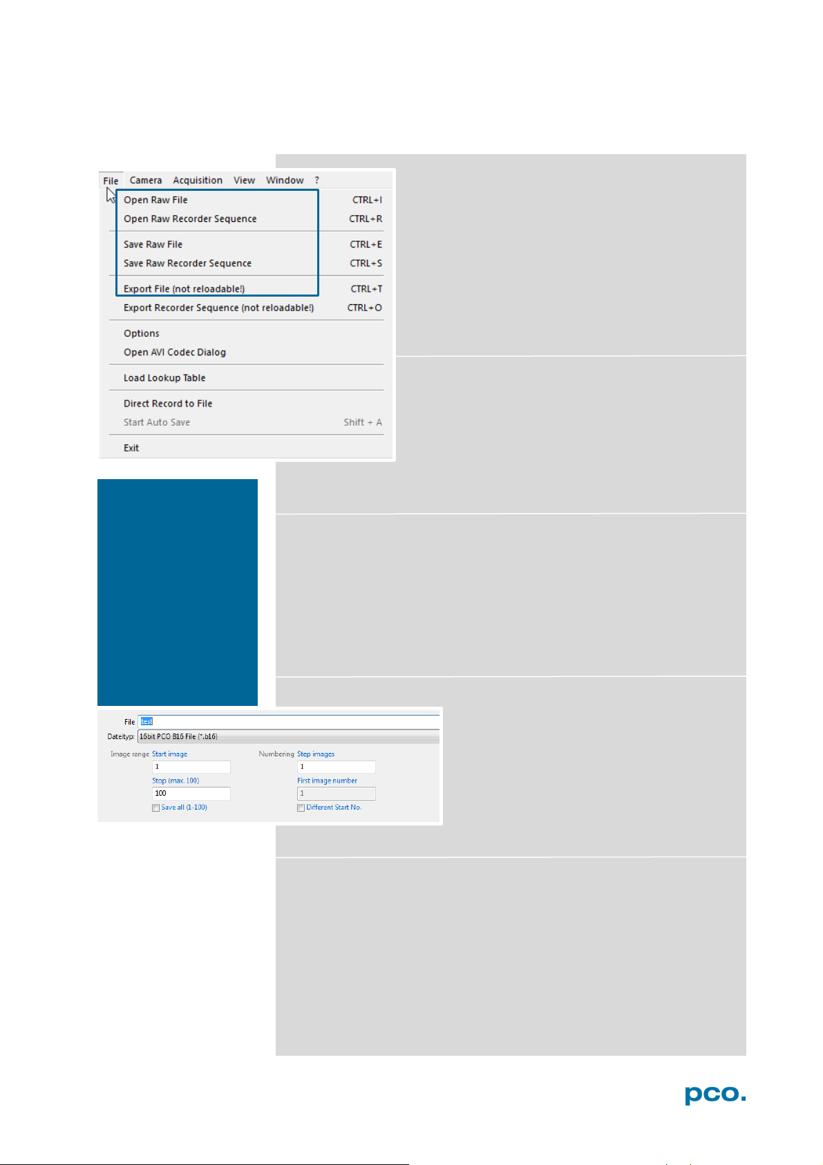
6.9.2 FILE MENU
B
characteristics of the
*.bmp format
values only and
stored as bitmap.
Open RAW File (single image only)
This command imports a single image into the
active image window. Only files with the extension
and format *.b16 (=PCO proprietary binary image
format) and *.tif (16 bit TIFF image format) can be
imported. If the recorder is enabled, each imported
image is transferred to the buffer shown in the
picture number. The image itself is fitted to the
current image size. If the recorder is disabled, the
current image size is set to the parameters of the
imported image.
Open RAW Recorder Sequence (image sequence
from one camera)
Imports a sequence of images. If more than one
camera is connected and an image window is
currently open, the sequence is loaded to the
active window. If no image window is open, the
images are loaded to camera #1. This command
opens the Open file dialog box. Only files with the extension and
format *.b16, *.pcoraw, *.tif and multi tif can be imported.
Save RAW File (single image only)
Saves the image displayed in the active window and opens the Save
file dialog. The image file can be saved in 16bit *.b16 and *.tif format.
If more than one camera is connected, save all current images by
selecting Export all images in the Save file dialog box. This feature
saves one image of each active camera in one step (it is not
necessary to repeat the save process for each camera). The Save
command is not available if no image window is open. For Auto File
Save see 6.8.1
Save RAW Recorder Sequence (image sequence from one camera)
Save Recorder saves or exports image
sequences. If more than one camera is
connected and an image window is
currently open, the record of the active
window will be saved. The command opens
the Save recorder file dialog box. It is
possible to select the number of saved
images, to step images and to choose the
first image number. For Auto File Save see 6.8.1
Export File (not reloadable!)
Exports the image of the active image window. This command opens
the Export Image dialog box. Files with the extensions fts, tif, bmp,
asc, jpg, and jp2 can be exported. This topic is not visible, if no
image window is open. For Auto File Save see 6.8.1
42
Page 43
6 CAMWARE 4 SOFTWARE
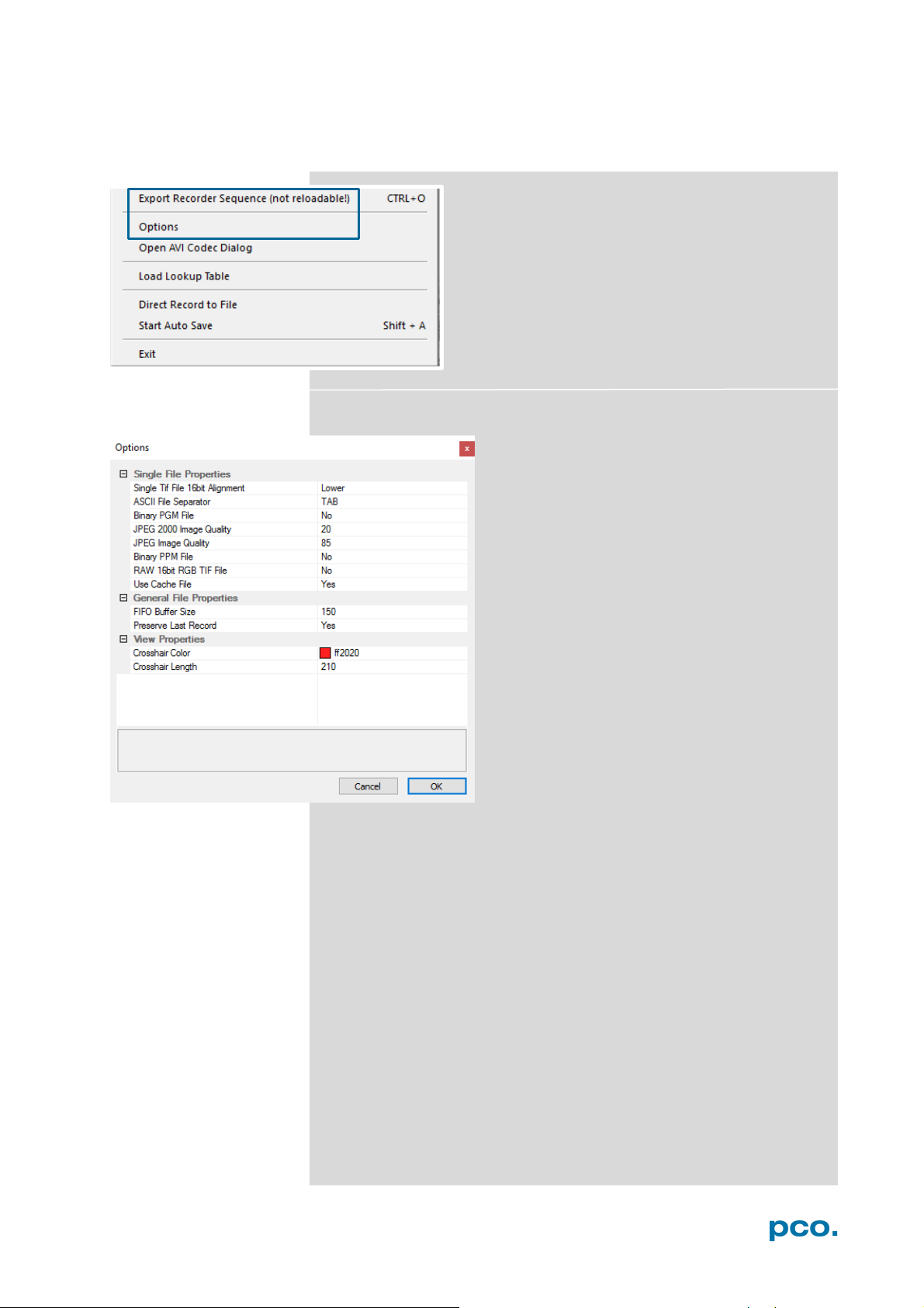
Export Recorder Sequence (not reloadable!)
Exports a sequence of images. If more than one
camera is connected the image record of the
currently open window will be saved. If no image
window is open the Export Recorder Sequence
menu does not appear. This command opens the
Export recorder box. Files with the extensions fts,
tif, bmp, asc, avi, mpg, jpg, jp2, and wmv can be
exported (see Appendix A6). For Auto File Save
see 6.8.1
Options
Single File Properties
Single tif file 16 bit alignment: upper / lower
ASCII File Separator: select a separator for
the values in the ASCII file. Select tab, space,
semicolon, colon, comma, hyphen, slash or
backslash.
Binary pgm file: set the format of the pgm
(portable gray map) file. Select: yes, no.
Jpeg2000 image quality: set compression
from 20 to 100%.
Jpeg image quality: set compression from 20
to 100%.
Binary ppm file: set format of the ppm
(portable pixmap) file. Select: yes, no
RAW 16bit RGB tif file: save raw tif without
color balance. Select: yes, no.
Use cache file: Caches image data on disc for
a camera with camera internal memory. Select:
yes, no
General File Properties
FIFO buffer size: set the FIFO buffer size in number of images. This
avoids gaps during file write delays. Usually it is set to 150.
Preserve last record: preserves current recorded images. When set,
the user will be asked whether to really start a new record or to close.
View Properties:
Crosshair color: set crosshair color, save ROI and line tool.
Crosshair length: set the crosshair length in pixel.
Activate crosshair: see chapter 6.9.8
43
Page 44
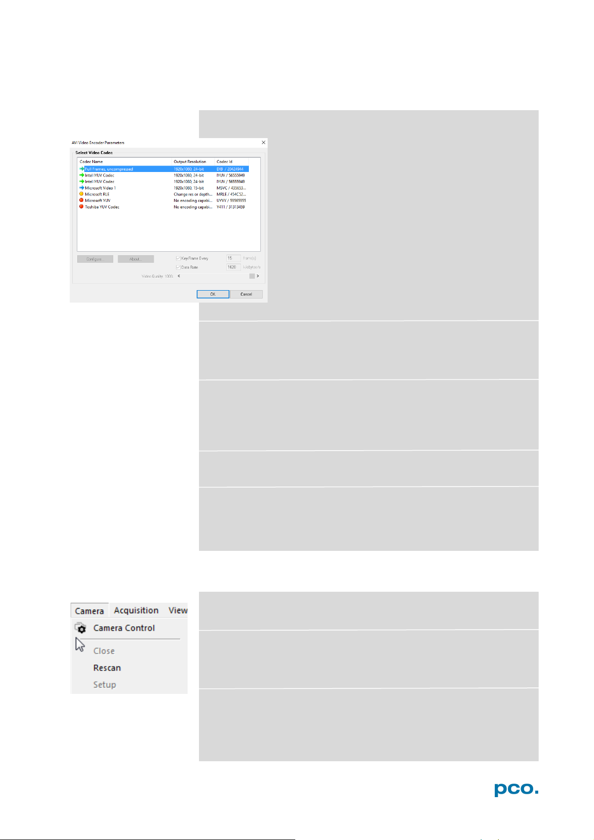
Open AVI Codec Dialog
Using Auto File Save 6.8.1 and selecting AVI for video
output affects stored video sequences.
Only available, if AVI video format is selected.
Select the (compression) codec you want to use for
stored sequences. All installed codecs are listed here.
Load lookup Table (for monochrome cameras)
This feature assigns pseudo colors (Lookup-Table LUT) to a
monochrome image. Either select one of the four predefined or create
your own. The result is shown in the color view window.
Direct Record to File
Preset a certain number of images to be stored. If the camera
captures images faster than the computer can save to disk, you will
lose images. Images display doesn't interfere with the record
process.
Start Auto Save
Only available, if Auto Save is activated, see 6.8.1
Exit
Exits the program and closes all channel dialog windows. Window
positions, settings and sizes are stored in the windows registry and
will be loaded again at next start-up.
6.9.3 CAMERA MENU
Camera Control
Opens the camera control window (see 6.3).
Close
Disconnects camera and switches Camware to Demo Mode. In case
of multiple cameras, all cameras must be closed for Camware to
switch to Demo Mode.
Rescan Disconnects and reconnects all cameras.
44
Page 45
6 CAMWARE 4 SOFTWARE
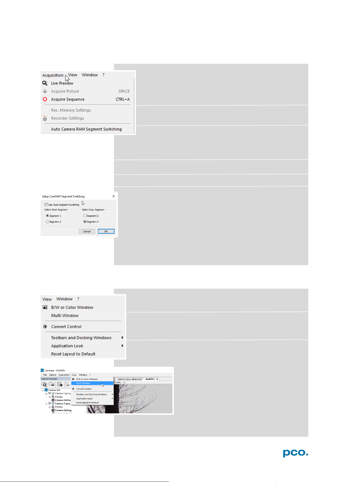
6.9.4 ACQUISITION MENU
Live Preview
Live Preview for fast and easy adjusting and focusing of the
camera. The active window will be updated. To see another
window, simply click on the window. This option is not
available in double shutter mode.
Acquire Picture
Active if Recorder Mode is set to Soft Trigger, see 6.3.1
Acquire Sequence
Starts recording images into the system memory according to Trigger
Mode selection (see 6.3.1). During recording, all camera controls are
locked.
Rec. Memory Settings (not available)
Recorder Settings (not available)
Auto Camera RAM Segment Switching
Records automatically in two or three different camera RAM
segments one after another resulting in two or three separate image
sequences.
If Recorder Mode is set to Sequence and the set number of images
is achieved the RAM segment switches automatically to the next
segment and stops after the last segment is full.
If Recorder Mode is set to Ring Buffer a stop trigger must stop the
active record into the dedicated segment. A new record starts
automatically into the next segment.
6.9.5 VIEW MENU
B/W or Color Window
Opens a new display window.
Convert Control
See chapter 6.3.8.
Multi window
View the images of all active cameras in
consecutive order in one window. It provides
an easy comparison of the views of different
cameras.
Use the same ROI and timing settings for all
cameras.
Only available when using more than one camera and only after a
complete sequence is recorded (sequence mode) or after buffer is full
for the first time (Ring Buffer).
45
Page 46
2
3 5 1
4
1
2 3 4
5 6 6
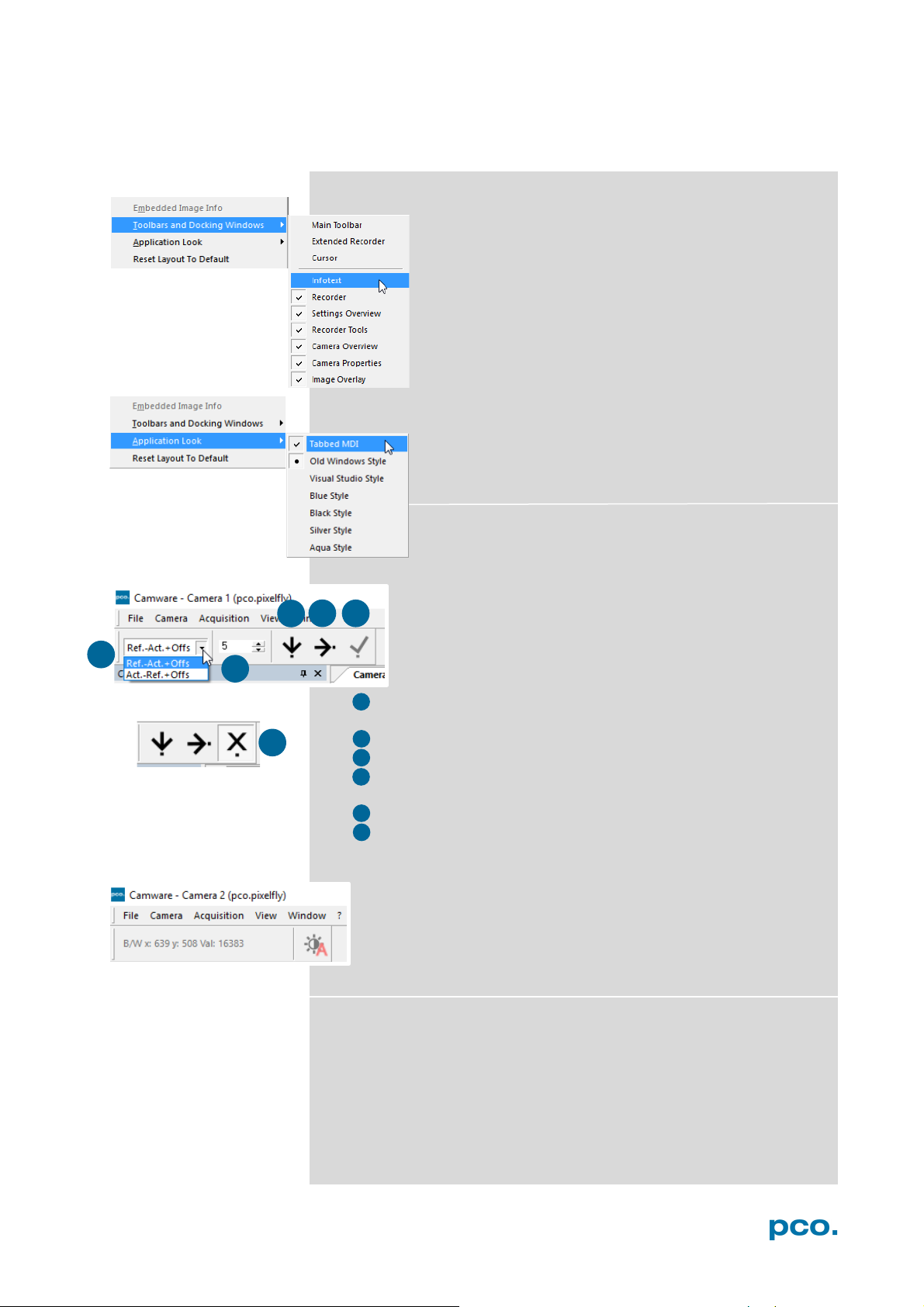
Toolbars and Docking Windows
Standard toolbars of Camware 4 are Recorder/
Recorder Tools / Camera Overview / Camera Properties
and Image Overlay. Additional Toolbars known from
Camware 3.x are displayable, but not essentially
needed: Main Toolbar / Extended Recorder / Cursor.
For function Infotext see 6.9.1.
Application Look
The Style and Look of Camware can be customized;
many different style sheets are selectable. The Tabbed
MDI function (un)docks the view windows.
Math Tools
Calculate the difference between a reference image and
the actual image. Activating Math Tools every new image
acquired is subtracted from the reference image or vice
versa:
• Reference (image) – Actual (image) + Offset or
Actual (image) – Reference (image) +Offset
• a reference picture is acquired and copied to reference buffer
• last acquired image is copied to reference buffer
• add offset to avoid negative values, which would not be
visible
• enable math function
• disable math function
Cursor
Shows position of mouse cursor.
B/W (black/white camera) x-axis: 639; y-axis: 508; Value: 16383
counts
Reset layout to default
This resets all customized changes and restores the default layout.
46
Page 47
6 CAMWARE 4 SOFTWARE
6.9.6 WINDOW MENU
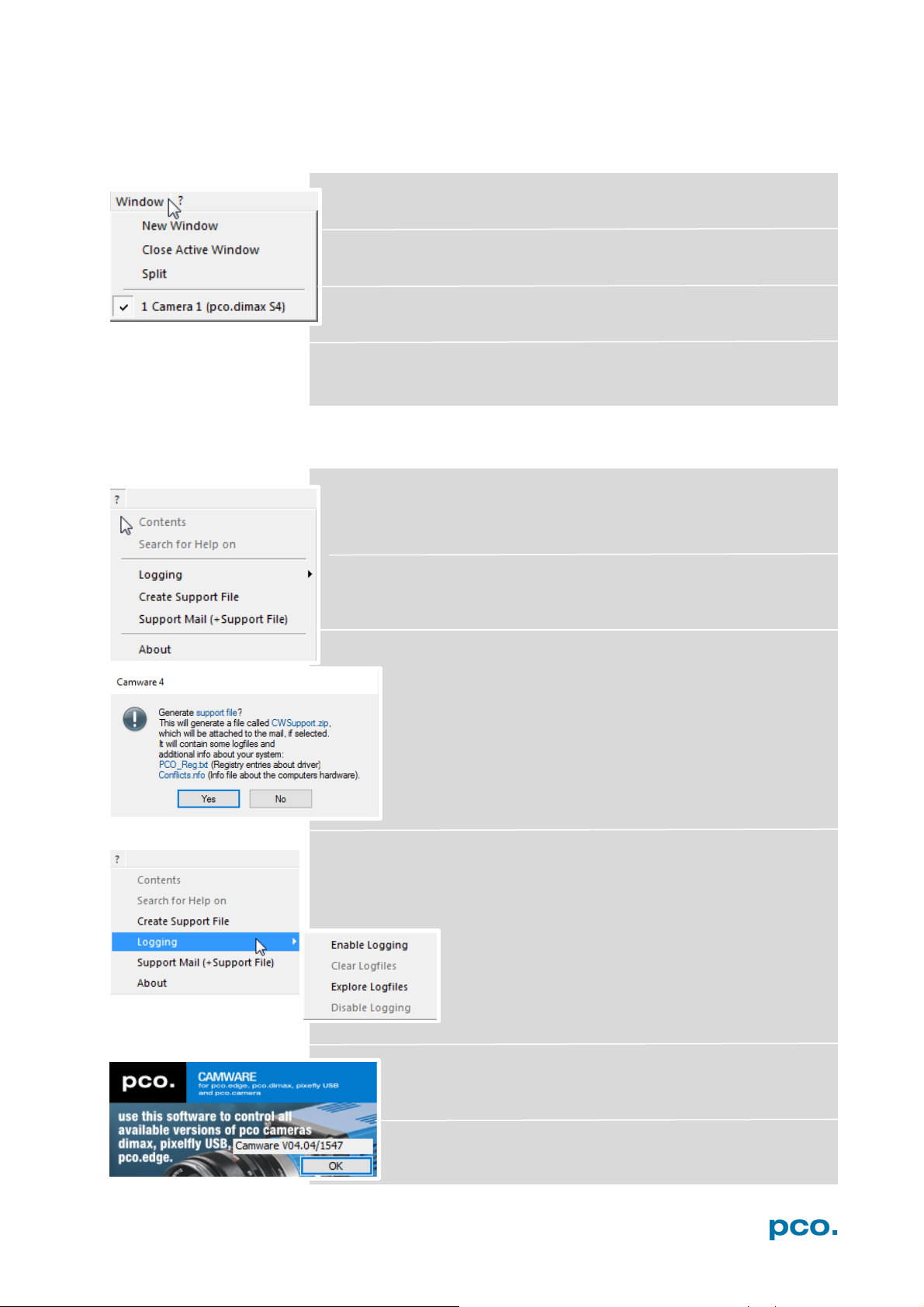
New Window
A new view window will opens.
Close Window
Active window closes.
Split
The view window splits in four quarters.
Camera overview
Shows all connected cameras, e.g. 1 Camera 1 (pco.dimax S4) .
6.9.7 HELP MENU
Contents
Opens the main page of the program help.
Search for Help on
Opens an index list for help.
Create Support File
Press YES to activate log files and reboot Camware and
your pco.dimax.
After log files are activated it is possible to create a support
file. Send this file to the PCO support (see A7)
Logging
Enable Logging:
Activates Camware log files (this cuts down performance)
Clear Logfiles: (only visible if logging is enabled)
This command erases all actual log files
Explore Logfiles:
Opens windows explorer
Disable Logging (only visible if logging is
enabled)
Disables logging
Support Mail
Opens your email-program and the created support file is
added automatically as attachment.
About Camware
Shows program information.
47
Page 48
1
2
1
2
6.9.8 VIEW WINDOW MENU
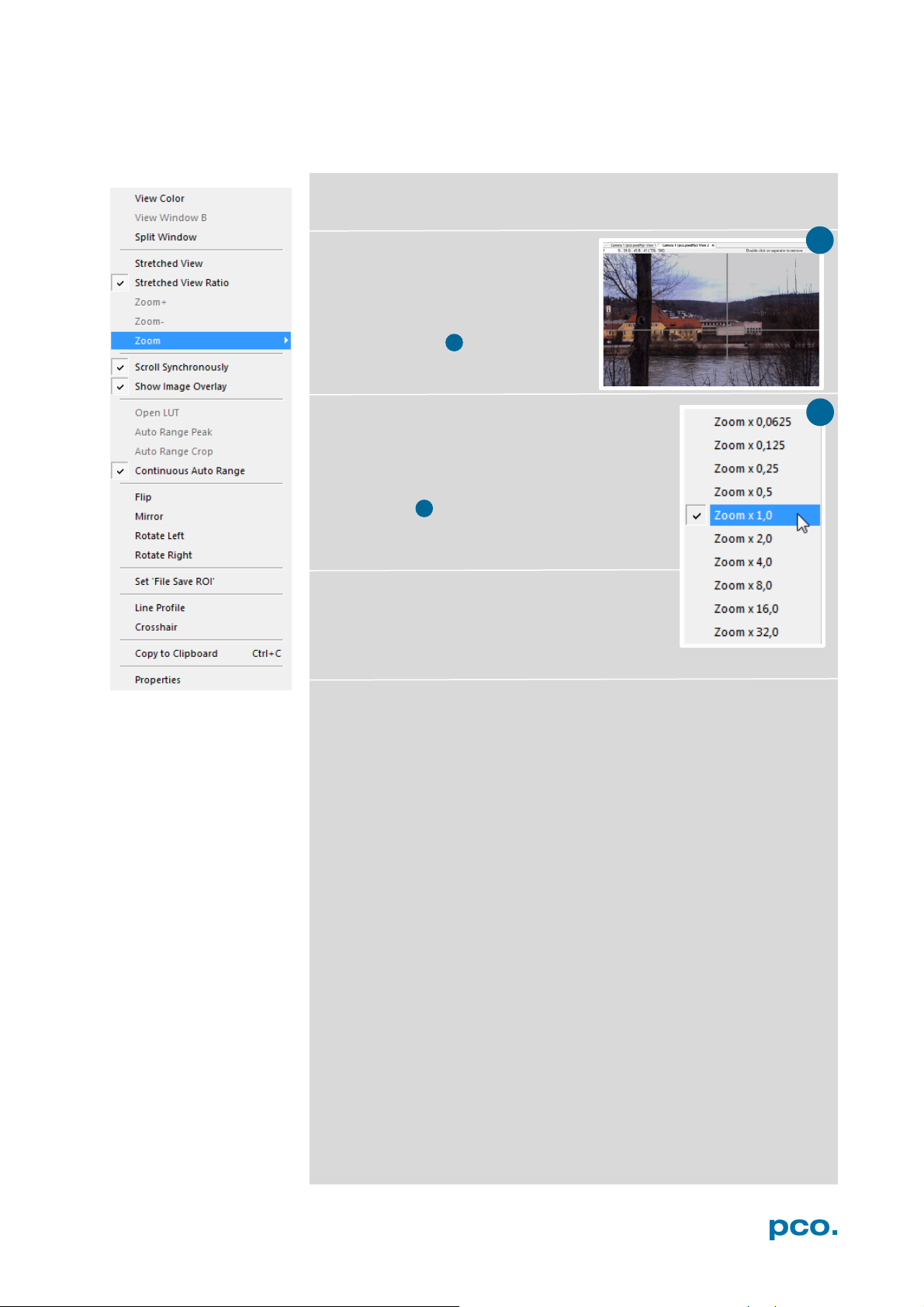
All functions of the View window menu are explained briefly.
Right-click in the View window to open this menu.
View Color: color window.
View Window B: Double Shutter
activation switches to window B
(second image).
Split window: splits the View
window in four parts. Double click
on separator to undo.
Stretched View: image is fitted into the display
window.
Stretched View Ratio: aspect ratio is
maintained.
Zoom +/-: image zoom (only available if
Stretched View is deactivated).
Zoom: set the Zoom factor (from 0.0625 to 32).
Scroll Synchronously: scroll synchronously
through all open image windows (only available
if Stretched View is deactivated).
Show Image Overlay: activates the overlay see 6.4
Open LUT: opens look-up table file for false-color representation.
Auto Range Peak: searches for the minimum and maximum 14 bit
intensity values of the image. Given these numbers the converter
scales the 8 bit display (256) within these two values.
Auto Range Crop: sets the converter to ignore the extreme intensity
values of the image and scales the display in a smaller range. Thus
dark or bright light spots, reflections, etc. are cut off.
Continuous Auto Range: (Crop): enables the automatic min/max
function (Auto Range Crop) during record and replay.
48
Page 49
6 CAMWARE 4 SOFTWARE
Flip/Mirror: image will be flipped or mirrored.
Rotate Left/Right: rotates the image in steps of 90°.
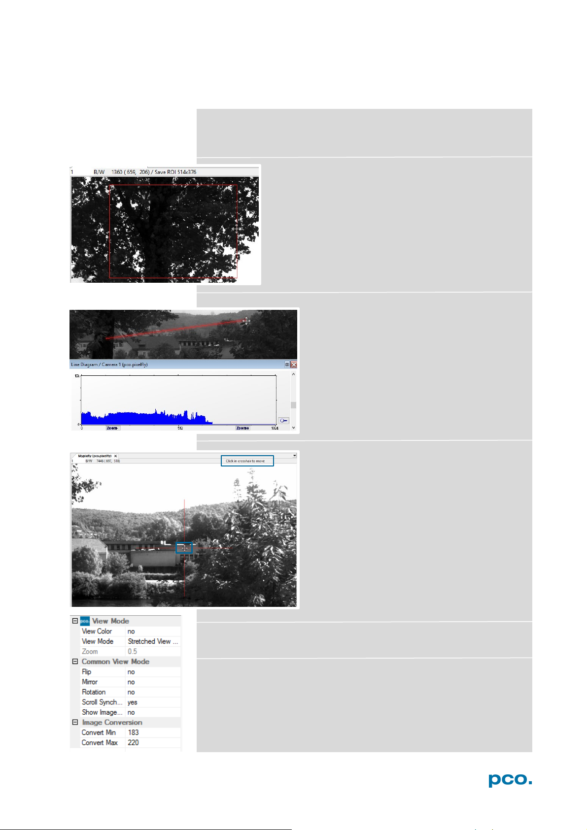
Set ‘File Save ROI’: if you want to save just a part of
the recorded image (region of interest), it is possible to
draw a rectangle with the mouse. This rectangle is valid
for all recorded images and can be dragged at its
edges.
Line Tool: point the mouse where the line
should start and left-click. Move the mouse to
the desired line end and left click again. The
line may be stretched, shrunk or moved by
grasping its end point. A Line Diagram opens.
The graph in the length of the line (units: pixel)
is displayed showing the intensity values of the
pixels along the red line.
Crosshair: activates a centered crosshair. Size
and color are selectable see chapter 6.9.2 →
Options.
To move the crosshair drag it by mouse. Reset
it to center position by double-click into the
center of the crosshair.
Copy to Clipboard: will copy the actual image to clipboard.
Properties: shows the current settings for View Mode / Common
View Mode and Image Conversion.
49
Page 50
1
2
2
1
6.9.9 ADDITIONAL FEATURES
White Balance by Mouse
Change white balance by mouse: Press the CTRL (STRG) and shift
button simultaneously and select a white or gray area within the
image by dragging a rectangle while holding the left mouse button.
The pixel values within the coordinates of the selection rectangle are
used for calculating a new white balance.
For best results we recommend to use the white balance button in
the Convert Control Color (see 6.3.8).
Setting Contrast Area by Mouse
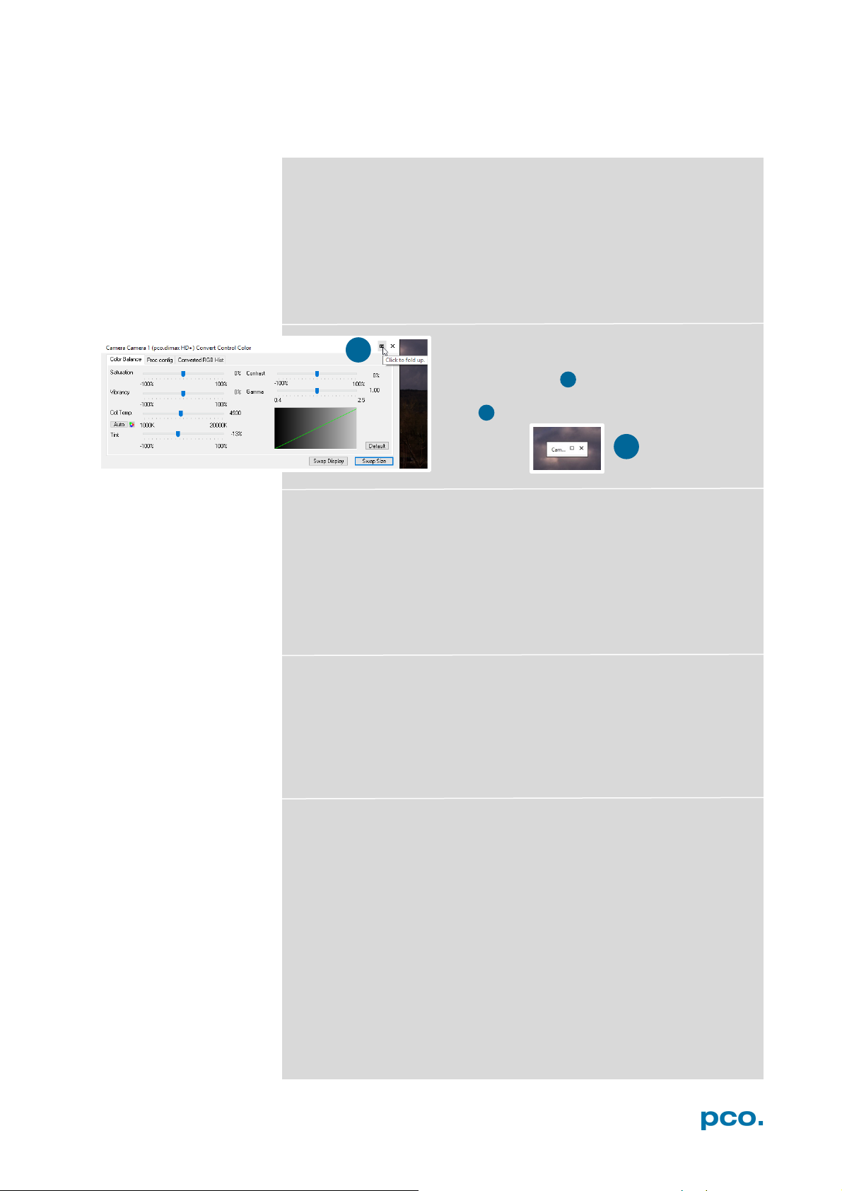
Fold Up Window
The Convert Control windows can be
minimized / folded. Move the pointer over the
bar and the window will unfold
again .
Control the minimum and maximum values used for the conversion
from 16 bit to 8 bit with the mouse. Move the mouse cursor into a
region which should be shown with maximum contrast. Press the
shift and the left mouse button. Hold down the mouse button while
changing the selection rectangle's size by moving the mouse. After
releasing the mouse button the coordinates of selection rectangle act
as a border for calculating the minimum and maximum values.
Setting a new ROI by Mouse
Change Region of Interest by mouse (see ROI 6.3.2.). Just press the
CTRL (STRG) button and drag an area with the left mouse button.
The coordinates of the selection rectangle are used for calculating a
new region of interest, which will be adapted to the camera
capabilities automatically. Reset the ROI to maximum by pressing the
CTRL (STRG) button and the right mouse button.
Short Cut List
• Start / Stop record: ENTER
• Acquire Picture: SPACE (Soft Trigger mode)
• Acquire Sequence: STRG + A / CTRL + A
• Auto Save: ALT + D
• Export File: STRG + T / CTRL + T
• Export Recorder Sequence: STRG + O / CTRL + O
• Open Raw Image File: STRG + I / CTRL + I
• Open Raw Recorder Sequence: STRG + R / CTRL + R
• Save Raw Image File: STRG + E / CTRL + E
• Save Raw Recorder Sequence: STRG + S / CTRL + S
50
Page 51

APPENDIX
A1 TECHNICAL DATA 52
DATA SHEET 52 A1.1
REVERSE WITH CAPTION 53
DIMENSIONS 54
INPUT WINDOW FILTER 56
MOUNTING 56
A2 GIGABIT ETHERNET INTERFACE 57
QUICK INSTALLATION GUIDE 57 A2.1
NETWORK INTERFACE CARD 58
A2.2.1 IP ADDRESS CONFIGURATION 59
A2.2.2 JUMBO PACKETS / BUFFER SETTINGS 60
A2.2.3 RECOMMENDED HARDWARE 61
A2.2.4 NETWORK ENVIRONMENT/PATCH CABLE 61
A2.2.5 CABLE LENGTH 61
SINGLE/MULTIPLE CAMERA OPERATION 62 A2.3
A2.3.1 SINGLE CAMERA 62
A2.3.2 MULTIPLE CAMERAS 63
A2.3.2.1 SWITCH 63
A2.3.2.2 SEVERAL NICS 64
DRIVER INSTALLATION 65 A2.4
A2.4.1 UNINSTALL DRIVER 65
A2.4.2 DE/ACTIVATING FILTER DRIVER (WIN7/8) 65
CALIBRATION TOOL 66 A2.5
A2.5.1 FIRMWARE WARNING 67
A2.5.2 NO ACCESS 67
A2.5.3 NETWORK AND PACKET DELAY 68
A2.5.4 SET CAMERA IP ADDRESS & PACKET DELAY 69
A2.5.5 IMAGE TRANSFER DATA RATE 70
A2.5.6 CAMERA TEST 70
A2.5.7 RESET IP ADDRESS 71
A2.5.8 TOOL TIPS 72
HELP GUIDE 72 A2.6
PERFORMANCE 73
A3 ACCESSORIES 74
BREAKOUT CABLE 74 A3.1
EXTENSION BOX 74
LENS CAGE 76
A4 MOUNT ADAPTER 77
PCO F-MOUNT ADAPTER 77 A4.1
CHANGE F- TO C-MOUNT / FOCAL DISTANCE 78
A5 IMAGE FILE FORMATS 80
A6 CUSTOMER SERVICE 82
SERVICE 82 A6.1
MAINTENANCE 82
RECYCLING 82
LOGFILE / SUPPORT FILE 83
TROUBLE SHOOTING 84
A7 INDEX 85
ABOUT PCO 86
A1.2
A1.3
A1.4
A1.5
A2.2
A2.7
A3.2
A3.3
A4.2
A6.2
A6.3
A6.4
A6.5
51
Page 52
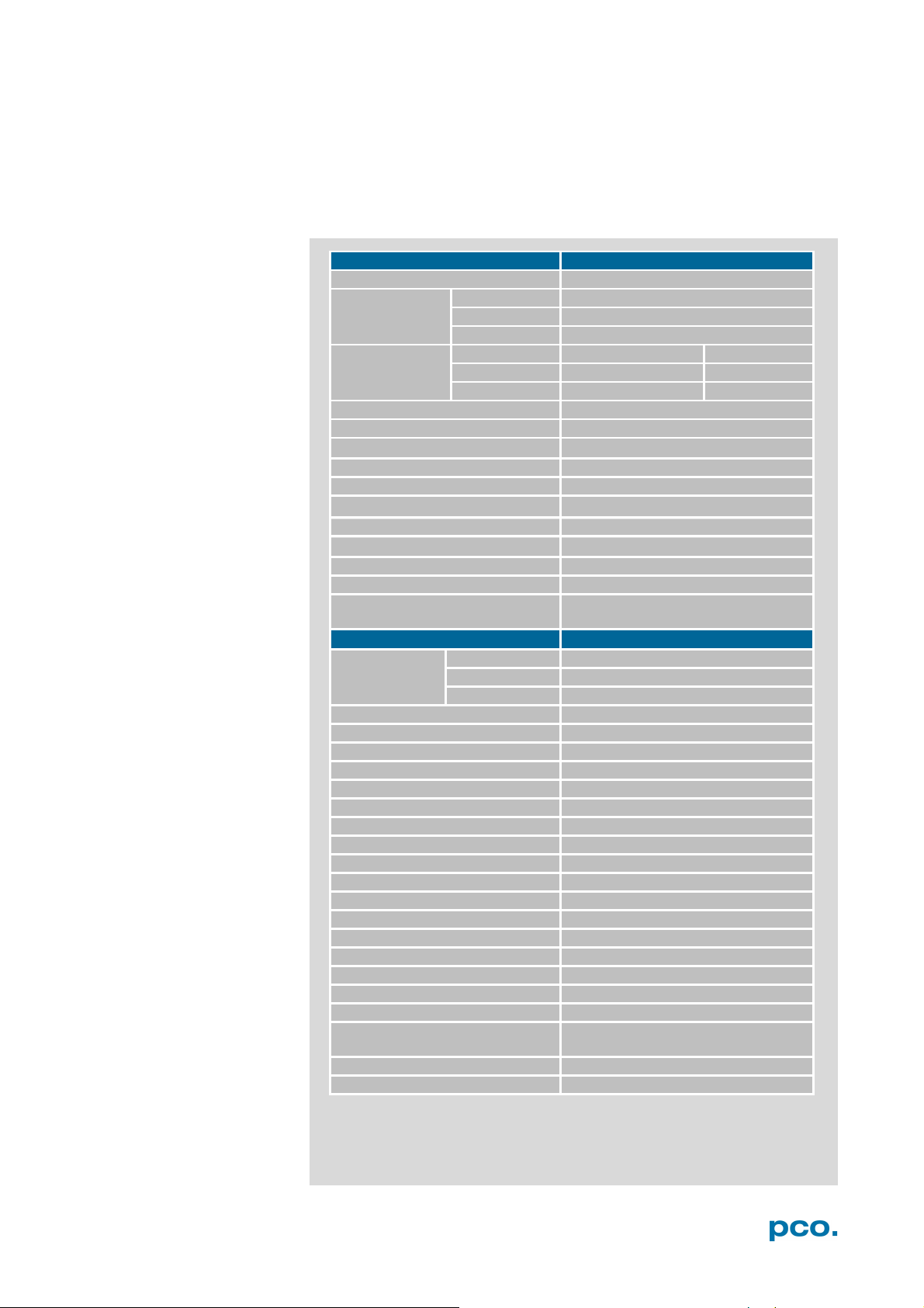
Sensor
Image sensor
Proprietary sensor
cs1
1296 x 1024 pixels
cs3
1920 x 1440 pixels
cs4
2016 x 2016 pixels
cs1
14.26 x 11.26 mm²
18.17 mm
cs3
21.12 x 15.84 mm²
26.40 mm
cs4
22.18 x 22.18 mm²
31.36 mm
Pixel size
11 x 11 μm²
Shutter mode
Global Shutter
Fullwell capacity
36 000 e-
Quantum efficiency
50% @ peak
Spectral range (b/ w sensor)
290 … 1100 nm
Readout noise
22 e- (typ.) 18 e- (CDI)*
Dynamic range
1600:1, 64 dB ; 2000:1, 66 dB (CDI)*
Dark current
530 e-/pixel/s @ 20°C
Non-linearity
< 0.5% (diff.), < 0.2% (integr.)
DSNU (dark signal non-uniformity)
< 0.6 counts rms @ 90% center zone
PRNU (photo response nonuniformity)
< 1% @ 80% signal
Camera
cs1
3086 fps
cs3
1603 fps
cs4
1102 fps
Exposure time
1.5 μs … 40 ms
Dynamic range A/D
12 bit
Region of interest
24 x 4 pixel steps (centered)
Internal memory
9 GB
Output signals
Status exposure/Status busy
Multi-camera Synchronization
Sync In/Out (Master/Slave), PLL
Trigger / Synchronization signals
TTL, RS-485, Contact
Data interface
Gigabit Ethernet
Time stamp
in image (1 μs resolution)
Time code input
IRIG-B unmodulated (optional)
Interframing time
3.58 μs (optional)
Operating temperature
0° - 40°C
Housing
enclosed housing
Shock resistance
150g for 11ms
Power supply range
15 - 48 V DC
Power consumption
27 W
Camera connector
LEMO (18-pins: 2B-318-CLN)
Lens mount
C-mount + F-mount /
EF-mount (optional)
Mounting threads
2x ¼”, 2x M4, 14x M6
Weight
0.985 kg (C-mount version)
A1 TECHNICAL DATA
DATA SHEET A1.1
Resolution
Sensor format /
diagonal
Max. fps @full
resolution
*in correla ted double image mode (CDI) the readout noise is reduced and therefore the
intra-scene dynamic is improved.
52
Page 53
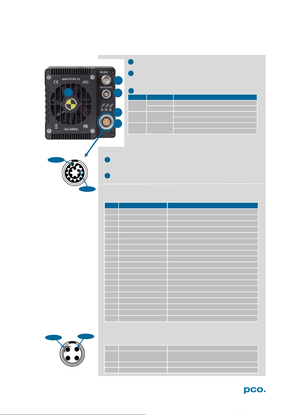
A1 TECHNICAL DATA
Pin 1
Pin18
1
2
3 4 5
LED
Color
Description
PWR
Green
Voltage applied
Red
Error state
LAN
Orange
Network connection is active (flashing)
If connection is lost: permanent light
REC
Blue
rec state = on: permanent light:
Flashes while rec after T0
Pin Signal name
Color
1
Ethernet A-
Orange
2
Ethernet D-
Brown
3
Ethernet B-
Green
4
Ethernet B+
White (Green)
5
Ethernet C+
Black
6
Status +
Red
7
+SUPPLY
Orange (Bl 1)
8
+SUPPLY
Red (Bl 2)
9
SYNC+
Yellow
10
SYNC-
Green
11
-SUPPLY
Gray (Bl 3)
12
-SUPPLY
Black (Bl 4)
13
Ethernet A+
White (or)
14
Ethernet D+
White (br)
15
Ethernet C-
White (bl)
16
Status- /CamPresent
Blue
17
TRG+
White
18
TRG-
Brown (for TTL: not connected with GND)
Case
Ethernet Screen TRG shield SYNC shield
1
SUPPLY OUT
12V Out Standard (15 W)
2
SUPPLY IN & RXD
(RXD bidirectional modulated)
Communication battery and lens controller
3
TXD
Communication battery and lens controller
4
GROUND
1
2 3 4
5
Pin 1
Pin 4
REAR PANEL A1.2
HD-SDI BNC plug for 75 Ω coaxial BNC cable, see A5
LEMO II power connector for Battery, electronic Lens
controller or HD-SDI monitor
Status LEDs
4 LEMO I Connector for Synchronization, Power Supply, Trigger
Signals and GigE network connection
5 Fan
Lemo I Pin assignment (EEG.2B.318.CLN)
(Fitting male connector: FGG.2B.318.CYCD92ZN)
Lemo II Pin assignment (EEG.0B.304.CLN)
(Fitting male connector: FGG.0B.304.CYCD52Z)
53
Page 54
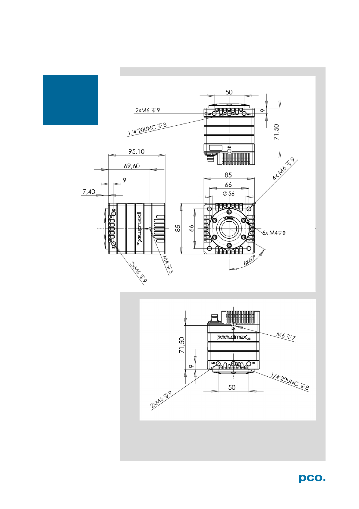
NOTE
DIMENSIONS A1.3
F-Mount back
focal length:
46.50 mm.
C-Mount: 17.526
mm
All dimensions given in millimeter.
54
Page 55
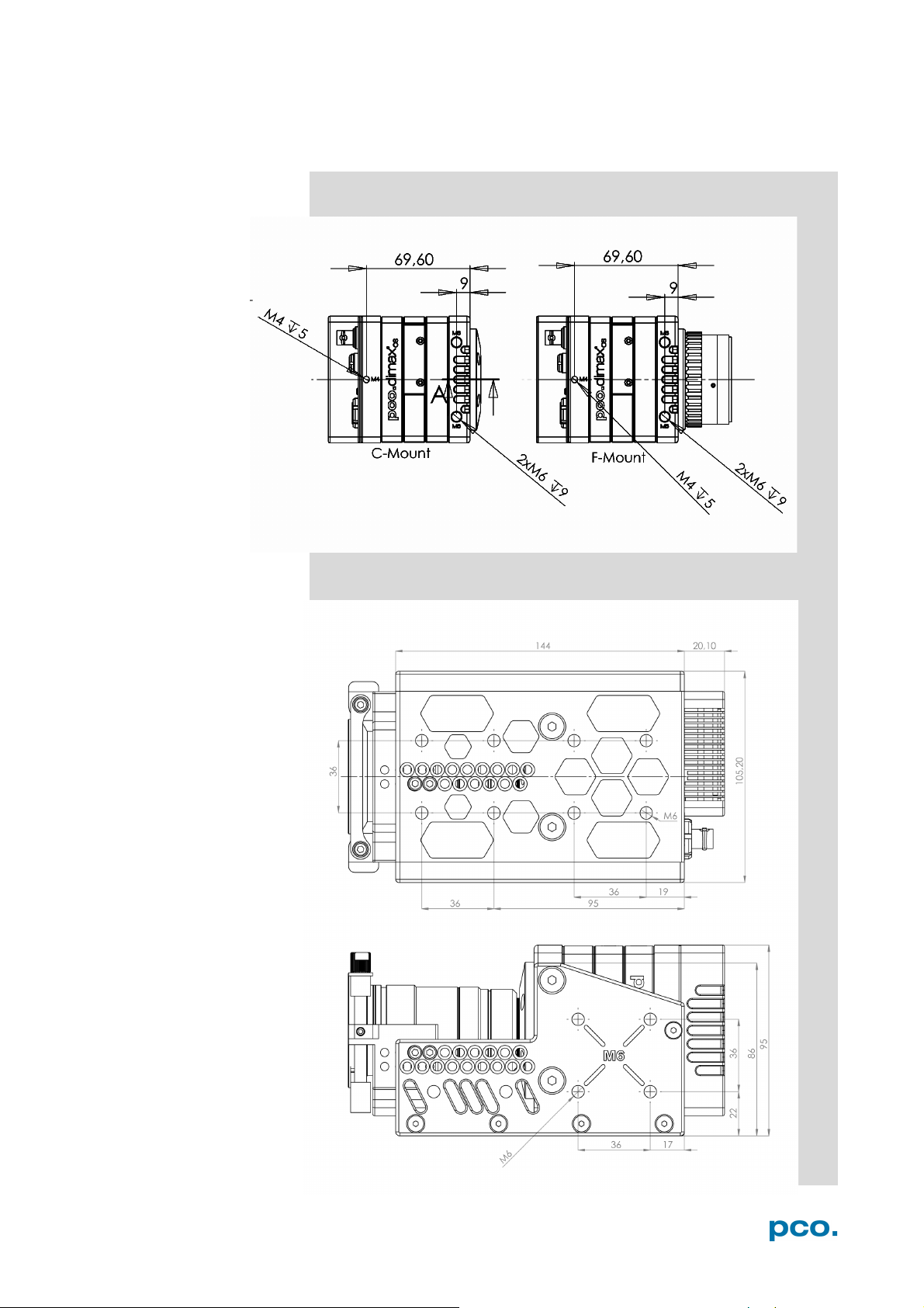
A1 TECHNICAL DATA
C-Mount vs F-Mount
Lens cage
55
Page 56
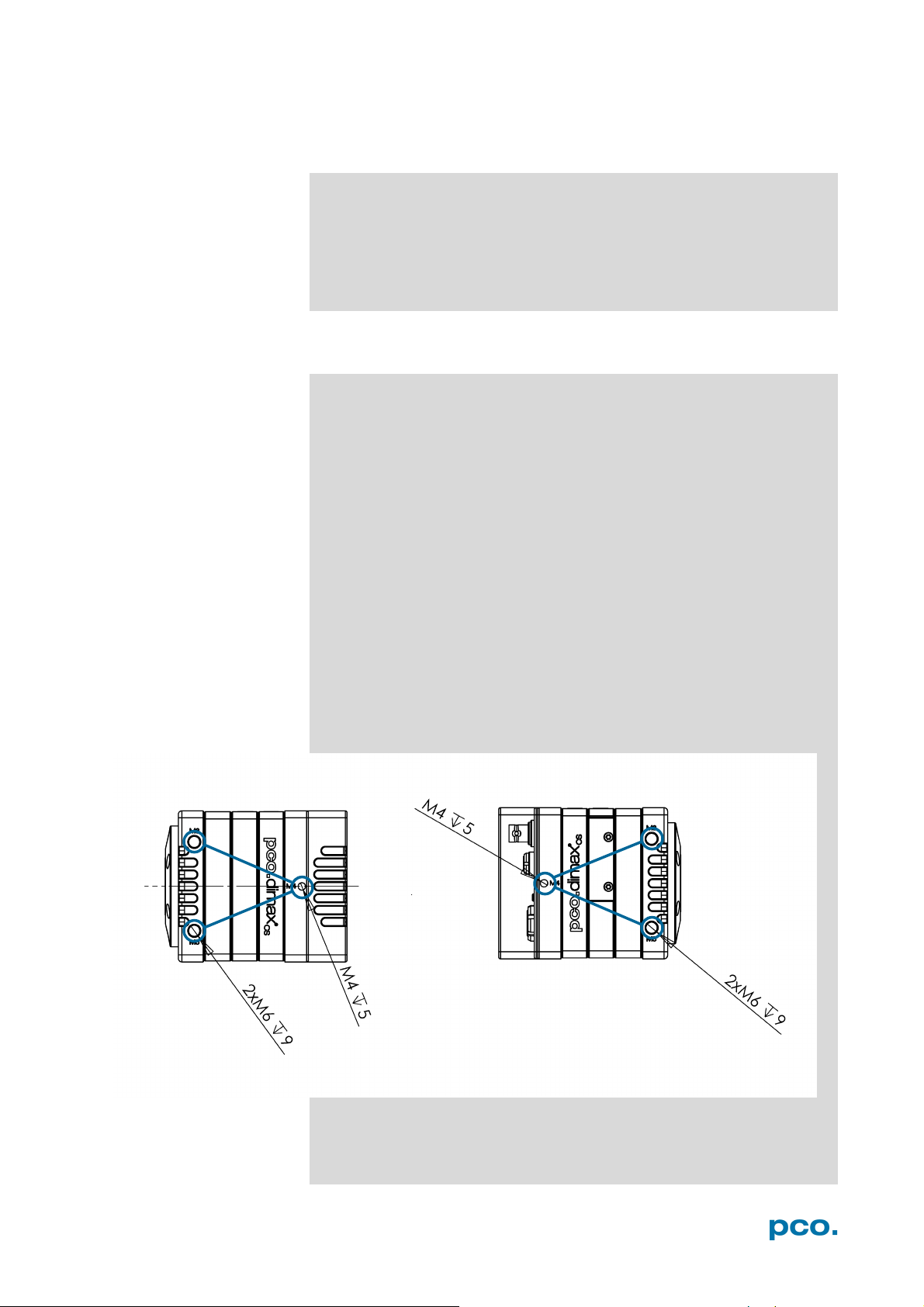
INPUT WINDOW FILTER A1.4
The safety glass as input window in front of the color sensor acts as
anti-reflective coated filter (98% light transmission).
Monochrome cameras have a Suprasil input window.
The spectral range of t he pco.dimax color is: 400 nm – 700 nm.
MOUNTING A1.5
A stable mounting of the camera system is required for applications
with accleration forces of up to 150G.
• PCO recommends to use the mounting threads of the
pco.dimax cs camera.
• It is recommended to primarily use the threads on the black
front part of the camera
• It is not allowed to only use the M4 threads near the rear side
of the camera
• Always mount the camera by a three-point screw
connection.
• Always use two sides of the camera for the screwing
• Carefully tighten the screws
The body of the camera is made of aluminium and the threads are
reinforced with HeliCoil
Drawings show the M6 and M4 threads on the left and right side of
pco.dimax cs.
®
inserts.
56
Page 57
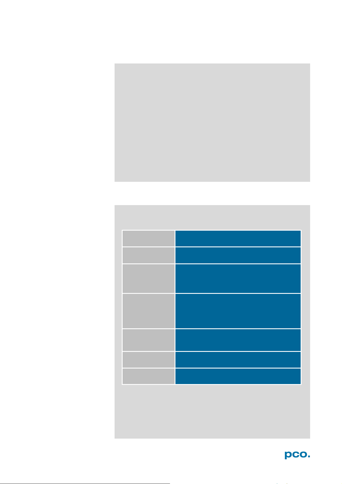
A2 GIGABIT ETHERNET INTERFACE
First Step
Install network interface card (NIC)
See chapter A2.2
Second Step
Configure the IP address of your NIC
See chapter A2.2.1
Install GigE driver
Deactivate (uncheck) the GigE driver
See chapter A2.4.2
Apply PCO GigE Calibration Tool
Sixth Step
Test your calibration
After successful calibration
Start Camware
A2 GIGABIT ETHERNET INTERFACE
GigE is an interface standard for high-performance industrial cameras
developed by a group of about 50 companies. GigE is based on the
Gigabit Ethernet standard which uses standard Ethernet category
cabling. The standard is trying to unify protocols currently used in
machine vision industrial cameras and let 3rd party organizations
develop compatible software and hardware
(www.machinevisiononline.org).
System requirements (check PCO website for latest versions)
• GigE PCO firmware > V2.00
• Camware software package
• GigE driver generation 2 > V4.0.0.00
• Complete network environment must be GigE compliant
Cat5e or higher patch cable
QUICK INSTALLATION GUIDE A2.1
Follow the steps in this sequence. Additional information can be
found in the respective subchapters.
NIC
IP Address
Third Step
Driver
Follow instructions.
See chapter A2.4
Driver 4.2
Fourth Step
Uncheck
Fifth Step
Calib Tool
Test
Final Step
at each NIC that will not physically be connected to
pco.camera with GigE
your camera (Win 7/8)
for camera calibration
See chapter A2.5
see chapter A2.5.6
57
Page 58
NETWORK INTERFACE CARD A2.2
Your computer must have a network interface card (NIC) to connect
the camera via GigE, either an onboard NIC (mainboard) or a plug-in
card.
PCIe
Ideally it is a PCI Express NIC to achieve the highest data transfer
rates.
The PCI Express interface allows a faster and more stable data
transfer rates than ordinary PCI interfaces. Finally, NIC’s performance
depends on the used chipset. Recommended are chipsets from Intel.
Driver
Make sure the specific driver of the NIC is installed to your
Operating System (OS) – Otherwise the OS may use a standard plug
& play driver not top-performing with the hardware.
Configuration
For checking your network connection or changing parameters open
the properties dialog of your LAN connection. See chapter A2.2.1.
Mainboard Slot for NIC
Installing a NIC in a PCIe slot of your computer, check the data
transfer rates of the preferred slot. Some mainboards do not provide
the required data transfer rates on all PCIe slots. See A2.6.
58
Page 59
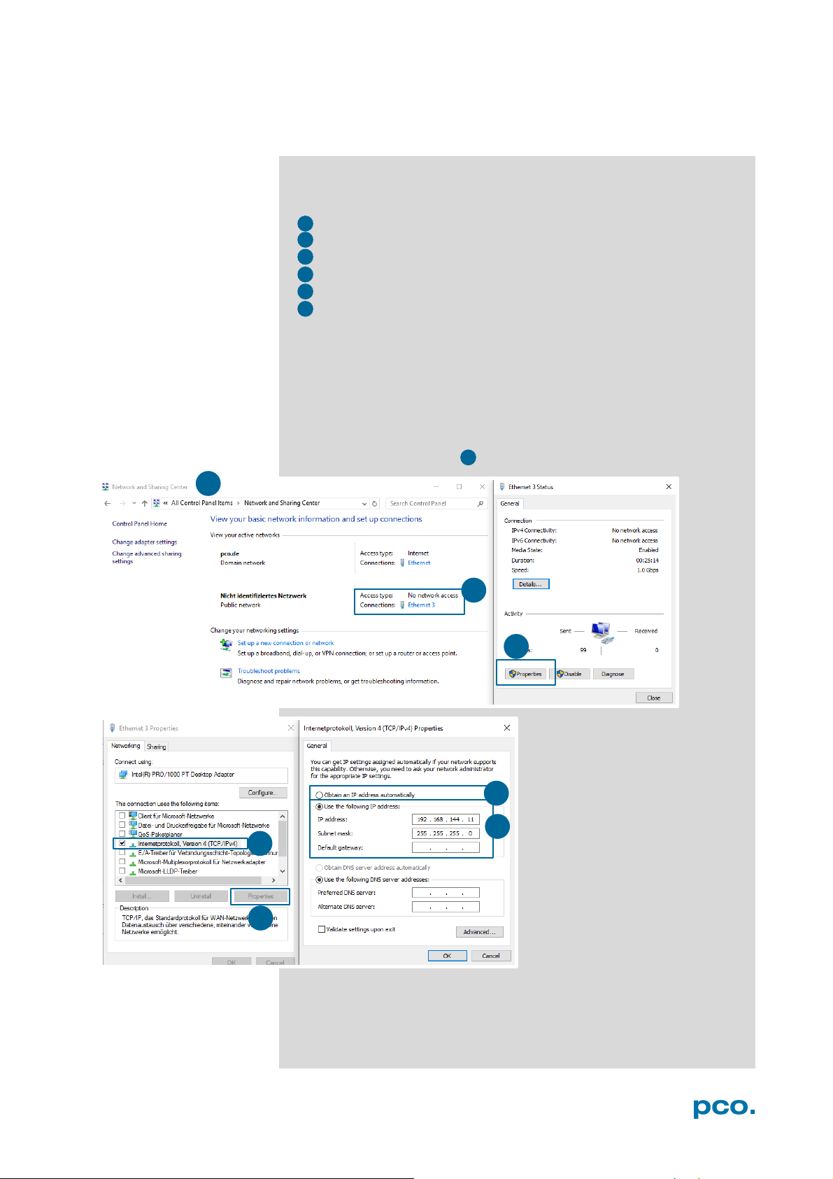
A2 GIGABIT ETHERNET INTERFACE
1
2 3 4 5 6
1 2 3
4
5 6 7
7
A2.2.1 IP ADDRESS CONFIGURATION
How to configure an IP address manually: exemplary for
Windows 10 (configuration for Win 7/8 is identical)
• Start → Control Panel → Network and Sharing Center
• Select your GigE network connection
• Properties
• Internet protocol version 4 (TCP/IPv4)
• Properties
• Use the following IP address
Use internet protocol version 4 (TCP/IPv4) only, TCP/IPv6 is not
supported by PCO cameras.
Recommended: configure your IP address manually.
The use of Dynamic Host Configuration Protocol (DHCP) is not
recommended. DHCP is active if obtain an IP address
automatically is selected .
59
Page 60
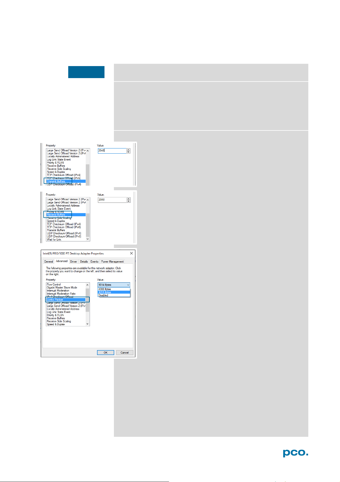
NOTICE
A2.2.2 JUMBO PACKETS / BUFFER SETTINGS
These settings are for experts’ use only!
To change these settings:
Win7/8/10: Start → control panel → network and sharing center →
change adapter settings → select network connection e.g. Ethernet 2
connected to your camera → right-click→ properties → configure →
advanced
Jumbo Packets and Transmit / Receive Buffer are settings
of your network card and can be changed with the windows
control panel.
These buffer settings help to reduce the loss of data
packets (images) while transferring data from camera to
network interface card.
Transmit / receive buffer (recommended for GbE network
only)
For some NIC’s you may set parameters manually which
affect the stability of the data transfer. The most important
ones are Transmit and Receive Buffer.
Always set the value of these parameters to their maximum.
Jumbo packet (expert use only –use with one camera
only)
Activate Jumbo Packet(s) to reduce overheads and CPU
cycles, in case your network adapter supports it.
All network components must be Jumbo Packet compatible.
You must use Calib Tool to set Packet Size of your camera,
see A2.5.
60
Page 61
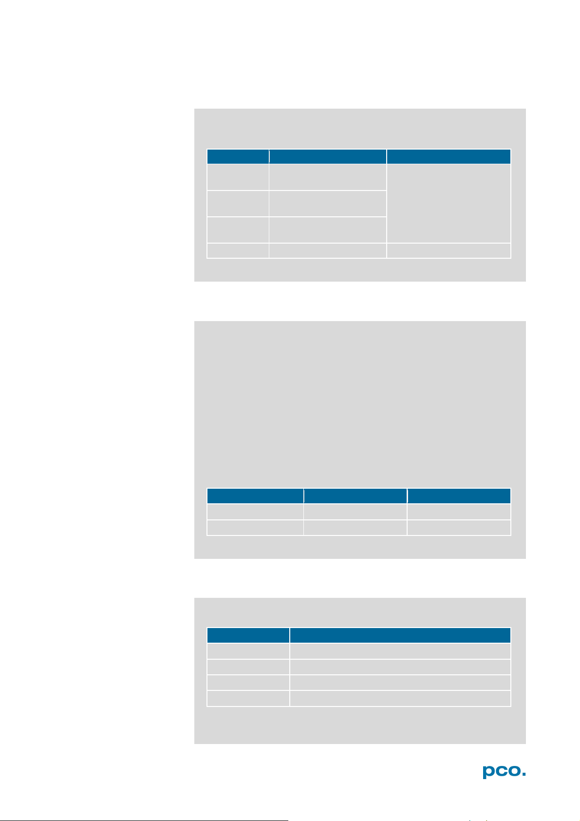
A2 GIGABIT ETHERNET INTERFACE
Hardware
GbE
10GbE
NIC
Intel Ethernet Server
Adapter I210 T1
Intel Ethernet Converged
NIC
Intel Ethernet Server
Adapter I350 T2 (2 port)
NIC
Intel Ethernet Server
Adapter I350 T4 (4 port)
Switch
Standard 1 Gbit switch
Netgear ProSAFE XS716T
GbE
10GbE
Network cable
Cat 5e, 6, 7
TP Cat 7e
Max. cable length
100m
100m
length
standard
10 m Cat 6 (for Extension Box)
optional
0.5 m; 2 m; 5 m; 12.5 m; 30 m; 50 m
maximum
100 m
included
breakout cable (3m Cat 6 RJ-45)
A2.2.3 RECOMMENDED HARDWARE
The following hardware components have been tested by PCO. Their
use guarantees stable data transfer rates.
Network Adapter X550-T2
A2.2.4 NETWORK ENVIRONMENT/PATCH CABLE
A correct network configuration is crucial to achieve the best image
data transfer rates. It is mandatory that any component used for the
network connection between camera and computer is compatible
with a data transfer rate of 1000 MBit/s for Gigabit Ethernet or 10
Gigabit/s for 10 Gigabit Ethernet.
Some of these components are the NIC, router, hub, switch, etc., but
also the patch cable.
The quality of patch cables is specified in categories. It is necessary
to use category 5e-, 6-, or 7- patch cables for a network connection
with a data transfer rate of GbE, for 10GbE network only Twisted
Pair Cat 7e.
A2.2.5 CABLE LENGTH
Available cable lengths:
61
Page 62
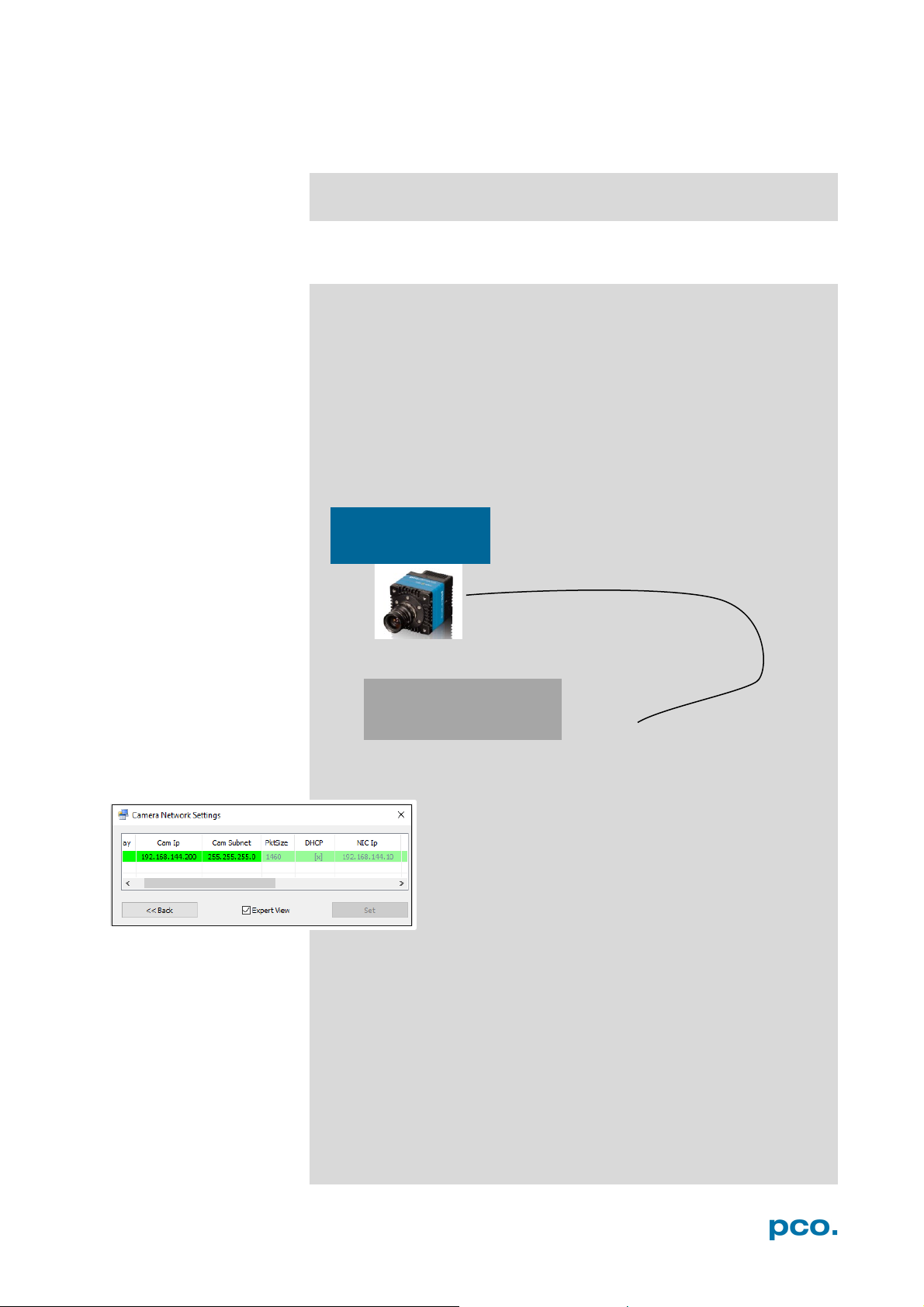
Camera
Network interface card
SINGLE/MULTIPLE CAMERA OPERATION A2.3
The subchapters explain single and multi-camera use.
A2.3.1 SINGLE CAMERA
Single camera operation means camera and computer are
connected via Point to Point connection, i.e. direct connection via
LAN cable between the GigE connector of the camera and the
network interface card of your computer.
• Connect NIC and camera via patch cable directly.
• Configure the IP address and Subnet mask of your NIC, see
A2.2.1
Configuration example:
IP: 192.168.144.200
Sub mask: 255.255.255.0
IP: 192.168.144.10
Subnet mask: 255.255.255.0
Calibration Tool:
Use the Calibration Tool to configure these settings,
see chapter A2.5 (e.g. configuration of a pco.dimax
camera connected to a NIC).
62
Page 63
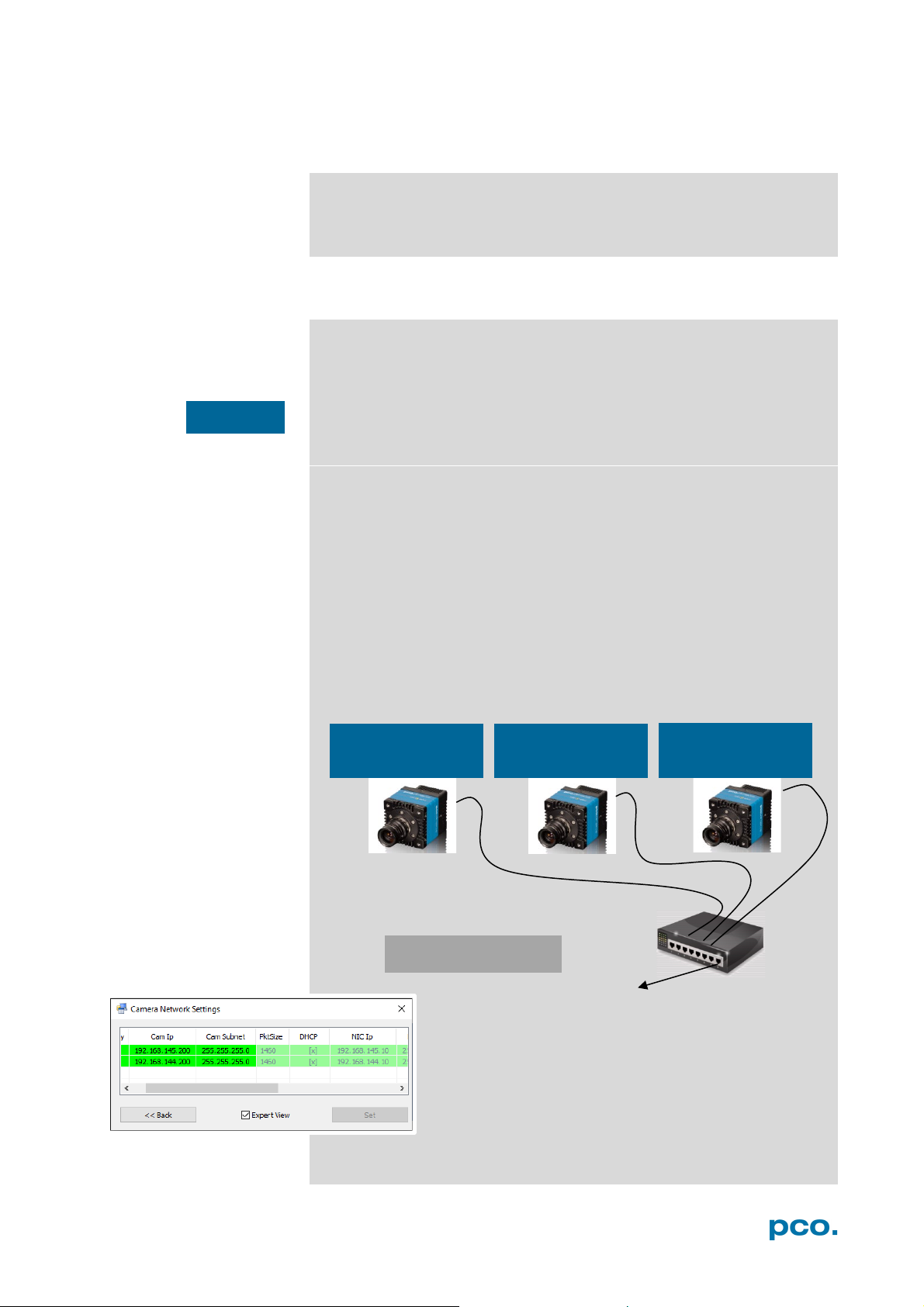
A2 GIGABIT ETHERNET INTERFACE
NIC IP: 192.168.144.10
Sub. mask: 255.255.255.0
Camera 1
Sub. mask: 255.255.255.0
Camera 2
Sub. mask: 255.255.255.0
Camera 3
NOTICE
A2.3.2 MULTIPLE CAMERAS
There are two basic ways to connect multiple cameras to a
computer: with a switch or with one network interface port per
camera.
A2.3.2.1 SWITCH
The network settings using a switch can be configured manually or
with a DHCP server.
Using a switch may cause network performance problem: if the
connected cameras require a higher bandwidth than provided by the
switch and the associated network card. See also Network and
Packet Delay A2.5.3
Via switch without a DHCP server:
• Camera and NIC IP addresses have to be set manually.
• The subnet of camera and NIC, i.e. the first three sections of
camera and NIC TP address must be identical (see configuration
example).
• The next section of each camera and NIC IP can be any value
between 1 and 254, but may not be the same for both devices.
• For example: NIC IP 192.168.144.10; a proper camera IP would be
192.168.144.100. The Subnet mask must be exactly the same, e.g
255.255.255.0.
Configuration example:
IP: 192.168.144.200
IP: 192.168.144.201
IP: 192.168.144.202
Sub. mask: 255.255.255.0
Calibration Tool:
Use the Calibration Tool to configure these settings,
see chapter A2.5 (e.g. configuration of a switch with
two pco.dimax cameras).
63
Page 64
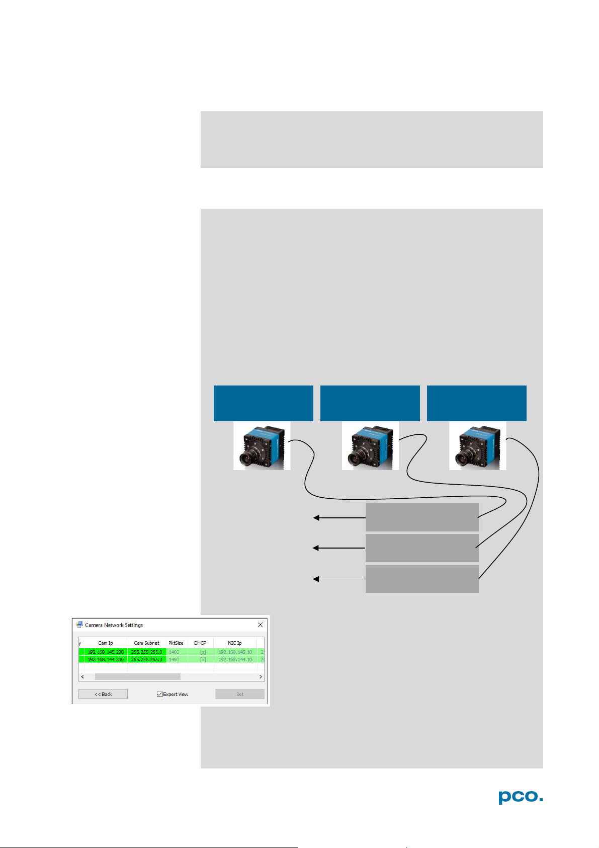
NIC1 IP: 192.168.144.10
NIC2 IP: 192.168.145.10
NIC3 IP: 192.168.146.10
Camera 1
Camera 2
Camera 3
Via switch with DHCP server:
• NIC and cameras obtain the IP addresses automatically by a
A2.3.2.2 SEVERAL NICS
Via several NIC’s (or NIC ports) at one computer:
• Camera and NIC IP addresses have to be set manually.
• Each camera and NIC pair needs its own subnet (see
configuration example).
• Using NICs with multiple ports: check the bandwidth of the PCIe
slot.
The following example shows how to calibrate IP addresses when
connecting cameras to individual NIC’s. Most important is that each
camera & NIC combination needs its own subnet and the camera
IP address and subnet and NIC IP address and subnet have to
match.
Configuration example:
IP: 192.1 68 .144.200
Sub. mask: 255.255.255.0
DHCP server.
IP: 192.1 68 .145.200
Sub. mask: 255.255.255.0
IP: 192.1 68 .146.200
Sub. mask: 255.255.255.0
Calibration Tool:
Use the Calibration Tool to configure these settings,
see A2.5 (e.g. configuration of two NIC’s with two
pco.dimax cameras).
64
Sub. mask: 255.255.255.0
Sub. mask: 255.255.255.0
Sub. mask: 255.255.255.0
Page 65
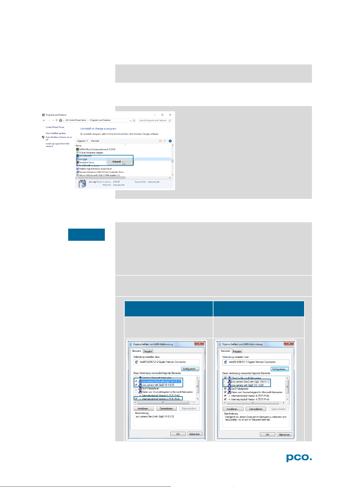
A2 GIGABIT ETHERNET INTERFACE
Camera is operated with this
Camera is NOT operated with this
network card.
Activate both GigE drivers and
Deactivate both GigE drivers.
NOTICE
DRIVER INSTALLATION A2.4
GigE driver installation see chapter 4.2
A2.4.1 UNINSTALL DRIVER
Open the file GigE_Uninstall.exe
(Win7/8: Right-click and select Run as
Administrator)
Win 7/8/10
Click Start → Control Panel → Programs and
Features → Select: pco gige and double-click
to uninstall
Or on Win7/8: Start → Programs → Digital
Camera Toolbox → pco.gige/pco.gige2 →
Uninstall
A2.4.2 DE/ACTIVATING FILTER DRIVER (WIN7/8)
It is mandatory that the PCO GigE driver is only activated at the
specific NIC physically connected to your camera. In addition, just
the service pco.camera with GigE and the Internet protocol
Version 4 (TCP/IPv4) should be activated for each NIC used for PCO
cameras.
With active virus scan/firewall an connected camera may not be
recognized.
Tick the pco.camera with GigE check box for activating or
deactivating GigE drivers.
network card.
internet protocol version 4 TCP/IP.
Deactivate all other elements.
Activate all other elements.
65
Page 66
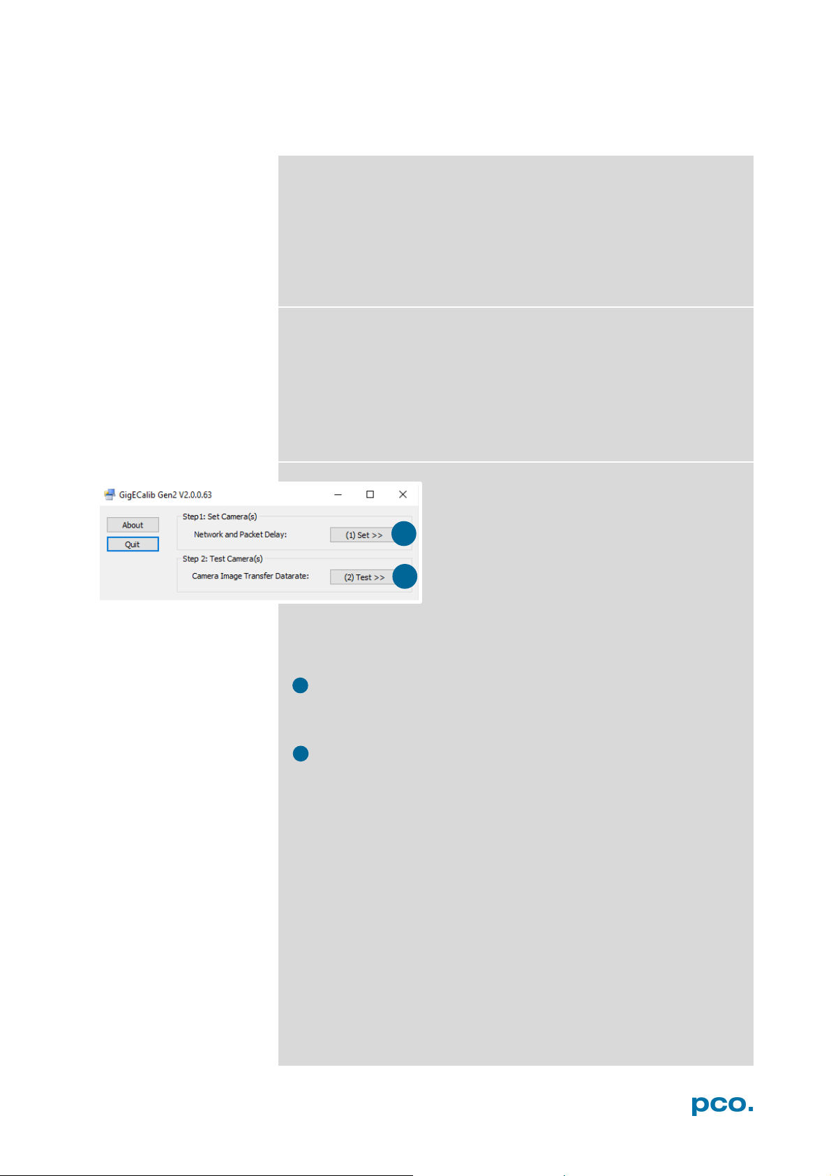
1
2
2
1
CALIBRATION TOOL A2.5
The PCO GigE Calibration Tool is part of the PCO software package,
starts automatically after the PCO GigE Driver installation and is
automatically linked to your desktop.
• Win 7: Start → All programs → Digital Camera Toolbox →
pco.gigeG2 → GigECalib
• Win10: Start → All Apps → Digital Camera Toolbox →
GigECalib
The purpose of this software:
• Set camera network parameter (Packet Delay A2.5.3).
• Change the network settings (IP address & subnet mask
A2.5.4) of the camera.
• Display connected PCO GigE cameras.
• Check the correct network configuration.
• Test the data transfer rate (Test A2.5.5).
How does it work?
The Start Dialog offers two possibilities:
• Choose Set
network parameters like IP address, Subnet mask and Packet
Delay of all connected cameras. See chapter A2.5.3 and A2.5.4.
• Or choose Test
test the image data transfer rate of all PCO GigE cameras
correctly connected to your PC. See chapter A2.5.6.
Network and Packet Delay (SET≫) to calibrate
Camera Image Transfer Datarate (TEST≫) to
66
Page 67
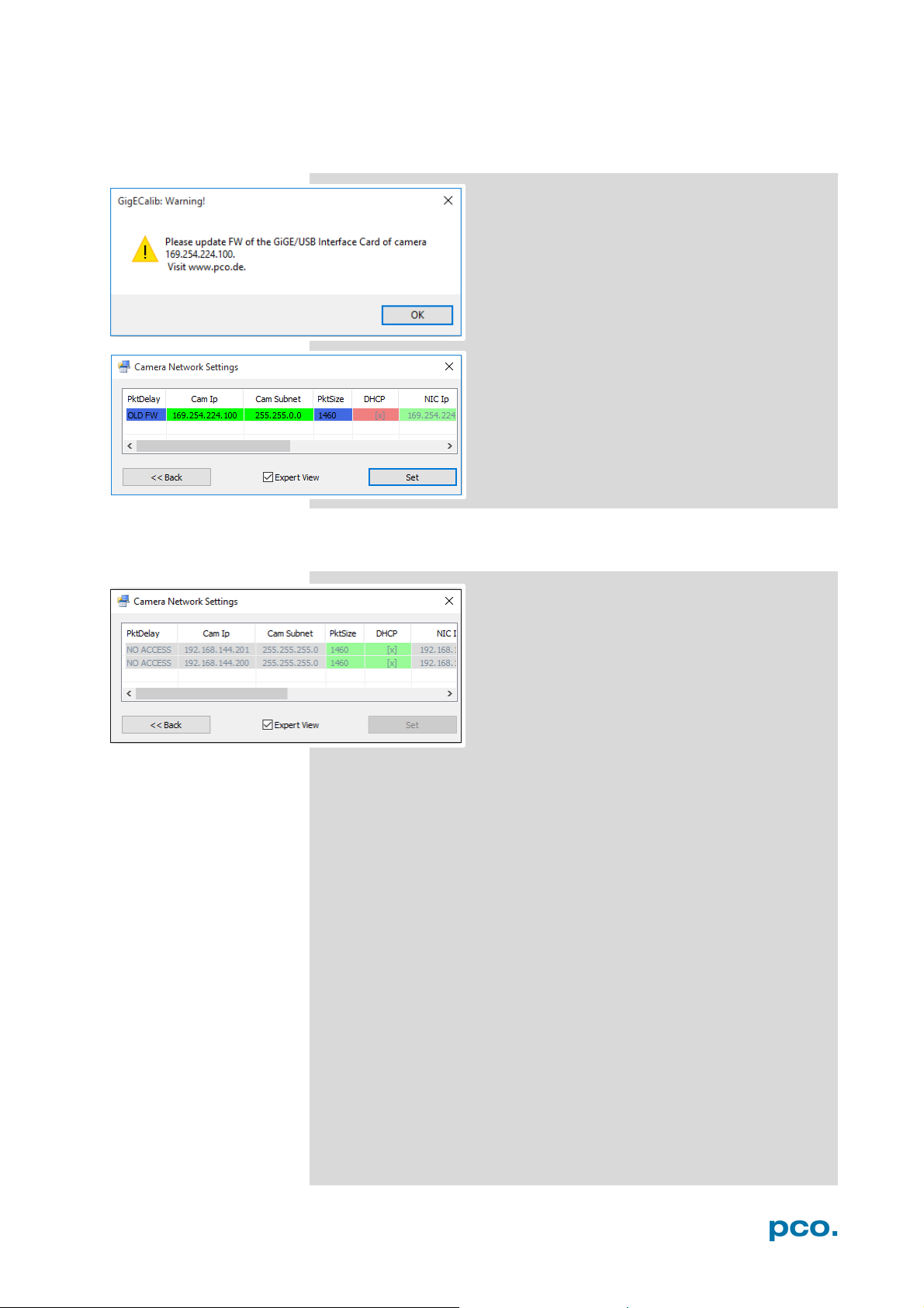
A2 GIGABIT ETHERNET INTERFACE
A2.5.1 FIRMWARE WARNING
A2.5.2 BLOCKED ACCESS
If this message pops up after clicking SET>> a
calibration will not be performed.
The driver needs a new firmware version to
work properly.
Download it from www.pco.de. Select Support
and your camera type.
If you can’t change the configuration (all fields
are grayed out) other software accesses the
camera (e.g. Camware).
Close all applications that directly access the
camera.
67
Page 68
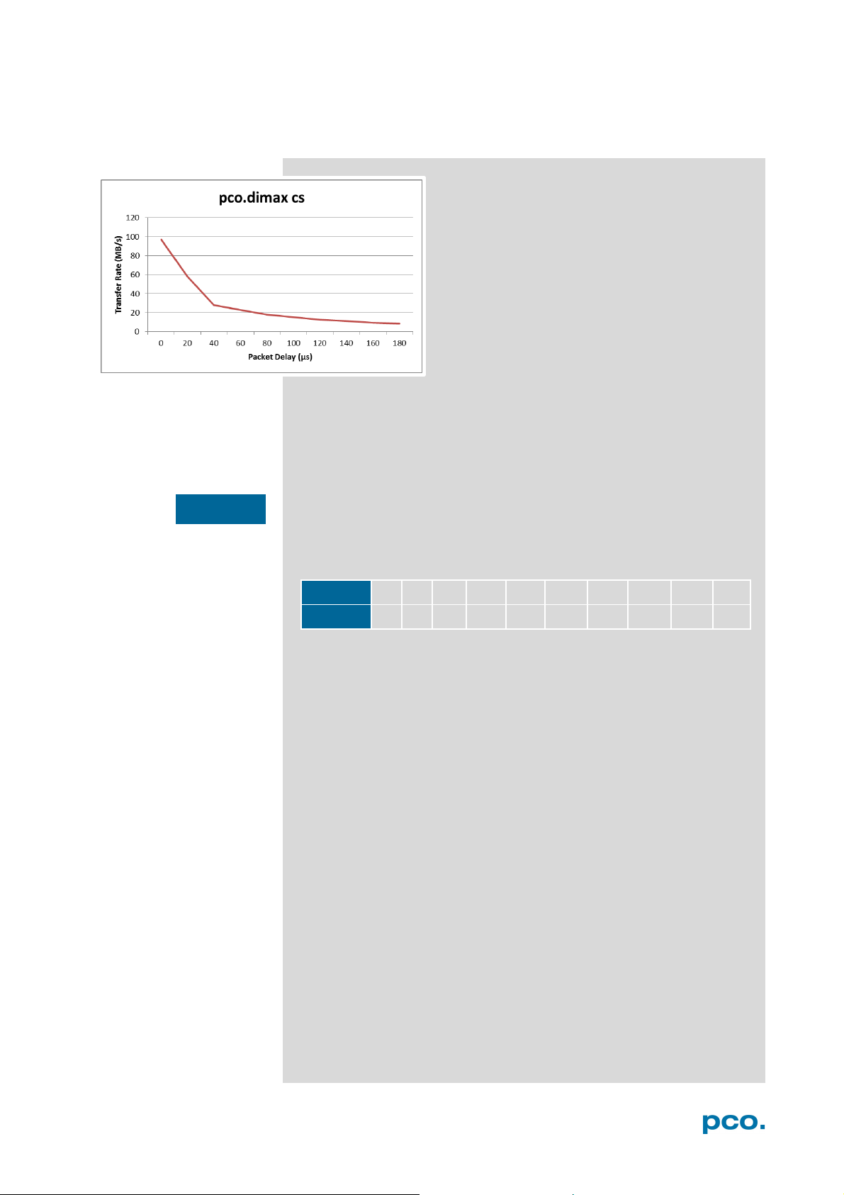
Delay/μs
0
20
40
60
80
100
120
140
160
180
MB/s
97
58
28
23
18
15
12.5
11
9.5
8.8
NOTICE
A2.5.3 NETWORK AND PACKET DELAY
The dialog Camera Network Settings sets the
Packet Delay and changes the PCO GigE
Camera network settings.
The Packet Delay value indicates the delay (in
µs) inserted between each ethernet packet of
the image payload data.
It is an approximate flow-control mechanism, if
the application or the network infrastructure
cannot keep up with the ethernet packets sent
by the device. A packet delay always slows
down data transfer rate.
Example: if two PCO GigE cameras are connected to a single Gigabit
Ethernet Port (for example via a network switch) the sum of the
bandwidths has to be smaller than the maximum possible data
transfer rate transmitted by GigE (100 MB/s).
If Packet Delay is increased, the data transfer rate is decreased.
Table Delay Time and transfer rate pco.dimax cs
68
Page 69
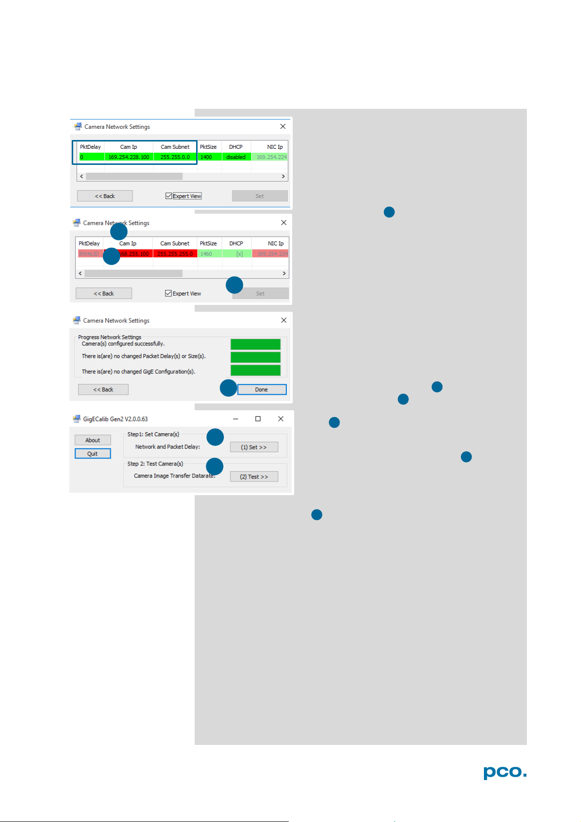
A2 GIGABIT ETHERNET INTERFACE
4
2 3 1 5 6
≫
2
3 4 1
5
6
A2.5.4 SET CAMERA IP ADDRESS & PACKET DELAY
Make sure the camera IP address (Cam IP) and
the camera network mask (Cam Subnet) fit to
the network interface card (NIC IP & NIC
Subnet) connected to. Everything is correct if all
values are highlighted in green.
If camera IP or subnet is not correct, it will be
highlighted in red . . The first three sections of
camera and NIC IP must be identical. The
fourth section between 1 and 254.
For example: NIC IP 192.168.144.49; a proper
camera IP would be 192.168.144.100.
The subnet mask must be exactly the same, e.g
255.255.255.0.
Set Packet Delay, standard is 40. Read A2.5.3
before setting the Packet Delay.
You can only change camera IP & subnet with
this tool, but not NIC IP & subnet (for NIC
configuration see A2.2.1).
Double-click onto the table to change the
value. Press the Set button to validate the
changings. After configuration is finished click
Done.
The next step is to check if IP and Subnet
configuration is correct: click Set
check if all values are highlighted in green.
Finally always Test≫ your settings. See chapters A2.5.5 and
A2.5.6.
again to
69
Page 70
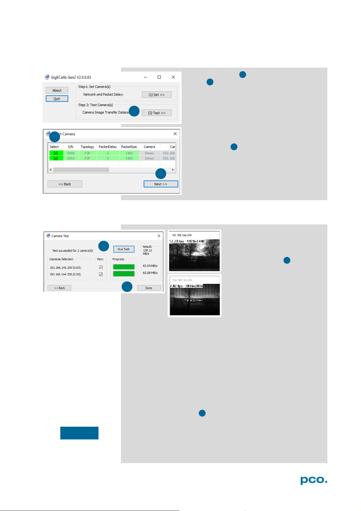
3
2
3
1
5 6 1
2
NOTICE
5 6 5
A2.5.5 IMAGE DATA TRANSFER RATE
First click Test≫ then double-click into the
Select column of the table to select the
camera. If a camera is not highlighted in green it
cannot be selected for testing. If more than one
camera is selected, they are going to be tested
in parallel.
Press Next >> button to open the Camera
Test dialog.
A2.5.6 CAMERA TEST
All cameras selected in the
Select Camera dialog are listed
here. If the View box is checked
the transferred images are
displayed. Click the Run Test
to start the Camera Transfer
Test. The test grabs images
from each camera listed – the
images from all camera are
transferred in parallel!
The whole Camera Transfer Test succeeds only, if each Single
Camera Transfer Test succeeds. With a Single Camera Transfer
Test 100 Images are transferred, and it fails, if more than 0.1% of all
transferred ethernet packets got lost.
If a Single Camera Transfer Test and so the Camera Transfer Test
for all connected cameras fails, first check the Packet Delay value.
It indicates the delay (in μs) inserted between each ethernet packet of
the image payload data.
The application or the network infrastructure cannot keep up with the
ethernet packets coming from the device. So, if a Single Camera
Transfer Test fails, increase the Packet Delay value (see A2.5.3).
Once finished click Done .
The Gen2 GigE maximum data transfer rate is about 100 MB/s. For a
pco.dimax camera with the Gen1 GigE interface card, the maximum
data rate is up to 68 MB/s.
70
Page 71
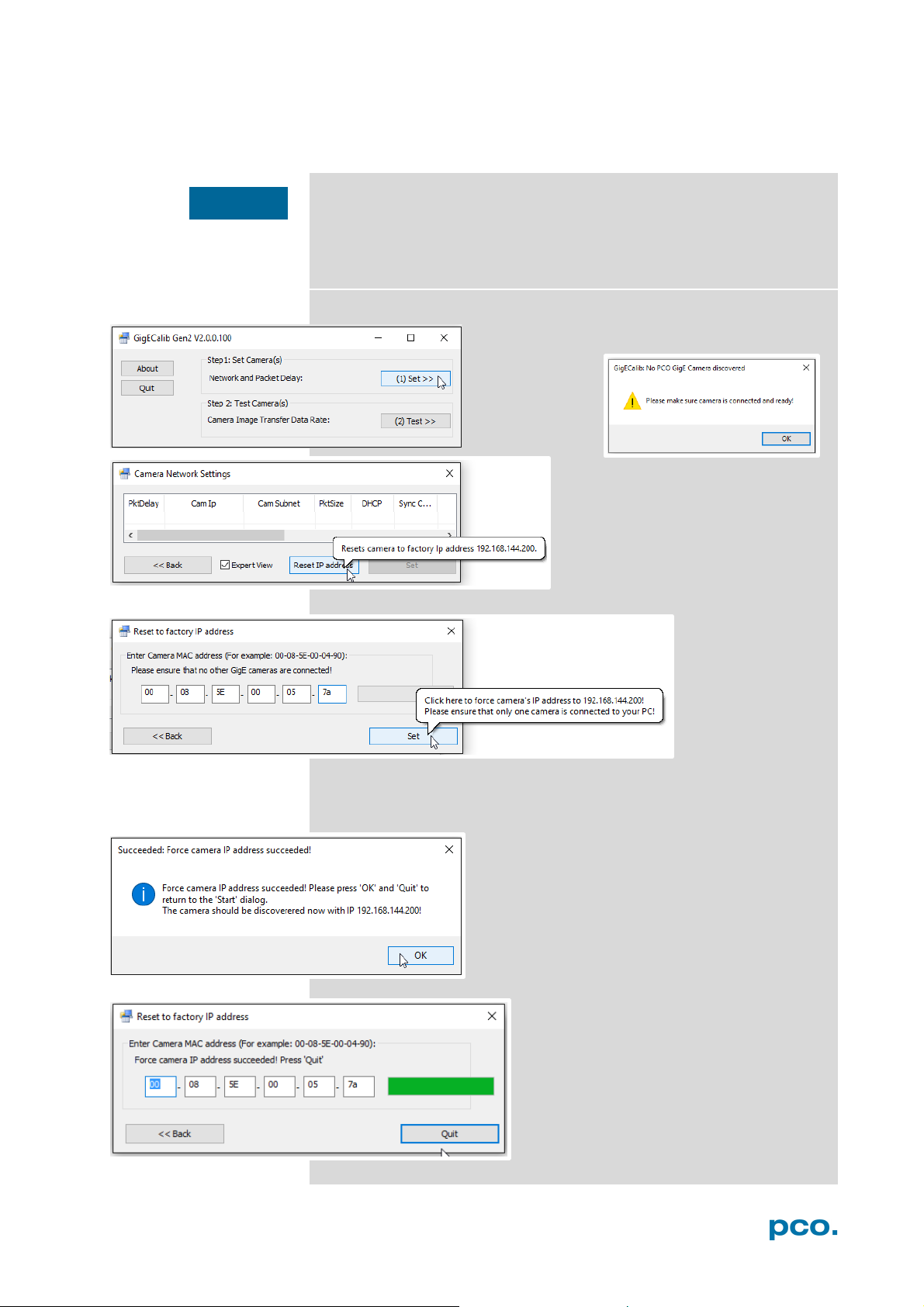
A2 GIGABIT ETHERNET INTERFACE
NOTICE
A2.5.7 RESET IP ADDRESS
This is a special function, which is not necessary for normal
configuration, but required if the camera is properly connected and
not found by the Calib Tool because of an incorrect IP address.
Only connect one camera to your computer, if you want to use this
function.
Press Set to reset the current IP address of your camera to the
factory default IP address.
Click Set. If Calib Tool can not find a correctly
connected camera an error will be displayed.
Reset IP address of your camera.
Enter MAC
address of your
camera (see
sticker on the
camera).
This window pops up after successful IP
address reset.
Press OK to return to the Reset to factory IP
address window.
Final step: press quit to return to the
Start Dialog.
Your camera should now be correctly
displayed and it is possible to continue
GigE configuration.
71
Page 72
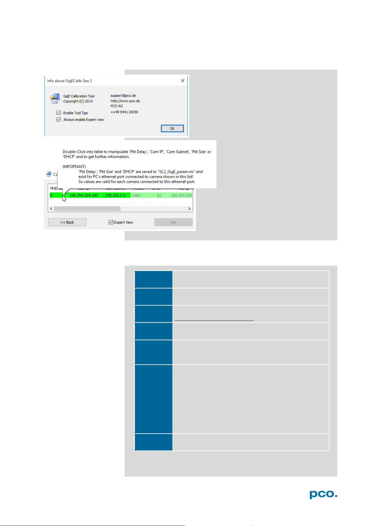
Firewall
If your camera is not recognized, deactivate Firewall
and Antivirus programs.
Driver (NIC)
Install original driver of your network interface card
(e.g. intel driver) assuring full performance.
Latest
Driver
latest PCO GigE driver (see
https://www.pco.de/support).
Buffer
Pay attention to the network interface card buffer
settings (see A2.2).
Firmware
If the Calib Tool tells to update the firmware,
for your
camera.
Slow data
If your computer has a network card installed (PCI /
or
): remove the NIC and select a different slot
the
lso check the wiring
,
the same problem can occur.
Windows
Install the latest windows updates. It prevents from
problems with the GigE driver installation
A2.5.8 TOOL TIPS
Enable / disable Tool Tips run the PCO GigE
Calibration Tool. Click the About button of the
Start Dialog and activate/deactivate the
Enable Tool Tips check box.
Enable Expert view: all setting options are
enabled.
Tool Tips helps to understand the
functionality of the calibration tool.
Packet Delay and other settings are
explained in detail.
HELP GUIDE A2.6
Always install the
download and install the latest version
transfer rate
(NIC)
PCI express slot) and the data transfer rate is slow
data transfer is only working with a high packet delay
(see A2.5.3
of your mainboard. Some slots may not reach
specified data transfer rate. A
diagram of your mainboard to select the fastest slot.
If you have a mainboard with e.g. two network ports
Update
72
Page 73
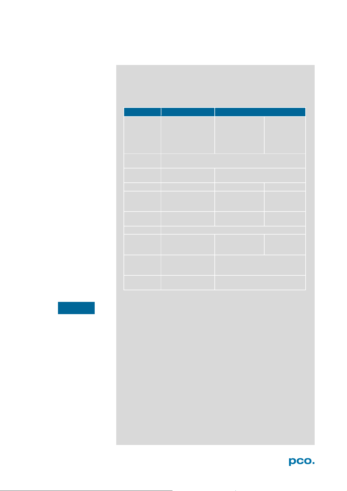
A2 GIGABIT ETHERNET INTERFACE
Minimum
Recommended
NIC
configuration
Network
connection
Patch cable
Cat5e
Cat5e or higher
TP Cat7e
Additional
switch, hub, router
Network
environment
virus protection/
firewall inactive
Driver
PCO GigE driver installed
Packet delay
mode
INTEL® Core™ i5
RAM
Operating
system
NOTICE
PERFORMANCE A2.7
The following table shows example configurations: minimum and
recommended ones. The specified values are only valid for these
configurations and should be an orientation.
Setup
Network
interface
card
(NIC)
network
components
/max speed
Computer
100 Mbps NIC with
standard PCI
interface
(only working with
GigE Gen2 driver)
Receive / transmit buffer is set to maximum
P2P or via switch P2P
are compatible to
100 Mbps
-
20 μs / off 0 μs / off 0 μs / off
CPU; 2.4GHz; 4GB
Win 7 – x64/x86 Win 7/8/10 – x64
GbE NIC with PCI
Express interface
Recommended
NIC see A2.2.3
no additional
components
INTEL® Core™ i7 CPU; >2.8GHz;
8GB RAM
10GbE NIC
Recommended
NIC see A2.2.3
no additional
components
Data transfer rate performance depends on sensor resolution.
73
Page 74
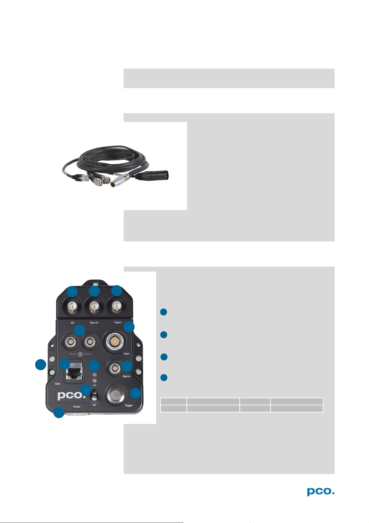
1 2 3
4 5 6 8 7
10
9
11
Pin1
12V out (±5%)
Pin3
n/a
Pin2
n/a
Pin4
GND
•
T0, Record stop,
Acquire trigger, TTL or Contact closure
single frame trigger (5kOhm after
1
2 3 4
12
A3 ACCESSORIES
Available accessories for pco.dimax cs camera systems.
BREAKOUT CABLE A3.1
Standard equipment for every pco.dimax cs
camera.
Connectors:
RJ-45 Cat.6 cable for GigE interface (3m)
• BNC Trig in (2m):
possible (5 kOhm after +5V)
• BNC Sync in (2m): TTL signal for sync.
or
ground)
• XLR cable for power supply (0.5m)
EXTENSION BOX A3.2
The pco.extension box is optional for the pco.dimax cs. It
manages all connection options of the camera system.
BNC: (50Ω cable required)
I/O: Input/Output: TTL status out/ busy or exposure
time (0 and 5V)
Sync In: TTL signal for synchronization or single frame
trigger (5kOhm after ground)
Trig In: T0, Record stop, Acquire trigger, TTL or
Contact closure possible (5 kOhm after +5V)
12V out: two 12V output connectors (1.5A each) for
external devices e.g. HD-SDI monitor; (input voltage ≥
15V)
Socket: Lemo EEG.0B.304.CLN (Fitting male connector:
FGG.0B.304.CLAD52Z)
74
Page 75
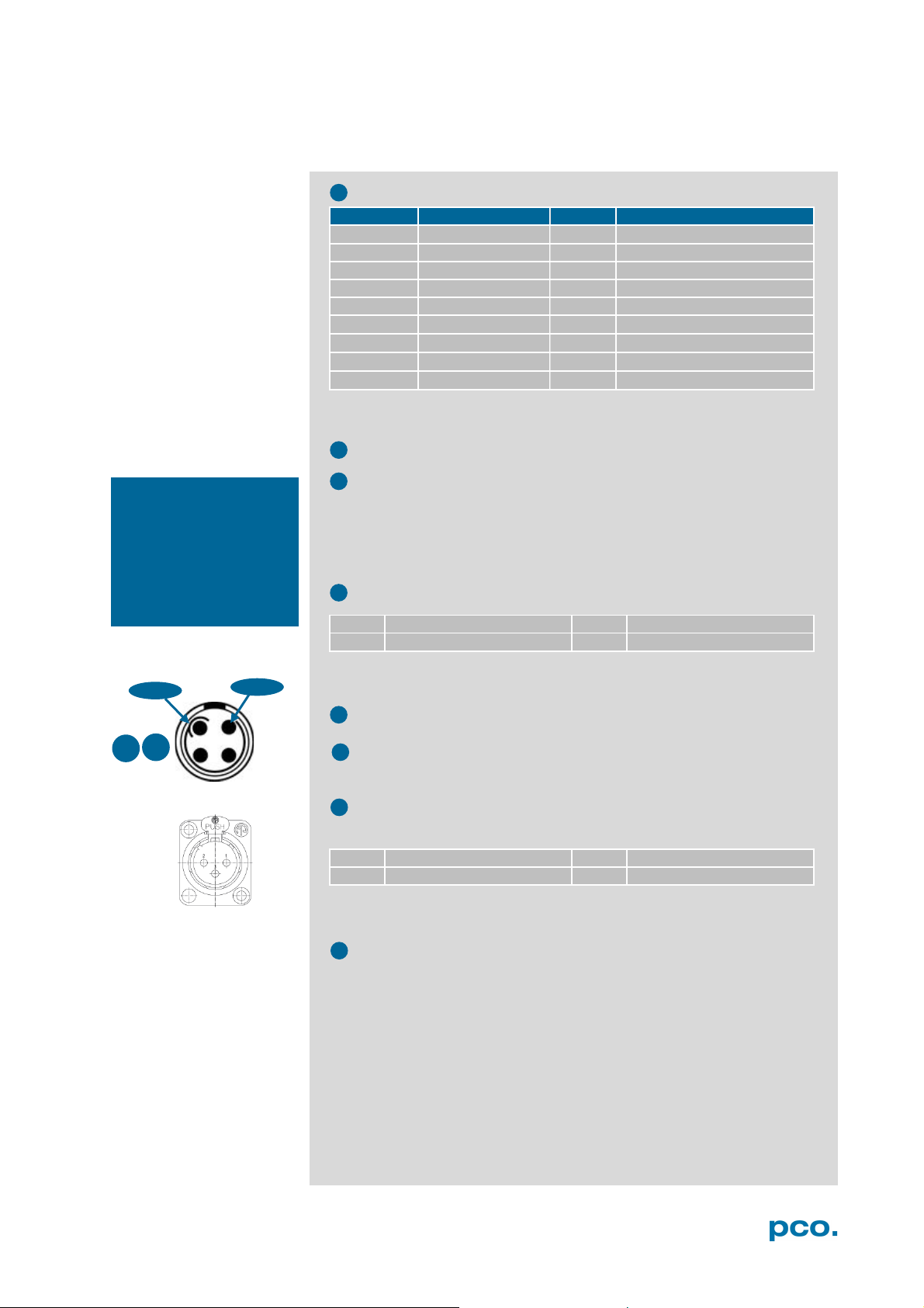
A3 ACCESSORIES
Pin
Function
Pin
Function
1
Ethernet A-
10
SYNC- (to BNC)
2
Ethernet D-
11
-SUP (GND)
3
Ethernet B-
12
-SUP (GND)
4
Ethernet B+
13
Ethernet A+
5
Ethernet C+
14
Ethernet D+
6
Status (to BNC)
15
Ethernet C-
7
+SUPPLY
16
Status (to BNC)
8
+SUPPLY
17
TRG+ (to BNC)
9
SYNC+ (to BNC)
18
TRG- (to BNC)
Pin1
External battery
Pin3
n/a
Pin2
pco.battery pack
Pin4
GND
Pin1
GND
Pin3
n/a
Pin2
+Voltage
Pin 1
Pin 4
8 5 7 9 6
10
11
NOTE
make sure signal
acquire enable (BNC
12
4
8
Using the Extension
box
polarity is inverted to a
TTL signal type at the
Trig In) input.
Cam: connection to camera; Lemo EEG.2B.318.CLN see A1.2
These BNC signals are transmitted differentially. Extension box
includes TTL to RS485 converters.
GigE: standard RJ45 Ethernet plug
LED:
Orange LED: voltage is applied
Green LED: power switch is set to on
Blue LED: green LED will change to blue for 2s if a trigger signal is
received
Batt In:
Socket: Lemo EEG.0B.304.CLN (Fitting male connector:
FGG.0B.304.CLAD52Z)
On/Off: pull this switch and then turn it up or down (Safety switch)
Trigger button: pushing generates an internal pulse (700μs) to the
Trig In BNC socket as OR gate.
Power: 12-48V XLR /Neutrik socket (fitting connector e.g.
NC3MX-BAG)
Power supply (provided): 24V 2.71A (65W) for 90/250 VAC
Mounting Threads: 2x M4, 3x ¼ inch, 2x M6 holes.
75
Page 76
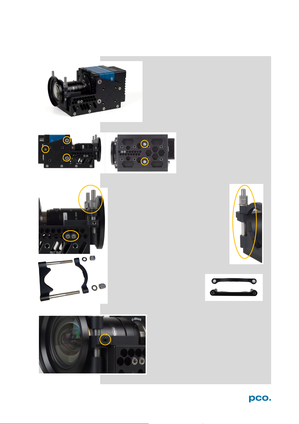
LENS CAGE A3.3
This cage is available for all pco.dimax cs models
and guarantees a stable mounting of camera and
C-Mount lens. PCO recommends the Lens cage
when strong acceleration forces can occur on the
lens. Contact PCO for further information and
matching lenses. An individual adaption to your lens
is possible.
Mounting threads to mount the lens cage to
your equipment:
Right side: 6x M6; Left side: 6x M6; Bottom: 8x M6
Mount the camera: use the two
hexagon socket (Allen) screws on
the bottom of the camera and the
three screws on each side to fix the
camera to the lens cage.
The height-adjustable lens holder
Mount the lens: use the two hexagon socket
(Allen) screws on each side and two screws on
the bottom to fix the lens holder to the cage.
The height adjustment can be adjusted by
vertical movement to the lens.
Then attach the clamping bracket and tighten it
with the two knurled screws. The knurled screws
must not be tightened with tools, as this could
damage the lens.
The lens holder must be installed so that the lens
is fixed without the moving parts being blocked.
The clamping bracket can be turned
by 180 degrees to clamp certain
lenses properly.
Hexagon socket (Allen) set screw: finally fix the
screw on both sides of the lens cage with a
tightning torque of 2.5 Nm.
76
Page 77
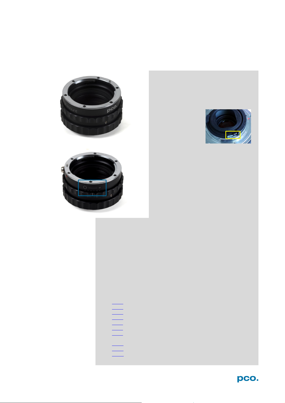
A4 MOUNT ADAPTER
Type 35mm F-Mount
• A012 -> SP 15-30mm F/2.8 Di VC USD
• F017 -> SP 90mm F/2.8 Di MACRO 1:1 VC USD
Type APS-C(H) F-Mount
• B001 -> SP AF 10-24mm F/3.5-4.5 Di II LD Aspherical [IF]
• G005 -> SP AF 60mm F/2.0 Di II LD [IF] Macro 1:1
A4 MOUNT ADAPTER
PCO F-MOUNT ADAPTER A4.1
This is the F-mount adapter from PCO.
If you have got a lens with automatic
diaphragm, this adapter allows you to easily
adjust the aperture by turning the aperture
ring on the adapter.
F-mount lenses
without an automatic
diaphragm can be
adapted to the
camera’s lens mount
but the aperture
cannot be set.
Adjust back focal length
Set the focus of your lens to infinity. After
that, look for an object in infinity and generate
a sharp image by turning the adapter. Use the
rearmost ring to fix the setting.
Matching lenses with automatic diaphragm:
Nikon: all Nikkor lenses of type D and type G (not for type E, this one
is only electronic).
Zeiss: all ZEISS ZF.2 lenses (Otus, Milvus, Interlock, Distagon,
Planar).
Sigma: only lenses, which already have a manual diaphragm ring; all
other lenses have an aperture control lever, which does not spring
back, if you turn the aperture ring at the adapter.
Tamron: only some lenses provide automatic diaphragm (no specific
lens family):
• A007 -> SP 24-70mm F/2.8 Di VC USD
• A009 -> SP 70-200mm F/2.8 Di VC USD
• A011 -> SP 150-600mm F/5-6.3 Di VC USD
• F012 -> SP 35mm F/1.8 Di VC USD
• F013 -> SP 45mm F/1.8 Di VC USD
• B005 -> SP AF 17-50mm F/2.8 XR Di II VC LD Aspherical [IF]
77
Page 78
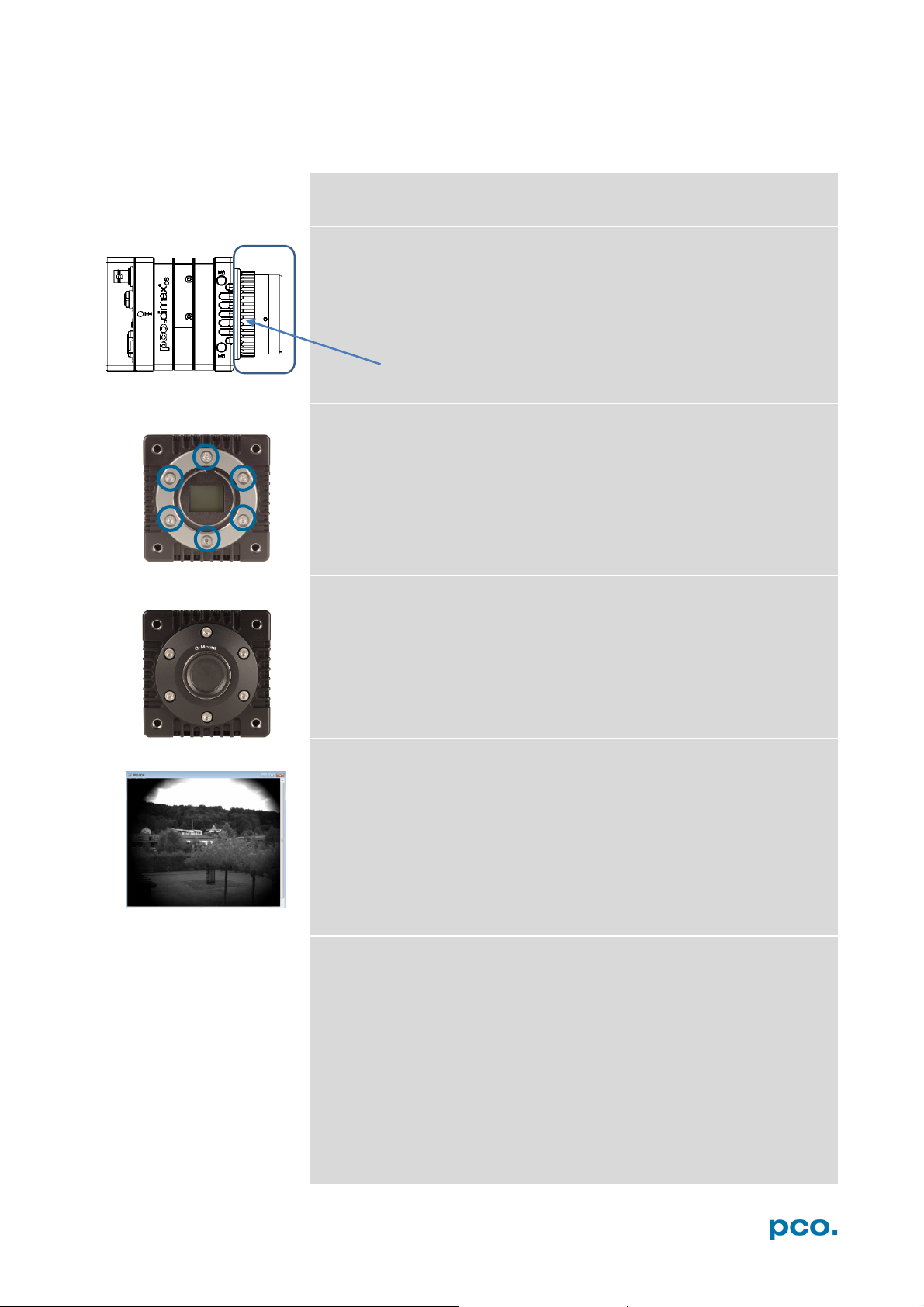
Counter ring
CHANGE F-MOUNT TO C-MOUNT / FOCAL DISTANCE A4.2
How to change the optical input from F-mount to C-mount:
Step 1: Remove F-mount Adapter
Grasp the F-mount adapter at the black ring (counter ring) and turn it
counterclockwise.
Step 2: Remove F-mount Ring
Unscrew these six Allen screws and carefully remove the F-mount
ring.
Step 3: C-Mount Adapter
Mount the C-Mount adapter with the six Allen screws.
Limitations of C-mount lenses
Keep in mind that C-mount lenses could produce shadings at the
edges of large sensors. Most C-mount lenses are able to illuminate a
maximum image circle of 11 mm (2/3”), 16 mm (1”) or 22 mm (4/3”)
diameter only. The pco.dimax cs cameras have a sensor diagonal
from 18.17 to 31.36 mm, thus you may have to use the ROI function
for a shadeless image while using C-mount lenses with smaller image
circles.
Adjust Back Focal Length
Adjust the back focal length (e.g. if you cannot focus to infinity or to
the minimum object distance of your lens), proceed as follows:
Install a lens and set it to infinity. Turn the rearmost black ring
counterclockwise until it is loose. Hold the black ring in position and
turn the front part of the F-mount adapter in any direction until the
image is sharp. Then turn the black ring clockwise to fix the position.
78
Page 79
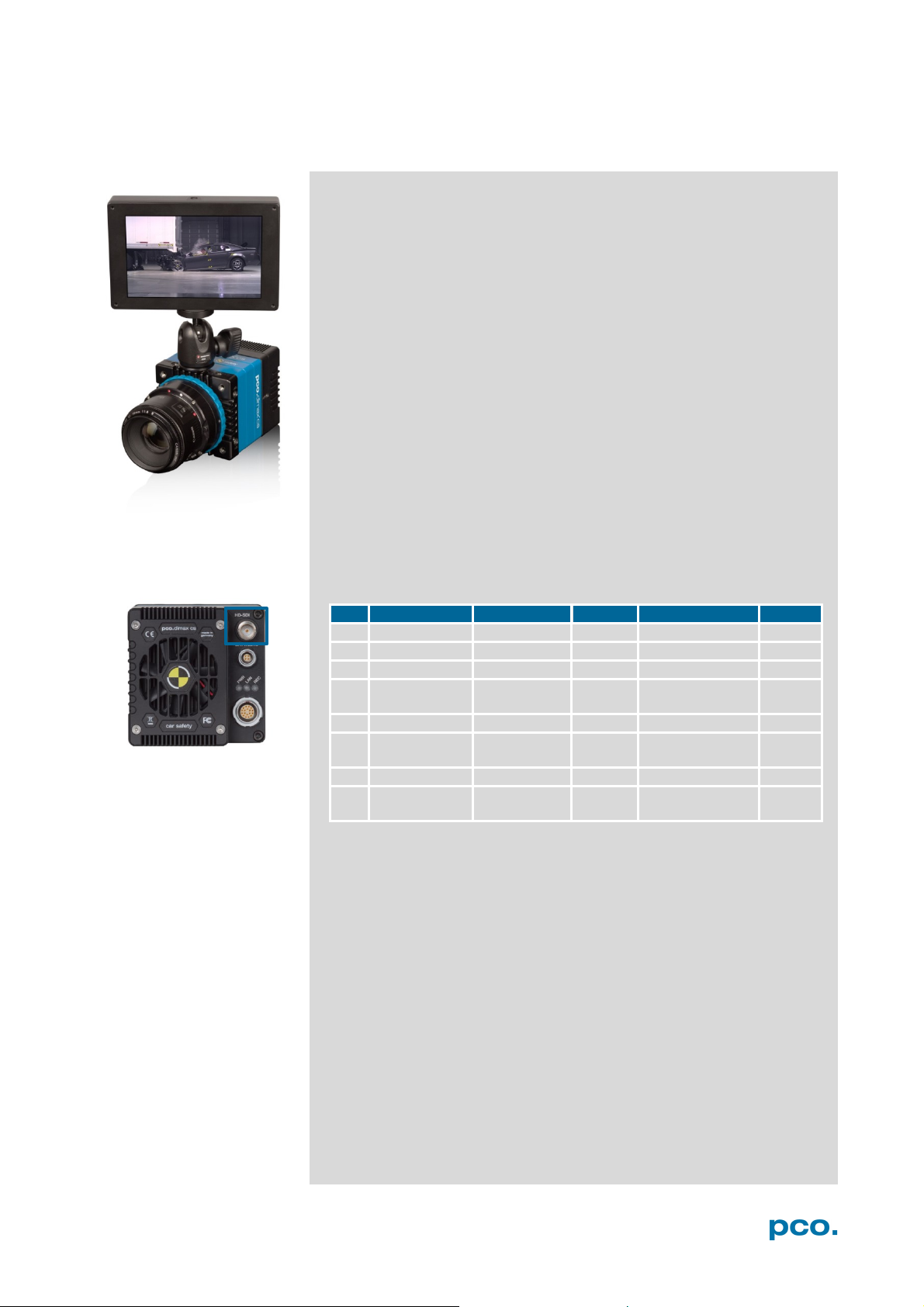
A5 HD-SDI
No.
Standard
Resolution
FPS
Mode
Format
1
SMPTE274M
1920 x 1080
25 fps
Single YCC10
PAL 7 SMPTE296M
1280 x 720
50 fps
Single YCC10
PAL
11
SMPTE274M
1920 x 1080
30 fps
Single YCC10
PAL
12
SMPTE274M
1920 x 1080
29.97
fps
Single YCC10
NTSC
13
SMPTE274M
1920 x 1080
24 fps
Single YCC10
PAL
14
SMPTE274M
1920 x 1080
23.98
fps
Single YCC10
NTSC
23
SMPTE296M
1280 x 720
24 fps
Single YCC10
PAL
24
SMPTE296M
1280 x 720
23.98
fps
Single YCC10
NTSC
A5 HD-SDI
HD-SDI is the High Definition Serial Interface and a special
standard of the film industry.
Features:
• 1x HD-SDI BNC connector (see A1.2)
• Required cable: 75 Ω coaxial BNC cable (RG59, Belden
1694A)
• It is only an output interface – control of the camera is not
possible!
• HD-SDI can only transfer certain resolutions and frame rates,
see table below
• The output is scaled so that the entire image appears on the
HD-SDI screen – no ROI restriction
• It can be used for e.g. an output monitor or a recorder
• No parallel image output in Camware and HD-SDI possible
• Bit rate: PAL: 1.485 Gbit/s; NTSC: 1.4835 Gbit/s; f
/1.001
f
PAL
NTSC
=
Overview of available formats:
79
Page 80
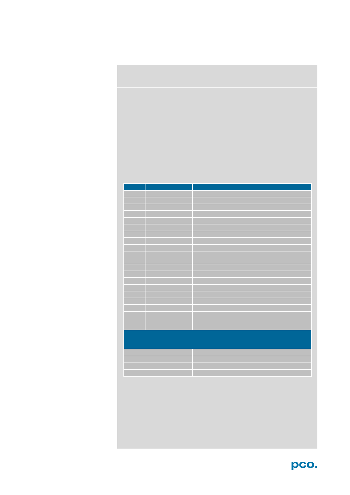
Parameter
Function
1
PCO-
the first 4 byte are the characters PCO-
2
file size
file size in byte
3
header length
header size + comment field in byte
4
image width
image width in pixel
5
image height
image height in pixel
6
extended header
-1 (true), extended header follows
7
color mode
0 = black/withe camera, 1 = color camera
8
b/w min
black/white LUT-setting, minimum value
9
b/w max
black/white LUT-setting, maximum value
10
b/w linlog
black/white LUT-setting,
11
red min
red LUT-setting, minimum value
12
red max
red LUT-setting, maximum value
13
green min
green LUT-setting, minimum value
14
green max
green LUT-setting, maximum value
15
blue min
blue LUT-setting, minimum value
16
blue max
blue LUT-setting, maximum value
17
color linlog
color LUT-setting, 0 = linear, 1 = logarithmic
18
Comment file in ASCII characters with variable length of 0…XX.
field.
16 bit pixel data
line 1, pixel 1
value of the first pixel
line 1, pixel 2
value of the second pixel
…
…
A6 IMAGE FILE FORMATS
There are different file formats available for saving camera images
with Camware:
b16
The b16 16 bit format is similar to the bmp format. However, 16 bit
pixel values are used instead of 8 bit pixel values.
The file format consists either of a Basic Header (6 Long-parameter)
or of an Extended Header (32 Long-parameter), the latter of which is
optional for additional information. It might follow a variable comment
field (ASCII code). Finally, there is the actual data set that is saved
linearly (as in the case of BMP files).
With the exception of the first value, all parameters are Long Integers
(4 Byte). The first six parameters must always exist. The rest of the
parameters, as well as the comment field, are optional.
266
The length of the comment field must be documented in the header length
internal use
W
W
e
PCO recommends that all images should be saved first in the b16
or TIFF format. The advantage is to have the b16 or tiff images
available all the time, having the maximum 16 bit information. Note
that not all image analysis programs can accommodate 16 bit data.
The 8 bit format saves only the information displayed on the monitor
screen. The 16 bit information will be lost and cannot be recovered.
0 = linear, 1 = logarithmic
80
Page 81
A6 IMAGE FILE FORMATS
pcoraw
This 16 bit PCO file format is based on the BigTIFF format, thus
allowing for file size > 4GB. A new PCO proprietary compression
scheme is added if necessary.
Standard File Formats
TIFF
Tag Image File Format, version 6.0 and lower. There is a 16bit
monochrome and color image format.
BMP
Windows Bitmap Format, b/w or color 8 bit format images, which
have been saved in BMP format can’t be reloaded in Camware - only
as 8 bit images, i.e. part of the original information (16 bit) is lost.
FTS
Flexible Image Transport System, Version 3.1. There is a 16 bit image
format defined by the NASA/Science Office of Standards and
Technology (NOST). Some programs use the FIT extension for this
format.
ASCII
16 bit format, some mathematical programs prefer ASCII data.
JPG
JPEG (named after the Joint Photographic Experts Group who
created the standard) is a commonly used method of lossy
compression for photographic images. The degree of compression
can be adjusted, allowing a selectable tradeoff between storage size
and image quality.
JP2
JPEG 2000 is a wavelet-based image compression standard and
coding system. It was created by the Joint Photographic Experts
Group committee in the year 2000 with the intention of superseding
their original discrete cosine transform-based JPEG standard
(created 1992).
AVI
Audio Video Interleave is a multimedia container format introduced by
Microsoft in November 1992 as part of its Video for Windows
technology.
MPG
MPEG-1, similar to JPEG, is a standard for lossy compression of
video and audio developed by the Moving Picture Experts Group
(MPEG).
WMV
Windows Media Video (WMV) is a compressed video format for
several proprietary codecs developed by Microsoft. The original video
format, known as WMV, was originally designed for Internet
streaming applications, as a competitor to RealVideo.
81
Page 82
NOTICE
CAUTION
NOTICE
NOTICE
NOTICE
A7 CUSTOMER SERVICE
SERVICE A7.1
The camera is designed to operate with no need of special
MAINTENANCE A7.2
adjustments or periodic inspections.
UNPLUG CAMERA BEFORE CLEANING
Risk of injury due to electrical shock!
Unplug the camera from any power supply before cleaning it.
CLEANING
Use a soft, dry cloth for cleaning the camera.
Do not clean the input window unless it is absolutely
necessary.
Be careful and avoid scratches and damage to the input
window surface.
Do not use liquid cleaners or sprays.
LENS CLEANING
The lens is best cleaned with pressurized air or with liquid
cleaners such as pure alcohol or with special optical
cleaners that are available at premium photo stores.
Use a cotton swab dipped in pure alcohol or optical cleaning
liquid and wipe only on the glass surface.
Do not get any cleaning liquid on the metallic parts such as
the lens thread, because tiny detached particles may scratch
the surface.
CLEANING LIQUIDS
Aggressive cleaning liquids can damage your camera.
Never use aggressive cleaning liquids such as gasoline,
acetone, spirits or nitro cleanser.
Every time the input window is cleaned, there is the
possibility of surface damage.
PROTECTIVE CAP
Always store the camera with the protective cap or with a lens
mounted to avoid dust and dirt on the input window.
RECYCLING A7.3
To dispose your camera, send it to PCO or take it to a local
recycling center.
The camera includes electronic devices, which can contain materials
harmful to the environment. These electronic devices must be
recycled.
82
Page 83
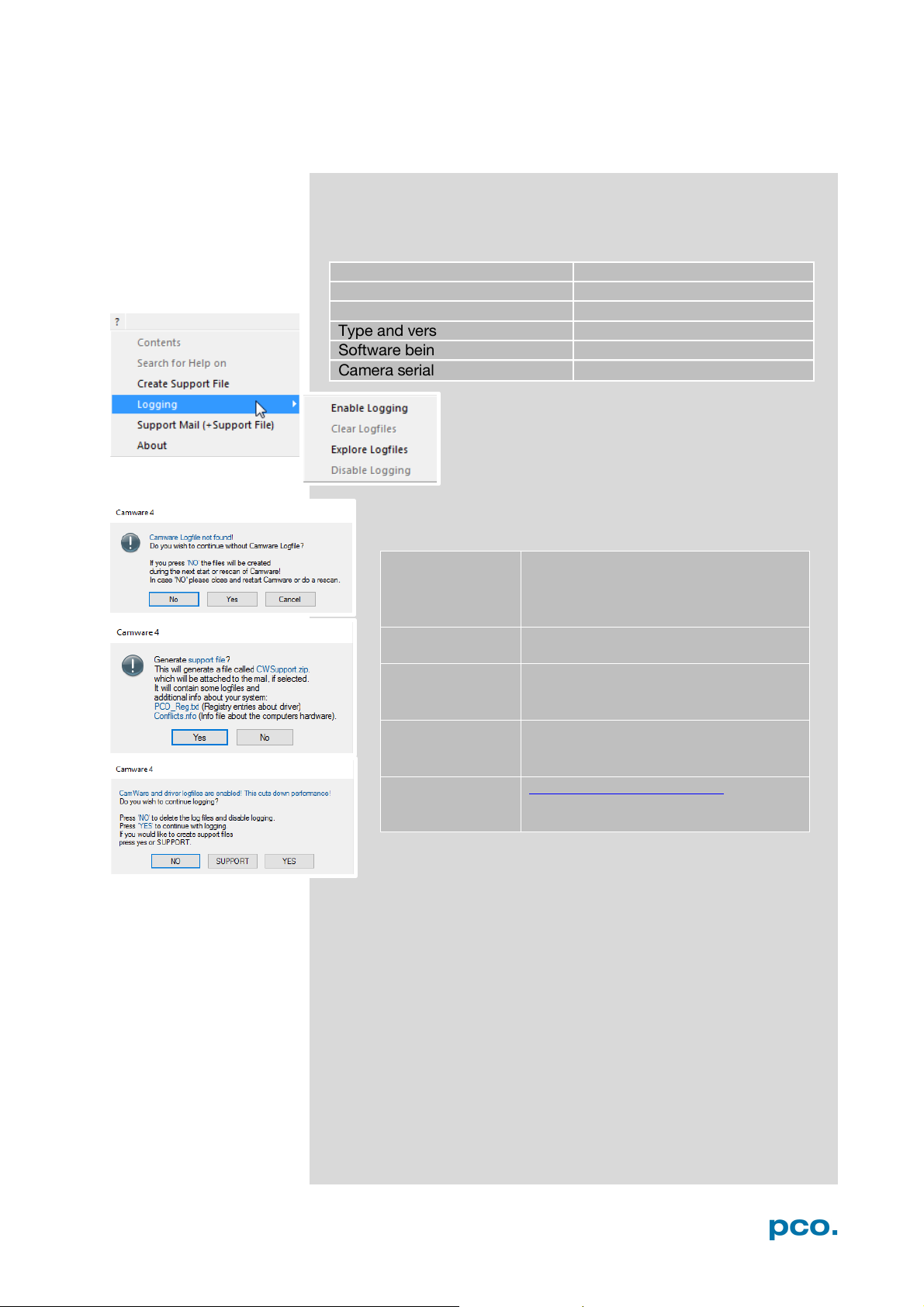
A7 CUSTOMER SERVICE
Short description of the problem
Operating system (PC)
Description of your application
Processor type (PC)
Camera settings
Memory
Type and version of camera
Graphic card
Software being used
Graphic card setup
Camera serial number
Enable log files:
? Help Menu → Logging → Enable
restart of Camware
Repeat
the workflow which produces the
faults
Open the Help
Click Support Mail (+ Support File) →
support file?
Save this file
(CWSupport.zip – don’t rename it)
Or visit our
http://www.pco.de/support/ and
support form
LOGFILE / SUPPORT FILE A7.4
If you have a question, which is not adequately addressed in this
manual, contact PCO or your local dealer.
To speed your request up, we need following information:
How to create a logfile:
Logfile →Camware will ask you to
press NO to activate Logfiles after
Menu
Camware will ask you: Generate
and send it to PCO Support
website:
upload the support file with our
Repair
Before sending the camera for repair, first contact your local dealer
or PCO respectively.
When shipping the camera for repair, be certain to carefully pack the
camera with proper shipping materials. If possible use the original
packaging. Use the protection cap to protect the camera on the lens
thread.
83
Page 84

TROUBLE SHOOTING A7.5
Communication problems (camera is not detected)
• Take a look at the LEDs and note their state
• Disconnect and reconnect your interface , then wait (about 1 min)
for Beep and start Camware camera search again
• If this does not work –test another interface
o Restart your camera by plugging off /on power supply: look
at LED sequence and note their state
o all LEDs are off for several seconds (if the break time was too
short, it might be that last LED status is shown again)
o all LEDs light up (red, green and blue)
o green LED is blinking for several seconds, then green
continuous, all other LEDs off
o red LED means initializing failed
• Show us your log-files including extra information (any other
abnormalities / camera equipped with a battery?)
Image Error (e.g. quadrant error)
Describe your error (send us a Raw B16 or TIFF screenshot)
Fan control
The pco.dimax has a fan control. After starting or restarting camera
fan runs with highest rotation (noisy) and should slow down after
about 30s.
GigE-Connection
After start-up or (re)connection of GigE cable or by pushing the resetknob at the rear of the pco.dimax, the connection of the GigE
interface will be reestablished.
A short beep just confirms the physical network connection, not a
pco driver linkage; although an operating network connection is
indispensable for the driver.
Repeating beeps signalize a defective cable, communication is
interrupted.
Firmware, Software and Driver Update
You will find all necessary software and drivers on the accompanying
USB flash drive.
For the latest versions check our website:
http://www.pco.de/support/supportProducts/high-speed-cameras/
84
Page 85
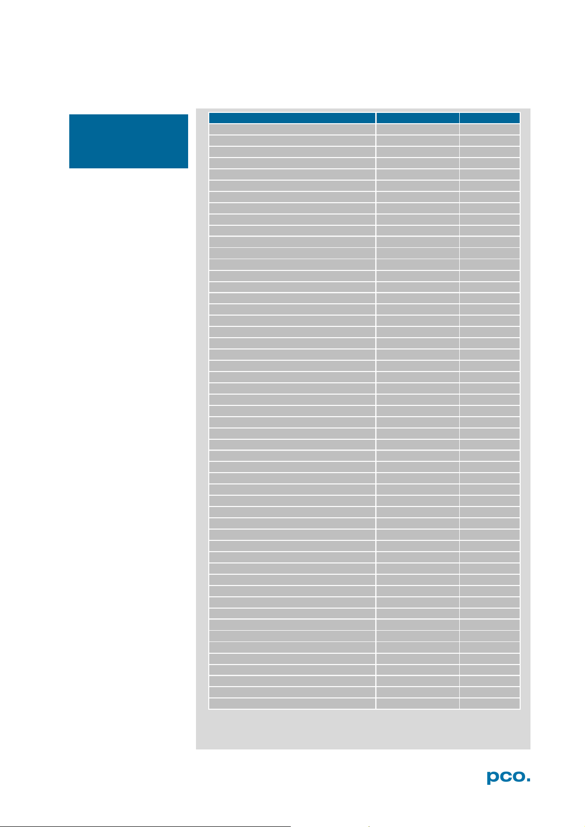
A8 INDEX
Key word
Chapter
Page
Auto Save Mode
6.8.1
39
Averaging
6.5
33
Acquire mo de
6.3.5
24
C-mount change
A4.2
78
Cable length
A2.2.2
60
Camware software
6
14
Codec Dialog
6.9.2
42
Connection options
A1.4
53
CDI mode
6.3.3
23
Contrast settings (Convert control)
6.3.8
30
Cuda (nvidia) driver
4.1
9
Data sheet
A1.1
52
Demo mode (Camware)
6.9.1
41
Dimensions
A1.3
54
Direct record to file
6.9.2
42
Double image mode
6.3.3
23
Driver installation
4.2 ; A2
10; 57
Extension Box
A3.2
74
File formats
A6
80
Focal distance
A4.2
78
Frame rate
6.3.1
18
GigE configuration
A2
57
IIR low pass filter
6.5
33
Image Overlay
6.4
32
Input / Output possibilities
6.3.7 ; A1.2
28; 53
Interface
A2
57
Internal Memory
6.3.4
24
Lemo Connector
A1.2
53
Logfile
6.9.7
47
Live preview
6.9.4
45
Master Settings
6.2
15
Mount change
A4.2
78
Options
6.9.2
42
Preview
6.2
15
Rear connections
A1.2
53
Recorder modes
6.3.5
24
Recorder me mory
6.3.4
24
Recycling
A7.3
82
Region of interest (Sensor ROI)
6.3.2
22
Rescan for cameras
6.9.3
44
ROI window
6.3.2
22
S
2
7
Save / Open / Print files
6.9.2
42
Settings Overview
6.8
38
Sequence trigger mode
6.3.5
24
Short Cut List
6.9.9
50
Support
A5
82
Synchronization
6.3.1
18
Time stamp
6.3.5
24
Timing
6.3.1
18
Trigger Mode
6.3.1
18
White Balance
6.9.9
48
NOTE:
always the starting
page of a chapter!
A8 INDEX
The mentioned page is
afety instructions
85
Page 86
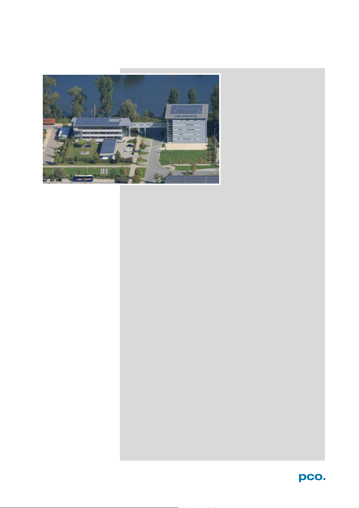
ABOUT PCO
pco.
ABOUT PCO
In 1987, PCO was founded with the objective to develop and to
produce specialized fast and sensitive video camera systems, mainly
for scientific applications. Meanwhile the product range of PCO
cameras covers digital camera systems with high dynamic range,
high resolution, high speed and low noise, which are sold in the
scientific and industrial market all over the world.
Currently PCO is one of the leading manufacturers of scientific
cameras. Worldwide representatives, together with our own sales
department and technical support assure that PCO keeps in touch
with our customers and their needs. The actual wide range of
specialized camera systems is the result of technical challenge and
product specific know-how. A design according to advanced
techniques, a high standard of production and strict quality controls
guaranty a reliable operation of the cameras. Our own developments
in conjunction with an excellent contact to leading manufacturers of
image sensors ensure our access to state-of-the-art CCD- and
CMOS-technology for our cameras.
Since 2001, PCO is located in its own facility building in Kelheim at
the shore of the beautiful and international river Danube. Here in the
county Bavaria, which is well known for its excellent support and
conditions for high technology companies, we share the benefits of
the simple access to high performance products and services in the
surrounding area.
Kelheim itself is a historical town, first documented in 866. The small
city is founded at the confluence of the Danube and the Altmühl,
which has been converted into the Rhine-Main-Danube bypass
channel for water transport. Located in Danube-valley, it is the heart
of a beautiful river and forest covered lime plateau landscape. It´s
landmark, the Hall of Liberation, was built by Ludwig I. in 1863 on the
Mount Michael and is visible from all over the city and valley. The
beautiful Danube-Gorge, which is protected as natural monument
since 1840, is located between Kelheim and the famous abbey
Weltenburg.
86
Page 87

pco.
 Loading...