

Page 1
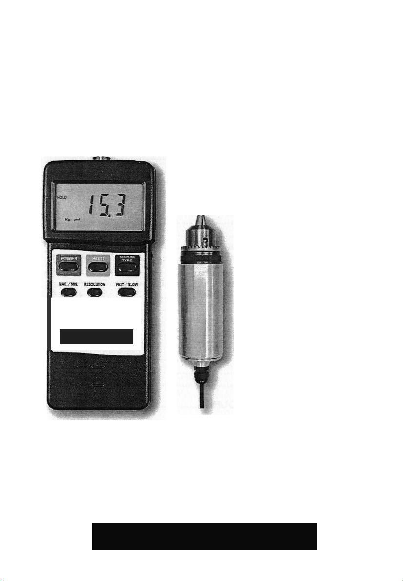
15 Kg-cm
-
1'6,C
-
ttllO
-
,_HfT
TORQl;E METER
TORQUE METER
Your purchase of this T O R Q U E M E T E R
TACHOMETER marks a
step forward for you into
the field of precision
measurement. Although
this TORQUE METETR is a
complex and delicate
instrument, its durable
structure will allow many
years of use
operating techniques are
developed. Please read
the following instructions
carefully and always keep
this manual within easy
reach.
if
proper
OPERATION MAN UAL
Page 2

TABLE OF CONTENTS
1.
FEATURES ...................................................... 1
2.
SPECIFICATIONS .......................................................... 1
2-1
General Specifications ........................................... 2
2-2
Display Unit/Max. range/Resolution ..................... 3
3.
FRONT PANEL DESCRIPTION ..................................... 4
3-1
3-2
3-3
3-4
3-7
3-8
3-1O Fast/Slow
3-11
3-13
3-14
3-15
3-16
3-17
3-18
Display ..................................................................... 4
Power Button ...................................................... 4
Hold Button ......................................................... 4
" Max./Min. " Button ............................................. 4
3-5
3-6
Resolution Button ............................................... 4
Sensor Type Button ............................................ 4
3-9
Battery Compartment/Cover. ............................. 4
3-12
RS-232 0utput Terminal. ............................... 4
Sensor cable plug.............................................. 4
Torque Sensor Body ......................................... 4
Gear ..................................................................... 4
Cramp .................................................................. 4
Pinion ................................................................... 4
Unit Button .......................................... 4
Peak Button ........................................ 4
Zero Button ......................................... 4
Button ................................................ 4
Sensor Input Socket. .......................... 4
4.
MEASURING PROCEDURE .......................................... 5
5.
AUTO POWER DISABLE ............................................... 9
6.
RS232 PC SERIAL INTERFACE
7.
BATIERY REPLACEMENT ............................ 11
8. OTHER OPTIONAL ACCESSORIES .............. 11
.......................................... 9
Page 3
Display
61 mm x 34 mm supper large LCD display.
15 mm ( 0.6" ) digit size.
Measurement
Torque value, peak value hold,
data hold, Max. & min. value.
Unit
Kgf-cm, LBf-inch, Newton-cm.
Maximum
range
15 Kgf-cm,
147.1 N-cm.
* N = Newton
1.
FEATURES
*
Professional torque meter with 15 Kgf-cm torque probe,
full set.
*
3 kind display unit select button of Kgf -cm, LBf -inch
and Newton -cm on the front panel.
*
Data hold button to freeze the desired reading.
*
Peak measu rement to hold the peak valu e.
*
Selecting the high resolution or low resolution.
*
Fast or Slow sampling time selecting by push button.
*
Record Maximum and Minimum readin gs with recall.
*
RS 232 computer interface.
*
Super large LCD display, easy readout.
*
Microcomputer circuit, hi gh performance.
*
Separate torque probe, easy operation.
*
Auto power off saves battery life.
*
Built
*
Heavy duty & compact housing case.
*
Complete set with the hard carrying case.
-in
low battery indicator.
2.
SPECIFICATIONS
·
ri1·
2-1 GeneraI
measurement
;pee,
S
13.02 LBf-inch,
cat
1ons
1
Page 4
2
Accuracy
±
(
1.5 % + 5 d )
Resolution
High resolution
0.1 N-cm
*
N = Newton
Low resolution
1
N-cm
*
N = Newton
Sensor
Exclusive torque sensor.
Circuit
Exclusive microcomputer circuit.
Data hold
Freeze the desired readinq.
Peak hold
To hold the peak value.
Memory
Maximum & Minimum value .
Overload
22.5 Kgf-cm max.
220.1 N-cm max.
Power off
Auto shut off, saves battery life,
or manual off by push button.
Sampling time
Fast/Slow select.
Slow : Approx. 0.334 second.
Data output
RS 232 serial output.
Operating
temperature
O
c
to 50
°C ( 32 °F to 122 °F ).
Operating
humidity
Less than 80% RH.
Power supply
Alkaline or heavy duty type
MN1604 (PP3) or equivalent.
Power
consumption
Approx. DC 12 mA.
Weight
Meter
I
225 g ( 0.50 LB ) .
Probe
1
665 g ( 1.46 LB ).
0.01 Kgf-cm
0.01 LBf-inch
capacity
0.1 Kgf-cm
0.1 LBf-inch
19.53 LBf-inch max.
Fast : Approx. 0.125 second.
0
DC 9V battery, 006P,
Page 5
3
Dimension
Meter :
( 7.1 x 2.8 x1.3 inch ) .
Torqueprobe:
Round 48 mm Dia. x 160 mm.
Accessories
* Instruction manual.................... 1 PC.
* Carrying Case...........................1 PC.
Optional
* Software ( Windows version,
.....................................SW-U101-WIN
* RS232 cable
.....................................UPCB-01
Display unit
Max. range
High resolution
Kg cm
15 Kgf-cm
0.01 Kgf-cm
LB inch
13.02 LBf-inch
0.01 LBf-inch
N ern
147.1 N-cm
0.1 N-cm
Unit Max. range
Low resolution
Kg cm
15.0 Kgf-cm
0.1 Kg-cm
LB inch
13.0 LBf-inch
0.1 LB-
inch
N ern
147 N-cm
1 N-cm
180 x 72 x 32 mm
included
* 15 Kg torque probe...................1 PC.
* Pinion........................................1 PC.
accessories
data record & data
acquisition )
2-2
Display Unit/Max. range/Resolution
*
N = Newton
Page 6
4
3-
1
8
,
0
3.
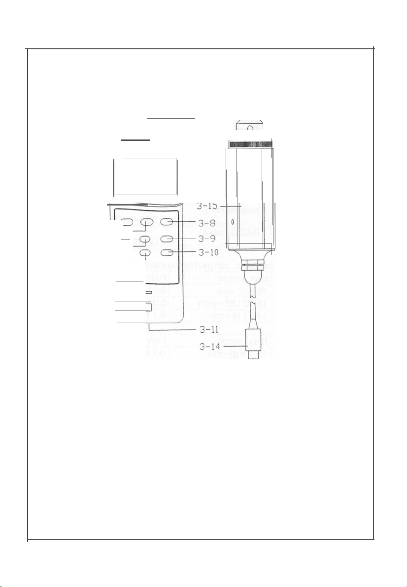
FRONT PANEL DESCRIPTION
3-1
+----,
3-1 -l--
3-2
3-3 --H----'
3-4
3-5
3-6
3-7
--t
Fig. 1
-l+-
..
,
--H-sc
--+t---L-. )
---+if-----'
-+---c_J
--H-
OD
3-17
3-12 3-16
3-15
3-8
3-9
3-10
3-1
Display
3-2
Power Button /Cover
3-3
Hold Button
Button
11
Button
3-4
3-5
3-6
3-7
3-8
11
Max./Min.
Unit Button Terminal
Peak
Resolution Button 3-15 Torque Sensor Body
Sensor Type Button
3-9
Zero Button
3-10
Fast/Slow Button 3-18 Pinion
3-11
3-12 Sensor Input Socket
3-13
3-14
3-16
3-17 Cramp
Battery
RS-232
Sensor
Gear
Compartment
Output
Cable
Plug
Page 7
5
•
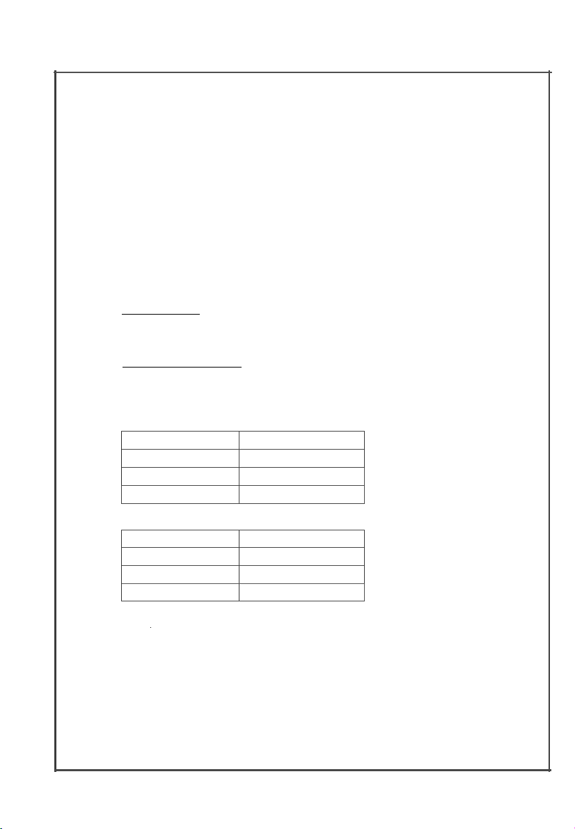
Display unit
Resolution
Kg cm
0.01 Kgf-cm
LB inch
0.01 LBf-inch
N ern
0.1 N-cm
Display unit
Resolution
Kg cm
0.1 Kg-cm
LB inch
0.1 LB-inch
N ern
1 N-cm
4.
MEASURING
1) Plug in the " Sensor Cable Plug " ( 3-14, Fig. 1) to
meter's " Sensor Input Socket
2) Power on the meter by push the
3) Push the " Sensor Type Button
the meter's sensor type is same as the external torque sensor.
Push
the
IISensor Type Button ':the LCD will show
11
15 Kg cm
4) Unit Button
Push the " Unit Button
Kgf
-cm,
LBf -inch or N-cm ( Newton -cm ).
5) Resolution Button
Push the
II
Resolution Button " ( 3-7, Fig. 1) to select the
High resolution or Low resolution.
PROCEDURE
11
11
11
(
3-12,
Fig. 1).
II
Power Button
11
(
3-8,
Fig 1) to check if
(
3-5,
Fig. 1 ) to select the unit
11
(
3-2,
Fig. 1 ).
Set
ect
Select low resolution
6) Fast/Slow Button
The " Fast/Slow Button " ( 3-10, Fig. 1 ) is used to select
the fast sampling time or slow sampling time.
*
Fast
* Slow sampling time, display will show the " S " indicator.
h"1gh
resoI utt•on
sampling time,
display will show the
* N = Newton
*
N = Newton
IIF IIi
ndi
cntor.
Page 8
6
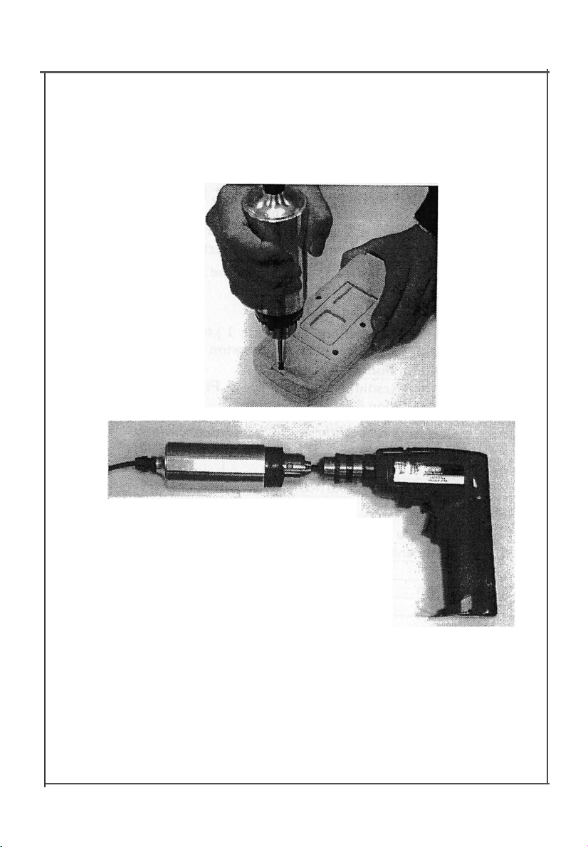
To screw the probe on the table
hold the probe
assuredly.
t
7) To connect the " Cramp " ( 3-17, Fig. 1 ) to the measure d
installation and use the " Opinion " ( 3-18, Fig. 1) to lock
the " Gear " ( 3-16, Fig. 1). Ref. Fig. 2
&
Fig. 3.
Fig. 2
or use the vise to
Fig. 3
Page 9

8) Zero Button
Before the measurement,
value, it can push the
tare the display value, the LCD
9) Apply the torque force, the LCD will show th e measured torque value.
10) Peak hold
During the measurement, push the
Fig. 1), the LCD will show the
display will hold the peak value.
Remark :
Under the peak hold function , the sampling time
define to "Fast sampling
11
F "indicator.
11) Data Hold
During the measurement, pushing the
( 3-3, Fig. 1 ) will freeze the measured value & display will
indicate
to release the data hold function.
12) Data Record ( Maximum, Minimum reading )
*
The DATA RECORD function displays the maximum
and minimum readings. To start the DATA RECORD
function, press the
once.
*
With the
(a) Push the
if
the meter not show zero
II
Zero Button
will
change to zero value.
II
PEAK
"& the disiplay will show the
II
HOLD
ti
symbol. Push the
II
Max./Min. Button
11
REC
ti
symbol will appear on the LCD display.
II
once, the
II
REC
symbol on the display :
ti
Max./Min. Button
II
II
Max
symbol along with the maximum
value will appear on the display.
11
(
3-9, Fig. 1) to
II
Peak Button
II
indicator & the
II
Hold Button
II
Hold But ton
ti
(
3-4,
ti
(
3-4,
Fig. 1 )
ti
(
3-6,
wJ1/
11
II
again
Fig. 1)
7
Page 10
(b) Push t he
II
Max./Min . But ton
symbol along with the minimum value will appear
on the display.
(c) To exit the memory record function, push the
11
Max./Min.
11
button continuously at least 2 seconds.
The display will revert to the current reading.
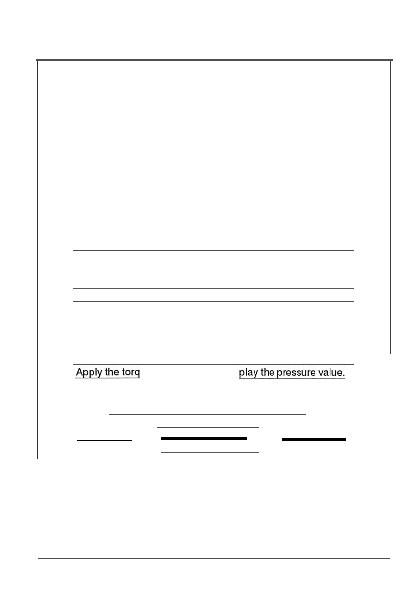
13) For quick measurement, follow the procedures
shown below :
Main procedures :
Connect the
II
Sensor Plu " to the meter's
Power on the meter & select the dis la unit.
II
again, the " Min
II
In ut Socket
11
11
•
II
Zero the meter b ush the
Zero Button
Connect the torque sensor cramp to the measuring
11
•
installation
ue force, meter will dis
Optional measuring procedures :
DATA HOLD
MEMORY RECORD
Max., Min.
8
RS232 OUTPU
Page 11

Power management :
I
AUTO POWER OFF
(Not activated during
Memory Record Selection)
5.
AUTO POWER DISABLE
I
or
I
MANUAL
POWER OFF
The instrument has built
II
-in
Auto Power Shut-off
II
in
order to prolong battery life. The meter will switch off
automatically
10 min.
if
none of the buttons are pressed within approx.
To disable this feature, Select the memory
record function during measurement, by pressing
the "
Max./Min.
6.
RS232 PC SERIAL INTERFACE
" button ( 3-4, Fig.
1).
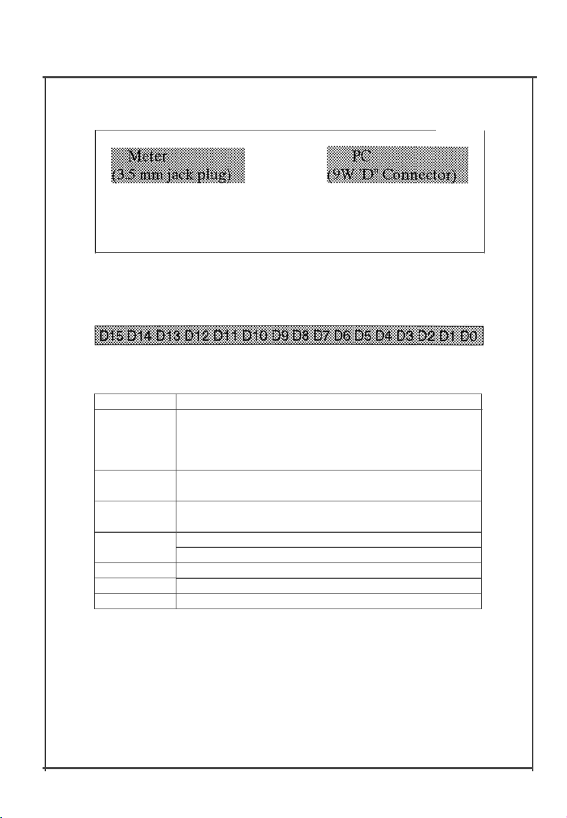
The instrument features an RS232 output via 3.5 mm
Terminal ( 3-13, Fig. 1).
The connector output is a 16 digit data stream which
can be utilized to the user's specific applica tion.
An RS232 lead with the following connection wi ll be required to link the instrument with the PC serial input.
9
Page 12
DO
End Word
D1 & D8
Display reading, D1 = LSD, D8 = MSD
00001234
D9
Decimal Point(DP), position from righ t to the left
0 = No DP, 1= 1 DP, 2 = 2 DP, 3 = 3 DP
D10
Polarity
0
= Positive
1 = Negative
D11 & D12
Annunciator for Display
Kq cm = 81
I LB inch = 82
I
N cm = 83
D13 1
D14
4
D15
Start Word
Center Pin ..................... ....................Pin 2
Ground/shield ...................................... Pin 5
The 16 digit data stream will be displayed in the
following format :
Each digit indicate the following status :
For example :
/f the display reading is 1234, then DB to 01 is :
RS232
FORMAT :
9600,
N, 8, 1
10
Page 13
RS-232 cable,
Model : UPCB-01
RS-232 cable, used for connecting
the torque meter & the computer.
Application
After setup whole hardware
LOTUS-123 .....
7.
BATTERY REPLACEMENT
1) When the left corner of LCD display show "
",
It is necessary to replace the battery. However, within
specification measurement may still be made for several
hours after low battery indicator ap pears before the
instrument become inaccurate.
2) Slide the Battery Cover ( 3-11, Fig. 1) away from the
instrument and remove the ba t tery.
3) Install a 9 V battery ( heavy duty ) an d rep lace the cover.
8.
OTHER OPTIONAL ACCESSOR IES
Software ( Window
version )
Torque meter + RS -232 cable
+ Computer + software
SW-U101-WlN
( SW-U101-W/N )
whole system can execute as a data
logger, data recorder.... record data
can be retrieved for EXCELL, ACCESS,
11
0007-TQ-8800
 Loading...