

Page 1

OPERATION MANUAL
PCE-PA 7500
POWER ANALYZER
Page 2

Table of Contents
Chapter 1 Overview .............................................................................................. 1
1.1 Profile ............................................................................................................1
1.2 Open packa g e inspect ion .....................................................................1
1.3 Use c on di ti on ............................................................................................. 2
1.3.1 Power connection ...............................................................................2
1.3.2 Fuse ...........................................................................................................2
1.3.3
1.3.4
E
nvironment .............................................................................................2
Prehea t
.................................................................................................... 2
1.4 Instrument and other characteristics ................................................... 2
Chapter 2 The front/rear Panel description and entry operation .............3
2.1 Front panel description ............................................................................ 3
2.2 Re ar panel description ............................................................................ 3
Chapter 3 Basic Operation Instructions ...........................................................4
3.1
Tur n on
........................................................................................................ 4
3.2 Display area de f i ni t io n .......................................................................4
3.3 Display interface switch........................................................................... 6
3.3.1 Measur e di splay button DISP ........................................................ 6
3.3.2 Measurement settings button SETUP .......................................... 6
Chapter 4 System Settings ......................................................................................7
4.1 Electric energy automatically returns to zero settings .................7
4.2 System language setting ........................................................................ 7
4.3 Key sound...................................................................................................... 8
4.4 Power upper Limit ................................................................................... 8
4.5 Current upper Limit .................................................................................8
4.6 Beep alarm switch ................................................................................... 9
Chapter 5 Wiring method ........................................................................................ 10
Chapter 6 Basic Principles and Technical Index ...........................................10
6.1 Basic principles........................................................................10
6.1.1 Measurement parameters and symbols.. . .......... . ............ ...11
6.1.2
Calc u lat i on form ula .. . ..... . ..... . ..... . . ..... . ..... . ..... . ..... . . ..... . ..
11
6.2 Ins t rumen t param e ter .. ..... . ..... . . ..... . ..... . . ..... . ..... . . ..... .. ....1 3
Page 3

1
Chapter 1 Overview
Thank you for purchasing and using our company's products. Before you use this
instrument, please confirm the final "complete set and warranty" chapter of the
manual. If there is an incompatible situation, please contact us as soon as possible
to protect your rights and interests.
1.1 Profile
PCE-PA 7500 digital power analyzer (digital power meter) uses high-speed 32-bit
processors and professional DSP digital signal processors. It has fast speed, frequency
bandwidth, full function, compact structure, stable testing, simple operation and
good human-machine interface, etc. It is a new generation of digital power analyzers.
The main parameters that can be measured are: voltage current validity value, voltage
current AC component, voltage current DC component,active power,reactive
power,apparent power, electric energy timing, power factor, Frequency, voltage current
peak value factor, voltage current peak value, etc. According to the different instrument
models, some instruments do not have harmonic analysis functions.
PCE-PA 7500 two channel power analyzer, It covers the advantages of a larger input
bandwidth (10 ~ 100Hz). At the same time, the Handler interface, RS232C/ RS485
interface, and USBTMC and USBCDC interfaces of the instrument. It provides conditions
for the instrument for the automatic sorting system and the remote operation of the
computer; The main difference between different models is the measurement range of the
current and the function of whether it has a harmonious analysis. The maximum test
current is 20A and the measurement accuracy is stable.
The main characteristics of the instrument:
4.3 -inch LCD display;
Soft power switch;
Chinese and English optional operation interface;
Input frequency range (10 ~ 100Hz);
The range automatically/manual control;
The maximum test current is 20A (related to the model), and the minimum current can
reach 0.001A
Provide a 5kHz line filter switch;
Flexible energy integration control;
Parameter comparison and Handle controllable output function;
Parameter gear select function;
Harmony analysis function (related to specific models);
Wave shape display function;
Support U disk file storage, the instrument program can be upgraded through the U disk;
Serial interface: RS-232C provides great convenience for the serial communication of
the instrument and peripheral device. The peripherals can set the functions and
parameters of the instrument through the interface, which can basically replace the
function of the panel keyboard.
1.2 Open package inspection
After the package is opened, you should check whether the instrument appearance is damaged
due to the transportation. We do not recommend that you call the instrument when the
appearance is damaged.
Page 4

2
The front panel of the instrument is marked with the specific model and the main measurement
scope of the instrument. Check whether the model you ordered is consistent. Please confirm it
according to the packing list.
Instrument models and basic functions in Table 1-1:
Note: It is best to keep the packaging box properly after opening the box,
to avoid the instrument causing unnecessary damage due to the unsuitable packaging box in
the future transportation.
1.3 Use condition
1.3.1 Power connection
Power voltage: 100 ~ 240 VAC
Power frequency: 45 ~ 440Hz
Power supply power range: not less than 30 VA.
The power supply input live wire L, Neutral wire N, Earth E should be the same as the
power plug in this instrument.
This instrument has been carefully designed to reduce the wave interference caused by the
input of the AC power supply end. However, it should still be used as much as possible in a
low noise environment. If it cannot be avoided, please install the power filter.
Warning: In order to prevent leakage from causing damage to instruments or human, users
must ensure that the ground wire of the power supply is earthing reliably.
1.3.2 Fuse
In the package, there is a fuse, the user should use the fuse of which offered by the factory.
1.3.3 Environment
Normal working temperature:0℃~40℃, Humidity: 20~80% RH
Reference work temperature: 20℃±8℃, Humidity: < 80% RH
Transportation environment temperature: 0℃~55℃, Humidity:93% RH
Please do not use it under dust, vibration, direct sunlight or corrosive gases.
In order to ensure good ventilation in this test instrument, do not block the left wind
holes to maintain accuracy of this instrument.
This instrument has been carefully designed to red uce the wave interfe rence
caused by the input of the AC power supply side. However, it should still be used
as much as possible in a low noise environment. If it ca nnot be avoided, please
install the po wer filter.
If the instrument is not used for a long time, ple ase place it in the ventilation room
with a temperature of 5 ° C ~ 40 ° C in the original packaging box or similar box,
and the relative humidity is less than 85% RH and avoid dire ct sunlight.
1.3.4 Pr eheat
In order to ensure the precise measurement of the instrument, the preheating time
should be not less than 30 minutes.
Do not switch the instrument frequently to avoid causing internal data confusion.
1.4 Instrument and other characteristics
Power consumption:about 16 VA
Shelf size(W*H* D): 215mm * 88mm * 335mm
Dimension(W*H* D): 235mm * 105mm * 360mm
Weight:about 3.0kg
Page 5
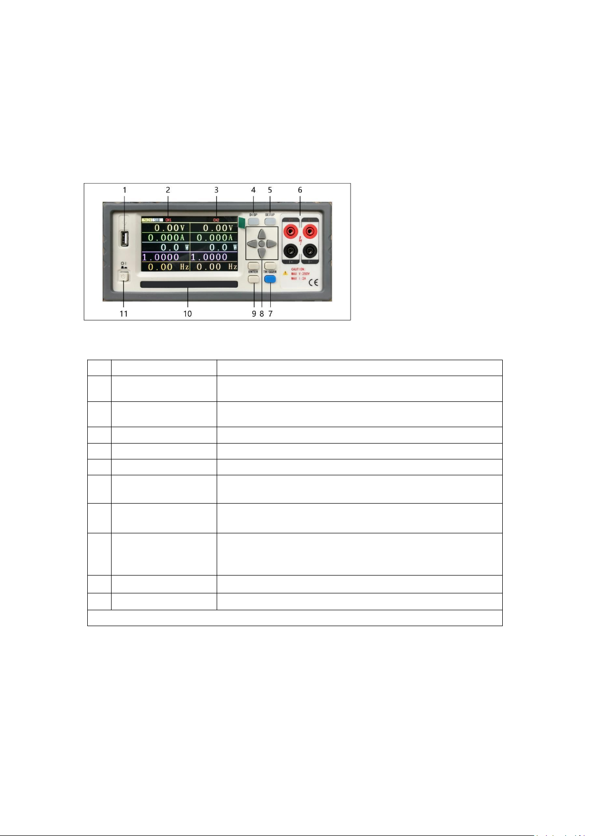
3
Chapter 2 The front and rear panel description and basic operation
1
USB HOST
USB Host interface is used for U disk storage and upgrade.
2
Ch1
Display the Ch1 electrical parameter, and switch the
main/sub -parameter through the left and right keys.
3
Ch2
Display the Ch2 electrical parameter, and switch the
main/sub -parameter through the left and right keys.
4
DISP
Switch from the setting interface to the display interface.
5
SETUP
Switch from the display interface to the setting interface.
6
Ch1 front wiring port
Ch1 front wiring port, Maximum support 2A current
7
Clear zero
Cumulative electricity
Press this key to clear zero the cumulative electricity of
sub-parameters.
8
Universal direction
keys (CURSOR)
Universal direction keys (CURSOR) Four direction buttons
and confirmation keys up, down, left and right.
9
ENTER
After the direction key moves the cursor position, the soft
key area corresponds to different functions. Press to modify
the corresponding parameter value.
10
Model bar
Shows device model, brand information
11
POWER
Power switch
Figure 2-1 front panel description
This chapter describes the basic operation steps of the PA7500 instrument. Before
using the PA7500 instrument, please read the content of this chapter in detail so
that you can quickly be familiar with the operation of the PA7500 instrument.
2.1 Front panel description
Figure 2-1 briefly explained the front panel of PCE-PA 7500
2.2 Rear panel description
Figure 2-2 briefly description on the rear panel of the PCE-PA 7500
Page 6
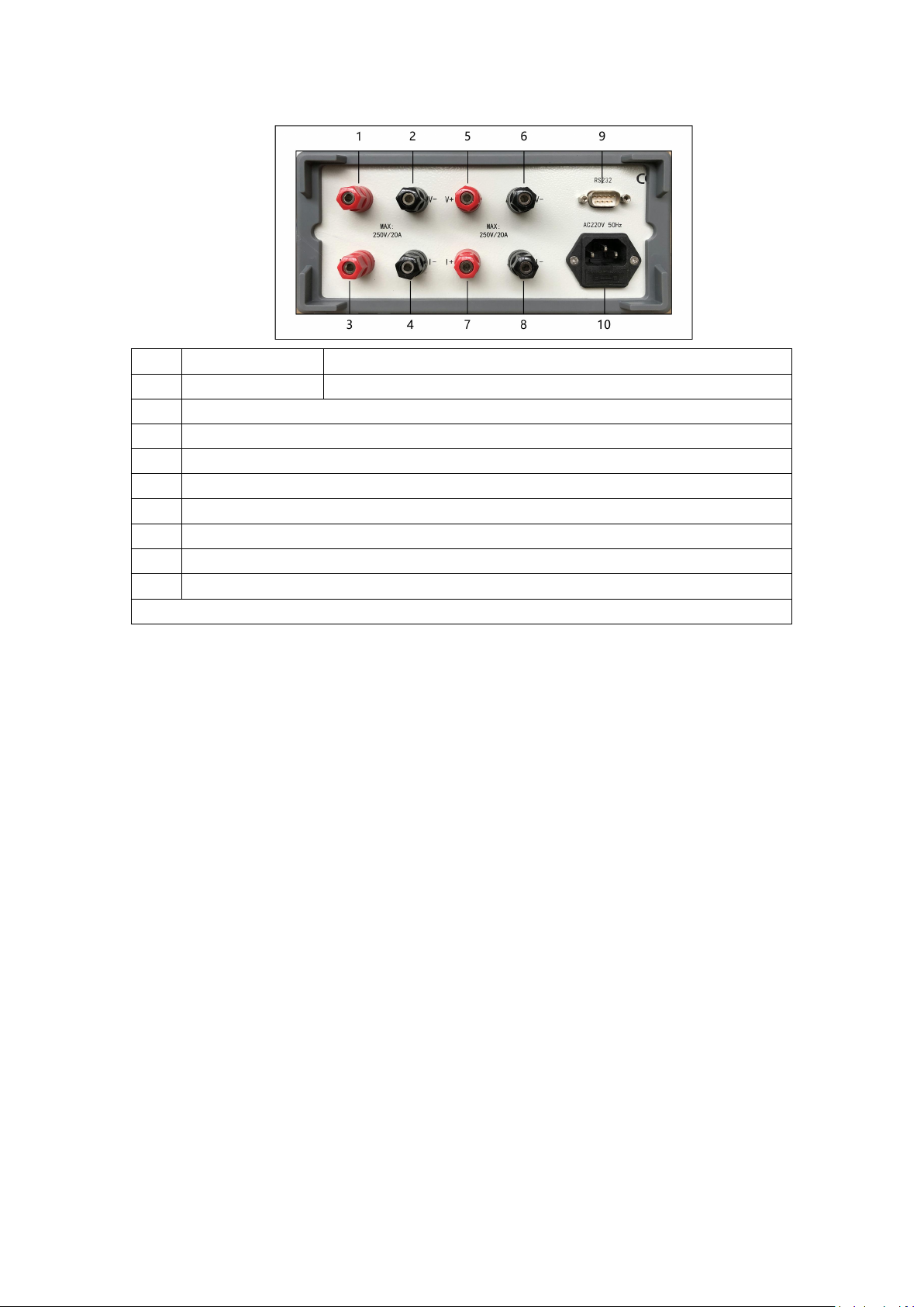
4
10
Power socket
Input AC power
9
RS232C por t
Serial communication with the computer (optional)
8
Channel 1 Load Negative (N)
7
Channel 1 Load Positive (L)
6
Channel 1 Voltage Negative (N)
5
Channel 1 Voltage Positive (L)
4
Channel 2 Load Negative (N)
3
Channel 2 Load Positive (L)
2
Channel 2 Voltage Negative (N)
1
Channel 2 Voltage Positive (L)
Figure 2-2 rear panel description
Chapter 3 Basic Operation Instructions
Basic operation description of the PCE-PA 7500 buttons:
1) Use menu buttons (DISP, SETUP) and soft keys to select the page you want to display.
2) Use direction keys (←, ↑, →, ↓) to move the cursor to the parameter area that can be set,
and the corresponding area will become a cursor color (blue)
3) The soft key function corresponding to the parameter of the current cursor area will be
displayed in the "soft key area". The corresponding operation is performed by the soft key
under the LCD or you can press the ENTER key to quickly circulate the enumeration status
of the selected parameter.
3.1 Turn on the device
Plug in a 3 wire power cable to ensure the reliable connection of the power supply
Ground. Press the power switch in the lower left corner of the instrument front panel,
the instrument is turned on, displaying the display screen.
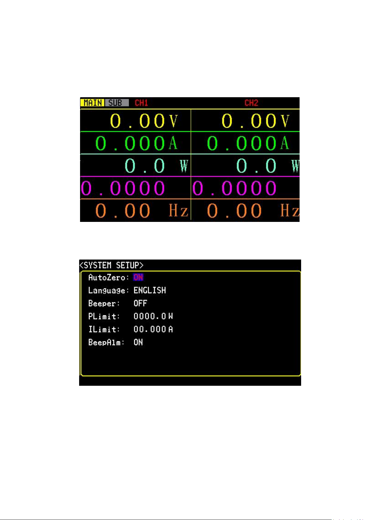
Figure 3-1 shows the display screen of PCE-PA 7500
3.2 Display area definition
PCE-PA 7500 uses 24 -bit color 4.3 -inch color LCD screen with a resolution of 480 ×
272. The content of the screen display is divided into the following display area,
Page 7

5
3-1:Main parameter display screen
1
Channel 1 parameter
This column shows the parameter of Channel 1
2
Channel 2 parameter
This column shows the parameter of Channel 2
3
Voltage value
This row shows the voltage value of each channel
4
Current value
This row shows the current value of each channel
5
Active power
This row shows the active power value or each channel
(voltage value* current value*power factor)
6
Power factor
This row shows the power factor of each channel
7
Frequency
This row shows the input voltage frequency of each
channel
8
Cumulative
electricity
This row shows the cumulative electricity of each channel
9
Apparent power
This row shows the apparent power value of each channel
(voltage value*current value)
10
Reactive power
This row shows the reactive power value of each channel
(apparent power-active value)
Table 3- 1
th e d e sc ri p ti o n o f each area
3-2:Sub-parameter display screen
The meaning of each area is shown in Table 3-1
Page 8
6
3.3 Display interface switch
The DISP button and the Setup button are the most frequent two buttons in the page
switching process, which are entrances to the test related page and setting related pages.
3.3.1 Measurement display button DISP
Press DISP button, enter the measure m e n t display homepage
3.3.2 Measurement setting button SETUP
Press SETUP button, enter the system setting homepage
Page 9
7
Chapter 4 System settings
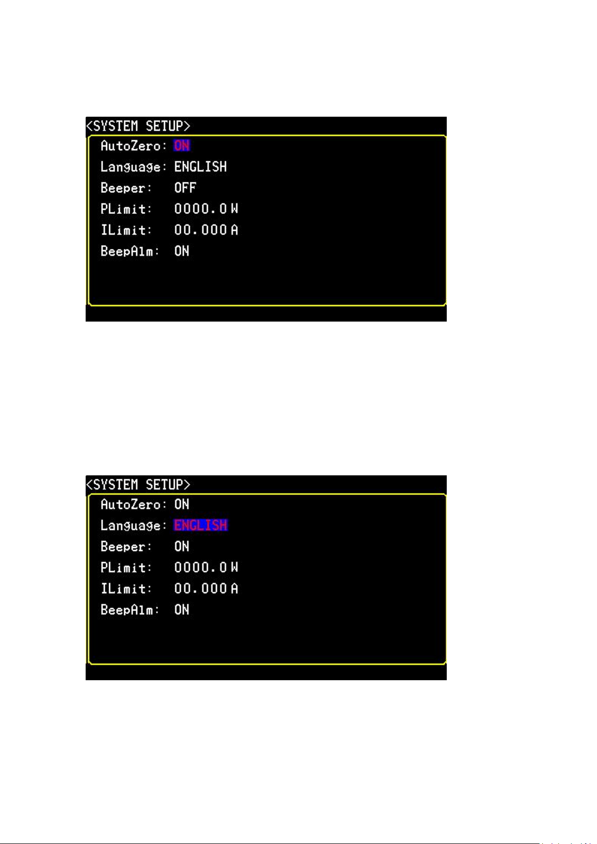
Press SETUP key into the system settings interface
4.1 Electric energy automatically returns to zero settings:
The instrument can set the electric energy automatically to zero, set ON or OFF, the
user can set it according to their own needs, the sett ing steps are as follows:
Use the cursor key to move the cursor to the AutoZ ero area, press the [ENTER] key,
and then press the upper and lower keys to select, "ON " and "OFF" two options. After
selecting, press [ENTER] to complete the settings. When the electric energy
AutoZero is ON, the total of the previous electric energy is cleared to zero when each
turning on the device. When the electric energy AutoZero is OFF, it will not clear the
last cumulative electric energy when turning on the device. No matter what settings
are settled, the cumulative electric energy can be cleared on the test interface
through the blue TRIGGER key.
4.2 System language setting:
Set up system language and provide two system language choices: Chinese/English.
The setting steps are as follows:
Use the cursor key to move the cursor to the language area, press the [ENTER] key,
and then press the upper and lower keys to select. After selecting, press the [ENTER]
key to complete the settings.
Page 10
8
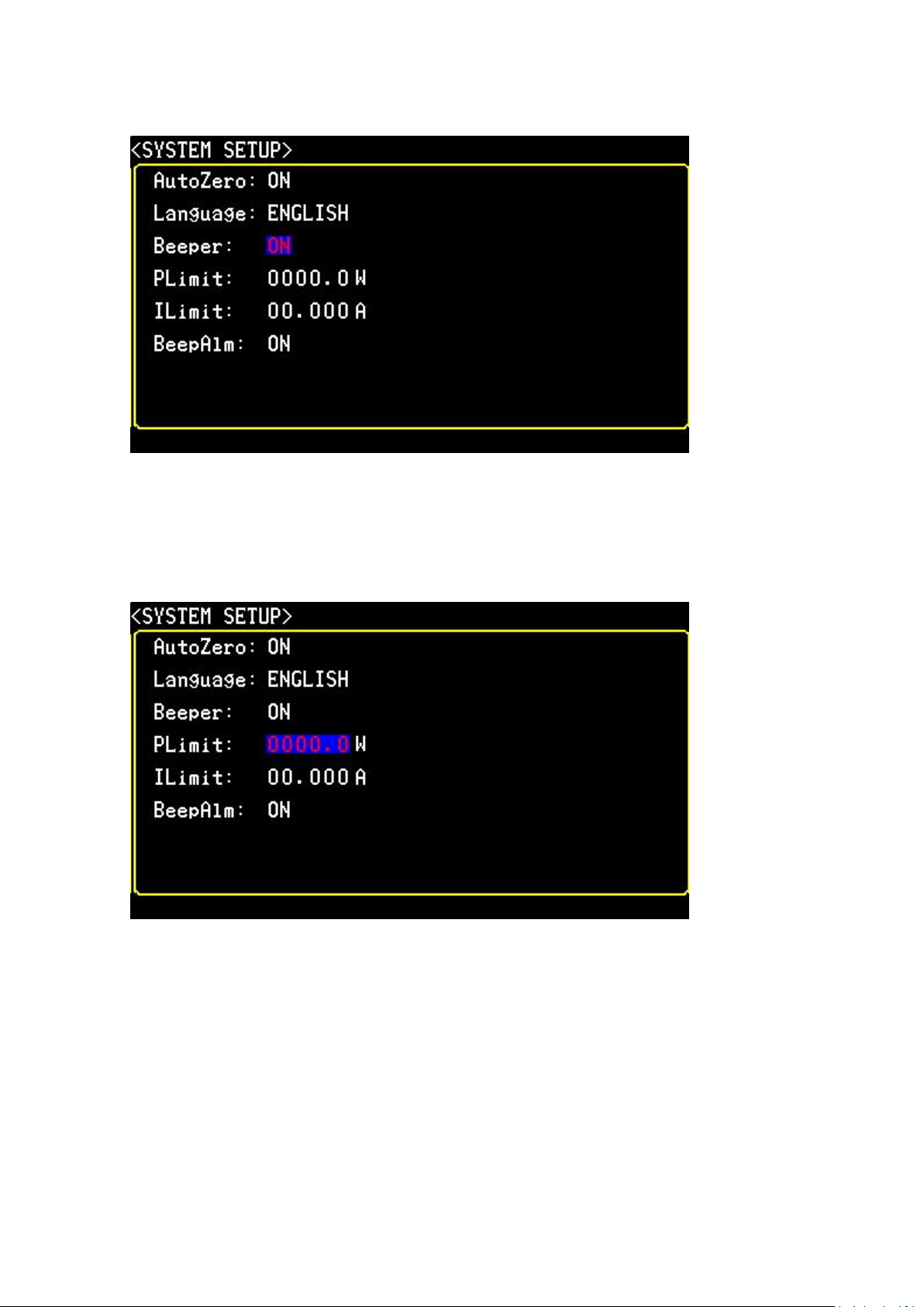
4.3 Key sound:
ON or OFF the key sound. The setting steps are as follows:
Use the cursor key to move the cursor to the Beeper area, press the [ENTER] key,
and then press the upper and lower keys to select. After selecting, press the [ENTER]
key to complete the settings.
4.4 Power upper Limit
Set the power upper limit,It will alarm if exceed this setting value. The setting range
is 0000.0 ~ 9999.9W.
The setting steps are as follows:
Use the cursor key to move the cursor to the PLimit area, press the [ENTER] key,
and then press the upper and lower keys to select the value, ↑add value,↓ reduce the
value, ←move the setting number to the left, →and move the setting number to the
right. After setting, press the [ENTER] key to complete the setting.
4.5 Current upper limit
Page 11
9
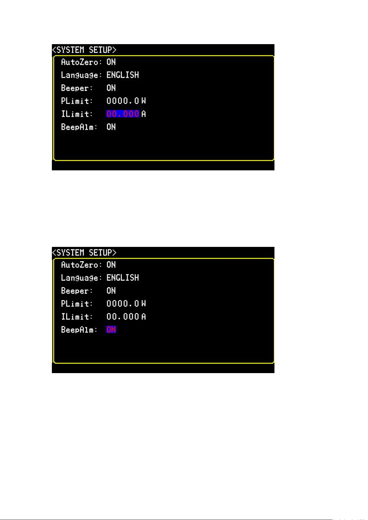
Set up the current limit, It will alarm if exceed this setting value. The setting range is
00.000 ~ 20.000A. The setting steps are as follows:
Use the cursor key to move the cursor to ILimit area, press the [ENTER] key, and
then press the upper and lower keys to select the value, ↑add value,↓ reduce the
value, ←move the setting number to the left, →and move the setting number to the
right. After setting, press the [ENTER] key to complete the setting.
4.6 Beep alarm switch
When the option is ON, it will alarm when the power/current exceeds the setting
value. The setting steps are as follows:
Use the cursor key to move the cursor to the BeepAlm area, press the [ENTER] key,
and then press the upper and lower keys to select. After selecting, press the [ENTER]
key to complete the settings
Page 12
10
Chapter 5 Wiring method
PCE-PA7500
POWER
ANALYZER
485
USB
Computer
Handle control
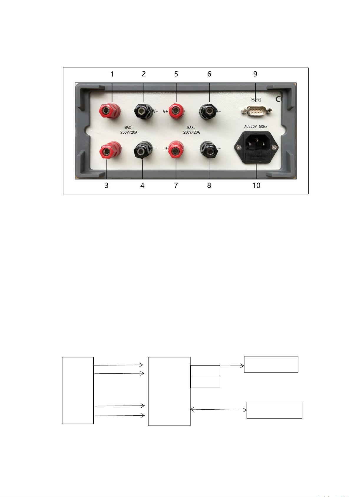
PCE-PA 7500 instrument provides four test wiring input terminals, namely voltage high-end,
voltage low-end, load high-end, load low-end.
As shown in the above figure: connect the channel 1 voltage input into the terminal 5-6 (pay
attention to distinguish L/N), connect the channel 1 load to the terminal 7-8 (pay attention to
distinction L/N), then Channel 1 wire connection is finished.
As shown in the above figure: connect the channel 2 voltage input into the terminal 1-2 (pay
attention to distinguish L/N), connect the channel 2 load to the terminal 3-4 (pay attention to
distinction L/N), then Channel 2 wire connection is finished.
Chapter 6 Basic Principles and Technical Index
6.1 Basic principles
The system principle and principle diagram, as shown in Figure 6-1:
Voltage RS232
Differences
Unit
Under
Test
Current
Differences
(Figure 6 - 1 Sy s t e m struc t u re )
Page 13
11
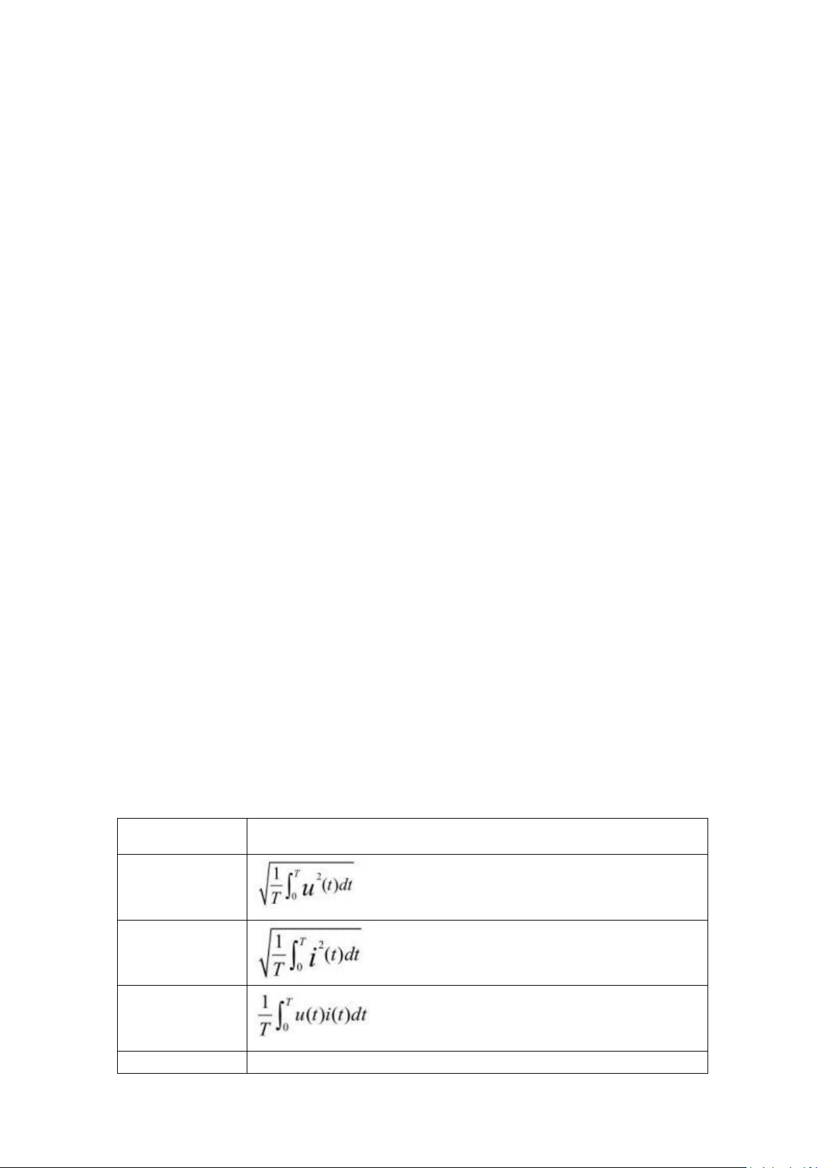
The main structure of PCE-PA 7500 two channel single -phase power analyzer is to
Measurement
parameter
Calculation formula/calculation method
URMS
IRMS
P
VA
URMS * I RMS
input the UUT system to the Power Analyzer through the voltage and current of the Power
Analyzer by Difference input. Through the amplification, filtering, sampling, and AD
conversion inside the instrument, the simulation signal of the upcoming voltage and
current is converted into a digital amount Ui and Ii. Then the CPU obtain the parameters
such as the voltage validity value, current validity value, active power and power factors
through the discrete integral with following formulas, then send this parameters to LCD
display.
Because the calculation of the effective value contains AC components and DC components,
AC wave forms may become non -standard wave forms due to partial distortion. So here the
value calculations are real effective values, that is, TRMS.
The calculation power also contains the AC and DC components of the voltage current, so
the power calculation is the average power, and it is also the real power value, that is, the
active power. The positive and negative sign of power represents the direction of power
(respectively represents the energy provided by the power supply to the load, or the energy
provided by the load to the power supply).
The power factor is the ratio of power (total power) in power (total power). In theoretically,
the power factor is not divided into positive and negative signals. Between ~+1, it is exactly
the leading current of voltage, and the negative sign represents the voltage backward
current.
The power factor is the ratio of the active power and apparent power (total power).
Theoretically, power factor is no positive and negative numbers,
However, in the application of the power meter, the phase relationship of the voltage
current is judged by positive and negative numbers. Value between -1 and +1, positive
value represents voltage lead current, negative value represents the voltage backward
current.
6.1.1 Measurement parameters and symbols
Freq:Input source frequency
PF:Power factor
P:Active power
VA:Apparent power
VAR:Virtual power
E:Electric energy
6.1.2 Calculation formula
Page 14
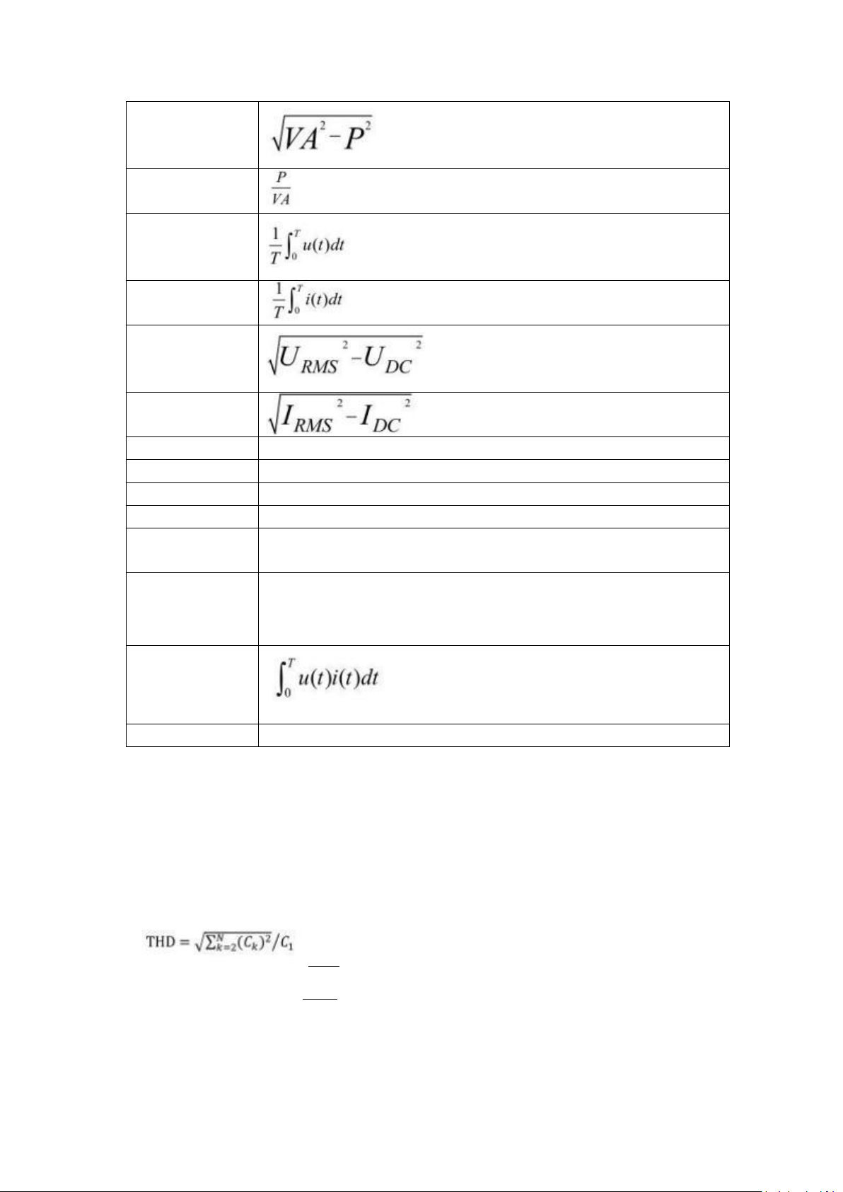
12
VAR
PF
UDC
IDC
UAC
I AC
UPK+
The maximum value of u(t) during a sampling cycle
UPK-
The minimum value of u(t) during a sampling cycle
I PK+
The maximum value of i(t) during a sampling cycle
I PK-
The minimum value of i(t) during a sampling cycle
CFi
The ratio of the maximum sampling point absolute value and the
Current valid value during a sampling cycle
THDu/THD i
Calculation of total harmonics of voltage and current,
Provide two computing standards, namely IEC standards and
CSA standards. For details, please see the remarks under the
table.
Energy
the T here is the integration time set by the
user
Freq
Obtained at zero -point detection
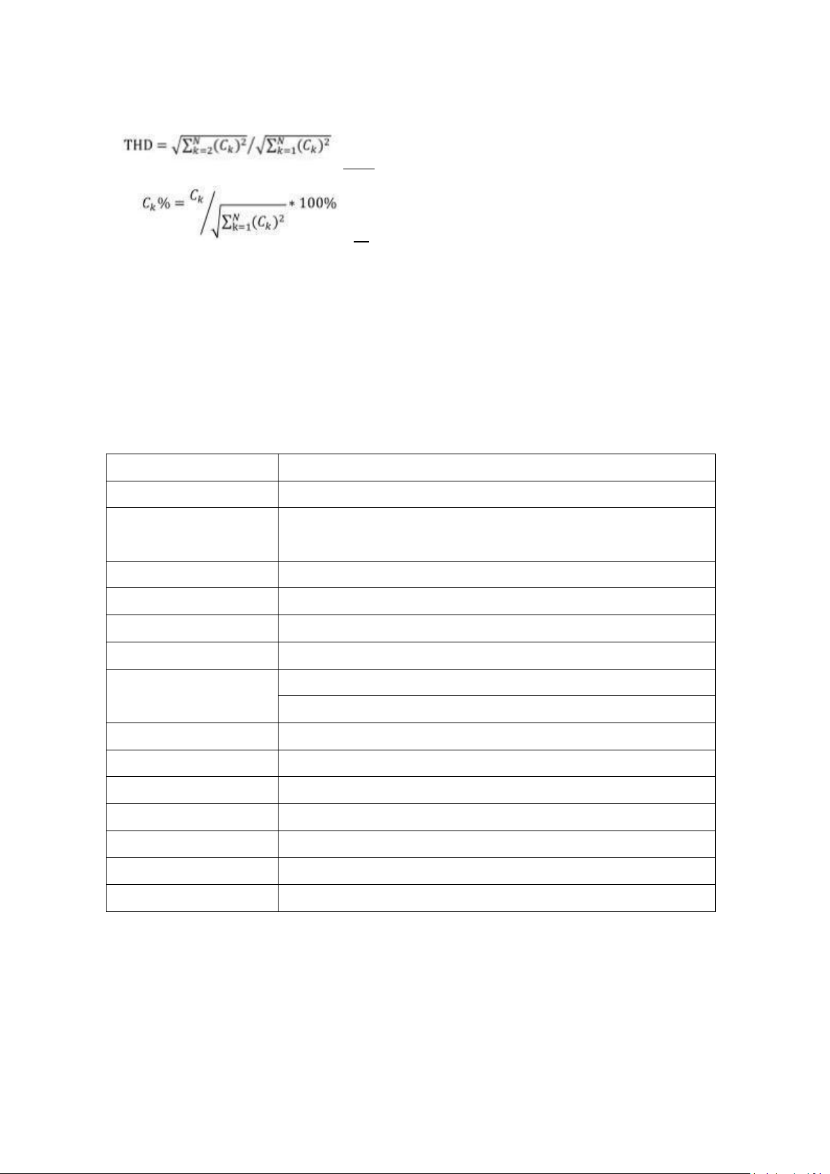
The total harmonic calculation is according to the International Electricity
Commission (IEC Standard) and the Canadian Standards Association (CSA
Standard), and two calculation methods (optional on the harmonic settings page)
are given accordingly. The introduction is as follows:
IEC Standard: Calculate the ratio (%) between the rms of 2 to 50 harmonics components
valid value and fundamental harmonic valid value.
The calculation formula is as follows:
Total harmonic calculation
%
CSA Standard: Calculate the ratio(%) between the rms of 2 to 50 harmonics component
valid value and the rms of 1 to 50 harmonics component valid value.
The calculation formula is as follows
K harmonics percentage component calculation
Page 15
13
6.2 In str u me n t para met er
Wi rin g me th o d
Si n gl e ph a se
Di s pl a y
LC D
Me as u re me nt ite m
Vo lta ge V, Cu r r en t A , A c ti v e P ow er W,
Po we r Fa ct or P F, Fr e q u en cy Hz
Me as u re me nt mo de
Tr m s
Vo lta ge ra ng e
2V ~3 0 0 V AC (R an ge au to ma t ic sw it c h)
Cu r re nt ra n g e
0.0 01 A~ 20 A AC (R an g e a u to ma tic sw it c h )
Po we r ra ng e
0.1 W ~ 6 k W
Po we r Fa ct or
ra n ge
0.0 01 ~1 .0 0 0
Ca l cu la t io n: Wa tt (W )
÷[ Voltage(V)* Current (A)]=PF
Fr e qu en cy r a n g e
10 ~ 10 0H z
Ba sic ac cu ra c y
±(0.4% reading+ 0.1 range)
Me as u re me nt sp ee d
0.1 s, 0. 2 5s , 0. 5s , 1s , 2s , 5s
Input impedance
2KΩ/V
Power supply
100~240V AC 45-440Hz, 100-300V DC
Communication port
Standard RS232 or RS485, Relay output function optional
Accessories
Power cable, warranty card, manual, communication cable
Total harmonic calculation
k harmonics percentage component calculation
Explanation of the character meaning used in the two formulas above:
C 1: The valid value of the fundamental harmonic (that is, the one -time harmonic) of U
(voltage) or I (current);
C k: The valid value of the K harmonics of U (voltage) or I (current);
k: Harmonic times index, 2 ~ 50
N: The maximum harmonic coefficient, that is, 50.
C k %: The percentage component calculation results of voltage or current K harmonics.
Page 16
7 Disposal
For the disposal of batteries in the EU, the 2006/66/EC directive of the European
Parliament applies. Due to the contained pollutants, batteries must not be disposed of as
household waste. They must be given to collection points designed for that purpose.
In order to comply with the EU directive 2012/19/EU we take our devices back. We either reuse them or give them to a recycling company which disposes of the devices in line with law.
For countries outside the EU, batteries and devices should be disposed of in accordance
with your local waste regulations.
If you have any questions, please contact PCE Instruments.
8 PCE Instruments contact information
Germany
PCE Deutschland GmbH
Im Langel 26
D-59872 Meschede
Deutschland
Tel.: +49 (0) 2903 976 99 0
Fax: +49 (0) 2903 976 99 29
[email protected]
www.pce-instruments.com/deutsch
United Kingdom
PCE Instruments UK Ltd
Trafford House
Chester Rd, Old Trafford
Manchester M32 0RS
United Kingdom
Tel: +44 (0) 161 464902 0
Fax: +44 (0) 161 464902 9
[email protected]
www.pce-instruments.com/english
The Netherlands
PCE Brookhuis B.V.
Institutenweg 15
7521 PH Enschede
Nederland
Telefoon: +31 (0)53 737 01 92
[email protected]
www.pce-instruments.com/dutch
France
PCE Instruments France EURL
23, rue de Strasbourg
67250 Soultz-Sous-Forets
France
Téléphone: +33 (0) 972 3537 17
Numéro de fax: +33 (0) 972 3537 18
[email protected]
www.pce-instruments.com/french
Italy
PCE Italia s.r.l.
Via Pesciatina 878 / B-Interno 6
55010 Loc. Gragnano
Capannori (Lucca)
Italia
Telefono: +39 0583 975 114
Fax: +39 0583 974 824
[email protected]
www.pce-instruments.com/italiano
United States of America
PCE Americas Inc.
1201 Jupiter Park Drive, Suite 8
Jupiter / Palm Beach
33458 FL
USA
Tel: +1 (561) 320-9162
Fax: +1 (561) 320-9176
[email protected]
www.pce-instruments.com/us
Spain
PCE Ibérica S.L.
Calle Mula, 8
02500 Tobarra (Albacete)
España
Tel. : +34 967 543 548
Fax: +34 967 543 542
[email protected]
www.pce-instruments.com/espanol
Turkey
PCE Teknik Cihazları Ltd.Şti.
Halkalı Merkez Mah.
Pehlivan Sok. No.6/C
34303 Küçükçekmece - İstanbul
Türkiye
Tel: 0212 471 11 47
Faks: 0212 705 53 93
[email protected]
www.pce-instruments.com/turkish
Denmark
PCE Instruments Denmark ApS
Birk Centerpark 40
7400 Herning
Denmark
Tel.: +45 70 30 53 08
[email protected]
www.pce-instruments.com/dansk
 Loading...