

Page 1
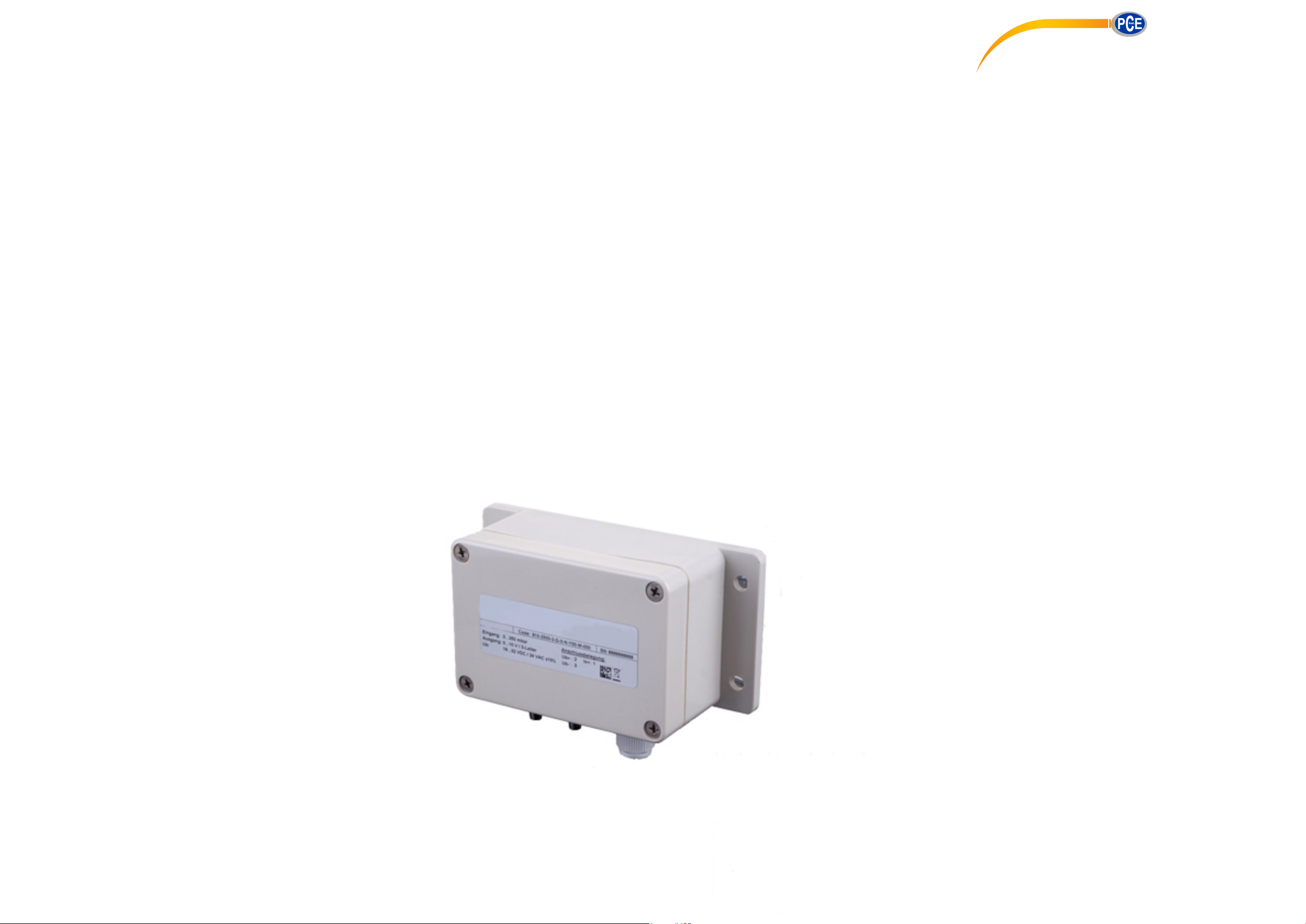
Differential Pressure Transmitter
PCE-DDMU 10
INSTRUCTION MANUAL
PCE Americas Inc.
711 Commerce Way
Suite 8
Jupiter
FL-33458
USA
From outside US: +1
Tel: (561) 320-9162
Fax: (561) 320-9176
[email protected]
www.pce-instruments.com/english
www.pce-instruments.com
PCE Instruments UK Ltd.
Unit 11
Southpoint Business Park
Ensign way
Hampshire / Southampton
United Kingdom, SO31 4RF
From outside UK: +44
Tel: (0) 2380 98703 0
Fax: (0) 2380 98703 9
Page 2

Table of contents
1. General information
2. Product identification
3. Installation
4. Initial start-up
5. Operation
6. Dimensions / Fixing
7. Maintenance
8. Return
9. Warranty conditions
Operating Manual
Differential Pressure Transmitter PCE-DDMU 10
Page 3
1 General information
Do not blow into the pressure ports!
This causes damage to the de vice .
- This operating man ual contains important information on the pr oper usage of the device. Read this
operating manual carefully before installing and
starting up the pressure measuring device.
- Adhere to the safety notes and operating instructions which are gi v en in the operatin g m anual . Ad ditionally applicable regulations regarding occupational safety, accid ent prevention as we ll as na tion al
installation standards and engineering rules must
be complied with!
- This operating ma nual is part of the d evice. It must
be kept near its locati on and always be accessible
to all employees.
- This operating m anual is copyright ed. The c ontents
of this operating manu al refl ect th e vers i on available
at the time of printing.
WARNING! To avoi d operator hazards and d amage to the devic e, the following i nstructions may
only be carried out by qualifie d technical personnel.
Limitation of liability: In case of nonobservance of the ope rating manual, inappropriate use, modifications or damage, no liability is
assumed and warrant y claim s will be e xcl ud ed.
Symbols used:
: Warning
! : Caution
: Note
– Technical modifications reserved –
2 Product identi fi cation
2.1 Intended use
-
The PCE-DDMU 10 differential pressure
transmitter has been developed for the
measurement of pressure difference of dry, nonaggressive gases and pressurized air and can be
used for a wide range of different HVAC
applications.
Its robust design means it can be used in the
laboratory and under industrial conditions.
Preferred areas of use are in heating, ventilation
and air conditioning systems; clean room and
medical technology, filter technology and draft
metering checks.
It is the operator's responsibility to check and verify
the suitability of the device for the intended application. If any doubts remain, please contact our sales
department in order to ensure proper use.
PCE Instruments is not liable for any incorrect
selections and their effects!
WARNING! – Danger by inappropriate use!
2 Ide
2.
ntification
- The device can be identified by its manufacturing
label. It provides the most important data. The
product can be clearly identified by the ordering
code.
Nominal
pressure
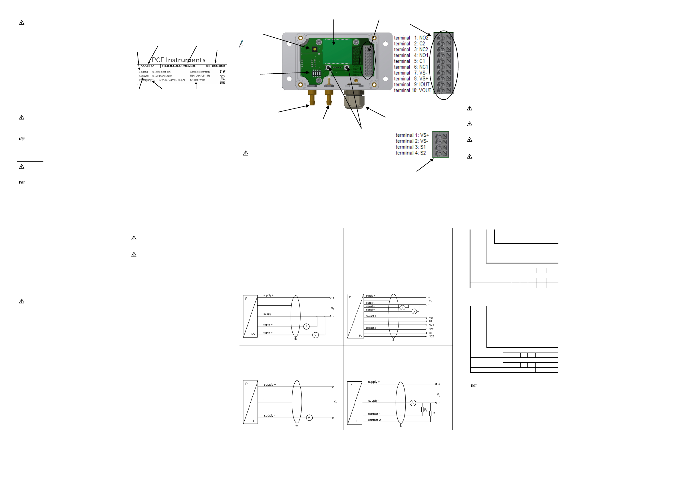
Fig. 1: Manufacturing label
range
Signal
Type designation
Supply
Ordering code
Connector pinout
Serial
number
! The manufacturing label may not be removed
from the device!
2.3 Package contents
Please verify that all listed parts are included in the
delivery undamaged and comply with your order:
1 Differential Pressure Transmitter PCE-DDMU 10
1 Operating manual
2.4 Transport and storage
Permissible temp erature for storage: -10 °C to + 70 °C
For transport make sure that both pressure inputs of
differential pressu re sensors are open. The air trans port
of absolute pressur e sensors should onl y be done in a
pressure compensated cabin.
2.5 Declaration of conformity / CE
The delivered device fulfills all legal requirements.
The applicable directives, harmonised standards and
documents
The
CE sign on the manufacturing label.
are listed in the EC declaration of conformity.
operational safety is
additionally confirmed by the
3 Installation
3.1 Mounting and safety instructions
WARNING! This d evice may only be installed by
qualified technical personnel who have read and
understood the operating manual!
WARNING! Install the device only when depressurized and current-free!
! Handle this device wit h car e, both in packaged and
unpackaged condition!
! No modifications/ changes should be made on the
device.
! Do not throw the device!
! Do not use any f orce when i nstall ing the d evice , to
prevent damage of the device and the plant!
! Avoid sources of interference (transformers,
transmitters, mot ors etc.) or sources of heat in the
surrounding area.
! Shocks or vibrations at the mounting connection
can cause distortions to the output signals.
3.2 Installation steps
- Carefully remove the pressure measuring device
from its p ackage and dispose of the pack age properly.
- Mount the devic e in a suitable location usi ng both
straps. The corres ponding dime nsions are provided
under "6".
- Connections should be vertical, i. e. the pressure
connections shoul d point downwards. The sensors
are calibrated in t he fac tor y for th ese m ounti ng conditions. In addit ion, t he fo rmati on of co ndensa tion in
the pressure tubing of the sensor is also reduced.
- Use the appropriate hoses for the connection.
Display
(optional)
Potentiometer for adjusting damping
Phillips-screwdriver
size 2
Configuration
switching
Negative
pressure connection
Positive
pressure connection
Fig. 2: PCE-DDMU 10
3.3 Electrical installation
WARNING! This d evice may only be installed by
qualified technical personnel who have read and
understood the operating manual!
- Open the top cover and establish the electrical
connection of the device according to the following description. Screw the top cover onto the bo x
again.
- Guide externally the power supply line through
the right cable fitting so that the wires can be
connected with the right terminal block (SUPPLY) without any problem.
- Next, tighten the cable gland by hand. Make
sure, however, that the cable is strain-relieved.
3-wire-system (current / voltage) 3-wire-system (current / voltage)
supply -: terminal 7: VSsupply +: terminal 8: VS+
signal: terminal 9: IOUT
signal: terminal 10: VOUT
2-wire-system (current) 2-wire-system (current) with two outputs
supply +: terminal 1: VS+
supply -: terminal 2: VS-
Menu button
3.4 Pressure port
- Connect the hose with the higher pressure to the
right hand (positive) pressure port.
- Connect the hose with the lower press ure to the
left hand (negative) pressure port.
Output 2 NO2: terminal 1: NO2
Output 2 C2: terminal 2: C2
Output 2 NC2 terminal 3: NC2
Output 1 NO1 terminal 4: NO1
Output 1 C1 terminal 5: C1
Output 1 NC1 terminal 6: NC1
supply -: terminal 7: VSsupply +: terminal 8: VS+
signal: terminal 9: IOUT
signal: terminal 10: VOUT
supply +: terminal 1: VS+
supply -: terminal 2: VSoutput 1: terminal 3: S1
output 2: terminal 4: S2
terminal block
3 wire system
Cable gland M16x1.5
terminal block
2-wire-system
with two outputs
4 Initial start-up
After switching on the power supply, the output
signal can be measured. Variations in the output
signals may have two possible causes:
1. The warm-up time of the sensor is about 30min.
After this period, the sensor signal should be
stable for zero differential pressure and constant
ambient temperature.
2. For small pressure ranges, a slight deviation in
the zero point due to ambient conditions can occur. This error can be corrected by adjusti ng the
zero-point potentiom eter of the sensor after the
warm-up tim e. (Set the output signal of the sensor with both pressure inputs open to the nominal value.)
5 Operation
5.1 General information
WARNING! Before st art-up, the user must check
to ensure proper instal lati on an d for an y visible d efects.
WARNING! T he device may only be started and
operated by authori zed personnel who have read
and understood the operating manual!
WARNING! T he device may only be used within
the technical specifications (see the data in the
data sheet)!
WARNING! Do not touch the bonding wires – this
can destroy the device.
5.2 Setting of damping
Potentiometer for setting the damping is located
adjacent to the displ ay on the left (see image 2).
The damping of the device c an be set by turning a
size 2 Phillips screwdriver in the area of 0 to
5000ms.
5.3 Menu buttons
Zeroing: push left menu button for at least 1 second
5.4 Configuration switch
3-wire-system:
2 3 4
1
On Zero adjustm en t act ive at
Off Off 1,6 4 10 40 250 1000
On Off 1,0 2,5 6 25 60 400
Off On 160 600
2-wire-system:
1
2 3 4
On On Zero adjustm en t activ e at
Off Off 1,6 4 10 40 250 1000
On Off 1,0 2,5 6 25 60 400
Off On 160 600
The switches 1 an d 2 don't have an y function
at special pressure ranges.
Off 0 ... 10 V / 0 ... 20 mA
On 0 ... 5 V / 4 ... 20 mA
Off Automatic zero adjustm en t
off
start and for 24h
Nominal pressure rang e
Customized ranges
Off Off Autom atic zero adjustment
off
On Off Zero adjustment active at
start
Off On Zero adjustment active at
start and for 24h
start, then every 7 days
Nominal pressure rang e
Customized ranges
Page 4
5.5 Performance of disp lay
Switch o n
Activate the menu with the right key.
Menu
"CLEAR?" flashes in the lower line, in the upper li ne "no" is
displayed; you can select between "yes" and "no" with the ri ght hand key. Confirm the selection with the l eft
hand key.
Menu
"CLEAR?" flashes in the lower line, in the upper li ne "no" is
d "no" with the right hand key. Confirm the sel ection with the left
hand key.
Menu
MODE
Menu only activated with contacts
selected with the right hand key. Confirm the selection with the left hand key.
SP
Values for set points in %
played in the upper line; it is possible t o change the value with the right hand key. Confirm the selection with
the left hand key.
RP
Values for reset points in %
"SP %" flashes in the lower line, the current val ue is
displayed in the upper line; it is possible to change the value with the right hand key. Confirm the selection with
the left hand key.
D. ON
Turn-on delay in s
D. OFF
Return switching delay in s
Menu
Setting the pressure unit
"unit" flashes in the lower line, the currently set unit is di splayed in
the upper line; the unit can be selected with the right hand key. Confirm the selection with the left hand key.
Menu
Span value for display can be set when the user unit is selected
"SPAN" now flashes in the lower line, the currently set value is displayed in the upper li ne; the position can be
n be changed with the right hand key, the
selection is confirmed with the left hand key.
Menu
Calibration of the Offset to the current value
"CAL. OFS?" flashes in the lower line, in the upper line "no"
hand key.
Menu
Calibration of the endpoint (display and analogue output) to the current pressure level.
"CAL. FSO?" flashes in the lower line, in the upper line
"no" is displayed; you can select between "yes" and "no" with the right hand key. Confirm the selection with the
left hand key.
Menu
Square-root extraction output signal
root5 y = x^2.5
Menu
Menu only visible if zeroing valve is visible
S. 7d upon switching on and after 7 days
Menu
Resets all menu settings to the factory setting
the message "RESET" flashes in the lower line, in the upper line "no" is
displayed; you can select between "yes" and "no" with the ri ght hand key. Confirm the selection with the l eft
hand key.
Menu
CODE
set all values not equal to zero and confirm. Menu point "LOCK" is displayed
Menu
Lock / UNLOCK menu
you can select between "yes" and " no" wit h the right hand key. Co nfirm t he sel ecti on with the left hand
otherwise the device automaticall y closes after 2
UNLOCK? Enter the right code to unlock.
Menu
VERSION
Displays the current firmware version.
Connections for flex ible
Cable gland
Connections for flex ible
Cable gland
- two-line LC-Display
- visible range 32.5 x 22.5 mm
- 5-digit 7-segment-main display
- digit size 8 mm
- range of indication: ±9999 8-digit
14-segment-additio nal display
- digit size 5 mm
- 52-segment-bargraph
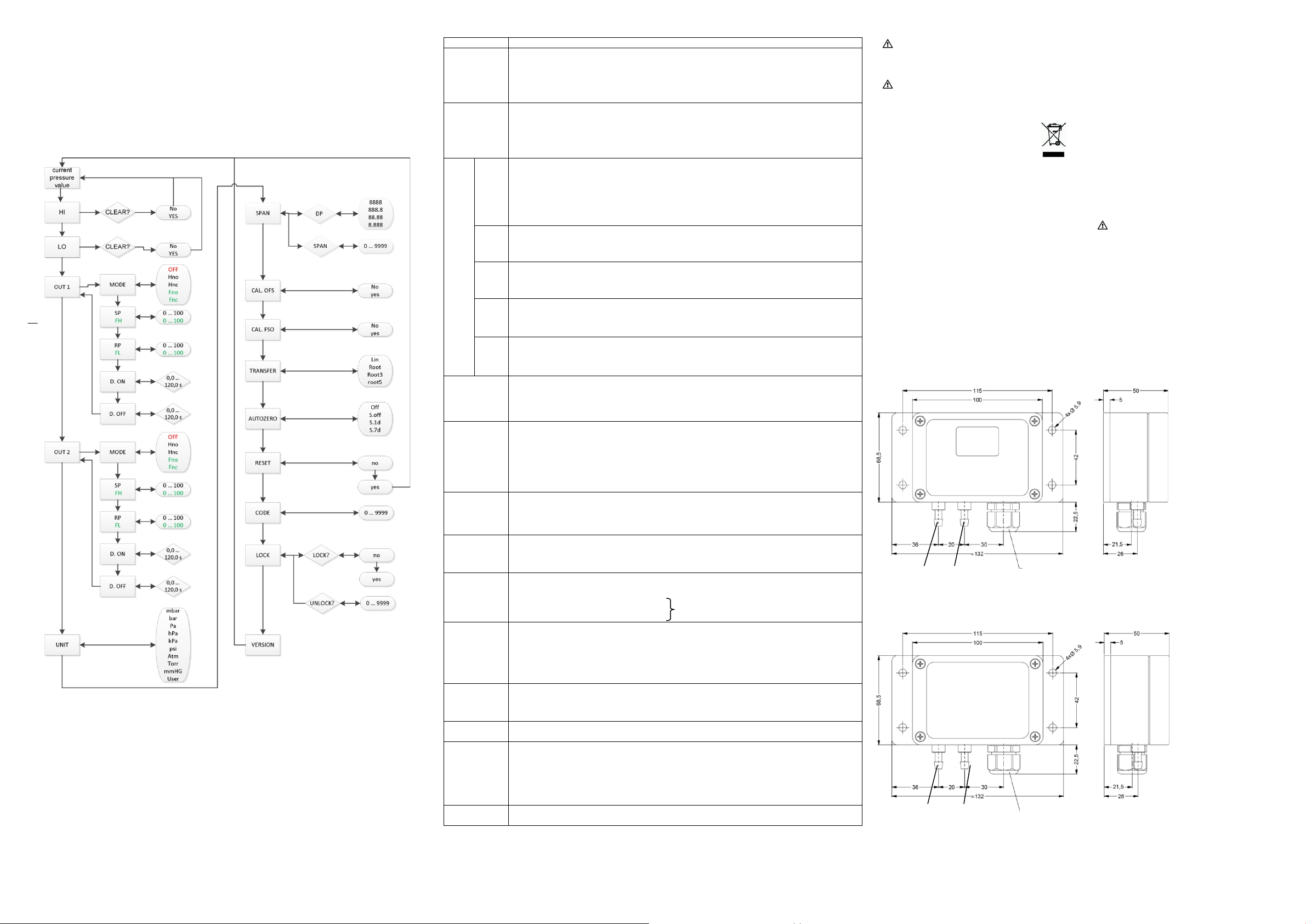
5.6 Struc
ture of menu system (from version 3.01)
5.7 Menu list
HI
LO
OUT 1
/
OUT 2
FH
Possible option: Delete value (CLEAR no / yes)
(deletes the upper and lower maximum value)
To delete the value: Press the left hand key
Possible option: Delete value (CLEAR no / yes)
(deletes the upper and lower minimum value)
To delete the value: Press the left hand key
displayed; you can select between "yes" an
Off Deactivated
Hno Hysteresis, normally open
Hnc Hysteresis, normally closed
Fno Window, normally open
Fnc Window, normally closed
OUT flashes in the lower line, in the upper line the current setting is displayed, e.g. "Hno"; the contacts can be
Setting the set points: press the left ha nd key "SP %" flashes in the lower l ine, the current value is dis-
5.6 Taking o
ut of service and disposal
WARNING! When dism antling the device, it must
always be carried out in a depress urized and currentless condition! Also check if it is necessary to
drain off the medium before dismantling!
WARNING! The medium may pose a danger to
the user. Therefore com ply with adequ ate precautions for purification.
The device must b e dispos ed of according to
the European Directives 2002/96/EG and
2003/108/EG on waste electrical and electronic equipment. Waste of electrical and
electronic equipmen t may not be disp osed of
with domestic waste!
WARNING! Dep ending on the measur ing medium,
deposits on the device may pose a danger to the
user and the environment. Comply with adequate
precautions for purification and dispose of it properly.
7 Maintenance
In principle, thi s device is maintenance-free. If required,
the housing of the device can be cleaned when it is
switched off using a damp cloth and non-aggressive
cleaning solutions.
8 Return
Before every return of your device, whether for
recalibration, decalcification, modifications or repair, it
has to b e cleaned c arefully and packed sha tter-proofed.
You have to enclose a notice of return with detailed
defect description when sending the device. If your
device came in contact with harmful substances, a
declaration of decontamination is additionally required.
Should you dispatc
decontamination
our service department regarding the used
medium, repair will not be started until an acceptable
declaration is sent.
If the device came in contact with hazardou s
substances, certain precautions have to be
complied with for purification!
h a
device without a declaration of
and
if there are any doubts in
FL
UNIT
SPAN
Cal. OFS
Cal. FSO
TRANSFER
AUTOZERO
Setting the reset points: press the left hand key
Setting the turn-on delay: press the left hand key "D. ON s" flashes in the lower line, the current value is
displayed in the upper line; it is possible to change the value between 0.0 ... 120.0 with the right hand key.
Confirm the selection with the left hand key.
Setting the return switching delay: press the left hand key "D. OFF s" flashes in the lower line, the current
value is displayed in the upper line; it is possible to change the value between 0.0 ... 120.0 with the right hand
key. Confirm the selection with the left hand key.
Units which can be set: [mbar], [bar], [Pa], [hPa], [kPa], [psi], [Atm], [torr], [mmHG], or [user]
(if the USER unit is selected, the maximum display value that is shown can be set under the menu item span)
Setting the unit: press the left hand key
Setting DP / SPAN: press the left hand key "SPAN" is displayed in the lower line, the currently set value is
displayed in the upper line; if you press the left hand button again, "DP" flashes in the lower line, 8.888, e.g. is
displayed in the upper line, the decimal point can be adjusted with the right hand key, 88.88 e.g. Confirm the
selection with the left hand key.
selected with the left hand key, the corresponding numerical value ca
(basic version ordering code -000)
Calibration of the Offset: Press the left hand key
is displayed; you can select between "yes" and "no" with the right hand key. Confirm the selection with the left
Calibration of the endpoint: Press the left hand key
(special version ordering code -600)
Lin Standard - Linear
root y = x^0.5
root3 y = x^1.5 cut off 0 … 10 %
(Value is read-only! Setting only possible via configuration switch.)
(ordering code -600)
Off no automatic zero adjustment
S. upon switching the device on
S. 1d upon switching on and after 24 hours
6. Dimensions / fixing
PCE-DDMU 10 with display
hoses with Ø 4 m m and
Ø 6 mm
Fig. 3: dimension drawing PCE-DDMU 10 with display
PCE-DDMU 10 without display
M16x1,5
9 Warranty conditions
In cases of improper use, modifications of or
damage to the device, we do not accept warranty
claims. Damaged diaphragms will not be accepted
either. Furthermore, defects due to normal wear are
not subject to warranty services.
RESET
LOCK
Reset: Press the left hand key
Activate locking code
LOCK?
key. With YES the menu is closed immediately, measured value is displayed.
(Locking code is deactivated if all values are put on 0 –
minutes or after cutting of the electrical connection
or
hoses with Ø 4 m m and
M16x1,5
Ø 6 mm
Fig. 4: dimension drawing PCE-DDMU 10 without display
 Loading...