

Page 1
User Manual
Sound Meter
PCE-428
PCE-430
PCE-432
PCE Americas Inc.
711 Commerce Way
Suite 8
Jupiter
FL-33458
USA
From outside US: +1
Tel: (561) 320-9162
Fax: (561) 320-9176
[email protected]
www.pce-instruments.com/english
www.pce-instruments.com
PCE Instruments UK Ltd.
Southpoint Business Park
Hampshire / Southampton
United Kingdom, SO31 4RF
Units 12/13
Ensign way
From outside UK: +44
Tel: (0) 2380 98703 0
Fax: (0) 2380 98703 9
Page 2

Contents
PCE-428 / 430 / 432
Contents ......................................................................................................................... 2
Appearance .................................................................................................................... 6
Buttons of Operation ....................................................................................................... 7
1. Introduction ................................................................................................................. 8
1.1 General Description ................................................................................................. 8
1.2 Applications ............................................................................................................. 8
1.3 Features .................................................................................................................. 8
1.4 Function Upgrades .................................................................................................. 9
1.5 Spectification ........................................................................................................... 9
1.6 Information for Periodic Tests ................................................................................ 12
1.7 Key Component .................................................................................................... 13
1.8 Packing List ........................................................................................................... 13
1.9 Packing Drawing ................................................................................................... 14
2. The Appearance and Operation................................................................................. 19
2.1 Keypad.................................................................................................................. 19
2.2 Microphone Connector .......................................................................................... 20
2.3 Windscreen ........................................................................................................... 21
2.4 Data and Power Supply Connector ........................................................................ 22
2.5 Battery .................................................................................................................. 23
2.6 GPS ...................................................................................................................... 24
3. Measurement Screen ................................................................................................ 26
3.1 Icons and Meaning of Screen Display .................................................................... 26
3.2 Screen of Level Meter Mode .................................................................................. 28
3.3 Screen of 1/1 Octave Mode ................................................................................... 30
2
Page 3

3.4 Screen of 1/3 Octave Mode ................................................................................... 30
PCE-428 / 430 / 432
4. Operation and Setting of the Menu ............................................................................ 32
4.1 Function ................................................................................................................ 32
4.2 Calibration ............................................................................................................. 33
4.2.1 Calibration by Measurement ............................................................................. 33
4.2.2 Calibration by Cal.Factor .................................................................................. 33
4.2.3 Conversion of Cal.Factor and Sensitivity ........................................................... 33
4.2.4 Process of Calibration by Measurement ............................................................ 34
4.3 Measurement ........................................................................................................ 36
4.3.1 MEAS.Setup ..................................................................................................... 36
4.3.2 MEAS.Range .................................................................................................... 38
4.3.3 ICCP Power ...................................................................................................... 39
4.3.4 Profile 1~3 ........................................................................................................ 39
4.3.5 Alarm Threshold ............................................................................................... 40
4.3.6 Extended Function ............................................................................................ 40
4.3.7 Statistical .......................................................................................................... 40
4.3.8 Time History ..................................................................................................... 41
4.3.9 Octave .............................................................................................................. 41
4.3.10 Custom Measure ............................................................................................ 41
4.3.11 Timer .............................................................................................................. 42
4.3.12 24h Measurement by Timer ............................................................................ 43
4.4 Setup .................................................................................................................... 44
4.4.1 Contrast............................................................................................................ 44
4.4.2 Backlight ........................................................................................................... 44
4.4.3 Battery .............................................................................................................. 44
4.4.4 Trigger .............................................................................................................. 45
4.4.5 Date & Time ...................................................................................................... 45
4.4.6 Auto PWR Off ................................................................................................... 47
4.4.7 RS-232 ............................................................................................................. 47
4.4.8 File Manager .................................................................................................... 48
3
Page 4

4.4.9 Boot Mode ........................................................................................................ 49
PCE-428 / 430 / 432
4.4.10 USB Mode ...................................................................................................... 50
4.4.11 GPS ................................................................................................................ 51
4.4.12 Setup Template ............................................................................................... 51
4.4.13 About .............................................................................................................. 52
4.5 Language .............................................................................................................. 52
4.6 Output ................................................................................................................... 52
4.6.1 AC OUT ............................................................................................................ 52
4.6.2 DC OUT ........................................................................................................... 53
4.6.3 Printer .............................................................................................................. 53
4.7 Factory Settings .................................................................................................... 54
5. RS-232 Communication Protocol .............................................................................. 55
5.1 Hardware Configuration and Settings of Interface .................................................. 55
5.2 Transfer Protocol ................................................................................................... 55
5.2.1 Start/Stop of the Block Transfer ........................................................................ 56
5.2.2 Device ID .......................................................................................................... 56
5.2.3 ATTR Attribute Character .................................................................................. 56
5.2.4 BCC (Block Check Character)........................................................................... 57
5.2.5 Block Transfer Format....................................................................................... 57
5.2.6 Recovery from Transmission Errors .................................................................. 58
5.2.7 Flow Control ..................................................................................................... 59
5.2.8 Multi-Machine Operation ................................................................................... 59
5.2.9 Rated Parameters ............................................................................................ 60
5.3 Instruction ............................................................................................................. 60
5.3.1 Instruction List .................................................................................................. 62
5.3.2 Instruction Format ............................................................................................. 65
5.3.3 Instruction Describe .......................................................................................... 66
6. Operation Notes ...................................................................................................... 100
6.1 Operation ............................................................................................................ 100
6.2 Common Issue And Solutions .............................................................................. 100
4
Page 5

6.3 Calibration ........................................................................................................... 101
PCE-428 / 430 / 432
6.4 Firmware Update ................................................................................................. 101
6.4.1 Install USB Driver ........................................................................................... 101
6.4.2 Firmware Update Procedure ........................................................................... 102
6.5 Warranty ............................................................................................................. 103
6.6 Customer Service Phone Number ....................................................................... 104
Annex 1 Glossary ....................................................................................................... 105
Annex 2 Adjustments at the Calibration Check Frequency ........................................... 107
Annex 3 Corrections for the Typical Effects of Reflections from the Case of Sound Level
Meter and Diffraction of Sound around the Microphone ................................. 108
Annex 4 Corrections of Windscreen in Free Field ........................................................ 109
Annex 5 Corrections of Electrostatic Actuator .............................................................. 110
Annex 6 Typical Frequency Response and Corresponding Upper Limit ........................ 111
Annex 7 Specification of 1/1 Octave Band Filter .......................................................... 112
Annex 8 Specification of 1/3 Octave Band Filter .......................................................... 113
Annex 9 Mid-band Frequencies for 1/1 Octave Band and 1/3 Octave Band Filters ....... 116
5
Page 6
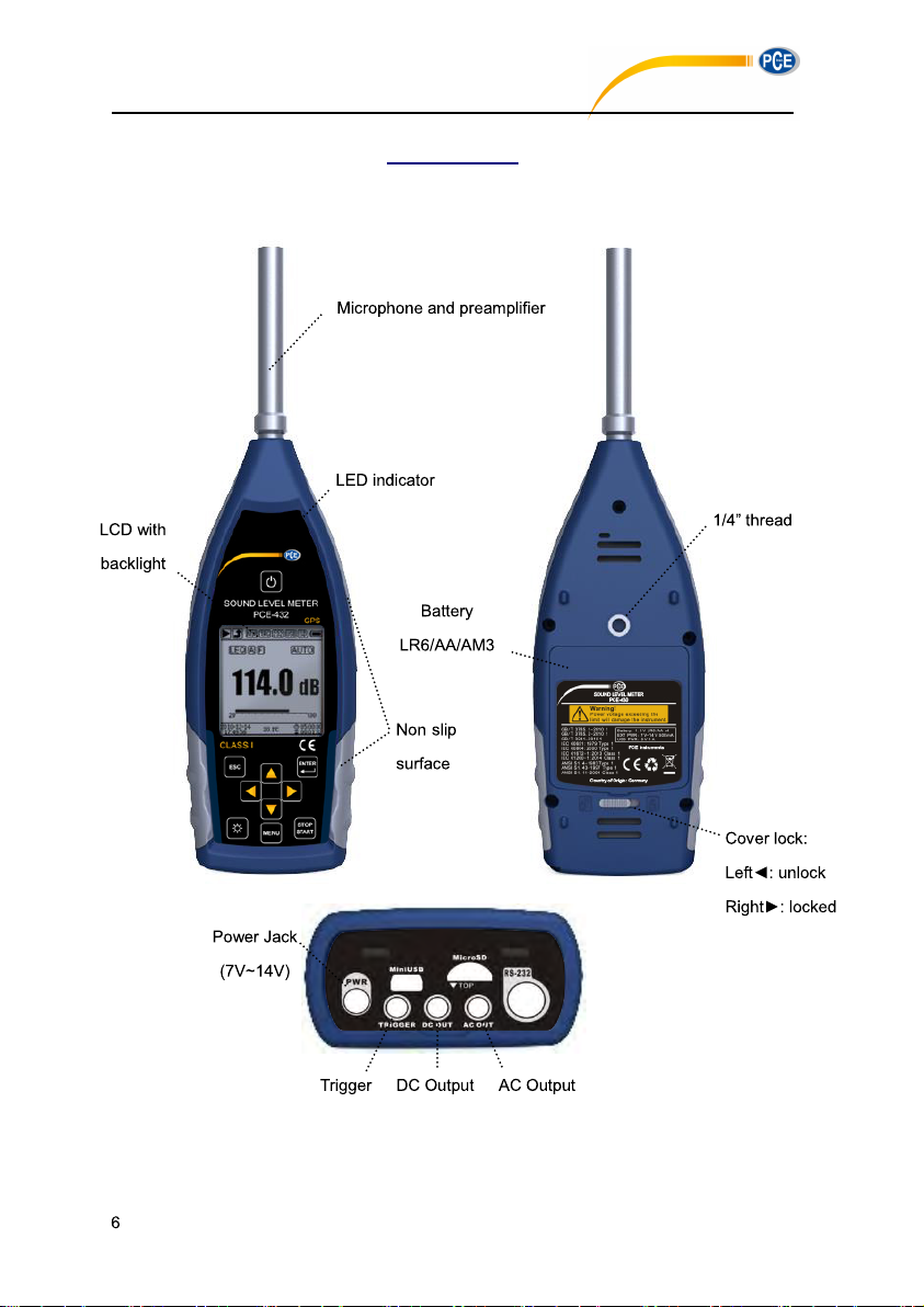
Appearance
PCE-428 / 430 / 432
-
Page 7
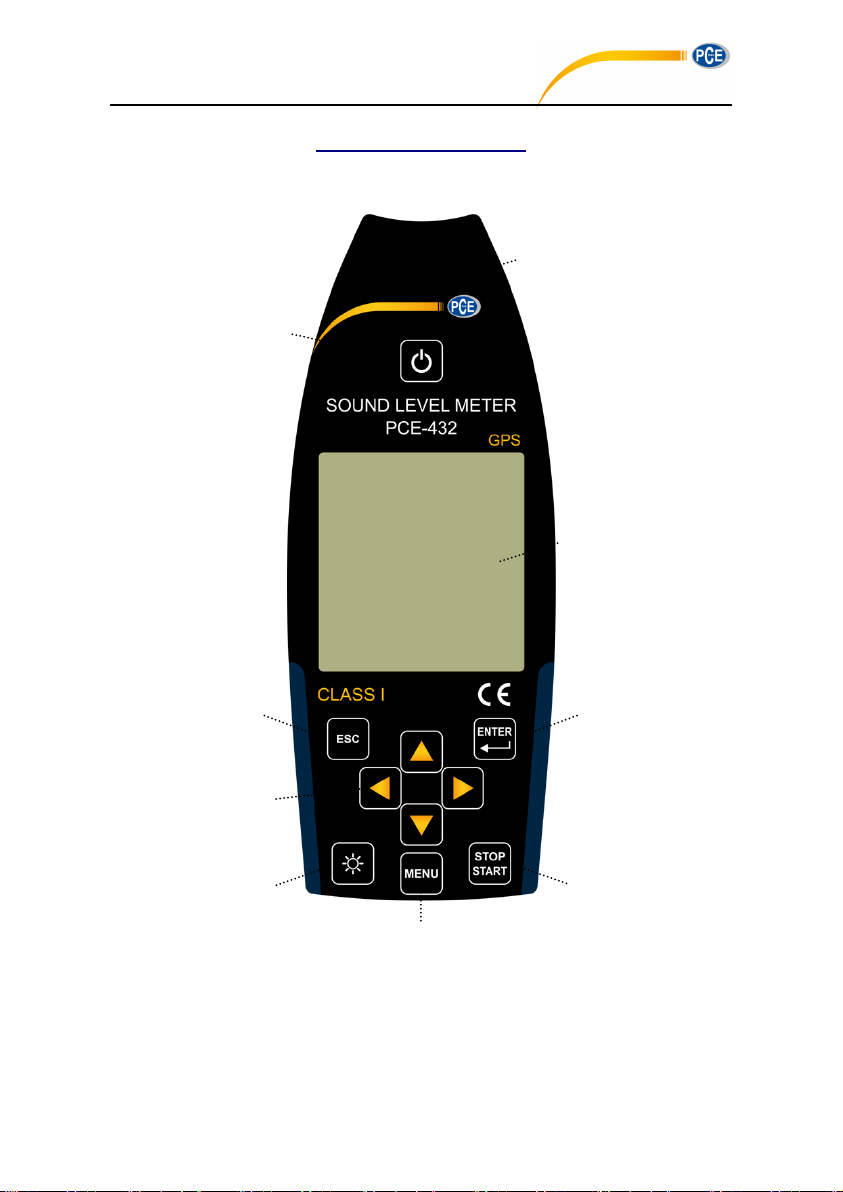
Buttons of Operation
LED indicator
<Power>
LCD Screen
<ESC>
<Enter>
Arrow keys
<▲><▼>
<◄><►>
<Menu>
<Start/Stop>
<Backlight>
PCE-428 / 430 / 432
7
Page 8
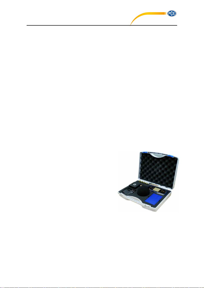
1. Introduction
PCE-428 / 430 / 432
1.1 General Description
The new PCE-428/430/432 are new generation octave sound level meter upgrade from base
PCE-428/430/432 to meet the market demand. It fulfill the 1/1 octave requirement of IEC
standard and China GB/T standard.
The PCE-428/430/432 is a digital sound level meter which design and manufacture by PCE .
The use of high precision 24 Bits AD converter makes the instruments to be an ideal choice
for performing many kinds of measurement, for example, environmental noise, vehicle noise
and industrial application.
The new types upgrade the dual-core (DSP+ARM) architecture to single chip ARM with float
point unit, and update all fix-point calculation to float-point which significantly improves the
accuracy and stability. Re-design analog front end circuit also lower the noise floor and linear
range of product. The new developed algorithm brings a single measurement range which
can cover more than 120dB dynamic range while still meets the standard.
PCE-430/432 is Class 1 and PCE-428 is Class 2. Both instruments have certificated by the
China CPA (Certification of Pattern Approval) and CMC (China Metrology Certification).
1.2 Applications
Basic noise measurement
Environmental noise assessment
Product quality check
Evaluation of noise reduction engineering
1.3 Features
Class 1 (PCE-430/432) and Class 2 (PCE-428)
sound level meter
Comply with IEC 61672-1:2013, ANSI S1.4-1983 and ANSI S1.43-1997
Real-time 1/1 and 1/3 Octave in accordance with IEC 61260-1:2014 and ANSI S1.11-2004
Linearity range: 22dBA~136dBA (PCE-430/432), 25dBA~136dBA (PCE-428)
Single range to cover 123dB (PCE-430/432) / 122dB (PCE-428) dynamic range
Frequency weighting: A/B/C/Z. Time weighting: Fast/Slow/Impulse
3-Profile and 14 custom define measurement are calculate in parallel with different
8
Page 9
frequency/time weighting
Single chip high speed ARM with FPU
USB port function implemented
White backlight LCD
Update firmware via USB (also power supply)
Integral period from 1s~24h
Timer feature support auto measurement
0.1s, 0.2s, 0.5s logger step added
Internal GPS (option) with GPS timing
5 templates to save user setting
Single range to cover 123dB dynamic range
B-weighting added to for ANSI standard
Reduce the noise floor (only for Class 1)
Automatic power on with external
supply, ease of integration
Upper limit of measurement:
136dBrms/139dBpeak (40mV/Pa)
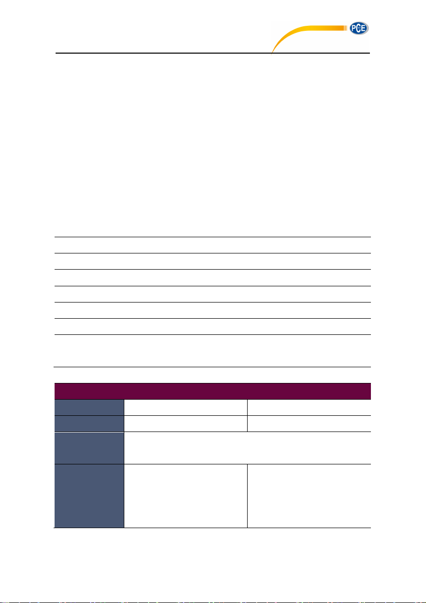
Specifications
Type
Accuracy
Class 1 (Group X)
Class 2 (Group X)
Standard
GB/T 3785.1-2010, IEC 60651:1979, IEC 60804:2000
IEC 61672-1:2013, ANSI S1.4-1983, ANSI S1.43-1997
Octave1
Real-time 1/1 Octave: 8Hz~16kHz
Real-time 1/3 Octave (Option): 6.3Hz~20kHz
GB/T 3241-2010, IEC 61260-1:2014
ANSI S1.11-2004. Base 10 system.
Real-time 1/1 Octave: 20Hz~8kHz
Real-time 1/3 Octave (Option): 20Hz~12.5kHz
GB/T 3241-2010, IEC 61260-1:2014
ANSI S1.11-2004. Base 10 system.
PCE-428 / 430 / 432
Calculate SPL, LEQ, Max, Min, Peak, SD, SEL, E
LN statistical and time history curve display
User define integral period measurement, integral period up to 24h
High speed ARM core with FPU (Float Point Unit) to achieve wide frequency response,
large dynamic range and low noise floor
4G MicroSD card (TF card) mass storage
RS-232 remote control port
Mini thermal printer for measurement data print
Internal GPS module (option), support GPS timing
1.4 Function Upgrades
1.5 Spectification
PCE-430/432 PCE-428
9
Page 10
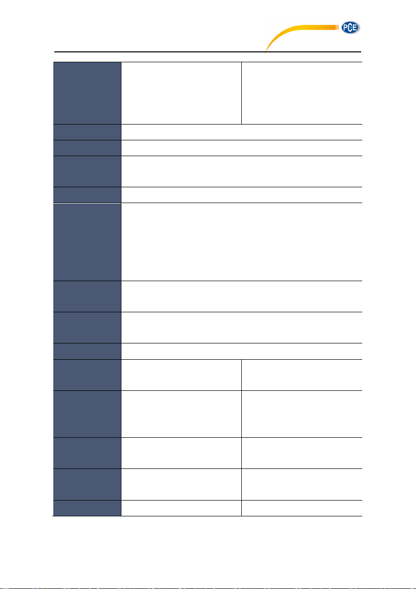
Supplied
Microphone
MPA231T: 1/2” prepolarized
measurement microphone, Class
1. Sensitivity: 40mV/Pa. Frequency
Range: 3Hz~20kHz.
MPA309T: 1/2” prepolarized
measurement microphone, Class
2. Sensitivity: 40mV/Pa. Frequency
Range: 20Hz~12.5kHz.
Mic Interface
TNC connecter with ICCP power supply (4mA)
Detector / Filter
Fully float-point digital signal processing (digital detector and filter)
Integral Period
Infinite or 1s~24h user define integral period.
Repeat time: Infinite or 1~9999
Logger Step
0.1s, 0.2s, 0.5s, 1s~24h
Measurement
Functions
L
XY(SPL)
, L
Xeq
, L
XYSD
, L
XSEL
, LXE, L
XYmax
, L
XYmin
, L
XPeak
, L
XYN
. Where X is
the frequency weighting: A, B, C, Z; Y is time weighting: F, S, I; N is the
statistical percentage: 1~99. 3-Profile and 14 custom define
measurement are calculate in parallel with different frequency/time
weighting
24h Measurement
Automatic measurement based on user define date/time and save the
history data
Frequency
Weighting
Parallel A, B, C, Z (It can also be applied to 1/1 and 1/3 Octave)
Time Weighting
Parallel F, S, I and Peak detection
Self-Noise2
Sound: 19dB(A), 25dB(C), 31dB(Z)
Electrical: 13dB(A), 17dB(C), 24dB(Z)
Sound: 20dB(A), 26dB(C), 31dB(Z)
Electrical: 14dB(A), 19dB(C), 24dB(Z)
Upper Limit2
136dB(A)
Increase to 154dB(A) with 5mV/Pa
Microphone
136dB(A)
Increase to 154dB(A) with 5mV/Pa
Microphone
Frequency
Response1
10Hz~20kHz
20Hz~12.5kHz
Level Linearity
Range
2, 3, 4
22dB(A)~136dB(A)
Octave: 30dB~136dB
25dB(A)~136dB(A)
Octave: 33dB~136dB
Dynamic Range2
123dB (13dB(A)~136dB(A))
122dB (14dB(A)~136dB(A))
PCE-428 / 430 / 432
10
Page 11
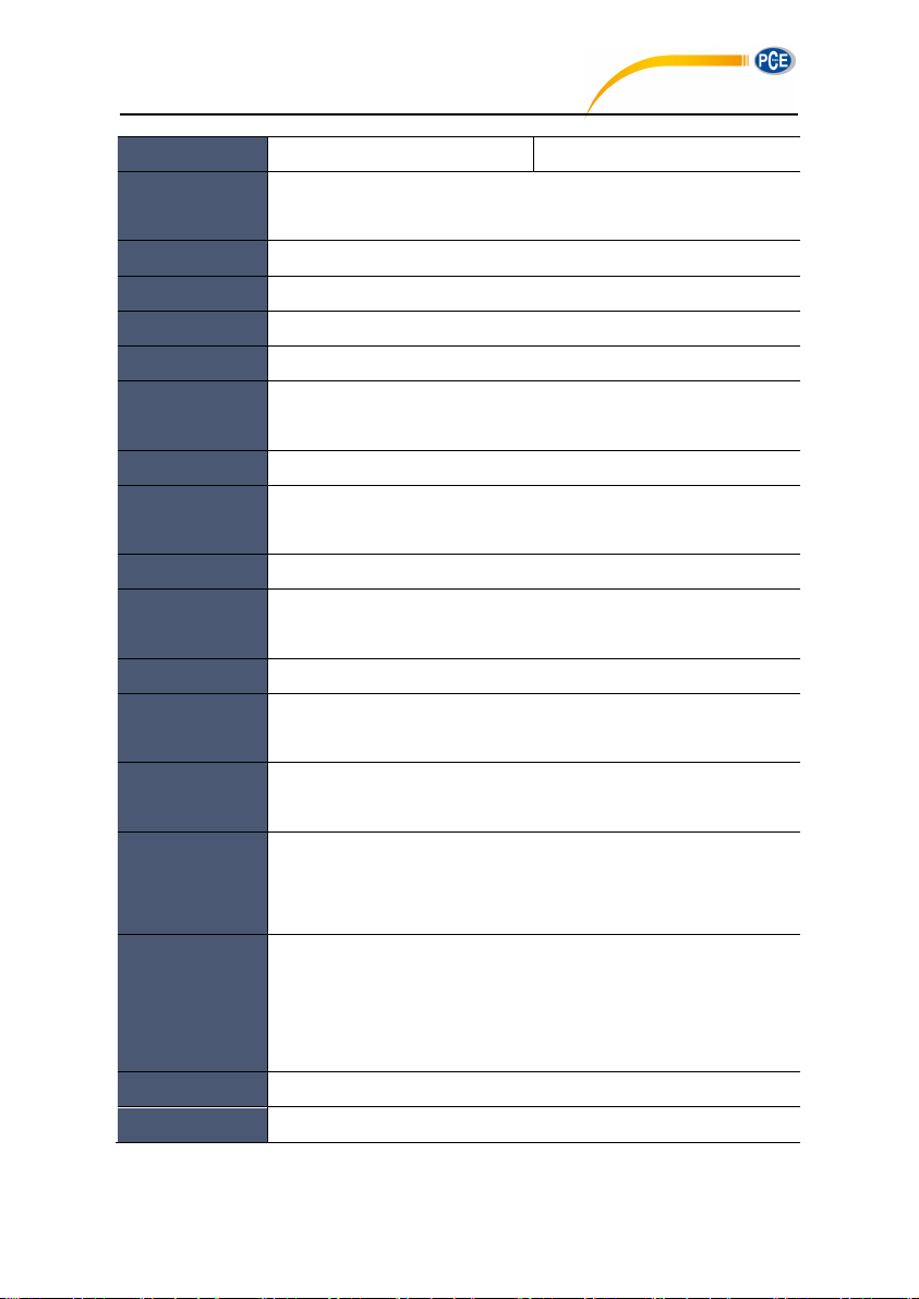
Peak C Range
2, 3
47dB~139dB
50dB~139dB
Electrical Input
Maximum input voltage: 5Vrms (7.07Vpeak). Input impedance of
preamplifier: >6GΩ
Range Setting
Single range to cover whole dynamic range
Resolution
24Bits
Sampling Rate
48kHz (Sampling interval for LN: 20ms)
Time History
Time domain noise curve display. Duration time: 1min, 2min, 10min
LCD Display
160x160 LCD with white backlight, 14 step contrast level, 1s display
update rate
Mass Storage
4G MicroSD card (TF card)
Post-Processing
Post-processing software VA-SLM can read, analyze and generate
reports of store data.
Export Data
Directly connect to the computer to read the memory card (USB disk)
Output
AC Output (max 5V
RMS
, ±15mA), DC Output (10mV/dB, max 15mA),
RS-232 serial interface and USB (USB disk mode or modem mode)
Alarm
User define alarm threshold. LED indicate the alarm status
Setup Template
5 templates to save user setup for different application, template can be
save in MicroSD card
Auto Power On
Automatic power on and start measurement when power supply
available, ease of integration
Power Supply
4x1.5V alkaline batteries (LR6/AA/AM3), sustainable use of approx.10
hours (depends on battery). It also can be supply by external DC power
(7V~14V 500mA) and USB power (5V 1A)
RTC
Built-in backup battery has been calibrated at factory to the error <26s in
30days (<10ppm, (25±16) ºC). It can keep RTC running when replacing
the main batteries.
GPS timing function available (option with GPS module)
Language
English, Chinese, Portuguese, Spanish, German, French
Firmware Update
Update firmware via USB port
PCE-428 / 430 / 432
11
Page 12
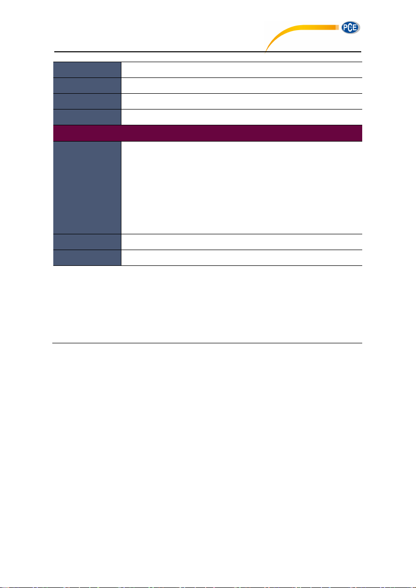
Conditions
Temperature: -10ºC~50ºC. Humidity: 20%~90%RH
RT Temperature
Real-time temperature display on the main screen
Size (mm)
W70 x H300 x D36
Weight
Approx. 620g, including 4 alkaline batteries
Option
GPS
Receiver Type: 50 Channels; Time-To -First-Fix: Cold Start 27s, Warm
Start 27s, Hot Start 1s; Sensitivity: Tracking -161dBm, Reacquisition
-160dBm, Cold Start -147dBm, Hot Start -156dBm; Horizontal position
accuracy: 2.5m, Timing accuracy: 30ns, Velocity accuracy: 0.1m/s;
Update Rate: 1Hz, Operation Limits: Dynamic≤4g, Altitude<50000m,
Velocity<500m/s
Calibrator
CA111, Class 1, 94dB/114dB, 1kHz
Printer
Mini thermal or dot-matrix printer, RS-232 port
Note 1: Ignore the result outside 20Hz~12.5kHz for type PCE-428 alone due to microphone
frequency response of Class 2.
Note 3: Measurement according to GB/T 3785 and IEC 61672.
Note 4: Measurement according to GB/T 3241 and IEC 61260.
PCE-428 / 430 / 432
Note 2: The data was measured with 40mV/Pa microphone for PCE-430/432 and PCE-428.
1.6 Information for Periodic Tests
Reference sound level: 94.0dB.
Reference incidence direction: parallel to the incident direction of the microphone.
Reference point of microphone: the central point of microphone diaphragm.
Reference incidence direction: direction perpendicular to the microphone diaphragm.
Reference attenuation of octave spectra: 0dB.
Reference input signal level of octave spectra: 40mV (94dB for sensitivity of 40mV/Pa).
12
Page 13
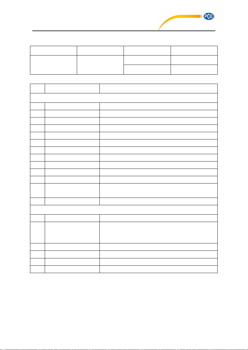
1.7 Key Component
Component Name
Manufacturer
Type
Description
Microphone
MP231
Class 1 microphone
MP309
Class 2 microphone
No.
Type
Description
Standard
1
Sound level meter without microphone
2
CC308 Case
Carrying case
3
MA231T
ICCP preamplifier with TNC connector
4
MP231/MP309
Class 1 (308) or class 2 (309) microphone
5
WS002-9 Windscreen
90mm diameter windscreen for 1/2” microphone
6
MicroSD Card
4G memory card to store data
7
Battery
Alkaline battery (LR6 / AA / AM3) x 4
8
Power Adapter
Power adapter with 9V/500mA
9
MiniUSB Cable
Use to connect computer
10
Quick Start Guide
Quick start guide
11
Certificate of Calibration
Certificate of factory calibration
12
CD
Include post-process software, user manual (pdf), driver,
firmware and other utility
13
Certificate of Conformity
Certificate of conformity
Option
14
GPS
GPS module and antenna
15
Sound Calibrator
CA111: class 1 calibrator, 94dB/114dB
CA114: class 2 calibrator, 94dB
CA115: class 2 calibrator, 11 4dB
16
Thermal Printer
Mini thermal printer without ribbons, RS232 connector
17
Tripod
Stand for sound level meter
18
Printed User Manual
Printed user manual
19
Test Report
Test report from metrology institute
PCE-428 / 430 / 432
1.8 Packing List
PCE-428/430/432
PCE Instruments
13
Page 14
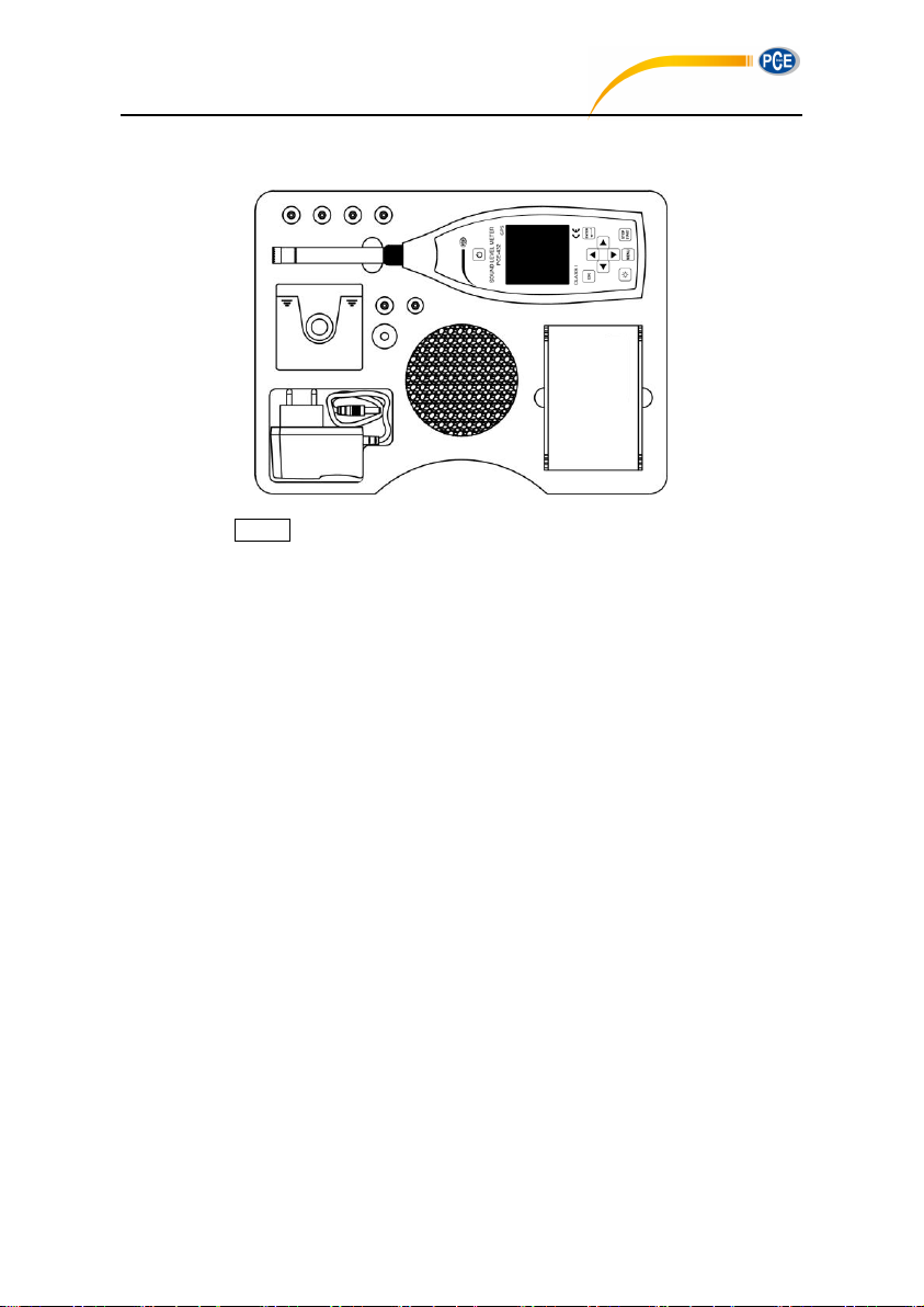
1.9 Packing Drawing
PCE-428 / 430 / 432
☆Note: The detail of packing items may vary to follow orders.
14
Page 15
2. The Appearance and Operation
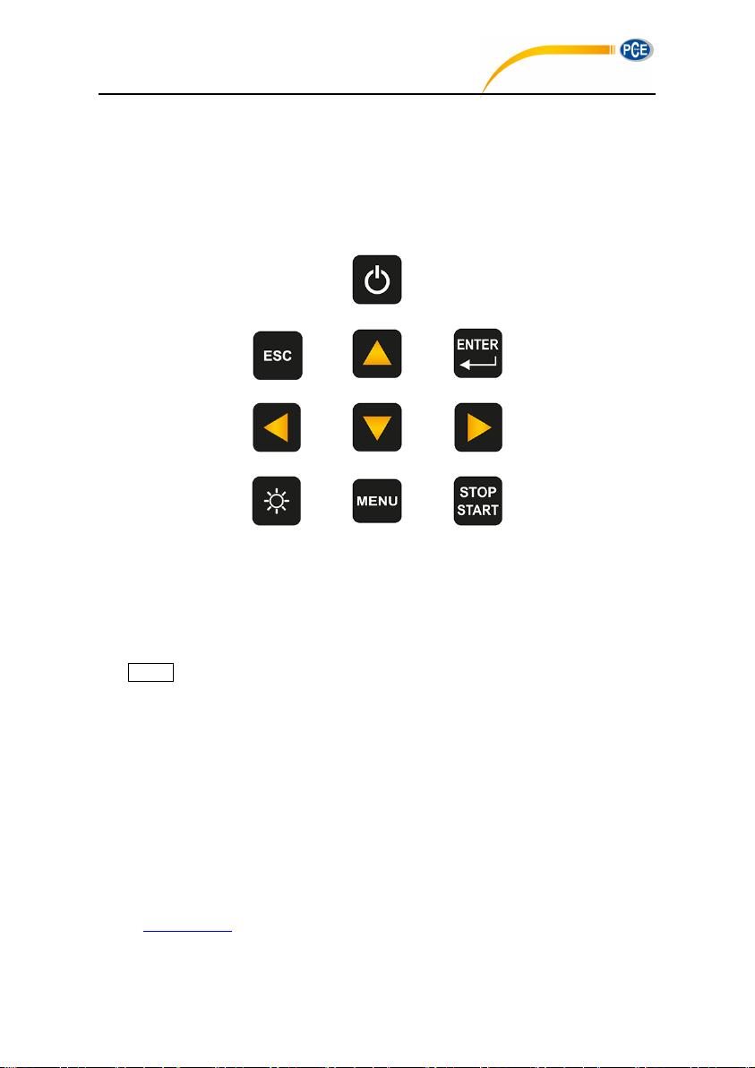
<Power>
<ESC>
<▲>
<Enter>
<◄> <▼> <►>
<Backlight>
<Menu>
<Start/Stop>
PCE-428 / 430 / 432
PCE-428/430/432 uses the same body and the keypad layout. LCD screen, keypad and LED
indicators lay on the front of instrument.
2.1 Keypad
Sound level meter has 10 keys, namely:
<Power>:
Long press 2 seconds of this key will power on the sound level meter. When sound level
meter keep in stop state, long press 2 seconds will trigger the shut-down-dialog-box, and
then press <Enter> to power off sound level meter.
☆Note: <Enter> is invalid when the sound level meter is running measurement.
<ESC>:
Exit the menu or return to previous menu. Press <ESC> also can clear the history curve
at the time history screen.
<Enter>:
Enter the menu of next level, or confirm the changes of the parameters, or save current
data as CSD format in stop state.
<Backlight>:
Press to open or close the LCD backlights. Backlight delay can be set in the menu. Refer
to 4.4.2 Backlight to earn more details.
19
Page 16

<Start/Stop>:
PCE-428 / 430 / 432
Start or stop the measurement.
<▲>:
Up arrow used to select the menu item or adjust the parameters.
<▼>:
Down arrow used to select the menu item or adjust the parameters.
<◄>:
Left arrow used to select the menu item, or adjust the parameters, or switch measure
screens.
<►>:
Right arrow used to select the menu item, or adjust the parameters, or switch measure
screens.
<Menu>:
Press to enter the main menu list.
2.2 Microphone Connector
The TNC connector on the top of the sound level meter is used to connect to microphone and
preamplifier (microphone and preamplifier are usually mounted together). The TNC is
threaded coaxial connector.
PCE-430/432 is equipped with Class 1 microphone, while PCE-428 is equipped with Class 2:
MPA231T:
MPA309T:
20
1/2” pre-polarized measurement microphone, class 1. Sensitivity: 40mV/Pa. Frequency
range: 3Hz~20kHz. Mounted with ICCP preamplifier and powered by 4mA/24V.
1/2” pre-polarized measurement microphone, class 2. Sensitivity: 40mV/Pa. Frequency
range: 20Hz~12.5kHz. Mounted with ICCP preamplifier and powered by 4mA/24V.
Page 17

Microphone and preamplifier are mounted together by thread. Unless special situation,
PCE-428 / 430 / 432
please do not separate each other. The microphone is a precision measurement sensor,
long-term exposure to high humidity or dust environment would impact microphone.
Microphone that is not in use should be placed in a attached box.
The microphone is ICCP power supply. The supply current specifications are 4mA, voltage
24V. It will damage the microphone if voltage over 30V. PCE-428/430/432 sound level meter
has internal ICCP power which can connect to microphone directly.
Insert microphone to TNC connector. Then rotate the thread until the connection is tight.
2.3 Windscreen
Sound level meter equipped with WS002-9 windscreen for use in windy outdoor
environments. No need to use windscreen when used in a windless environment (such as
indoor measurement).
Insert the windscreen onto the microphone until stop according to above diagram. Refer to
Annex 4 Corrections of Windscreen in Free Filed to earn more detail.
21
Page 18

2.4 Data and Power Supply Connector
PCE-428 / 430 / 432
There are 7 interfaces at the bottom of the sound level meter. Open the rubber cover to see
these interfaces.
PWR:
Power connector, using the standard DC socket (2.1mm core diameter), can connect to
the 7~14V 500mA external power supply.
☆Note: Exceed 14V could damage the sound level meter!
MiniUSB:
MiniUSB port which connects to a computer can be select as USB Disk Mode or
Modem Mode, refer to 4.4.10 USB Mode to earn more detail. Additional, MiniUSB can
be used as another external power, but the power supply must meet the requirement of
5V/1A.
USB Disk Mode:The files inside the MicroSD card can be access directly at this mode,
no need to install driver.
Computer can recognize the MiniUSB as serial port (virtual serial port, need to install
driver) and communicate with sound level meter by RS-232 protocol, refer to 5. RS-232
Communication Protocol to earn more detail.
☆Note:At least 1A power current capacity must be meet for power supply and cable
(cable with ferrite core is not recommend for power supply). Please select the working
mode in time after connected to the computer. Otherwise, the computer can’t recognize
the USB. The MiniUSB and RS-232 port cannot working at the same time when select
Modem Mode.
MicroSD:
MicroSD socket, standard MicroSD card can be used to store SWN, OCT and CSD files.
Recommend to use card-reader to format the MicroSD card, rather than format it at the U
22
Page 19

Disk Mode. Note that the MicroSD card provides with the sound level meter has already
PCE-428 / 430 / 432
formatted before sale.
☆Note: Keep front side (with silk screen) of MicroSD card down to insert without
hot-plug.
RS-232:
It can be use as standard RS-232 port at Remote mode, and also can be used to
connect thermal printer as Printer mode. Refer to 4.6.3 Printer and 5. RS-232
Communication Protocol to earn more detail.
TRIGGER:
Trigger input interface using a standard 3.5mm headphone jack. Refer to 4.4.4 Trigger to
earn more detail.
DC OUT:
DC output interface using a standard 3.5mm headphone jack. Refer to 4.6.2 DC OUT to
earn more detail.
AC OUT:
AC output interface using a standard 3.5mm headphone jack. Refer to 4.6.1 AC OUT to
earn more detail.
2.5 Battery
Recommend to use 4 cell of alkaline battery (LR6/AA/AM3), paying attention to the battery
polarity (+/-) marked in the battery compartment. Do not mix using of old and new batteries at
the same time. Remove batteries when the device is not in use. The total voltage of 4 cell
battery cannot exceed 14V, otherwise it will damage the sound level meter.
The real test shows that the 4 cell of alkaline battery can support sustainable use of
approx.10 hours (depends on battery) for sound level meter. When use rechargeable battery
Eneloop BK-3HCCA/4BC (Rated capacity 2450mAh), sound level meter can work about 12
hours continuously. When the battery voltage is lower than the minimum voltage requirement
of the sound level meter, it will shut down automatically.
We recommend using external power supply or USB-power-bank rather than batteries for
long time running.
Follow the figure below to install or replace the battery:
23
Page 20

PCE-428 / 430 / 432
Turn the button to the left side to unlock the battery compartment cover. Then lift the cover to
open it.
Close and lock the battery compartment after change the battery.
2.6 GPS
GPS antenna cover located on the top surface of sound level meter which select GPS
function as option module.
☆Note: GPS function must be select before delivery to user due to install GPS module
should return the sound level meter to factory.
GPS performance is mainly affected by two factors: the satellite ephemeris and the satellite
signal noise ratio.
24
Page 21

Satellite Ephemeris: GPS satellites orbit information. According to ephemeris, satellite
PCE-428 / 430 / 432
positioning signal and time, the current location can be determined. Ephemeris need to
download from the GPS satellites, but the download speed is very low (approx. 50bps),
and vulnerable to the impact of satellite signal strength. The high bit error rate may lead to
a longer time of download ephemeris, and even download fail. The sound level meter can
keep the ephemeris data in memory for approx. 30 minute after turn off GPS module. The
ephemeris data is only is valid within 2 hours.
Satellite Signal Noise Ratio: Satellite positioning signal intensity. In rainy days or indoor,
signal strength will be affected.
GPS have 3 boot modes: Cold start, warm start and hot start
Cold Start: First location, need to download the latest ephemeris and longer time.
Warm Start: GPS module has the last saved location information, but need to
re-download the ephemeris due to expired. Warm start needs almost same time as cold
start.
Hot Start: GPS module has valid ephemeris and can reposition in a very short time.
25
Page 22
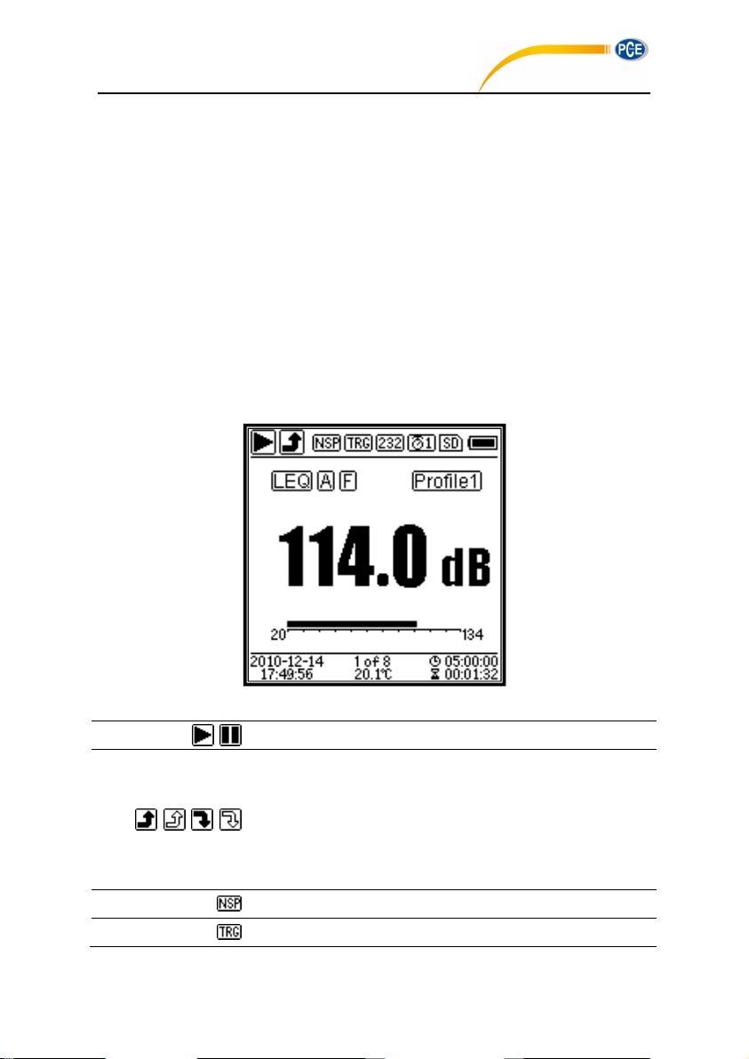
3. Measurement Screen
Start/Stop. Describe the measurement state.
Overload indicator and under-range indicator. Solid arrow
indicates that the current state is overload / under-range. Hollow
arrow indicates that overload / under-range event have occurred
within the integral period。At the beginning of the new integral
period, overload and under-range indicator icon will be clear.
ICCP power state. Displayed when ICCP is turn off.
Trigger state. Displayed when trigger is enable.
PCE-428 / 430 / 432
Sound level meter has three measurement modes: Level Meter, 1/1 Octave, 1/3 Octave.
User can select it in the menu of Function.
Level Meter has 8 screens which can be switch through <◄>, <►>. The 8 screens are: Main,
3-Profiles, LN Statistical, Time History, Custom Measurement Page 1, Custom Measurement
Page 2, GPS Page 1 and GPS Page 2.
1/1 Octave has 6 screens: Octave Histogram, Octave Table Page 1~3, GPS Page 1 and
GPS Page 2.
1/1 Octave has 7 screens: Octave Histogram, Octave Table Page 1~4, GPS Page 1 and
GPS Page 2.
3.1 Icons and Meaning of Screen Display
All icons of Main screen is enable, the meaning of each icons are describe as following:
26
Page 23
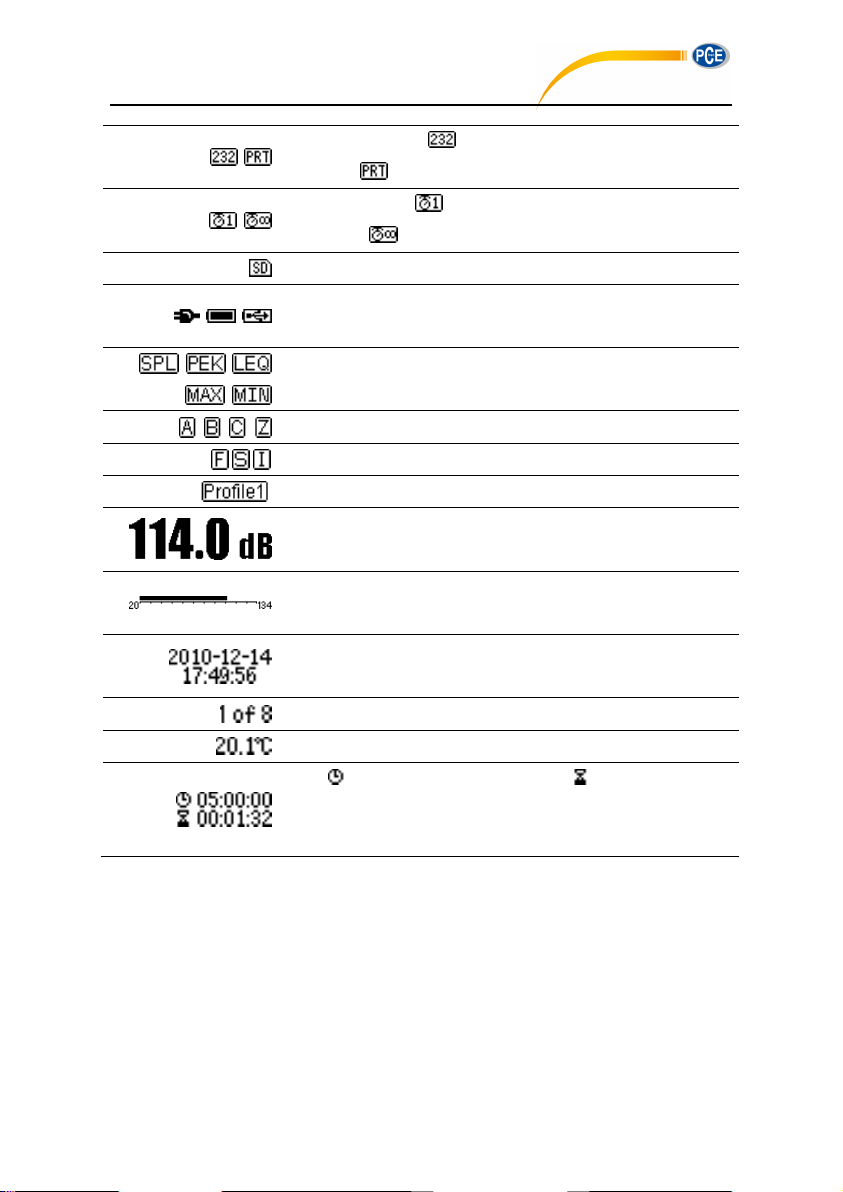
RS-232 state. Icon will be displayed at the Remote mode,
and icon will be displayed at Printer mode.
Timer state. Icon means the timer is enabled and only run
once. Icon means the timer is enabled and run in loop.
MicroSD state. Displayed when enable the MicroSD storage.
Power state. The icons form left to right: external power supply,
battery supply (with voltage display) and USB power supply.
Calculation mode of measurement.
Filter state.
Detector state.
Icon of Profile. Indicate the profile number of current display.
Measurement value.
Visualize and dynamic bar graph display of measurement values
within the current range.
Date and time.
Current page number and total page number.
Internal temperature display.
Icon means the integral period, icon means the elapsed
time. The measurement stop when elapsed time equal to total
measurement time (Itg.Period * Repeat).
Icons in the same row will display one at the same time. All icons can be display on each
PCE-428 / 430 / 432
screen and keep the same meaning.
27
Page 24
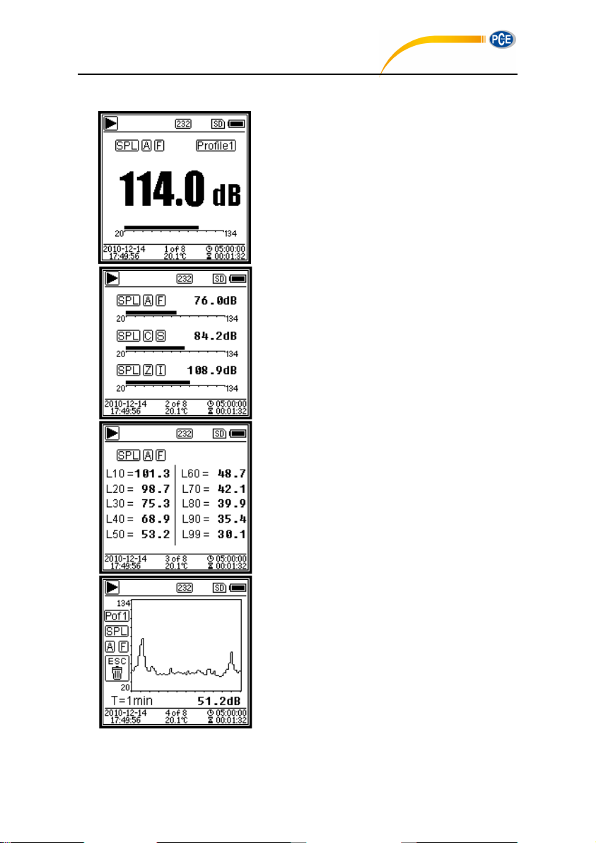
3.2 Screen of Level Meter Mode
Main screen. Display the measurement
data, filter, detector, mode and Profile
number. Main screen only display one
group data of 3-Profile. Press <▲>,
<▼> to switch within 3-Profile.
3-Profile. Display the data and
corresponding mode, filter and detector
of 3-Profile measurement at the same
time. 3-Profile data can be saved into
SWN file.
LN Statistical. Display 10 groups of
statistical results. Each group of data
sources (fix mode to SPL, filter and
detector can be customize) and the
percentage value can be set through
the menu.
Time History. Display the current noise
value and time domain curve. The data
sources (one of 3-Profile) and the
time-line length (1min, 2min and 10min)
can be customize.
Press <ESC> to clear the screen and
re-display the curve.
PCE-428 / 430 / 432
28
Page 25
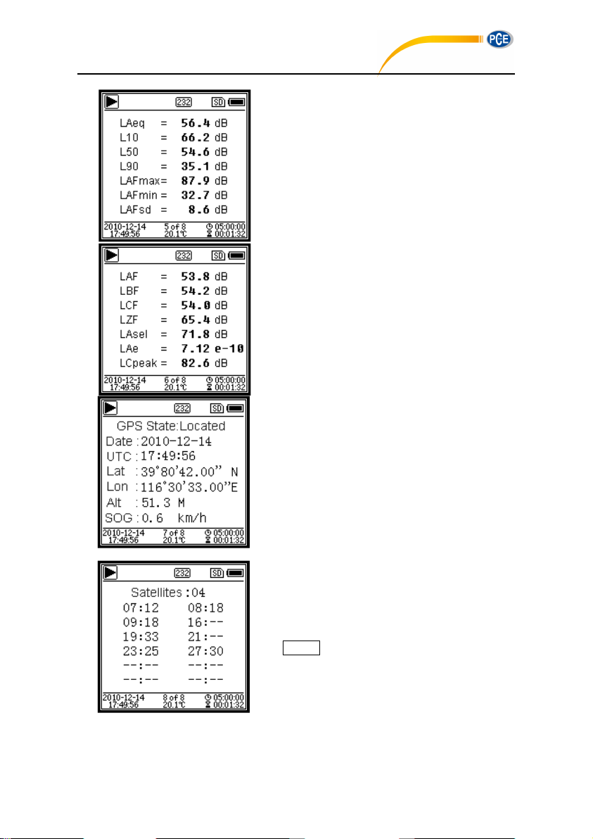
Custom Measurement Page 1. User
can set the parameters of the 14 sets of
measurement. This screen can display
the first 7 sets.
Custom Measurement Page 2. User
can set the parameters of the 14 sets of
measurement. This screen can display
the last 7 sets.
GPS Page 1. Display GPS information:
GPS state, GPS date, GPS time,
latitude, longitude, altitude and speed.
GPS Page 2. Display number of satellite
which contribute to positioning, and
signal noise ratio of all visible satellites
(0dB~99dB).
☆ Note: Number of visible satellites
may be greater than the number of
positioning satellites due to some
satellites is unavailable for positioning.
PCE-428 / 430 / 432
29
Page 26
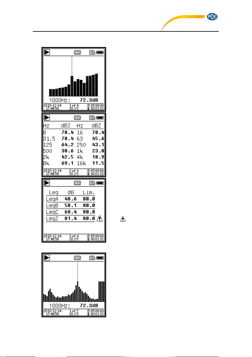
3.3 Screen of 1/1 Octave Mode
1/1 Octave Spectra. Display 12 bands
of 8Hz~16kHz and L
Aeq
, L
Beq
, L
Ceq
, L
Zeq
as bar graph. Press <▲>, <▼> to
display the detail value of each band. A
threshold can be set for each band. The
LED indicator will turn red when the
data exceed the threshold.
Octave Table Page 1. Display the
measurement data of 8Hz~16kHz. The
LED indicator will turn red and dB value
will display as invert color when the data
exceed the threshold.
Octave Table Page 2. Display the
measurement data of L
Aeq、LBeq、LCeq
、
L
Zeq
. The LED indicator will turn red and
will be display when the data
exceed the threshold.
1/3 Octave Spectra. Display 36 bands
of 6.3Hz~20kHz and L
Aeq
, L
Beq
, L
Ceq
,
L
Zeq
as bar graph. Press <▲>, <▼> to
display the detail value of each band. A
threshold can be set for each band. The
LED indicator will turn red when the
data exceed the threshold.
PCE-428 / 430 / 432
3.4 Screen of 1/3 Octave Mode
30
Page 27
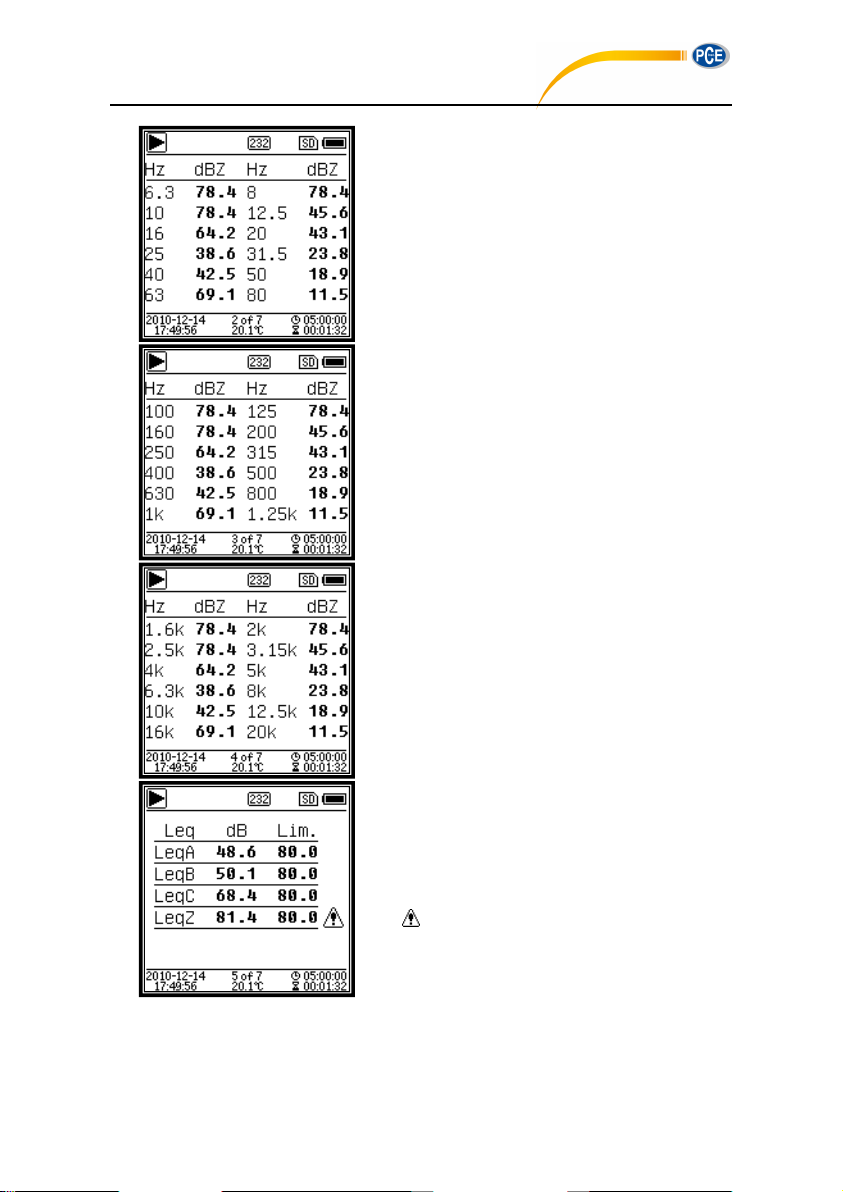
Octave Table Page 1. Display the
measurement data of 6.3Hz~80Hz. The
LED indicator will turn red and dB value
will display as invert color when the data
exceed the threshold.
Octave Table Page 2. Display the
measurement data of 100Hz~1.25kHz.
The LED indicator will turn red and dB
value will display as invert color when
the data exceed the threshold.
Octave Table Page 3. Display the
measurement data of 1.6kHz~20kHz.
The LED indicator will turn red and dB
value will display as invert color when
the data exceed the threshold.
Octave Table Page 4. Display the
measurement data of L
Aeq、LBeq、LCeq
、
L
Zeq
. The LED indicator will turn red and
will be display when the data
exceed the threshold.
PCE-428 / 430 / 432
31
Page 28
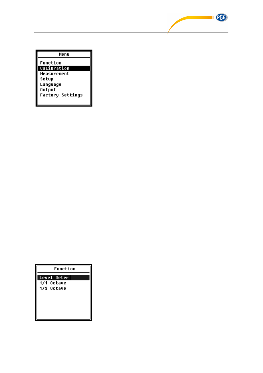
4. Operation and Setting of the Menu
PCE-428 / 430 / 432
Press <Menu> to access the next level menu. All parameters
related to measurement can be set in the menu.
Menu Tree
4.1 Function
32
Select Function and press <Enter> to enter this menu. 3 kind
of measurement can be select: Level Meter, 1/1 Octave and
1/3 Octave. Press <▲>, <▼> can select mode of
measurement. Press <Enter> to save setting and return to
previous menu. Press <ESC> to return to previous menu.
Page 29
4.2 Calibration
PCE-428 / 430 / 432
Select Calibration and press <Enter> to enter this menu.
Many factors include temperature, humidity and air pressure
will impact the microphone's sensitivity. Therefore, user must
run calibration at least once before measurement.
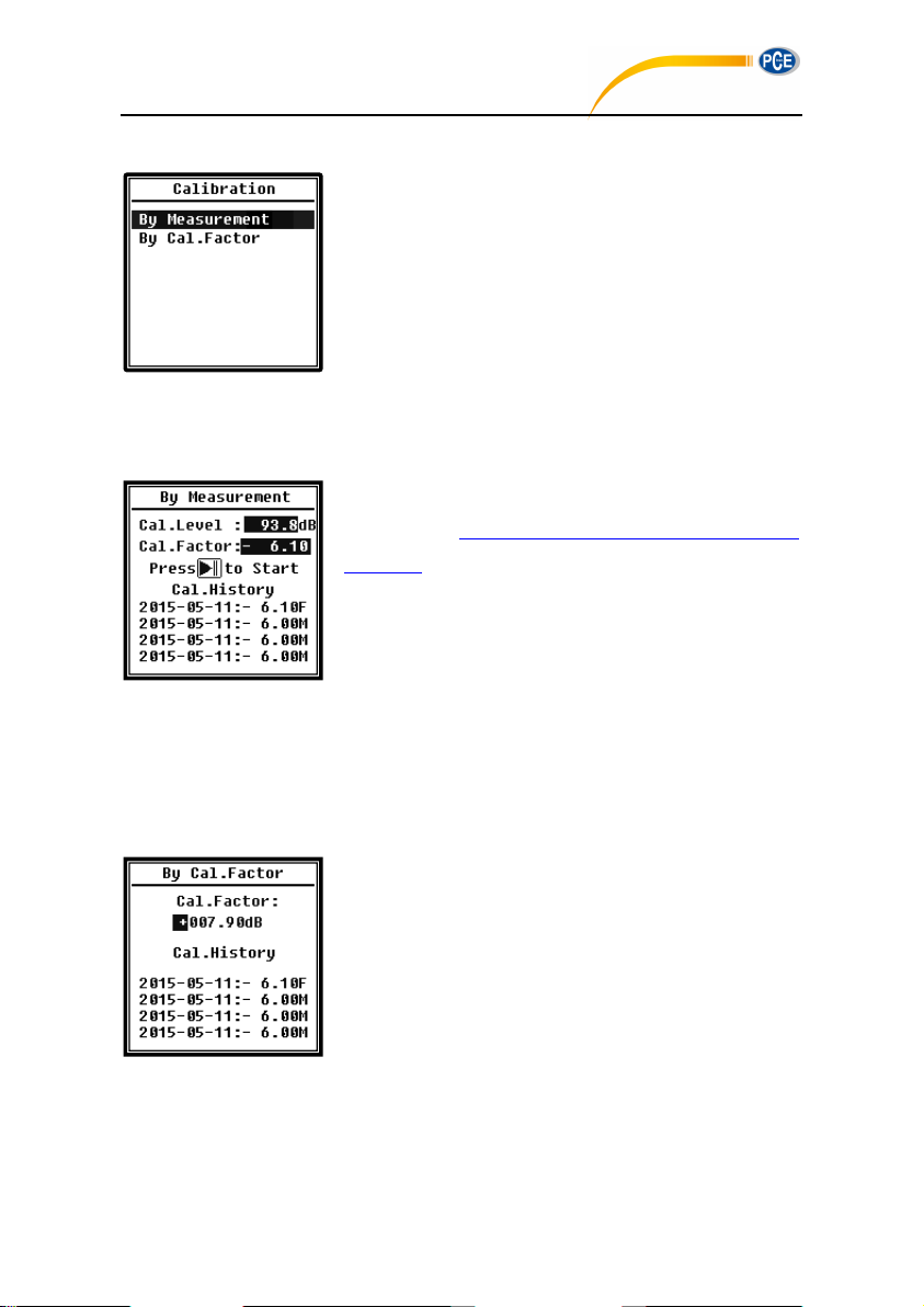
There are two calibration methods: By Measurement and By
Cal.Factor. Method of By Measurement is recommend for
calibration with sound calibrator. Method of By Cal.Factor can manually adjust the calibration
factor by user.
4.2.1 Calibration by Measurement
Select By Measurement and press <Enter> to enter this
menu. Refer to Annex 2 Adjustments at the Calibration Check
Frequency to earn more detail of the stated calibrator and
corresponding adjustment value.
Cal.Level can be adjusted between 0dB~199.9dB. Press <◄>,
<►> and <▲>, <▼> can change the Cal.Level and press
<Start> to start calibration. After calibration finished, the new Cal.Factor will be update as the
result and user can press <Enter> or <ESC> to save or ignore this result. This menu also
displays the calibration history. Ending with symbol M indicate the record was calibrate by the
method of By Measurement.
4.2.2 Calibration by Cal.Factor
Select By Cal.Factor and press <Enter> to enter this menu.
Users can adjust the calibration factor manually. Press <◄>,
<►> can select the digit of factor, press <▲>, <▼> can adjust
the value, press <Enter> to save and press <ESC> to return to
previous menu. Ending with symbol F indicate the record was
calibrate by the method of By Cal.Factor.
4.2.3 Conversion of Cal.Factor and Sensitivity
The sensitivity can be calculated by the following formulas, and the calibration factor also can
be calculated from sensitivity and type into sound level meter directly.
33
Page 30

Cal.F = 20 * log (Sens / 40) + offset
PCE-428 / 430 / 432
Sens = 40 * 10
Where:
Cal.F
is the calibration factor, expressed in decibels (dB);
Sens
is sensitivity of microphone, expressed in mV/Pa;
offset
is the calibration factor, expressed in decibels (dB). This value is the calibration
result by the method of By Measurement with 40mV signal. This offset is inherent deviation
which is different for each sound level meter.
4.2.4 Process of Calibration by Measurement
Calibration by measurement is the recommend method of calibration with sound calibrator.
PCE-428/430/432 can provide class 1 and class 2 sound calibrator comply with the GB/T 15173-2010,
IEC60942: 2003 standard.
The process of calibration by measurement is shown as following:
(1) Insert the microphone into the cavity of the calibrator until stop without loosening.
((Cal.F-offset) / 20)
(2) Then open the power of the calibrator and set to a constant sound pressure level (for
example 94dB).
34
Page 31

(3) Select Calibration in the menu and then press <Enter> to enter By Measurement.
PCE-428 / 430 / 432
(4) Adjust Cal.Level in the menu, for example adjust to 93.8dB. There is 5s delay after
press <Start> to run calibration.
(5) After the end of calibration, sound level meter will update the calibration factor. Press
<Enter> to apply the results.
(6) Return to Main screen and press <Start/Stop> to start the measurement. The current
measurement result will be 93.8dB in this example if calibrator is still working.
35
Page 32
4.3 Measurement
PCE-428 / 430 / 432
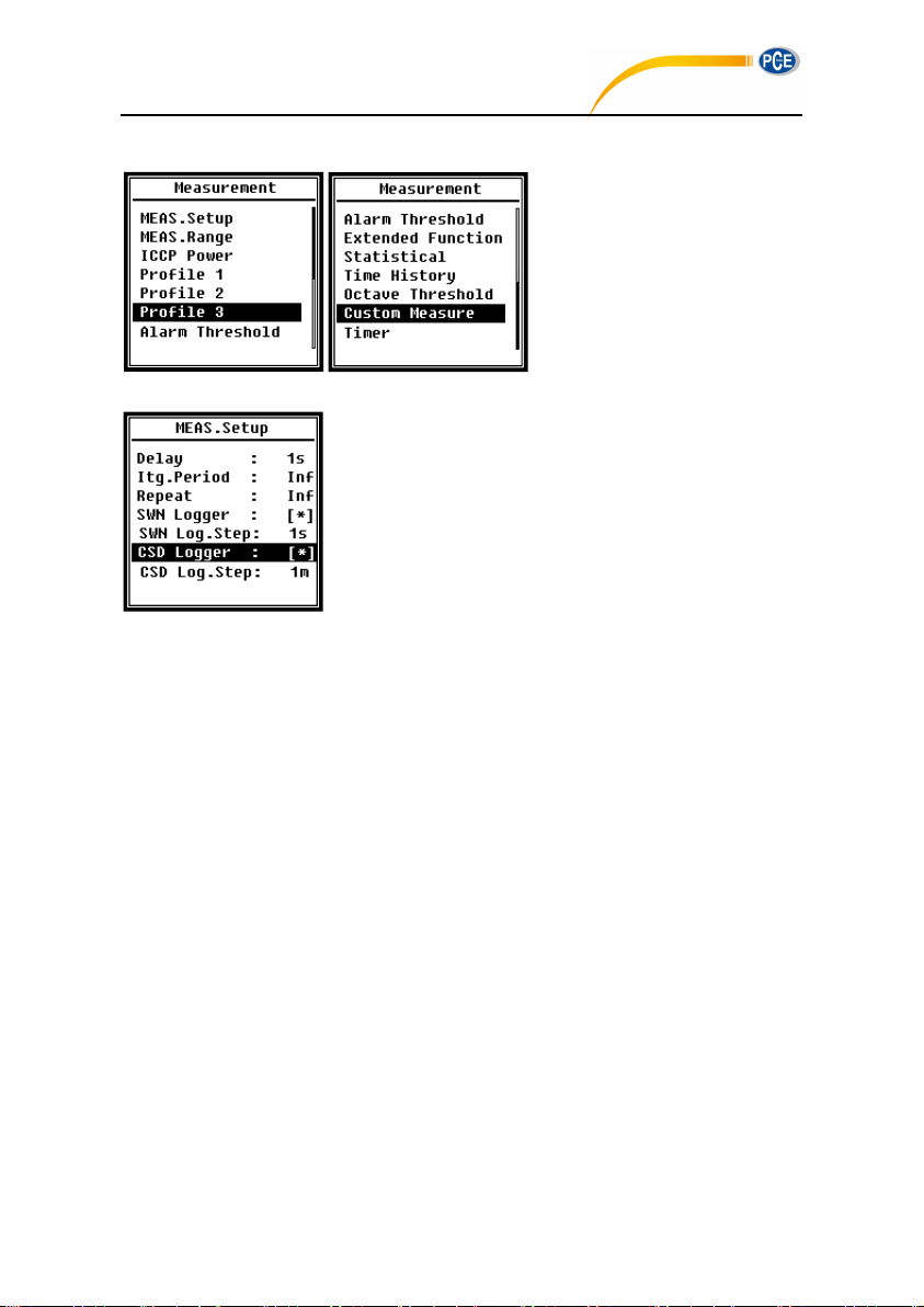
There are 13 items in the menu of
Measurement. Press <▲>, <▼>
can choose and select, press
<Enter> to access next level of
menu.
4.3.1 MEAS.Setup
Menu of MEAS.Setup is the most important menu related to
measurement. It can set the parameter of Delay, Itg.Period,
Repeat, SWN Logger, SWN Log.Step, CSD Logger and
CSD Log.Step. Press <▲>, <▼> can choose and select.
Delay:
Delay time between press <Start> and the beginning of the measurement. Press <◄>,
<►> can select the delay time: Sync 1m, Sync 15m, Sync 30m, Sync 1h, 1s~60s.
The delay time can skip the impact come from the key pressing or vibration before the
measurement.
Itg.Period:
Itg.Period is the integral period of each single measurement. At the beginning of each
integral period, all of the integral data and time-hold data will be reset, and the overload
and under-range indicator will be clear. Integral data and time-hold data include LEQ,
Max, Min, Peak, SD, SEL, E and LN. Press <◄>, <►> can select the option: Inf, 1s~59s,
1m~59m, 1h~24h.
Repeat:
Repeat is the number of repeat time of measurement. Total measurement period
=Itg.Period x Repeat. Press <◄>, <►> can select the option: Inf, 1~9999.
SWN Logger:
Press <◄>,<►> to switch. If selected, sound level meter will save the SWN/OCT files.
36
Page 33
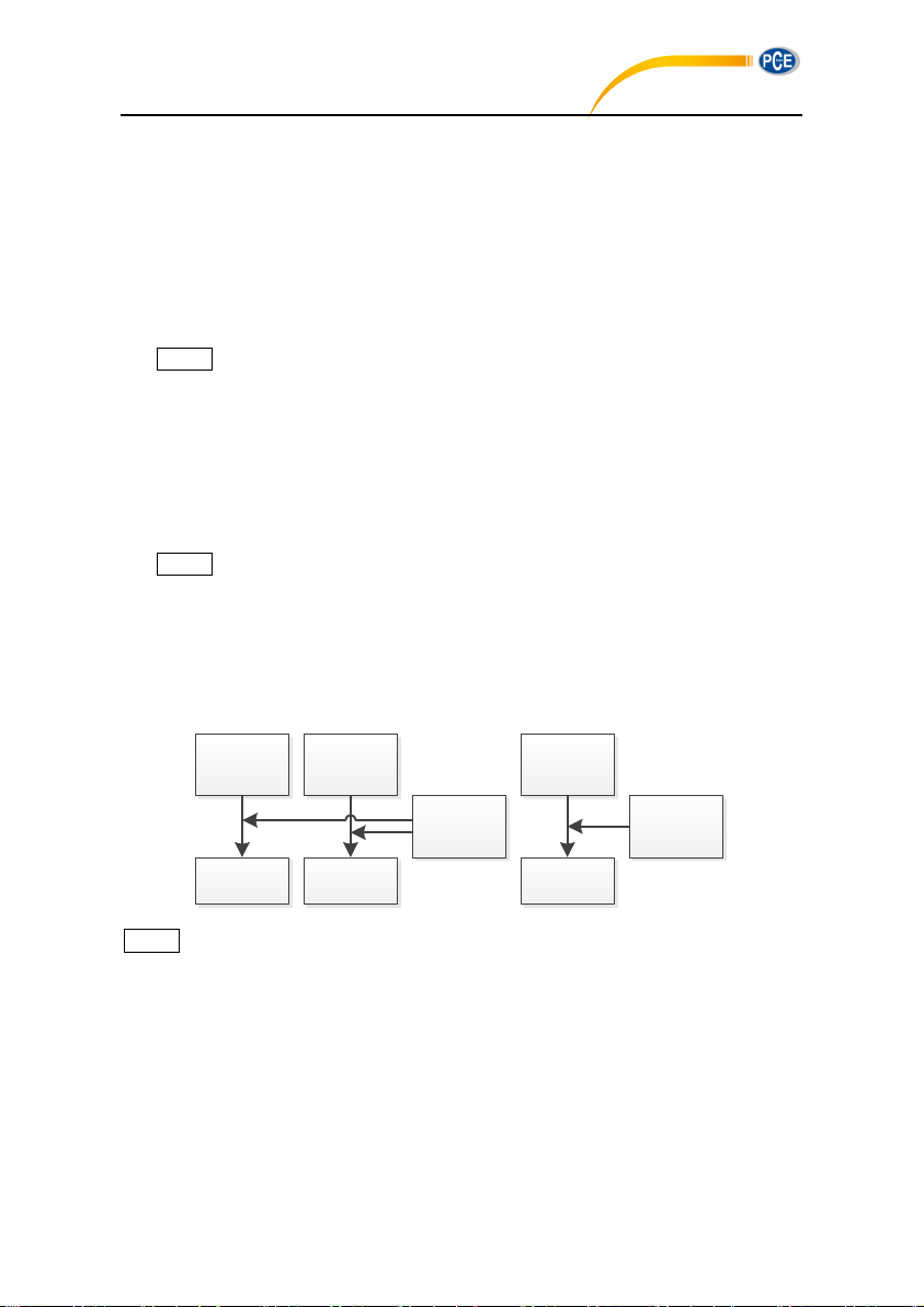
SWN/OCT saves the time history data into file. The data source in Level Meter mode is
Profile1
Profile2
Profile3
SWN File
14 sets of
Custom
Measure
CSD File
CSD
Log.Step:
1s~24h
Octave
Data
OCT File
SWN/OCT
Log.Step:
0.1s~24h
PCE-428 / 430 / 432
Profile 1~3 (select in SWN Save of Profile 1~3 menu) and store as SWN file; in 1/1
Octave mode save all bands of octave and LAeq, LBeq, LCeq, LZeq, store as OCT file.
SWN Log.Step:
SWN Log.Step is the logger step (interval time) to save data as SWN/OCT file. Press
<◄>, <►> can select the option: 0.1s, 0.2s, 0.5s, 1s~59s, 1m~59m, 1h~24h.
☆Note: The SWN Log.Step of 1/3 Octave starts from 0.5s (0.1s and 0.2s are disable).
CSD Logger:
Press <◄>,<►> to switch. If selected, sound level meter will save the CSD files.
CSD save the instantaneous data into file. The data source in Level Meter mode is 14
group results of Custom Measure and store as CSD file; in 1/1 Octave mode save all
bands of octave and LAeq, LBeq, LCeq, LZeq, store as CSD file.
☆Note: If selected, press <Enter> at the main screen can save the data into CSD file
manually when measurement is stop.
CSD Log.Step:
CSD Log.Step is the logger step (interval time) to save data as CSD file. Press <◄>,
<►> can select the option: 1s~59s, 1m~59m, 1h~24h.
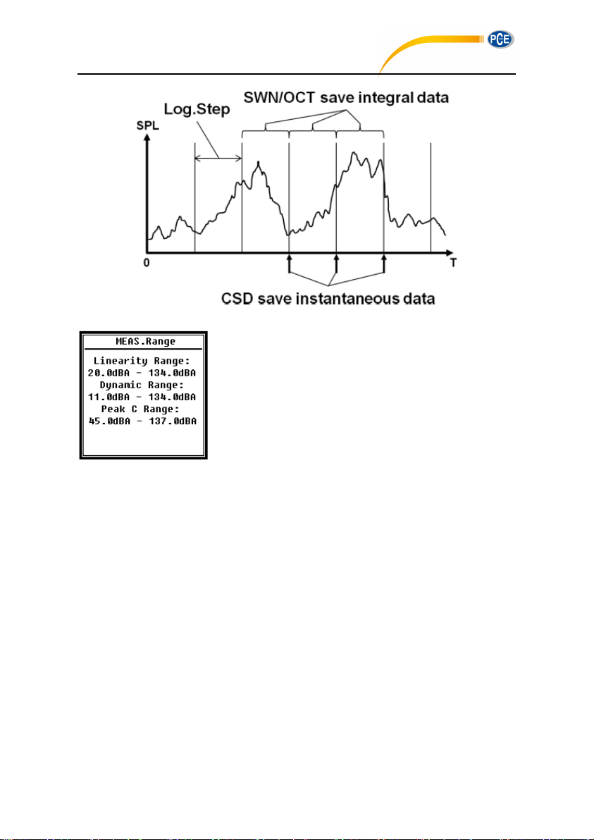
☆Note: SWN/OCT file only store integral data. The logger step can be considered as the
integral period. All the data within logger step (integral period) will be store as one line into
SWN/OCT file. CSD file only store instantaneous data without integration. Once the CSD
logger step is reached, 14 group data of custom measure will be store as one line into CSD
file, just as a screenshot.
37
Page 34
PCE-428 / 430 / 432
4.3.2 MEAS.Range
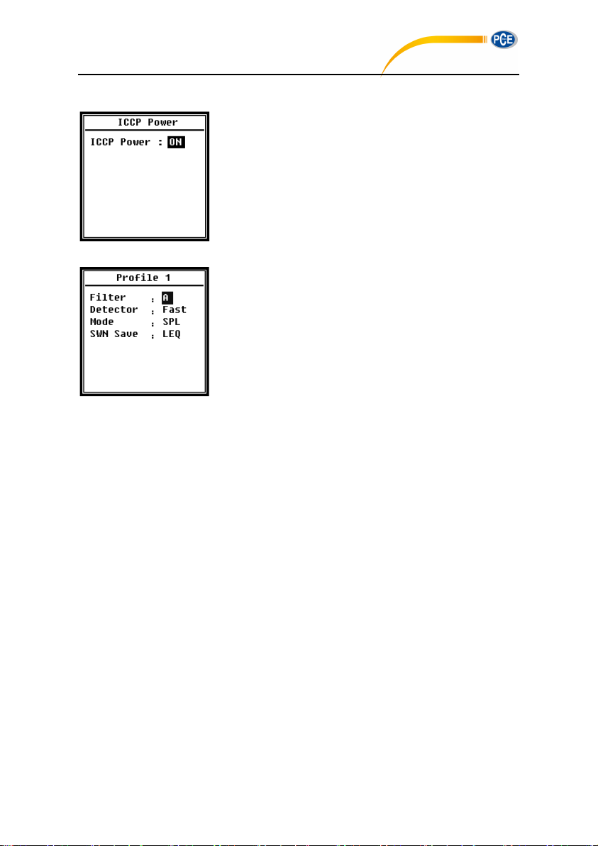
Menu of MEAS.Range display the Linearity Range, Dynamic
Range and Peak C Range.
The new developed algorithm brings a single measurement
range that no needs to change the range anymore. The
algorithm can meet the requirement of toneburst response
down to 0.25ms with only 0.1dB error at 4kHz. And the error is
0.4dB for 0.125ms toneburst test at 4kHz.
Linearity Range: The measurement result can be considered to be correct only when the
result located in the linearity range. Otherwise, the error of measurement result is over the
acceptance limits. Sometimes linearity range also can be called measurement range.
Dynamic Range: Dynamic range is the range between the self-generated noise level and
the maximum input signal level. Dynamic range is the maximum range which can be display
on the sound level meter. Note the measurement result near the self-generated noise level
can be considered is non-linear.
Peak C Range: Peak C range is the linearity range of Peak C measurement. The Peak C
measurement result located in this range can be considered to be correct.
38
Page 35
4.3.3 ICCP Power
PCE-428 / 430 / 432
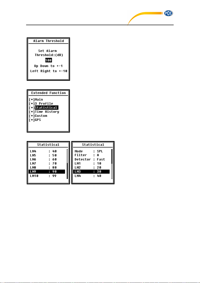
Menu of ICCP power control the 4mA/24V constant current
source which can supply all kind of ICCP sensor. Please
disable ICCP power before connect to other kind of sensor or
directly connect to signal source. Press <◄>, <►> can choose
and select.
4.3.4 Profile 1~3
Menu of Profile 1~3 can set the Filter, Detector, Mode and
SWN Save. Press <▲>, <▼> can choose and select.
Filter:
Set the filter of Profile 1~3. Press <◄>, <►> can select the option: A, B, C and Z
(Z-weighting means no weighting and sometimes it is called Flat or Linear).
Detector:
Set the detector of Profile 1~3. Press <◄>, <►> can select the option: Fast, Slow, and
Imp..
Mode:
Set the integral mode of Profile 1~3. Press <◄>, <►> can select the option: SPL, PEAK,
LEQ, MAX and MIN.
SWN Save:
This option is used to set which data should be store in the SWN file, since the data
source of SWN file is Profile 1~3. So this option is no relationship with screen display.
Press <◄>, <►> can select the option: LEQ, PEAK, MAX or MIN.
39
Page 36
4.3.5 Alarm Threshold
PCE-428 / 430 / 432
If measurement result of Profile 1~3 exceeds the Alarm
Threshold, the LED indicator above <Power> will turn red.
Alarm threshold can be set to 20dB~200dB. Press <▲>, <▼>
can increase and reduce 1dB. Press <◄>, <►> can add and
reduce 10dB.
4.3.6 Extended Function
Extended Function can set which screen can be display. If the
screen is not selected, it will not be display. Note that Main
screen is designed to be displayed all the time.
4.3.7 Statistical
The data source of statistical is
SPL which is fixed. User can’t
change it. But user can set the
filter and detector of SPL and the
statistical percentage value
through this menu.
Mode:
It’s fixed to SPL and cannot be changed.
Filter:
Press <◄>, <►> can set the filter of statistical analysis: A, B, C and Z (Flat).
Detector:
Press <◄>, <►> can set the detector of statistical analysis: Fast, Slow and Imp..
LN1~LN10:
Press <◄>, <►> can set the percentage of 10 group of LN to 1%~99%.
For example: LN1:10=80dB means that in integral period, 10% of measurement data is
40
Page 37
greater than 80dB. The LN result related to integral period. It will be reset when a new
PCE-428 / 430 / 432
integral period start.
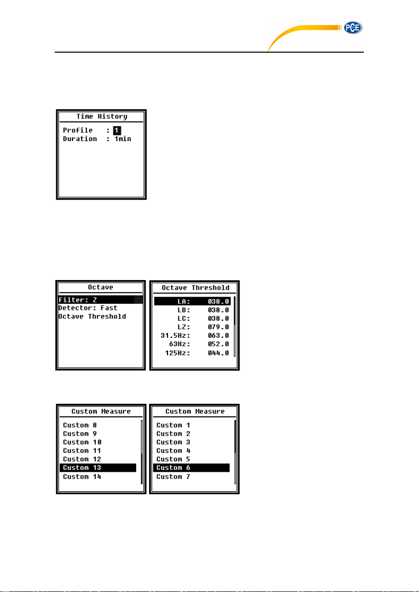
4.3.8 Time History
Press <▲>, <▼> can set the data source and duration time of
Time History.
Profile:
Press <◄>, <►> can set the data source of time history: Profile1, Profile 2, Profile 3.
Duration:
Press <◄>, <►> can set the timeline of time history: 1min, 2min, 10min.
4.3.9 Octave
Menu of Octave can set filter and
detector before octave calculation
and the alarm threshold of each
octave band, LA, LB, LC, LZ. If
the measurement result exceeds
the threshold, the LED indicator
will turn red. Press <◄>, <►> can set the option to 0.1dB~199.9dB.
4.3.10 Custom Measure
There are 14 items in menu of
Custom Measure which can set
the parameters of group 1~14
custom measurement. Press <▲>,
< ▼ > can choose and select,
press <Enter> to access next
level of menu.
41
Page 38
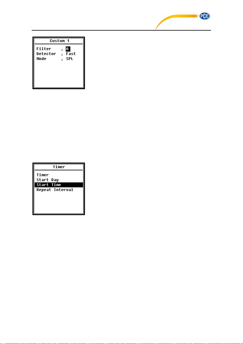
Press <▲>, <▼> can set the option of each group of custom
PCE-428 / 430 / 432
measurement: Filter, Detector and Mode.
Filter:
Press <◄>, <►> can set the filter of custom measurement: A, B, C and Z (Flat).
Detector:
Press <◄>, <►> can set the detector of custom measurement: Fast, Slow and Imp..
Mode:
Press <◄>, <►> can set the integral mode of custom measurement: SPL, SD, SEL, E,
Max, Min, Peak, LEQ, LN1~LN10.
4.3.11 Timer
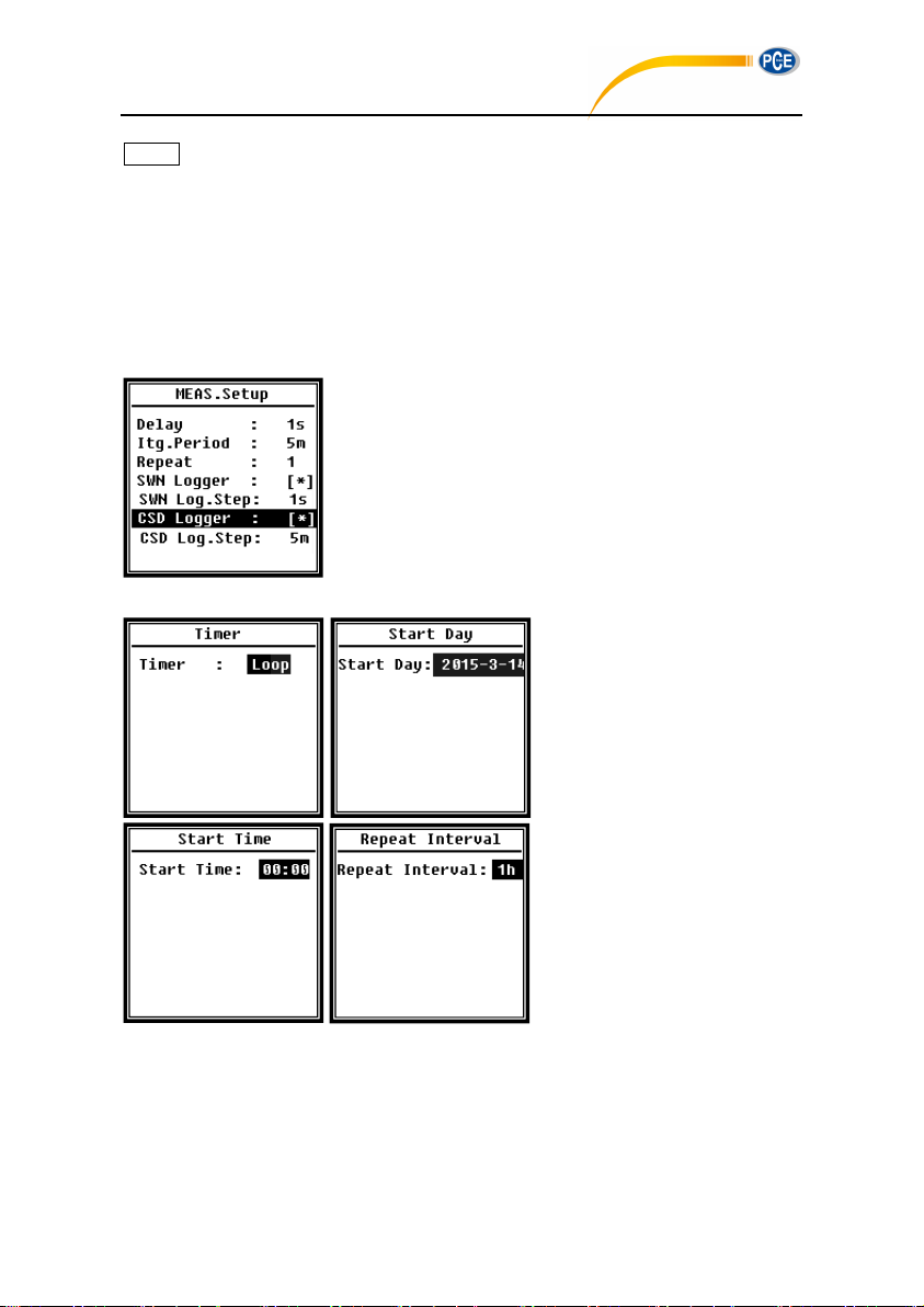
Menu of Timer can set the Timer, Start Day, Start Time and
Repeat Interval. Press <▲>, <▼> can choose and select.
A new function named Timer was introduced to start
measurement by program. User can set the measurement
start from 00:00 of next day, measure several minutes and
repeat each hour, in order to achieve 24h auto measurement.
Timer:
Press <▲>, <▼> can set Timer working mode: OFF, Once and Loop.
Start Day:
Press <▲>, <▼> can set Timer trigger date: Ignore and the certain day in the future 30
days. If select Ignore, the Timer will ignore the date and only use Start Time to trigger.
Start Time:
Press <▲>, <▼> can set Timer trigger time: 00:00~23:59.
Repeat Period:
If Timer is triggered, it will be trigger all the time by the Repeat Period. Press <◄>, <►>
can set the option: 1m~59m, 1h~24h.
42
Page 39
☆Note: Repeat Period must greater than total integral time (Itg.Period x Repeat) +5s,
PCE-428 / 430 / 432
since there is fixed 3s delay for Timer triggered measurement and another 2s is needed
before the delay. It is forbidden to change the settings when the Timer is working. Otherwise,
there will be something wrong with the Timer.
4.3.12 24h Measurement by Timer
User can use the Timer to implement 24-hour-measurement. Following description show an
example of how to implement the 24-hour -measurement.
Purpose: The measurement will be first start at 2015/3/14
00:00, measure first 5m of each hour. It will store CSD file
when the stop measurement and store SWN file every second.
Delay setting in the MEAS.Setup will be ignored if the
measurement is triggered by Timer. Set Itg.Period as 5m and
set Repeat as 1. Enable the SWN Logger and CSD Logger.
Set the SWN Log.Step to 1s and set the CSD Log.Step to 5min.
Set the Timer work at Loop mode,
so that the measurement will be
triggering all the time.
Set the Start Day as the wanted
date.
Set the Start Time to 00:00 which
means the first time of
measurement to be triggered.
Set the Repeat Interval to 1h, so
that the measurement will be
triggering each hour.
43
Page 40
4.4 Setup
PCE-428 / 430 / 432
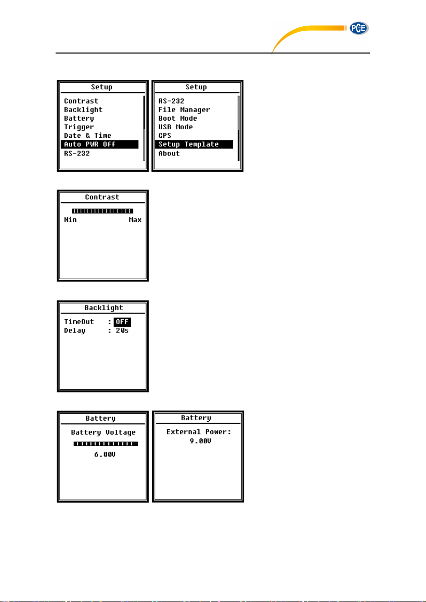
Menu of Setup include the basic
function setup and condition
display. Press <▲>, <▼> can
choose and select, press <Enter>
to access next level menu.
4.4.1 Contrast
Menu of Contrast can set the contrast of LCD display for 14
levels adjustable. Press <▲>, <▼> can choose and select.
4.4.2 Backlight
Sound level meter provide the auto turn off function of
backlight to reduce the power consume and extend battery life.
Menu of Backlight can set the backlight timeout on-off and
delay time. Press <▲>, <▼> can choose and select.
4.4.3 Battery
Menu of Battery display the
power state and power voltage.
The discharge cut-off voltage of
single cell LR6/AA/AM3 alkaline
battery is approx. 0.9V, therefore
sound level meter will power off
automatically when the total voltage of 4 cell alkaline battery falls below 3.6V.
44
Page 41
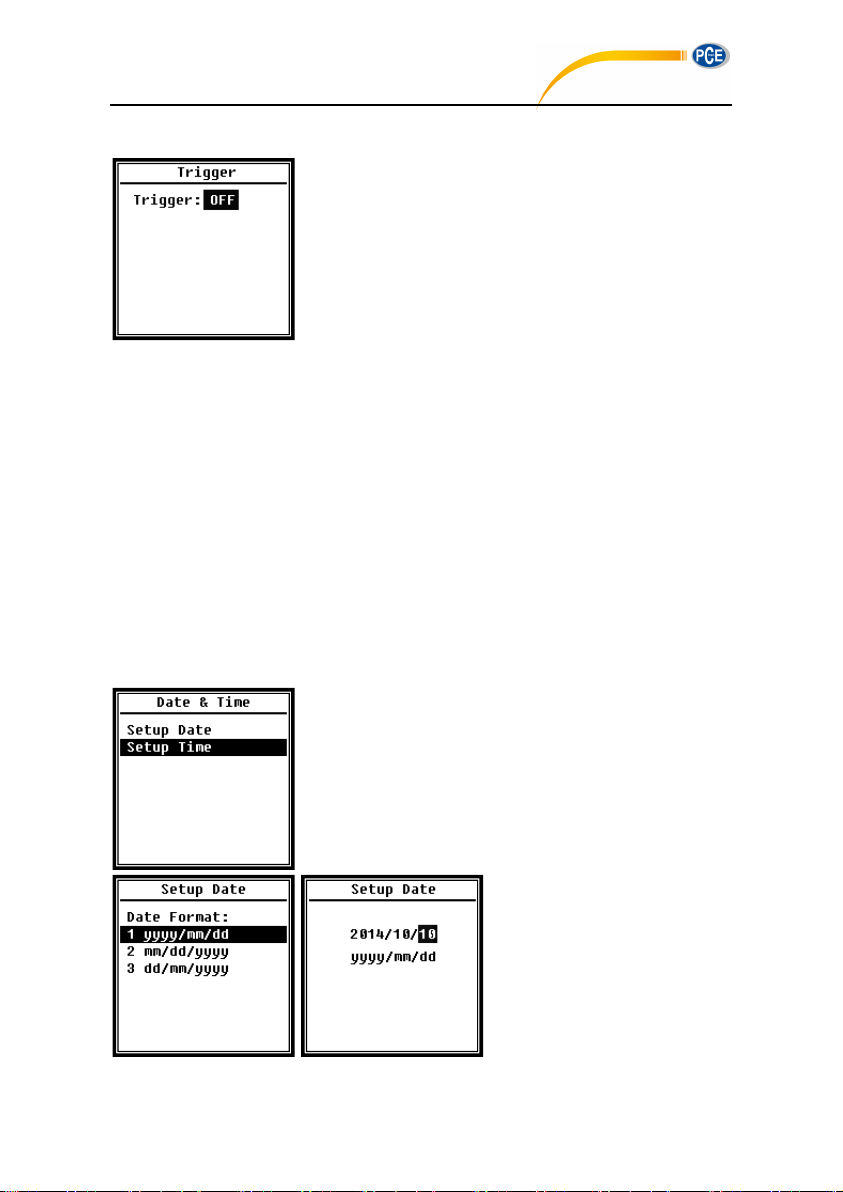
4.4.4 Trigger
PCE-428 / 430 / 432
Menu of Trigger can set the function of trigger on-off. Trigger
is an analog input which remote control the sound level meter
to start or stop the measurement. The trigger input located on
the bottom of sound level meter as a 3.5mm connector.
Short the signal lines and ground to trigger measurement to start, otherwise to stop the
measurement. Notice that when enable the Trigger function, the <Start/Stop> button is
unavailable.
4.4.5 Date & Time
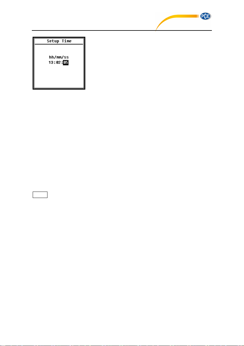
Menu of Date & Time can set the RTC time of sound level
meter. Press <▲>, <▼> can choose and select.
Press <▲>, <▼> can select date
format and turn to date setting.
Press <◄>, <►> can choose
year, month and day, press <▲>,
<▼> can modify the value. Press
<Enter> to save the setting.
45
Page 42
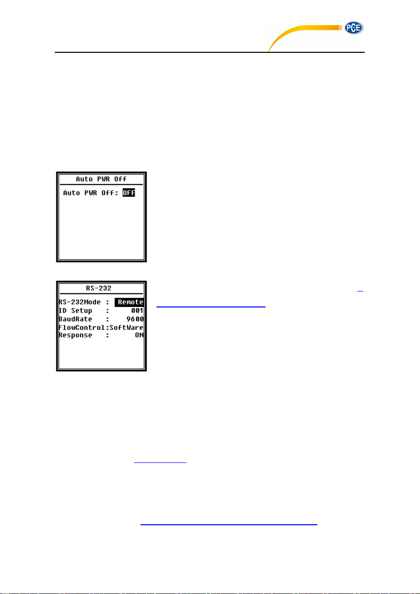
The operation of time setting is almost the same. Press <◄>,
PCE-428 / 430 / 432
<►> can select hour, minute and second, press <▲>, <▼>
can modify the value. Press <Enter> to save the setting.
The power supply for RTC comes from an internal battery.
Please replace the RTC battery when sound level meter
cannot keep the date and time due to voltage of RTC battery is
too low. How to replace RTC battery: remove the 5 screws on the backside of sound level
meter to open the cover. The RTC battery is located on the surface of PCB as the following
figure. The model of battery is CR-1220.
☆Note: The RTC of sound level meter has calibrated to a reference clock with average error
2ppm (maximum error 3ppm). The time accuracy keep <10ppm (<26s within 30 days) at
room temperature. The maximum time error is approx. 5s~8s at 25℃ in internal test.
The RTC accuracy may vary by the
temperature due to no temperature
compensation. As the figure show the
typical temperature curve, the RTC
keep its basic frequency at 25 ℃ .
When the temperature increase or
decrease, RTC frequency change
according to -0.04ppm/℃2. Therefore,
when the temperature is 0 ℃ , the
change value of RTC is -0.04 x (0-25)2
46
Page 43
= -25ppm, equal to slow 2.16s daily. when the temperature is 40℃, the change value of RTC
PCE-428 / 430 / 432
is -0.04 x (40-25)2 = -9ppm, equal to slow 0.78s daily.
The maximum error (<10ppm) given by user manual can be calculated as approx. 16℃
difference to reference temperature (25℃). Therefore, the RTC can keep every 30 day the
error <26s at 9℃~41℃ which can be recognized as room temperature. Notice that the real
RTC error may beyond the value shown in user manual if exceed the temperature range.
4.4.6 Auto PWR Off
Sound level meter provide the auto power off function to
reduce the power consume. When sound level meter keep
stop state and no key press for a while, it will power off base on
the setting. The Auto PWR Off option: 1min, 5min, 10min,
30min, Off. Press <◄>, <►> can choose and select, press
<Enter> to save the setting.
4.4.7 RS-232
Menu of RS-232 can set the option of serial port, refer to 5.
RS-232 Communication Protocol to earn more detail.
RS-232 Mode:
RS-232 Mode option:Remote, Printer. Press <◄>, <►> can choose. Sound level
meter can be control and send out data via RS-232 port at Remote mode. And RS-232
can be used to connect thermal printer (option) at Printer mode.
ID Setup:
ID Setup (refer to 5.2.2 Device ID to earn more detail) can set the ID number which is
used to distinguish among a network of more than one sound level meter. The ID can be
set as: 1~255. Press <◄>, <►> can choose and select.
Baud Rate:
Baud Rate (refer to 5.1 Hardware Configuration and Settings of Interface to earn more
47
Page 44
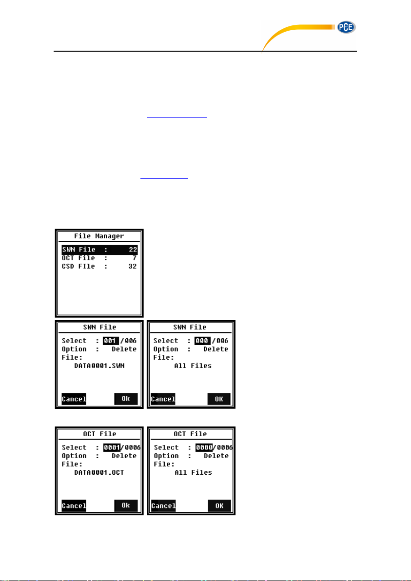
detail) can set the communication baud rate of RS-232, the option is: 4800bps, 9600bps,
PCE-428 / 430 / 432
19200bps. Press <◄>, <►> can choose and select.
Flow Control:
Flow Control (refer to 5.2.7 Flow Control to earn more detail) can set the flow control
mode under remote control, the option is: Software, Hardware. Press <◄>, <►> can
choose and select.
Response:
Response (refer to 5.3 Instruction to earn more detail) can enable or disable the
response signal (ACK/NAK), the option is: ON, OFF. Press <◄>, <►> can choose and
select.
4.4.8 File Manager
File Manager can manage the stored SWN, OCT and CSD file.
The numbers display at the right side of each line is the file
count for each kind of file type. Press <▲>, <▼> can choose
and select, press <Enter> to access next level of menu.
Menu of SWN File can delate
SWN files, press <▲>, <▼> to
select the file number which want
to be delete. The whole file name
will be display on the bottom of
the screen. Select 0000 as the file
number can delete the entire existing SWN file.
Menu of OCT File can delete the
OCT file. The operation is same to
menu of SWN File.
48
Page 45
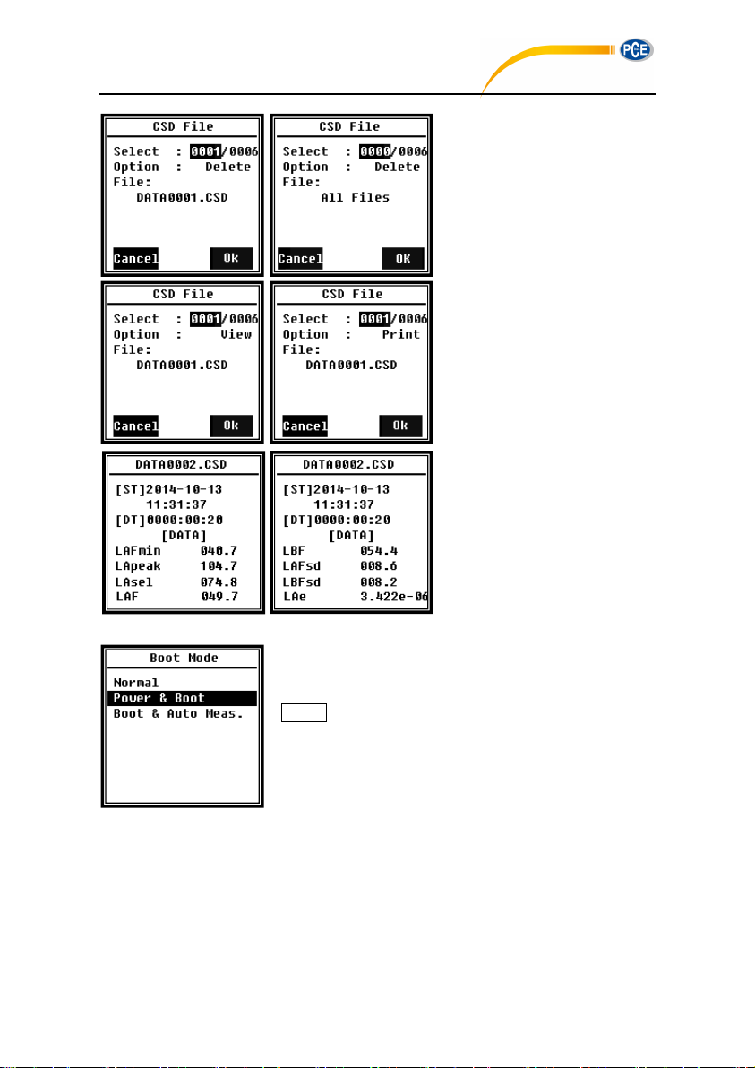
Menu of CSD File can view, print
PCE-428 / 430 / 432
and delete the CSD file. Press
<▲>, <▼> can change the cursor
between Select and Option.
Delete operation is same to menu
of SWN File.
Select Option in menu of CSD
File, and then press <◄>、<►>
can View or Print the CSD file.
After select file number and action,
press <Enter> to view or print the
content of file.
Press <▲>, <▼>, <◄>, <►> can
brown file contents at View mode.
The Print mode is almost same to
View mode. Press <Enter> can
print the current displayed content
of CSD file.
4.4.9 Boot Mode
In menu of Boot Mode, press<▲>, <▼> can select Normal,
Power & Boot, Boot & Auto Meas. mode.
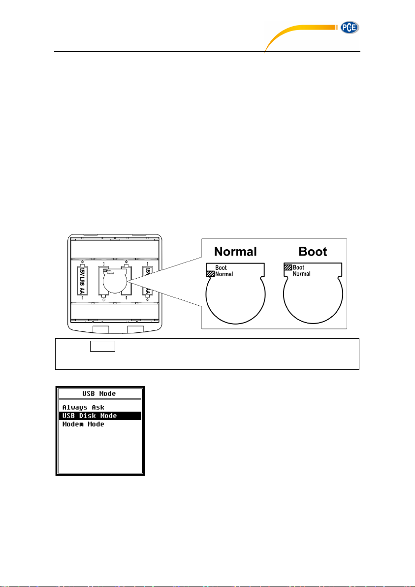
☆Note: The hardware mode switch located in the battery
compartment need to be set to fit to different boot mode.
Normal:
Need to change hardware mode switch to Normal. This is the normal working mode of
sound level meter.
Power & Boot:
Need to change hardware mode switch to Boot. After select this mode, sound level
49
Page 46
meter will power on when proper power supply available. It’s suitable for integrate into
☆Note: Static electricity sensitive area. Eliminate static electricity before
operation.
PCE-428 / 430 / 432
other system, especially in those cases where power failure, sound level meter can
power on automatically from power shutdown.
Boot & Auto Meas.:
Need to change hardware mode switch to Boot. After select this mode, sound level
meter will not only power on when proper power supply available, but also start
measurement. When sound level meter was integrated into other system, it will power on
and start measurement automatically from power failure.
Hardware Mode Switch:
The hardware mode switch located in the battery compartment. It’s easily to be found
after remove the batteries. Please select the switch to Boot or Normal by nib or tweezers.
4.4.10 USB Mode
Menu of USB Mode can set the working mode when connect
sound level meter to computer by USB cable. Always Ask,
USB Disk Mode and Modem Mode can be select.
Always Ask:
It always ask which mode should apply when connect to computer by USB. Please make
choose in time, otherwise computer could not recognize the sound level meter due to
50
Page 47
timeout.
PCE-428 / 430 / 432
USB Disk Mode:
It always working at USB Disk Mode without ask when connect to computer by USB.
Sound level meter can be recognized as removable USB disk by computer without driver
install, and the files stored in MicroSD card can be access by explorer directly.
Modem Mode:
It always working at Modem Mode without ask when connect to computer by USB.
Sound level meter can be recognized as serial port (virtual serial port) by computer and
follow the same protocol as RS-232 (refer to 5. RS-232 Communication Protocol to earn
more detail of protocol).
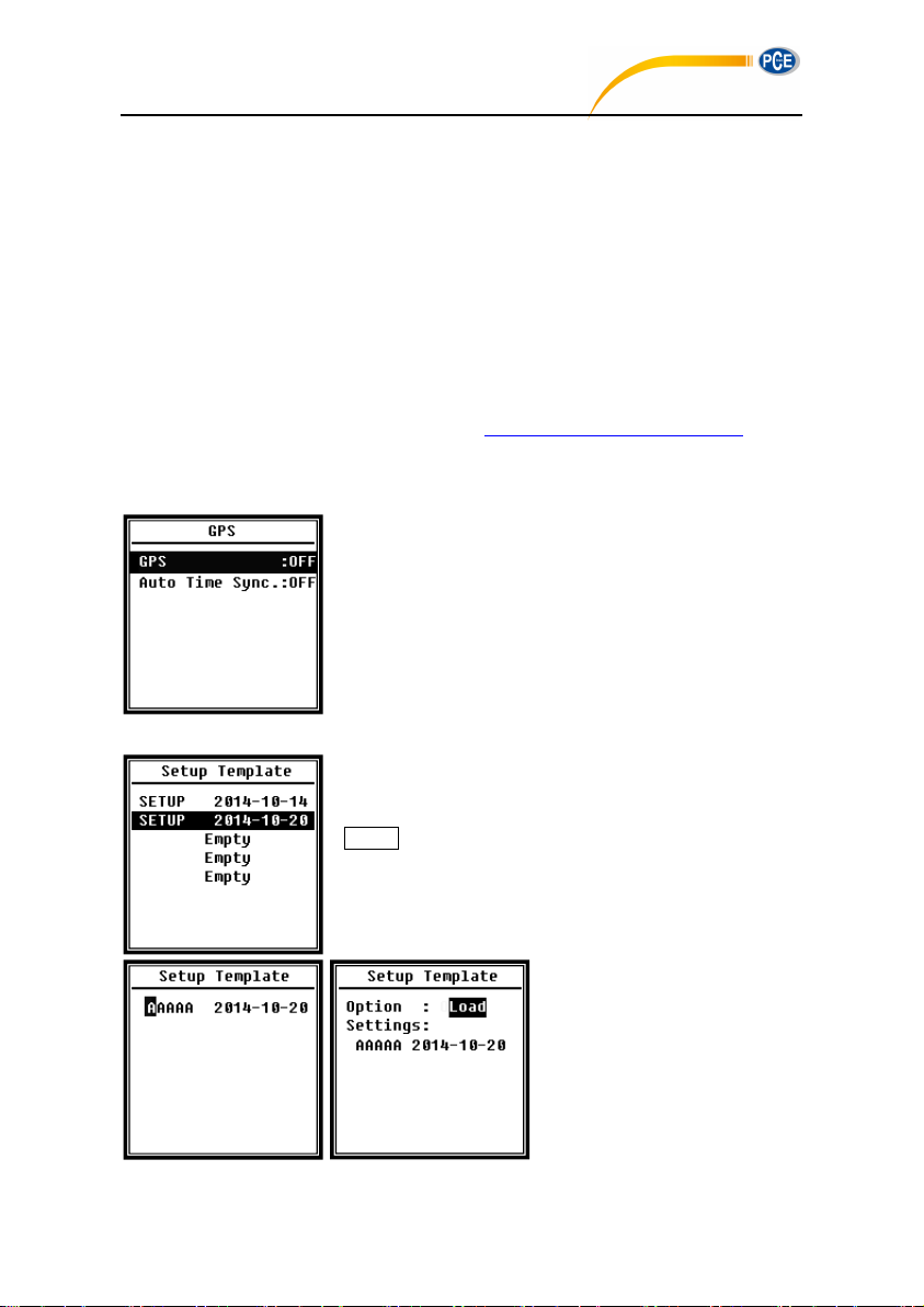
4.4.11 GPS
Menu of GPS can set the GPS and Auto Time Sync on-off.
When GPS is turn off, the internal GPS module is shutdown. If
enable Auto Time Sync, the RTC of sound level meter will be
synchronized when get GPS time and then keep
synchronization once per hour.
4.4.12 Setup Template
The Setup Template is used to store 5 group user setting
parameter of sound level meter for different application.
☆Note: Template will not touch the Cal.Factor. Please do not
try to load the old version template in new version firmware
due to some modification could be apply in template format.
Press <Enter> on blank template
can save 1 group setting which
user can define the name by 5
letter or number.
Press <Enter> on one existing
template can load or delete it.
51
Page 48
4.4.13 About
PCE-428 / 430 / 432
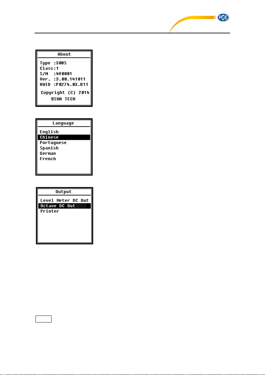
About menu shows the Type, Class, S/N (serial number), Ver.,
and HWID (hardware ID) of sound level meter.
4.5 Language
Sound level meter support 6 language: English, Chinese,
Portuguese, Spanish, German and French. Press <▲>, <▼>
can select appropriate language and press <Enter> to save
the setting.
4.6 Output
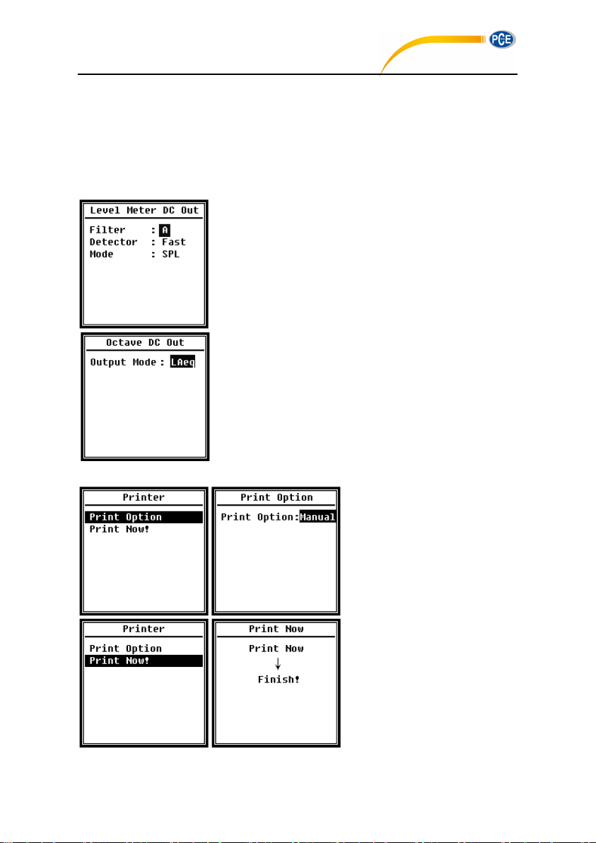
Menu of Output can select which measurement data should
be output at DC OUT. There are Level Meter DC Out and
Octave DC Out option for level meter mode and 1/1 octave
mode. The Printer option also be include in this menu. Press
<▲>, <▼> can choose and select.
4.6.1 AC OUT
There are two analog output ports on sound level meter: DC OUT and AC OUT. Please use
coaxial cable to connect DC OUT, AC OUT to other device or system. Recommend input
resistance of terminal device or system should above 5kΩ.
AC OUT port is located on the bottom of sound level meter. It output the signal of microphone
directly without and setting can be apply. The maximum output voltage is 5Vrms (±7Vpeak),
and maximum output current is ±15mA.
☆Note: Please add impedance transformation circuit when input resistance of terminal
device or system is not so high enough. AC OUT is only can be used for noise recording or
52
Page 49
monitor due to noise floor is higher than the lower limit of linear range of sound level meter.
PCE-428 / 430 / 432
4.6.2 DC OUT
DC OUT is used to output the analog DC signal which is proportional to measurement result
with 10mV/dB ratio. For example, it output 938mV for 93.8dB. Recommend to filter or
average the output signal to remove noise.
Level Meter DC Out can set the signal output of level meter
mode. Press <▲>, <▼>, <◄>, <►> can choose and select.
Filter: A, B, C, Z (Flat)
Detector: Fast, Slow, Imp.
Mode: SPL, LEQ, Peak
Octave DC Out can set the signal output of octave mode. The
option is: LAeq, LBeq, LCeq, LZeq and 6.3Hz~20kHz. Press
<◄>, <►> can choose and select. If select unavailable band
for current function, it will display “Invalid Octave Band!”.
4.6.3 Printer
Print Option can set the printer
option to Auto or Manual. Select
Auto will print measurement result
automatically after stopped
measurement.
If user selects Manual option,
select Print Now and press
<Enter> to print measurement
data.
53
Page 50
☆Note: Please set to Printer mode in RS-232 menu before print operation.
PCE-428 / 430 / 432
4.7 Factory Settings
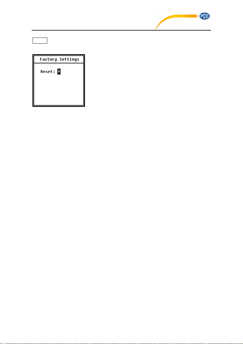
Factory Settings provides the function for reset all the
parameters which has been modify by users. The parameters
will be initialized to the default value. Press <◄>, <►> can
select Y (Yes) or N (No). Choose Y and pressing <Enter> will
initialize the parameter. Choose N or press <ESC> will cancel
the reset.
54
Page 51
5. RS-232 Communication Protocol
Transfer Mode
Full-duplex
Synchronous / Asynchronous Mode
Asynchronous transfer
Baudrate
4800 bps, 9600 bps, 19200 bps
Data Bits
8 bit
Stop Bits
1 bit
Parity
None
Flow Control
Follow the time data in the rated parameters table
Send command block
Send response block
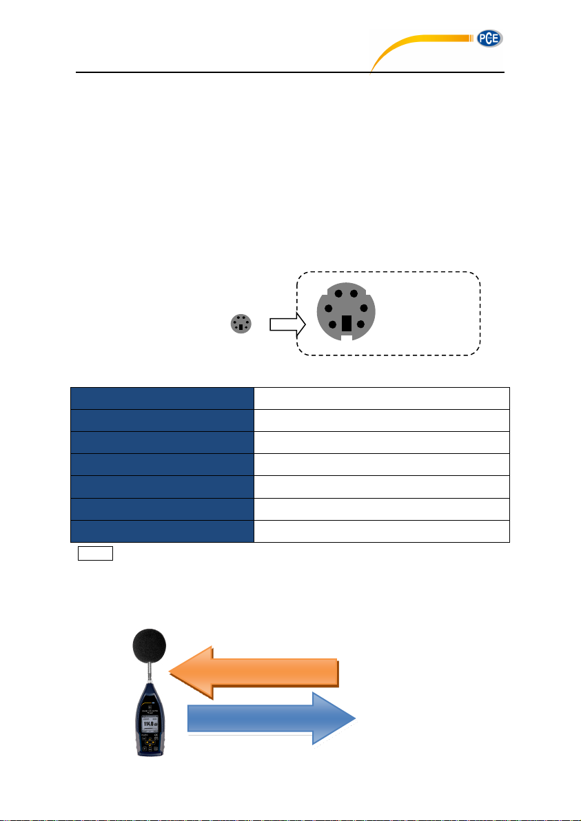
1. NC
6. RXD
3 2 1 4 5
6
PCE-428 / 430 / 432
The Sound Level Meter 3&( has an RS-232 serial interface. User can modify the
configuration of the sound level meter via a serial interface and control the sound level meter
to run and to stop, and get the current measurement parameters and results for further
processing. Operation via serial interface does not affect keyboard operation.
5.1 Hardware Configuration and Settings of Interface
3&( uses three-wire serial interface, the physical socket is PS/2-6 pins. Below is
the definition of RS-232 interface:
RS-232 transfer settings:
2. GND
3. NC
4. TXD
5. NC
☆Note: RS-232 connector housing should be grounded and recommended to use ground
shield wire. Please be sure to use quality and reliable RS-232 to RS-485 adaptor.
5.2 Transfer Protocol
3&( RS-232 interface protocol is based on a block transfer, as shown below:
55
Page 52
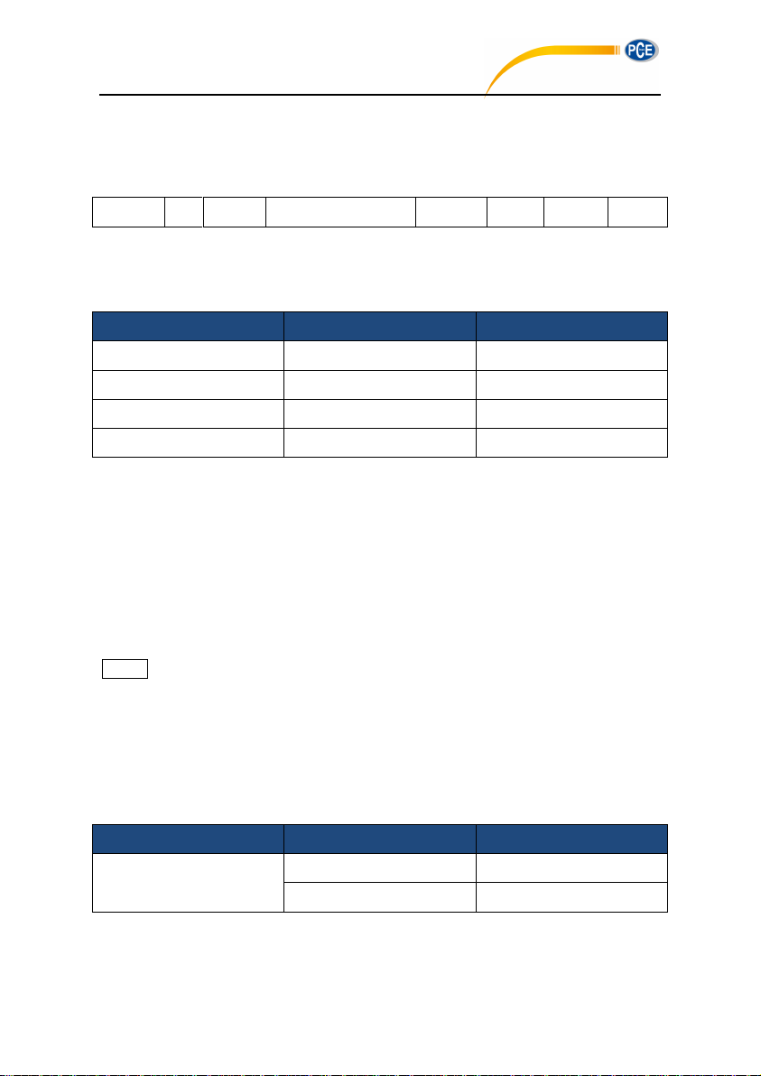
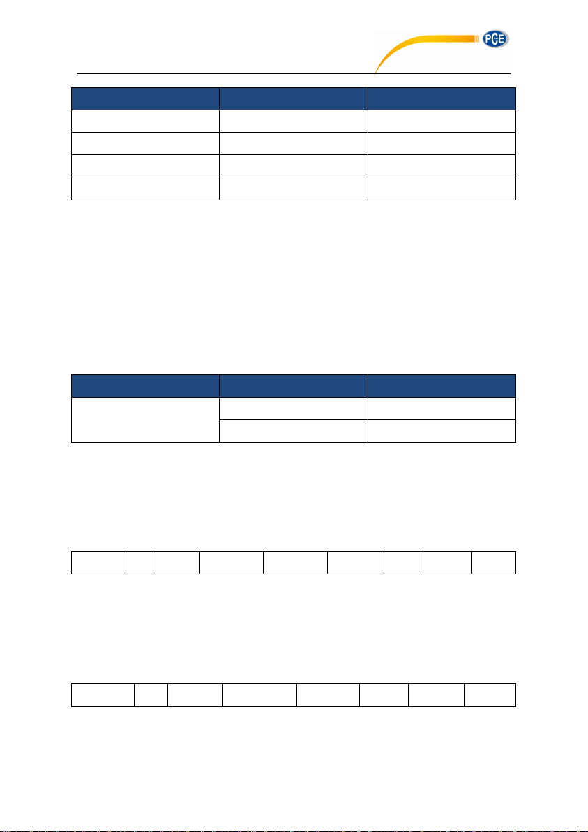
A typical command block or response block consists of “starting character, ID, attribute
<STX>
ID
ATTR
Command or Data
<ETX>
BCC
<CR>
<LF>
Name
Hex
Meaning
<STX>
02H
Start Character
<ETX>
03H
Stop Character
<CR>
0DH
Carriage Returns
<LF>
0AH
Line Feeds
Name
Hex
Meaning
ID
01H~FFH
Device ID
00H
Broadcast Command
PCE-428 / 430 / 432
character, command or data, end character, block check character, carriage returns, line
feeds”, as shown below:
5.2.1 Start/Stop of the Block Transfer
A command block or response block contains start characters, end characters and other
control character as shown below:
5.2.2 Device ID
Each command block contains an ID. It is used to distinguish among a network of more than
one sound level meter. When the sound level meter receives a command block, it will match
the ID contained in the command block and its own ID. If matched, the corresponding
operation will be performed. If not, then ignore this command. The response block returned
from the sound level meter also contains the ID which is used to indicate that the block is sent
by which one.
☆Note: Please ensure that the ID of sound level meter in the same network are different
from each other, otherwise the error will occur during operation!
ID is one byte of binary. It ranges from 1~255.The corresponding hex value is 01H~FFH.
It means that the command is a broadcast command if the ID contained in command block is
00H. The sound level meter will execute the instruction without any return data, regardless of
its own ID when the command is a broadcast command.
5.2.3 ATTR Attribute Character
ATTR attribute characters indicate the type of command or response.
56
Page 53
Name
Hex
Meaning
‘C’
43H
Command Block
‘A’
41H
Response Block
<ACK>
06H
Normal Response
<NAK>
15H
Error Response
5.2.4 BCC (Block Check Character)
Name
Hex
Meaning
BCC
01H~FFH
XOR Checksum
00H
Ignore the Checksum
<STX>
ID
ATTR
Instruction
Parameter
<ETX>
BCC
<CR>
<LF> 1 1 1 3 N 1 1 1
1
<STX>
ID
ATTR
Response
<ETX>
BCC
<CR>
<LF> 1 1 1 N 1 1 1 1
Byte
Byte
PCE-428 / 430 / 432
BCC check bit which include in block is calculated by the sender. The receiver can calculate
the block’s BCC value and will compare with the BCC value contained in the send block. If
same, it indicates that the received block is correct. BCC value is calculated by using bytes
between <STX> and <ETX> with XOR operation. Sound level meter will not verify operation
and directly authorized instruction if BCC is 00H.This way you can simplify the sending of the
instruction block, but do not recommend this way for long-distance applications, because the
BCC is the only way to guarantee reliability of data transmission.
5.2.5 Block Transfer Format
Block transfer of data have four types: command block, response block, normal response
block and error response block. The following were to describe the four types of instruction
format.
(1) Command Block: sent by the computer.
Where: ATTR=’C’.
All instructions occupy 3 bytes. If more than one parameter included, all parameters should
be separated by spaces.
(2) Response Block: sent by the sound level meter.
57
Page 54
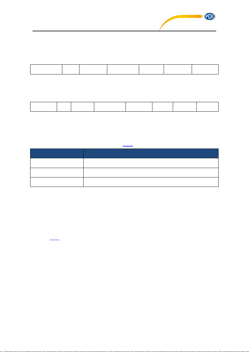
Where: ATTR=’A’.
<STX>
ID
ATTR
<ETX>
BCC
<CR>
<LF>
1 1 1 1 1 1 1
<STX>
ID
ATTR
Error code
<ETX>
BCC
<CR>
<LF> 1 1 1 4 1 1 1 1
Error Code
Meaning
0001H
Instruction Error
0002H
Parameter Error
0003H
Unavailable on the Current State
Byte
Byte
PCE-428 / 430 / 432
If more than one response data, each data should be separated by a comma ‘,’.
(3) Normal Response: sent by the sound level meter.
Where: ATTR=<ACK>。
(4) Error Response: sent by the sound level meter
Where: ATTR=<NAK>.
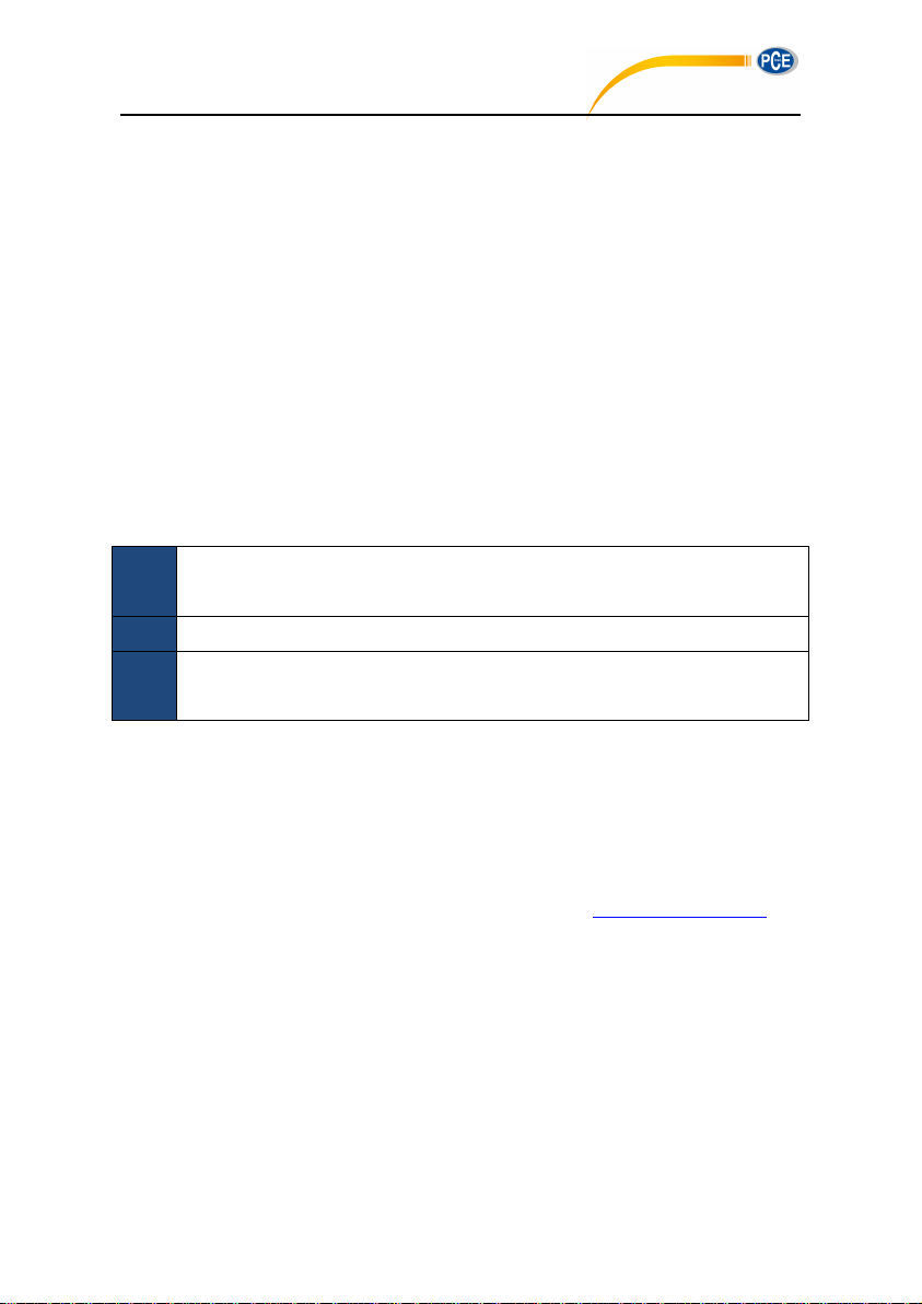
The error code occupies 4 bytes. All possible error code is listed in the following table. The
meaning of error code is described in section 5.2.6.
5.2.6 Recovery from Transmission Errors
Various errors may occur when transfer the command block or response block. The following
describe how the sound level meter will deal with and restore to the initial state when an error
occurs.
(1) Block Transfer Not Complete
Section 5.2.5 describes the 4 kinds of block transmission format. When the sound level meter
receives the beginning of a block of characters <STX>, it will continue to receive the
remaining data until the end of the block <CR>, <LF>. When the data reception is complete
and correct parity, the sound level meter will conduct follow-up actions. If received the
character <STX> again before <CR>, <LF>, the sound level meter will ignore all the
information previously received and re-start the reception of a block.
(2) Validation Failure
After receiving the data block, sound level meter will verify it (except when BCC=00H). When
validation fails, the sound level meter will ignore this instruction.
58
Page 55
(3) Instruction Error
1
Be request to return octave data in level meter mode, or be request to return level
meter data in octave mode.
2
Be request to perform the calibration operation when running the measurement.
3
Be request to change the measurement parameters or system parameters when
running the measurement.
PCE-428 / 430 / 432
The sound level meter may not recognize the instruction received due to the computer sends
an undefined instruction, or unexpected error has occurred during transmission. When the
above errors occur, the sound level meter will return a NAK block, which contains the error
code 0001H.
(4) Parameter Error
Parameters include in command block also could be wrong due to the parameters not
separate by a space, over the available range, or an incorrect number of arguments. When
the above error occurs, the sound level meter will return NAK block, which contains the
error-code 0002H.
(5) Unavailable on the Current State
The current state cannot make the appropriate operating when the following happens:
When the above error occurs, the sound level meter will return NAK block, which contains the
error-code 0003H.
5.2.7 Flow Control
The sound level meter uses three-wire serial interface by P/S2-6 pin socket, which doesn’t
contain the hardware flow control pins. Sound level meter doesn’t support software flow
control. Operation along to the requirements of the rated section 5.2.9 Rated Parameters can
guarantee the correctness of the send data and receive data.
5.2.8 Multi-Machine Operation
More than one sound level meter can be connected to the RS-232 bus, to form a
measurement network. Users can change the setting of all sound level meter in same
network through broadcast instruction, or access to data and parameters of an each sound
level meter by ordinary instruction.
Need to pay attention:
59
Page 56
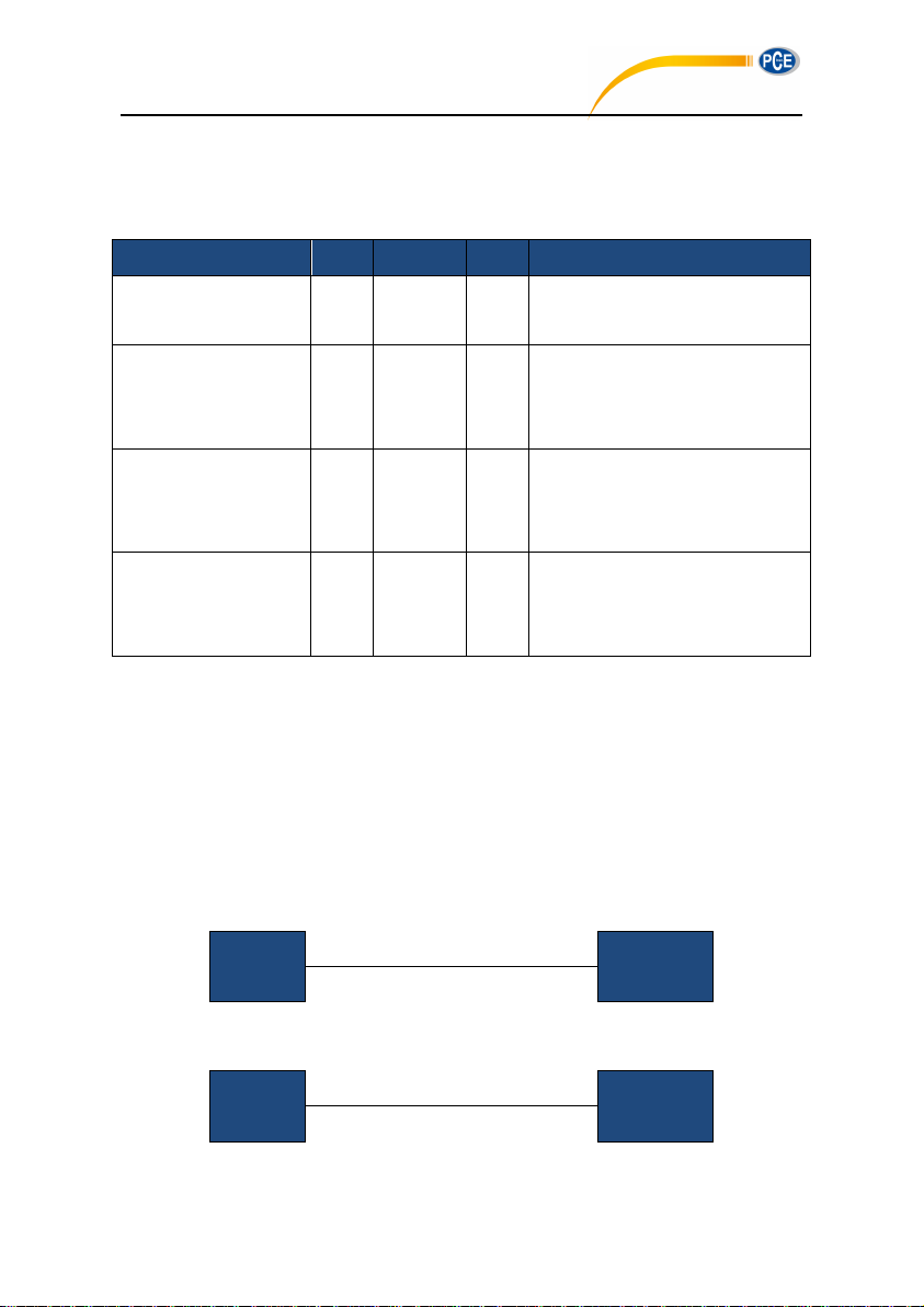
(1) Ensure that no same ID of sound level meter in each network.
Name
Min.
Rated
Max.
Description
Response time of
sound level meter
— — 2s
Time-out processing should be
operating when the value exceeds.
Time interval of
instruction sending to
sound level meter
—
100ms
—
—
Waiting time after
received <STX> for
sound level meter
—
Unlimited
—
Means that the sound level meter
will waiting for the remaining data
forever.
Time interval between
each byte for sound
level meter to receive
—
Unlimited
—
Means that the sending speed of
the computer could be very slow.
Computer
Set Instruction
—►
Sound Level
Meter
Computer
Set Instruction
—►
Sound Level
Meter
◄—
Return ACK
PCE-428 / 430 / 432
(2) User cannot broadcast command which can return any data.
5.2.9 Rated Parameters
5.3 Instruction
The instruction has two types: set instructions and query instructions.
Set Instructions: Set the measurement parameters and system parameters of sound level
meter.
Query Instructions: Query the parameters and data of the sound level meter.
There are 3 kind of situation for sending instruction to sound level meter: set instruction (no
response), set instructions (with response), query instructions.
(1) Set Instruction (no response):
(2) Set instructions (with response):
Normal response:
60
Page 57
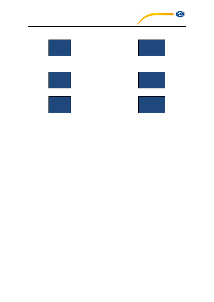
Error response:
Computer
Set Instruction
—►
Sound Level
Meter
◄—
Return NAK
Computer
Query Instruction
—►
Sound Level
Meter
◄—
Return Data
Computer
Query Instruction
—►
Sound Level
Meter
◄—
Return NAK
PCE-428 / 430 / 432
(3) Query command:
Normal response:
Error response:
61
Page 58

5.3.1 Instruction List
PCE-428 / 430 / 432
IDXp1: Setup ID ............................................................................................................ 66
IDX?: Query ID ............................................................................................................. 66
BRTp1: Set the RS-232 Baud Rate ............................................................................... 67
BRT?: Query The RS-232 Baud Rate Setting ................................................................ 67
XONp1: Set the Flow Control ....................................................................................... 68
XON?: Query Flow Control Setting ................................................................................ 68
RETp1: Set Response Mode ......................................................................................... 68
RET?: Query Response Mode Setting........................................................................... 69
MEMp1: Set the Measurement Mode ............................................................................ 69
MEM?: Query Measurement Mode Setting .................................................................... 70
CALp1: Set Calibration Level and Calibrate by Measurement ........................................ 70
CAL?: Query Calibration Level and Calibration Factor ................................................... 71
CAFp1: Calibrate by Calibration Factor ......................................................................... 71
CAF?: Query Calibration History ................................................................................... 71
BSEp1_p2_p3_p4_p5_p6_p7: Measurement Setup ...................................................... 72
BSE?: Query Measurement Setup ................................................................................ 73
RNS?: Query Measurement Range ............................................................................... 73
ICPp1: Set ICCP Power ................................................................................................ 74
ICP?: Query ICCP Power State ..................................................................................... 74
PR1p1_p2_p3_p4:Set Profile1 ................................................................................... 74
PR1?: Query Profile1 Setting ........................................................................................ 75
PR2p1_p2_p3_p4: Set Profile2 ..................................................................................... 75
PR2?: Query Profile2 Setting ........................................................................................ 75
PR3p1_p2_p3_p4: Set Profile3 ..................................................................................... 75
PR3?: Query Profile3 Setting ........................................................................................ 75
ALMp1: Set Alarm Threshold ........................................................................................ 76
ALM?: Query the Alarm Threshold Setting ..................................................................... 76
ETFp1_p2_p3_p4_p5: Set Extended Function .............................................................. 76
ETF?: Query Extended Function Setting ....................................................................... 77
62
Page 59

STSp1_p2_p3……p11_p12: Set Statistical ................................................................... 77
PCE-428 / 430 / 432
STS?: Query Statistical ................................................................................................. 78
HISp1_p2: Set Time History .......................................................................................... 78
HIS?: Query Time History Setting .................................................................................. 79
OCSp1_p2……p13_p14: Set Octave Threshold ............................................................ 79
OCS?: Query Octave Threshold Setting ........................................................................ 80
CUSp1_p2_p3_p4: Set Custom Measure .................................................................... 81
CUSp1_?: Query Custom Measure Setting ................................................................... 82
TISp1_p2_p3_p4_p5: Set Timer .................................................................................... 82
TIS?: Query Timer Setting ............................................................................................. 83
CONp1: Set Contrast .................................................................................................. 83
CON?: Query Contrast Setting ...................................................................................... 83
BLTp1_p2: Set Backlight ............................................................................................. 84
BLT?: Query Backlight Setting....................................................................................... 84
BAT?: Query Battery State .......................................................................................... 84
TRGp1: Set Trigger ..................................................................................................... 85
TRG?: Query Trigger Setting ....................................................................................... 85
DATp1_p2_p3_p4: Set Date ........................................................................................ 86
DAT?:Query Date Setting ........................................................................................... 86
HORp1_p2_p3: Set Time ............................................................................................ 86
HOR?: Query Time Setting .......................................................................................... 87
PWOp1: Set Auto Power Off ........................................................................................ 87
PWO?: Query Auto Power Off Setting .......................................................................... 87
OPMp1: Set Boot Mode ............................................................................................... 88
OPM?: Query Boot Mode Setting................................................................................. 88
UMDp1: Set USB Mode ................................................................................................ 89
UMD?: Query USB Mode Setting .................................................................................. 89
GPDp1_p2: Set GPS .................................................................................................... 89
GPD?: Query GPS Setting .......................................................................................... 90
VER?: Query About Information ................................................................................... 90
63
Page 60

LNGp1: Set Language ................................................................................................. 90
PCE-428 / 430 / 432
LNG?: Query Language Setting ................................................................................... 91
OUTp1_p2_p3_p4: Set Output .................................................................................... 91
OUT?: Query Output Setting ....................................................................................... 92
RES: Apply Factory Settings ......................................................................................... 92
STAp1: Start / Stop Measurement ............................................................................... 92
STA?: Query Measurement State ................................................................................ 93
DMAp1_?: Query the Main Screen Data ...................................................................... 93
TPRp1_?: Query 3-Profile Screen Data ....................................................................... 94
DLNp1_?: Query Statistical Analysis Data (LN) ............................................................ 94
DCU?: Query Custom Measure Data ........................................................................... 95
DSLp1_p2_?: Query All the Data of the Sound Level Meter ......................................... 96
DOT?: Query Octave Data .......................................................................................... 97
CSD: Save Custom Data into MicroSD ........................................................................ 98
64
Page 61

5.3.2 Instruction Format
PCE-428 / 430 / 432
In this section, “☐☐☐” on behalf of the 3 characters of the instruction, “p1, p2 ......” on behalf
of the parameter “d1, d2 ...” means the data, “_” means a space.
(1) Separate The Parameters By Space For Multiple Parameters In One Instruction:
☐☐☐ Instruction without parameters
☐☐☐p1 Instruction with 1 parameter
☐☐☐p1_p2 Instruction with 2 parameters
☐☐☐? Instruction with query parameter
☐☐☐p1_? Instruction with 1 parameter and a query parameter
☐☐☐p1_ p2_? Instruction with 2 parameters and a query parameter
The parameters can be a wide range, for example from 1 to 255. These parameters are
sending by the format of ASCII. Therefore, you may need to send 1~3 bytes.
☐☐☐93 Parameter is 93
☐☐☐124 Parameter is 124
Note that both of 93 and 124 are single parameter. So the individual numbers don’t need
to be separated by spaces.
☐☐☐1_64 2 individual parameters, 1 and 64
Note that 1 and 64 are two parameters in one instruction. So those parameters need to
be separated by space.
The parameter is possible to be decimal or integer type. However, if the actual value is
integer type, decimal point and decimal bits can be omitted.
(2) Separate The Data By Comma For Multiple Data In One Response
d1,d2,d3 Return 3 data
Response block, the data bits actually returned is less than its maximum possible
number of digits, leading zeros. For example, return 2 data with the maximum possible
value 255 (3 digits), and the actually data is 76 and 9, the response is:
076,009 Return data 76 and 9
If the returned data contains date and time, use the slash “/” to separate data and use the
colon “:” to separate the time:
2011/08/05,12:13:55
65
Page 62
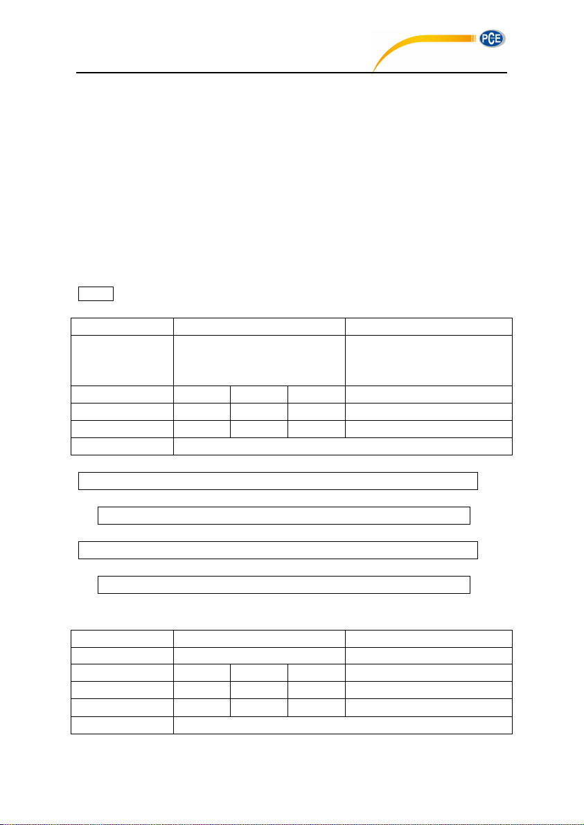
5.3.3 Instruction Describe
Instruction
Parameters
Explanation
IDX
p1: ID number;
Range: 1~255;
Default: 1
ASCII
I D X 1 Hex
49H
44H
58H
31H
Byte
1 1 1
1~3
Return
ACK / NAK
02 01 43 49 44 58 33 03 25 0D 0A
02 03 06 03 040D 0A
02 01 43 49 44 58 32 35 35 03 24 0D 0A
02 FF 06 03 F8 0D 0A
Instruction
Parameters
Explanation
IDX
Query parameter: ?
ASCII
I D X
?
Hex
49H
44H
58H
3FH
Byte
1 1 1 1 Return
Return the current ID number
PCE-428 / 430 / 432
Note in This Section:
In the following description, the value, range and default value of parameter are show as
ASCII code.
The default value means the sound level meter just delivery to user or restore to the
factory settings.
IDXp1: Setup ID
ID of sound level meters in one network must be different. Otherwise, there will be a
communication error.
☆Note: When the IDX instruction is correctly received by sound level meter, ACK signal will
be returned with the new ID.
Example 1: set the ID as 3.
Return: ACK. Note where ID has been changed to 3 (03H).
Example 2: set the ID as 255.
Return: ACK. Note where ID has been changed to 255 (FFH).
IDX?: Query ID
66
Page 63
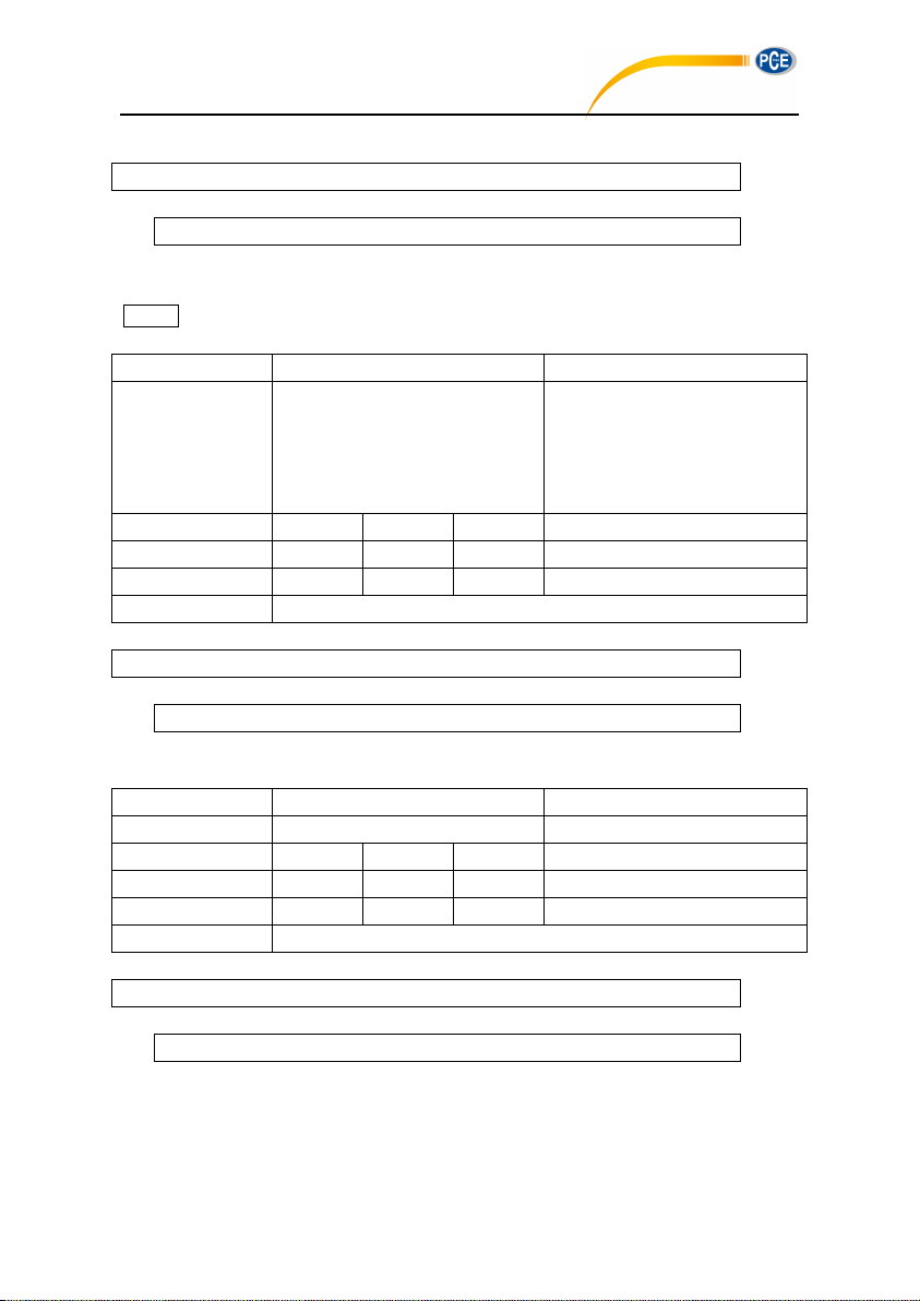
Example: query ID.
02 01 43 49 44 58 3F 03 29 0D 0A
02 01 41 30 30 31 03 70 0D 0A
Instruction
Parameters
Explanation
BRT
p1: RS-232 baud rate;
2=4800bps;
3=9600bps;
4=19200bps;
Default: 3
ASCII
B R T 3 Hex
42H
52H
54H
33H
Byte
1 1 1 1 Return
ACK / NAK
02 01 43 42 52 54 33 03 34 0D 0A
02 01 06 03 06 0D 0A
Instruction
Parameters
Explanation
BRT
Query parameter: ?
ASCII
B R T ? Hex
42H
52H
54H
3FH
Byte
1 1 1
1
Return
Return the current baud rate
02 01 43 42 52 54 3F 03 38 0D 0A
02 01 41 33 03 72 0D 0A
PCE-428 / 430 / 432
Return: the current ID 001.
BRTp1: Set the RS-232 Baud Rate
☆Note: When the BRT instruction is correctly received by the sound level meter, it will return
the ACK by previous baud rate, and then update the baud rate.
Example: set the baud rate to 9600bps.
Return: ACK.
BRT?: Query The RS-232 Baud Rate Setting
Example: query the current baud rate.
Return: the current baud rate is 9600bps.
67
Page 64
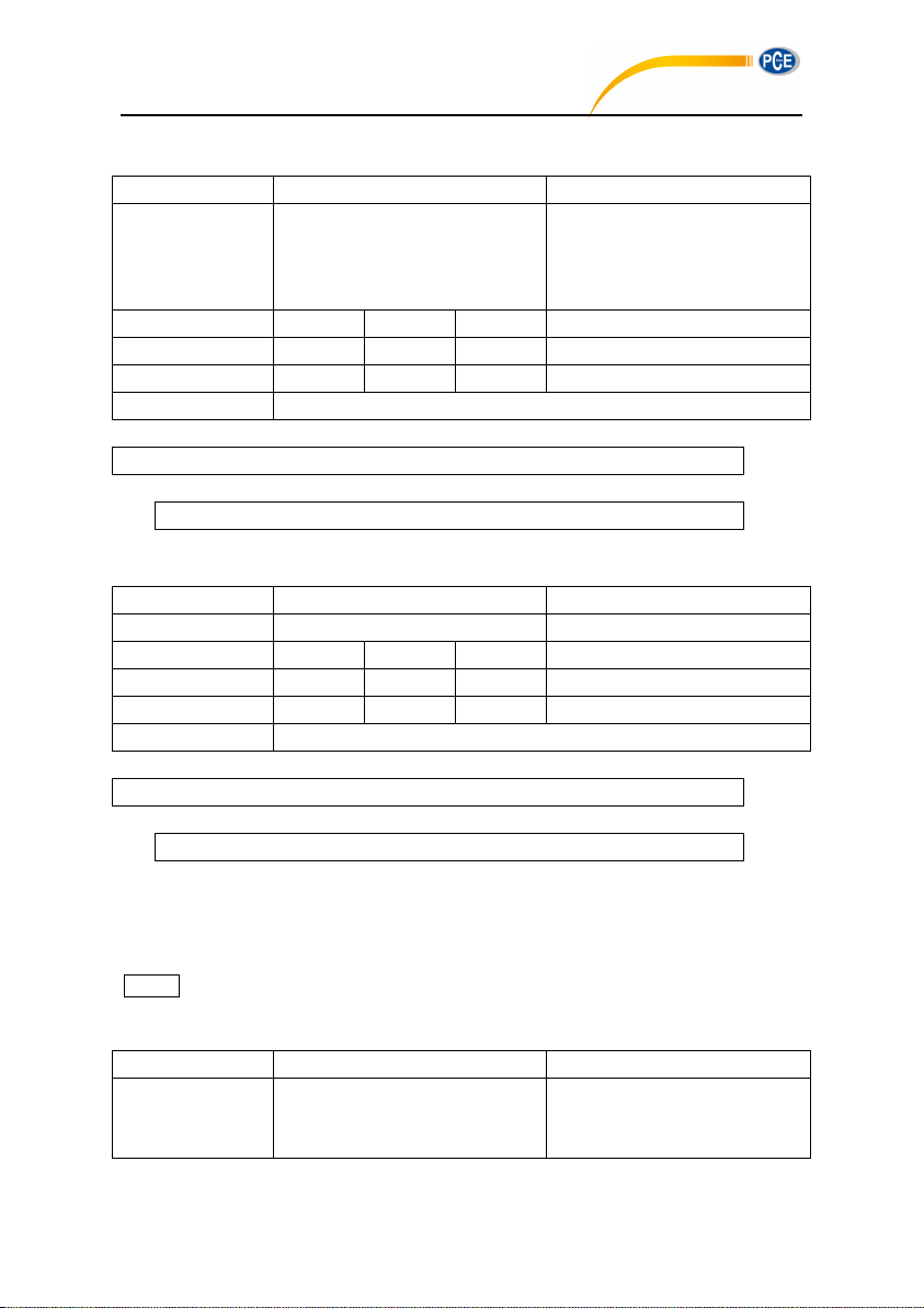
XONp1: Set the Flow Control
Instruction
Parameters
Explanation
XON
p1: Flow control mode;
0=Hardware flow control;
1=Software flow control;
Default: 1
ASCII
X O N 1 Hex
58H
4FH
4EH
31H
Byte
1 1 1 1 Return
ACK / NAK
02 01 43 58 4F 4E 31 03 2B 0D 0A
02 01 06 03 06 0D 0A
Instruction
Parameters
Explanation
XON
Query parameter: ?
ASCII
X O N ? Hex
58H
4FH
4EH
3FH
Byte
1 1 1 1 Return
Return flow control mode
02 01 43 58 4F 4E 3F 03 25 0D 0A
02 01 41 31 03 70 0D 0A
Instruction
Parameters
Explanation
RET
p1: Response mode;
0=Disabled;
1=Enabled;
PCE-428 / 430 / 432
Example: set to software flow control mode.
Return: ACK.
XON?: Query Flow Control Setting
Example: query flow control mode.
Return: the current flow control mode is software flow control.
RETp1: Set Response Mode
Response means the ACK / NAK signal returned from the sound level meter (HIS and OCS
instruction returns MicroSD card state or NAK).User can enable or disable such a response.
☆Note: RET instruction itself is not affected by response mode. When the sound level meter
receive the RET instruction, it will return ACK/NAK whether the current state is enabled or
disabled. RET? Query command is also not subject to the influence of response mode.
68
Page 65
Default: 1
ASCII
R E T 1 Hex
52H
45H
54H
31H
Byte
1 1 1 1 Return
ACK / NAK
Example: set to enable response.
02 01 43 52 45 54 31 03 31 0D 0A
02 01 06 03 06 0D 0A
Instruction
Parameters
Explanation
RET
Query parameter: ?
ASCII
R E T ? Hex
52H
45H
54H
3FH
Byte
1 1 1 1 Return
Return response mode
02 01 43 52 45 54 3F 03 3F 0D 0A
02 01 41 31 03 70 0D 0A
Instruction
Parameters
Explanation
MEM
p1: Measurement mode;
0=1/1Octave;
1=Level meter mode;
2=1/3 Octave (Optional);
Default: 1
ASCII
M E M
1
Hex
4DH
45H
4DH
31H
Byte
1 1 1 1 Return
ACK / NAK
PCE-428 / 430 / 432
Return: ACK.
RET?: Query Response Mode Setting
Example: query response mode.
Return: the current response mode is to enable the response.
MEMp1: Set the Measurement Mode
When MEM instruction is correctly received by the sound level meter, it will switch to the main
screen of the octave mode or the main screen of level meter mode according to the
corresponding parameter in instruction.
☆Note: The 1/3 octave band is optional function.
69
Page 66
Example: set the sound level meter mode.
02 01 43 4D 45 4D 31 03 37 0D 0A
02 01 06 03 06 0D 0A
Instruction
Parameters
Explanation
MEM
Query parameter: ?
ASCII
M E M ? Hex
4DH
45H
4DH
3FH
Byte
1 1 1 1 Return
Return the measurement mode
02 01 43 4D 45 4D 3F 03 39 0D 0A
02 01 41 31 03 70 0D 0A
Instruction
Parameters
Explanation
CAL
p1: Calibration level;
Range: 0~199.9;
Default: 93.8
ASCII
C A L
93.8
Hex
43H
41H
4CH
39H,33H,2EH,38H
Byte
1 1 1
1~5
Return
ACK / NAK
02 01 43 43 41 4C 39 34 03 00 0D 0A
02 01 06 03 06 0D 0A
02 01 06 03 06 0D 0A
PCE-428 / 430 / 432
Return: ACK.
MEM?: Query Measurement Mode Setting
Example: query the measurement mode.
Returns: the current measurement mode is level meter mode.
CALp1: Set Calibration Level and Calibrate by Measurement
☆Note: When CAL instruction is correctly received by the sound level meter, two ACK will be
returned at the beginning and the end of the calibration (several seconds will be spent by the
calibration). In the calibration history, ending with symbol M indicate the record was calibrate
by the method of by Measurement.
Example 1: set the calibration level as 94dB and calibrate by measurement.
Return: ACK.
Return again after calibration finished: ACK
Example 2: set the calibration level as 113.8dB and calibrate by measurement.
70
Page 67
02 01 43 43 41 4C 31 31 33 2E 38 03 28 0D 0A
Return: ACK.
02 01 06 03 06 0D 0A
02 01 06 03 06 0D 0A
Instruction
Parameters
Explanation
MEM
Query parameter: ?
ASCII
C A L ? Hex
43H
41H
4CH
3FH
Byte
1 1 1 1 Return
Return the value of the calibration level and calibration factor
02 01 43 43 41 4C 3F 03 32 0D 0A
02 01 41 30 39 34 2E 30 2C 2B 30 30 30 2E 30 30 03 7B 0D 0A
Instruction
Parameters
Explanation
CAF
p1: Calibration factor;
Range: -199.99~+199.99 (“+”
sign can be omitted);
Default: 0
ASCII
C A F 0 Hex
43H
41H
46H
30H
Byte
1 1 1
1~7
Return
ACK / NAK
02 01 43 43 41 46 30 2E 37 34 03 1A 0D 0A
02 01 06 03 06 0D 0A
PCE-428 / 430 / 432
Return again after calibration finished: ACK
CAL?: Query Calibration Level and Calibration Factor
Example: query the calibration level and calibration factor.
Return: the current calibration level is 094.0dB, the calibration factor is 000.00dB.
CAFp1: Calibrate by Calibration Factor
This instruction can modify the calibration factor. In the calibration history, code “F” at the end
of each line means by calibration factor.
Example: set the calibration factor value as 0.74dB (“+” sign is omitted).
Return: ACK.
CAF?: Query Calibration History
Query the most recent 4 group history of calibration.
71
Page 68
Instruction
Parameters
Explanation
CAF
Query parameter: ?
ASCII
C A F ? Hex
43H
41H
46H
3FH
Byte
1 1 1
1
Return
Returns the most recent 4 group history of calibration.
Format “Year/Month/day, hour:minute:second, calibration factor, code”.
Code: M=By Measurement, F=By Calibration Factor.
Example: query the calibration history.
02 01 43 43 41 46 3F 03 38 0D 0A
02 01 41 32 30 31 31 2F 30 38 2F 30 34 2C 31 37 3A 30 33 3A 32 38 2C 2B
30 30 31 2E 32 39 2C 46 2C 32 30 31 31 2F 30 38 2F 30 34 2C 31 37 3A 30
33 3A 30 32 2C 2B 30 30 31 2E 32 35 2C 46 2C 32 30 31 31 2F 30 38 2F 30
34 2C 31 37 3A 30 32 3A 32 30 2C 2B 30 30 30 2E 37 31 2C 46 2C 32 30 31
31 2F 30 38 2F 30 34 2C 31 37 3A 30 32 3A 30 30 2C 2B 30 30 31 2E 32 37
2C 4D 03 62 0D 0A
Instructi
on
P1
P2
P3
P4
P5
P6
P7
Explanat
ion
BSE
p1: delay;
1~60=1~6
0s;
61=Sync.
1m;
62=Sync.
15m;
63=Sync.
30m;
64=Sync.
1h;
Default: 1
p2:
integral
period;
0=Inf;
1~59=1~5
9s;
60~118=1
~59m;
119~142=
1h~24h;
Default: 0
p3:
repeat;
0=Inf;
1~9999
=1~9999
times;
Default: 0
p4: SWN
logger;
0=disable
;
1=enable;
Default: 0
p5:SWN
logger ;st
ep
0=0.1s;
1=0.2s;
2=0.5s;
3~61=1~5
9s;
62~120=1
~59m;
121~144=
1h~24h;
Default: 3
p6:CSD
logger;
0=disable
;
1=enable;
Default: 0
p7:CSD
logger
step;
0~58=1~5
9s;
59~117=1
~59m;
118~141=
1~24h;
Default:
59
ASCII
B S E 1 0 0 0 3 0
59
PCE-428 / 430 / 432
Return: the data returned by this instruction use a slash “/” split date, use a colon “,” split time.
Calibration history is 2011/08/04, 17:03:28, +001.29, F, 2011/08/04, 17:03:02, +001.25, F,
2011/08/04, 17:02:20, +000.71, F, 2011/08/04, 17:02:00, +001.27, M.
BSEp1_p2_p3_p4_p5_p6_p7: Measurement Setup
Set the delay, integral period, repeat, and logger setup.
72
Page 69
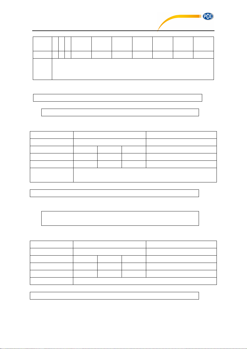
Hex
42H 53H 45
H
31H
30H
30H
30H
33H
30H
35H, 39H
Byte
1 1 1
1~2
1~3
1~4 1 1~3 1 1~2
Return
Returns:
0=setting succeed, MicroSD card is OK; 1=setting succeed, but the MicroSD card is
abnormal; 2=setting succeed, but no MicroSD card detected.
Example: set delay as 2s, integral period as 5m, repeat as infinite, SWN logger enable, SWN
02 01 43 42 53 45 32 20 36 34 20 30 20 31 20 31 20 31 20 31 03 17 0D 0A
02 01 41 30 03 71 0D 0A
Instruction
Parameters
Explanation
BSE
Query parameter: ?
ASCII
B S E ? Hex
42H
53H
45H
3FH
Byte
1 1 1
1
Return
Return parameter of measurement setup: delay, integral period,
repeat, SWN logger, SWN logger step, CSD Logger, CSD Logger step.
02 01 43 42 53 45 3F 03 28 0D 0A
02 01 41 30 32 2C 30 36 34 2C 30 30 30 30 2C 31 2C 30 30 31 2C 31 2C 30
30 31 03 71 0D 0A
Instruction
Parameters
Explanation
RNG
Query parameter: ?
ASCII
R N S ? Hex
52H
4EH
53H
3FH
Byte
1 1 1 1 Return
Return measurement range
02 01 43 52 4E 53 3F 03 33 0D 0A
PCE-428 / 430 / 432
logger step as 0.2s, CSD logger enable, CSD logger step as 2s.
Returns: setting succeeds, MicroSD card is OK.
BSE?: Query Measurement Setup
Example: query the measurement setup.
Returns: the current measurement setup: delay=2s, integral period=5min, repeat=infinite,
SWN logger=enable, SWN logger step= 0.2s, CSD logger=enable, CSD logger step=2s.
RNS?: Query Measurement Range
Example: query measurement range.
Return: linearity, dynamic and peak C range is 22.8-133.8, 12.8-133.8, 44.8-136.8.
73
Page 70
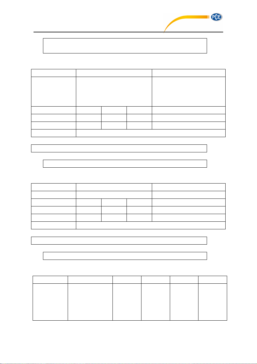
02 01 41 30 32 32 2E 38 7E 31 33 33 2E 38 2C 30 31 32 2E 38 7E 31 33 33
2E 38 2C 30 34 34 2E 38 7E 31 33 36 2E 38 03 38 0D 0A
ICPp1: Set ICCP Power
Instruction
Parameters
Explanation
ICP
p1: ICCP power state;
0=Enable;
1=Disable;
Default: 0
ASCII
I C P 0 Hex
49H
43H
50H
30H
Byte
1 1 1 1 Return
ACK / NAK
02 01 43 49 43 50 30 03 29 0D 0A
02 01 06 03 06 0D 0A
Instruction
Parameters
Explanation
ICP
Query parameter: ?
ASCII
I C P ? Hex
49H
43H
50H
3FH
Byte
1 1 1 1 Return
Return ICCP power state
02 01 43 49 43 50 3F 03 26 0D 0A
02 01 41 30 03 71 0D 0A
Instruction
P1
P2
P3
P4
Explanation
PR1
p1:
Filter;
0=A;
1=B;
2=C;
p2:
Detector;
0=Fast;
1=Slow;
2=Imp;
p3:
Integration
mode;
0=SPL;
1=PEAK;
p4:
SWN
Logger;
0=LEQ;
1=PEAK;
PCE-428 / 430 / 432
Example: enable ICCP power:
Return: ACK.
ICP?: Query ICCP Power State
Example: query ICCP power state
Return: ICCP power is enable
PR1p1_p2_p3_p4:Set Profile1
74
Page 71
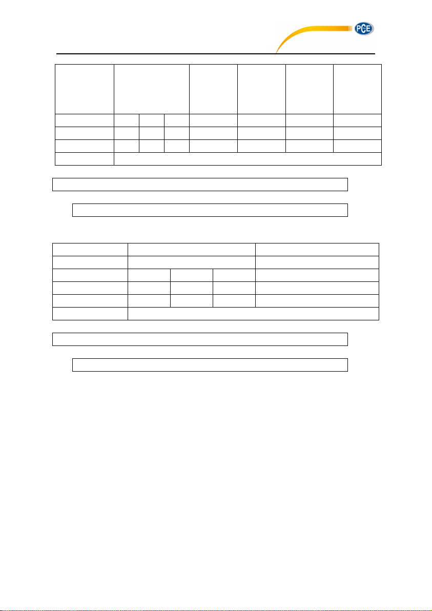
3=Z;
Default: 0
Default: 0
2=LEQ;
3=MAX;
4=MIN;
Default: 0
2=MAX;
3=MIN;
Default: 0
ASCII
P R 1 0 0 0 0
Hex
50H
52H
31H
30H
30H
30H
30H
Byte
1 1 1 1 1 1 1
Return
ACK / NAK
Example: set Profile1 as A, Fast, SPL and save LEQ.
02 01 43 50 52 31 30 20 30 20 30 20 30 03 50 0D 0A
02 01 06 03 06 0D 0A
Instruction
Parameters
Explanation
PR1
Query parameter: ?
ASCII
P R 1 ? Hex
50H
52H
31H
3FH
Byte
1 1 1 1 Return
Return Profile1 setting
02 01 43 50 52 31 3F 03 4F 0D 0A
02 01 41 30 2C 30 2C 30 2C 30 03 6D 0D 0A
PCE-428 / 430 / 432
Return: ACK.
PR1?: Query Profile1 Setting
Example: query Profile1 setting.
Return: current Profile1 setting is A, Fast, SPL, save LEQ.
PR2p1_p2_p3_p4: Set Profile2
Except the instruction is “PR2” and the default filter is 2 (C-weighting), all others are same to
the “PR1”.
PR2?: Query Profile2 Setting
Except the instruction is “PR2”, all others are same to the “PR1?”.
PR3p1_p2_p3_p4: Set Profile3
Except the instruction is “PR3” and the default filter is 3 (Z-weighting), all others are same to
the “PR1”.
PR3?: Query Profile3 Setting
75
Page 72
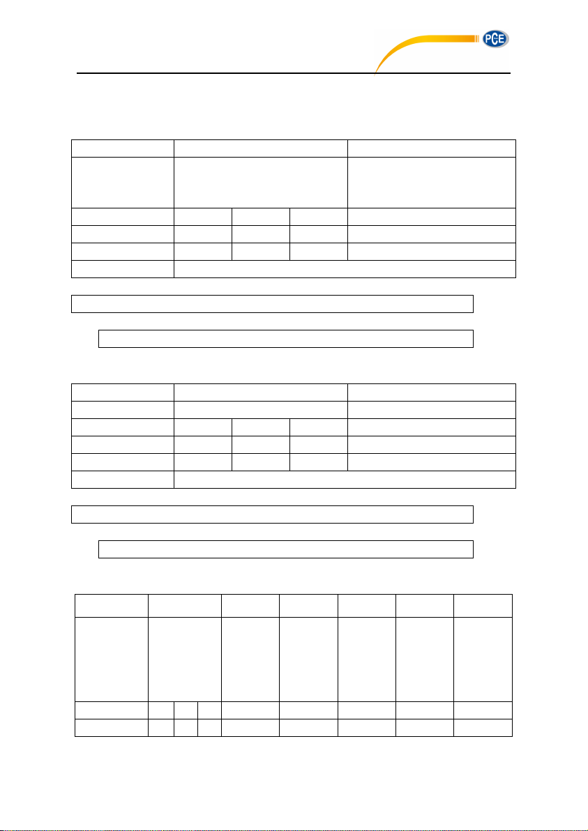
Except the instruction is “PR3”, all others are same to the “PR1?”.
Instruction
Parameters
Explanation
ALM
p1: Alarm threshold;
Range: 20~200;
Default: 100
ASCII
A L M
100
Hex
41H
4CH
4DH
31H, 30H, 30H
Byte
1 1 1
1~3
Return
ACK / NAK
02 01 43 41 4C 4D 31 30 30 03 32 0D 0A
02 01 06 03 06 0D 0A
Instruction
Parameters
Explanation
ALM
Query parameter: ?
ASCII
A L M ? Hex
41H
4CH
4DH
3FH
Byte
1 1 1 1 Return
Return alarm threshold
02 01 43 41 4C 4D 3F 03 3C 0D 0A
02 01 41 31 30 30 03 70 0D 0A
Instruction
P1
P2
P3
P4
P5
Explanation
ETF
p1:
3Profile
Screen;
0=Disable;
1=Enable
p2:
Statistical
Screen;
0=Disable;
1=Enable
p3: Time
History
Screen;
0=Disable;
1=Enable
p4:
Custom
Screen;
0=Disable;
1=Enable
p5: GPS
Screen;
0=Disable;
1=Enable
ASCII
E T F 1 1 1 1 1 Hex
45H
54H
46H
31H
31H
31H
31H
31H
PCE-428 / 430 / 432
ALMp1: Set Alarm Threshold
Example: setting alarm threshold as 100dB.
Return: ACK.
ALM?: Query the Alarm Threshold Setting
Example: query alarm threshold.
Return: the current alarm threshold is 100dB.
ETFp1_p2_p3_p4_p5: Set Extended Function
76
Page 73
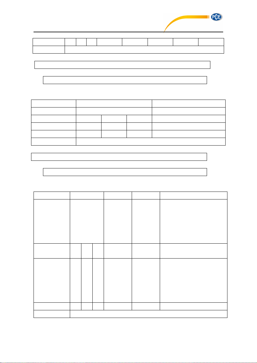
Byte
1 1 1 1 1 1 1 1 Return
ACK / NAK
Example: enable 3Profile, statistical, time history, custom, GPS.
02 01 43 45 54 46 31 20 31 20 31 20 31 20 31 03 25 0D 0A
02 01 06 03 06 0D 0A
Instruction
Parameters
Explanation
ETF
Query parameter: ?
ASCII
E T F ? Hex
45H
54H
46H
3FH
Byte
1 1 1 1 Return
Return the extended function setting
02 01 43 45 54 46 3F 03 2B 0D 0A
02 01 41 31 2C 31 2C 31 2C 31 2C 31 03 70 0D 0A
Instruction
P1
P2
P3~P12
Explanation
STS
p1: Filter
0=A;
1=B;
2=C;
3=Z;
Default: 0
p2: Detector
0=F;
1=S;
2=I;
Default: 0
p3~p12: statistical percentage;
Range: 1~99;
Default: 10, 20, 30, 40, 50, 60,
70, 80, 90, 99
ASCII
S T S 0 0
10_20_30_40_50_
60_70_80_90_99
Hex
53H
54H
53H
30H
30H
31H, 30H, 20H, 32H, 30H, 20H,
33H, 30H, 20H, 34H, 30H, 20H,
35H, 30H, 20H, 35H, 30H, 20H,
36H, 30H, 20H, 37H, 30H, 20H,
38H, 30H, 20H, 39H, 30H, 20H,
39H, 39H
Byte
1 1 1 1 1
10~20+9 (spaces)
Return
ACK / NAK
PCE-428 / 430 / 432
Return: ACK
ETF?: Query Extended Function Setting
Example: query the extended function setting
Return: 3Profile, statistical, time history, custom and GPS are all enable
STSp1_p2_p3……p11_p12: Set Statistical
77
Page 74
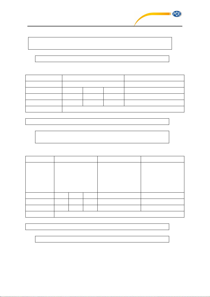
Example: set filter as B, detector as I, percentage as 10, 20, 30, 40, 50, 60, 70, 80, 90 and 99.
02 01 43 53 54 53 31 20 32 20 31 30 20 32 30 20 33 30 20 34 30 20 35 30 20 36 30
20 37 30 20 38 30 20 39 30 20 39 39 03 35 0D 0A
02 01 06 03 06 0D 0A
Instruction
Parameters
Explanation
STS
Query parameter: ?
ASCII
S T S ? Hex
53H
54H
53H
3FH
Byte
1 1 1 1 Return
Return filter, detector and 10 percentage of statistical
02 01 43 53 54 53 3F 03 28 0D 0A
02 01 41 31 2C 32 2C 31 30 2C 32 30 2C 33 30 2C 34 30 2C 35 30 2C 36 30
2C 37 30 2C 38 30 2C 39 30 2C 39 39 03 6F 0D 0A
Instruction
Parameters 1
Parameters 2
Explanation
HIS
p1: Profile;
0=Profile1;
1=Profile2;
2=Profile3;
Default: 1
p2: Duration;
0=1min;
1=2min;
2=10min;
Default: 1
ASCII
H I S
1
1
Hex
48H
49H
53H
31H
31H
Byte
1 1 1
1
1
Return
ACK / NAK
02 01 43 48 49 53 31 20 31 03 31 0D 0A
02 01 06 03 06 0D 0A
PCE-428 / 430 / 432
Return: ACK.
STS?: Query Statistical
Example: query statistical
Return: filter=B, detector=I, percentage=10, 20, 30, 40, 50, 60, 70, 80, 90, 99.
HISp1_p2: Set Time History
Example: set Profile2 as data sources and duration as 2min.
Return: ACK.
78
Page 75
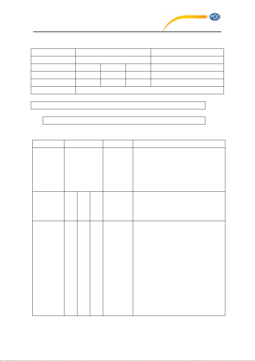
HIS?: Query Time History Setting
Instruction
Parameters
Explanation
HIS
Query parameter: ?
ASCII
H I S ? Hex
48H
49H
53H
3FH
Byte
1 1 1 1 Return
Return time history setting
02 01 43 48 49 53 3F 03 2E 0D 0A
02 01 41 31 2C 31 03 6D 0D 0A
Instruction
Parameter 1
Parameter 2~41
Explanation
OCS
p1:Filter
0=Z;
1=C;
2=B;
3=A;
Default: 0
p2~p41: The threshold of LeqA, LeqB,
LeqC, LeqZ, 6.3Hz~20kHz;
Range: 0-199.9;
Default: 31.5Hz=79, 63Hz=63, 125Hz=52,
250Hz=44, others=38
ASCII
O C S
1
38_38_38_38_38_38_38_38_38_38_38_79
_38_38_63_38_38_52_38_38_44_38_38_3
8_38_38_38_38_38_38_38_38_38_38_38_
38_38_38_38_38
Hex
4FH
43H
53H
31H
33H,38H,20H,33H,38H,20H,33H,
38H,20H,33H,38H,20H,33H,38H,
20H,33H,38H,20H,33H,38H,20H,
33H,38H,20H,33H,38H,20H,33H,
38H,20H,33H,38H,20H,37H,39H,
20H,33H,38H,20H,33H,38H,20H,
36H,33H,20H,33H,38H,20H,33H,
38H,20H,35H,32H,20H,33H,38H,
20H,33H,38H,20H,34H,34H,20H,
33H,38H,20H,33H,38H,20H,33H,
38H,20H,33H,38H,20H,33H,38H,
20H,33H,38H,20H,33H,38H,20H,
33H,38H,20H,33H,38H,20H,33H,
PCE-428 / 430 / 432
Example: query time history setting.
Returns: the current data sources=Profile2, duration=2min.
OCSp1_p2……p13_p14: Set Octave Setting
79
Page 76
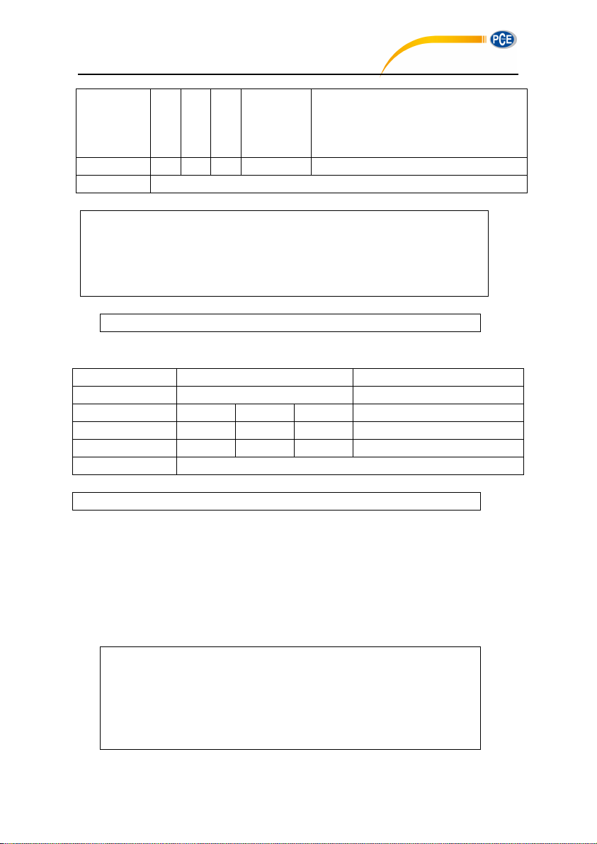
38H,20H,33H,38H,20H,33H,38H,
20H,33H,38H,20H,33H,38H,20H,
33H,38H,20H,33H,38H,20H,33H,
38H,20H,33H,38H,20H,33H,38H
Byte
1 1 1
1
80+39 (space)
Return
ACK / NAK
Example: set Filter as C-weighting; all the threshold values are 38.
02 01 43 4F 43 53 31 20 33 38 20 33 38 20 33 38 20 33 38 20 33 38 20 33 38 20 33
38 20 33 38 20 33 38 20 33 38 20 33 38 20 33 38 20 33 38 20 33 38 20 33 38 20 33
38 20 33 38 20 33 38 20 33 38 20 33 38 20 33 38 20 33 38 20 33 38 20 33 38 20 33
38 20 33 38 20 33 38 20 33 38 20 33 38 20 33 38 20 33 38 20 33 38 20 33 38 20 33
38 20 33 38 20 33 38 20 33 38 20 33 38 20 33 38 20 33 38 03 00 0D 0A
02 01 06 03 06 0D 0A
Instruction
Parameters
Explanation
OCS
Query parameter: ?
ASCII
O C S ? Hex
4FH
43H
53H
3FH
Byte
1 1 1 1 Return
Return octave setting
02 01 43 4F 43 53 3F 03 23 0D 0A
02 01 41 31 2C 30 33 38 2E 31 2C 30 33 38 2E 32 2C 30 33 38 2E 33 2C 30
33 38 2E 34 2C 30 33 38 2E 31 2C 30 33 38 2E 32 2C 30 33 38 2E 33 2C 30
33 38 2E 34 2C 30 33 38 2E 35 2C 30 33 38 2E 36 2C 30 33 38 2E 37 2C 30
33 38 2E 38 2C 30 33 38 2E 39 2C 30 33 38 2E 31 2C 30 36 33 2E 32 2C 30
33 38 2E 33 2C 30 33 38 2E 34 2C 30 35 32 2E 35 2C 30 33 38 2E 36 2C 30
33 38 2E 37 2C 30 34 34 2E 38 2C 30 33 38 2E 39 2C 30 33 38 2E 31 2C 30
PCE-428 / 430 / 432
Return: ACK
OCS?: Query Octave Setting
Example: query octave setting.
Returns: return Filter and threshold of LeqA, LeqB, LeqC, LeqZ, 6.3Hz~20kHz. For example:
Filter is C-weighting, threshold are LeqA=038.1;LeqB=038.2;LeqC=038.3;LeqZ=038.4;
6.3Hz=038.1; 8Hz=038.2 ; 10Hz=038.3 ; 12.5Hz=038.4; 16Hz=038.5; 20Hz=038.6 ;
25Hz=038.7; 31.5Hz=038.8 ; 40Hz=038.9 ; 50Hz=038.1; 63Hz=063.2; 80Hz=038.3 ;
100Hz=038.4;125Hz=052.5;160Hz=038.6;200Hz=038.7;250Hz=044.8;315Hz=038.9;
400Hz=038.1;500Hz=038.2;630Hz=038.3;800Hz=038.4;1kHz=038.5;1.25kHz=038.6;
1.6kHz=038.7;2kHz=038.8;2.5kHz=038.9;3.15kHz=038.1;4kHz=038.2;5kHz=038.3;
6.3kHz=038.4;8kHz=038.5;10kHz=038.6;12.5kHz=038.7;16kHz=038.8;20kHz=038.9
80
Page 77
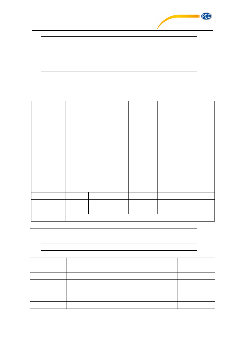
33 38 2E 32 2C 30 33 38 2E 33 2C 30 33 38 2E 34 2C 30 33 38 2E 35 2C 30
33 38 2E 36 2C 30 33 38 2E 37 2C 30 33 38 2E 38 2C 30 33 38 2E 39 2C 30
33 38 2E 31 2C 30 33 38 2E 32 2C 30 33 38 2E 33 2C 30 33 38 2E 34 2C 30
33 38 2E 35 2C 30 33 38 2E 36 2C 30 33 38 2E 37 2C 30 33 38 2E 38 2C 30
33 38 2E 39 03 7D 0D 0A
Instruction
P1
P2
P3
P4
Explanation
CUS
p1: Group;
Range: 1~14
p2: Filter;
0=A;
1=B;
2=C;
3=Z
p3: Detector;
0=Fast;
1=Slow;
2=Imp.
p4: Mode;
0=SPL;
1=SD;
2=SEL;
3=E;
4=Max;
5=Min;
6=Peak;
7=LEQ;
8=LN1;
……
17=LN10
ASCII
C U S 1 0 0 0
Hex
43H
55H
53H
31H
30H
30H
30H
Byte
1 1 1
1~2 1 1
1~2
Return
ACK / NAK
02 01 43 43 55 53 31 20 31 20 30 20 36 03 20 0D 0A
02 01 06 03 06 0D 0A
Filter
Detector
Mode
Meaning
Custom 1
0 0 7
A, Fast*, LEQ
Custom 2
0 0 8
A*, Fast*, LN1
Custom 3
0 0 12
A*, Fast*, LN5
Custom 4
0 0 16
A*, Fast*, LN 9
Custom 5
0 0 4
A, Fast, Max
Custom 6
0 0 5
A, Fast, Min
PCE-428 / 430 / 432
CUSp1_p2_p3_p4: Set Custom Measure
Example: set custom measurement of group 1 to B-weighting, Fast, Peak.
Return: ACK
Default value of each group in custom measurement (parameter with * is actually useless):
81
Page 78
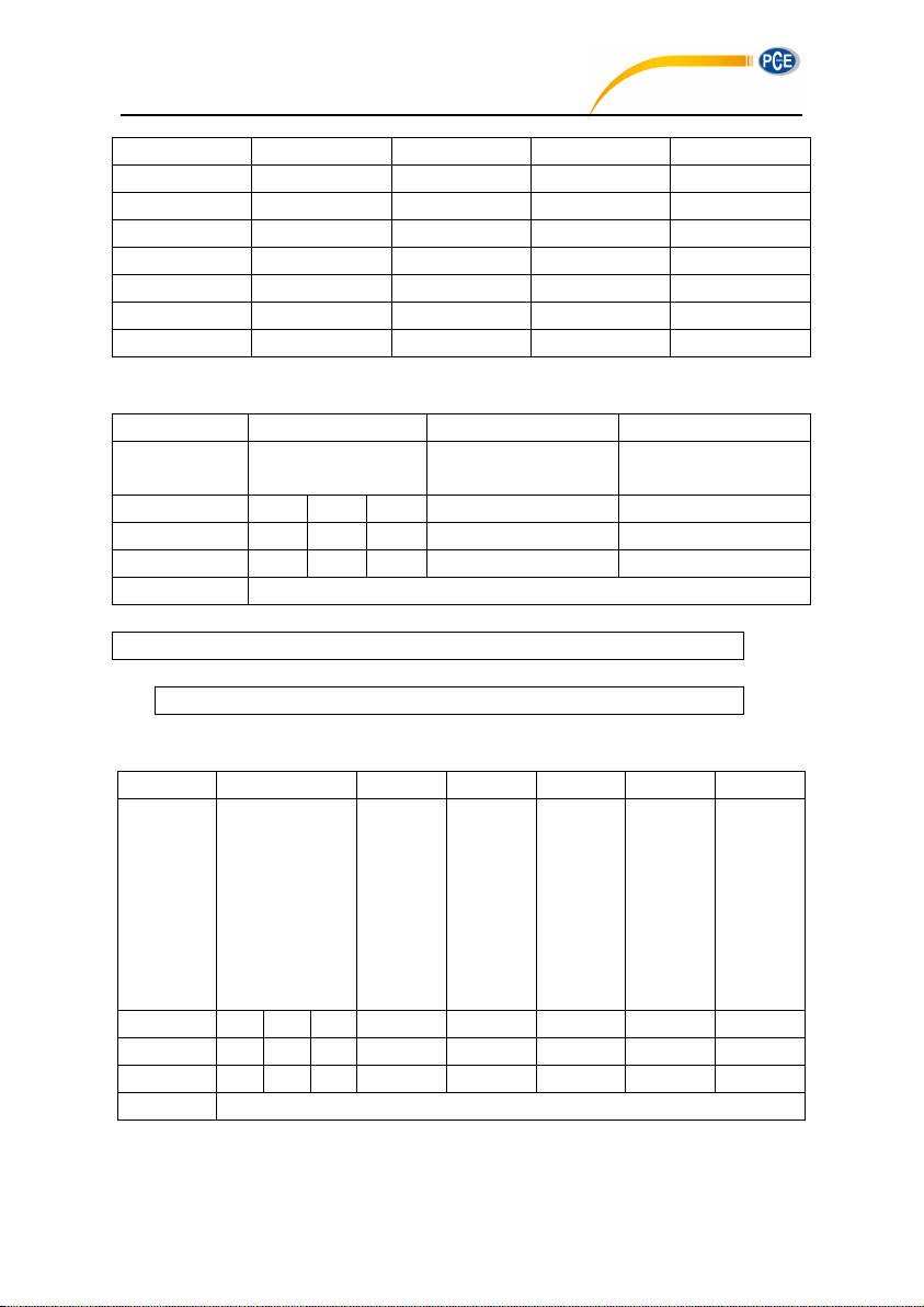
Custom 7
0 0 1
A, Fast, SD
Custom 8
0 0 0
A, Fast, SPL
Custom 9
1 0 0
B, Fast, SPL
Custom 10
2 0 0
C, Fast, SPL
Custom 11
3 0 0
Z, Fast, SPL
Custom 12
0 0 2
A, Fast*, SEL
Custom 13
0 0 3
A, Fast*, E
Custom 14
2 0 6
C, Fast*, Peak
CUSp1_?: Query Custom Measure Setting
Instruction
P1
P2
Explanation
CUS
p1: Group
1~14
Query parameter: ?
ASCII
C U S
1
?
Hex
43H
55H
53H
31H
3FH
Byte
1 1 1
1~2
1
Return
Return custom measure setting
02 01 43 43 55 53 31 32 20 3F 03 1A 0D 0A
02 01 41 31 32 2C 30 2C 30 2C 30 33 03 6D 0D 0A
Instruction
P1
P2
P3
P4
P5
Explanatio
n
TIS
P1:
Switch;
0=OFF;
1=ON;
Default: 0
p2: Start
Day;
0=Ignore;
1~31=
1~31 day
form
today;
Default: 0
p3: Start
hour;
0~23=
0~23h;
Default:
12
p4: Start
minute;
0~59=
0~59m;
Default: 0
P5:
Repeat
period;
1~59=
1~59m;
60~83=
1~24h;
Default: 1
ASCII
T I S 0 0
12 0 1
Hex
54H
49H
53H
30H
30H
31H, 32H
30H
31H
Byte
1 1 1 1 1
1~2
1~2
1~2
Return
ACK / NAK
PCE-428 / 430 / 432
Example: query custom measure settings of group 12.
Return: the setting of group 12 is A-weighting, Fast, E.
TISp1_p2_p3_p4_p5: Set Timer
Example: set the Timer as switch: ON, start day: Ignore, start hour: 12:00, repeat period: 1m.
82
Page 79
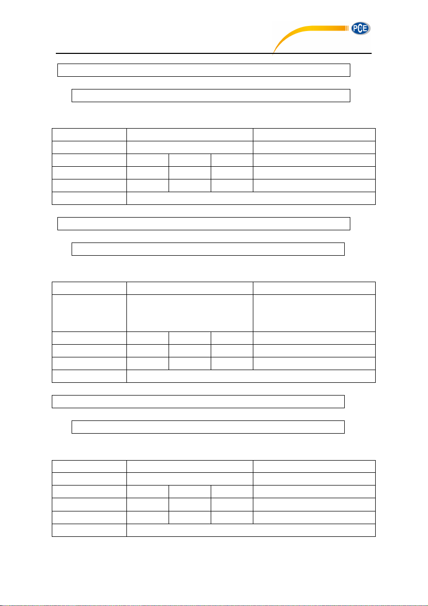
02 01 43 54 49 53 31 20 30 20 31 32 20 30 20 31 03 0E 0D 0A
Return: ACK
02 01 06 03 06 0D 0A
Instruction
Parameters
Explanation
TIS
Query parameter: ?
ASCII
54H
49H
53H ? Hex
1 1 1
3FH
Byte
54H
49H
53H 1 Return
Return Timer setting
02 01 43 54 49 53 3F 03 32 0D 0A
02 01 41 30 2C 30 30 2C 31 32 3A 30 30 2C 30 31 03 65 0D 0A
Instruction
Parameters
Explanation
CON
p1: Contrast;
Range:0~14;
Default: 7
ASCII
C O N 7 Hex
43H
4FH
4EH
37H
Byte
1 1 1 1 Return
ACK / NAK
02 01 43 43 4F 4E 39 03 38 0D 0A
02 01 06 03 06 0D 0A
Instruction
Parameters
Explanation
CON
Query parameter: ?
ASCII
C O N
?
Hex
43H
4FH
4EH
3FH
Byte
1 1 1 1 Return
Return contrast setting
PCE-428 / 430 / 432
TIS?: Query Timer Setting
Example: query Timer setting.
Return: Timer setting is switch=OFF, start day=Ignore, Start Time=12:00, Repeat period=1m.
CONp1: Set Contrast
Example: set the contrast as 9.
Return: ACK
CON?: Query Contrast Setting
83
Page 80
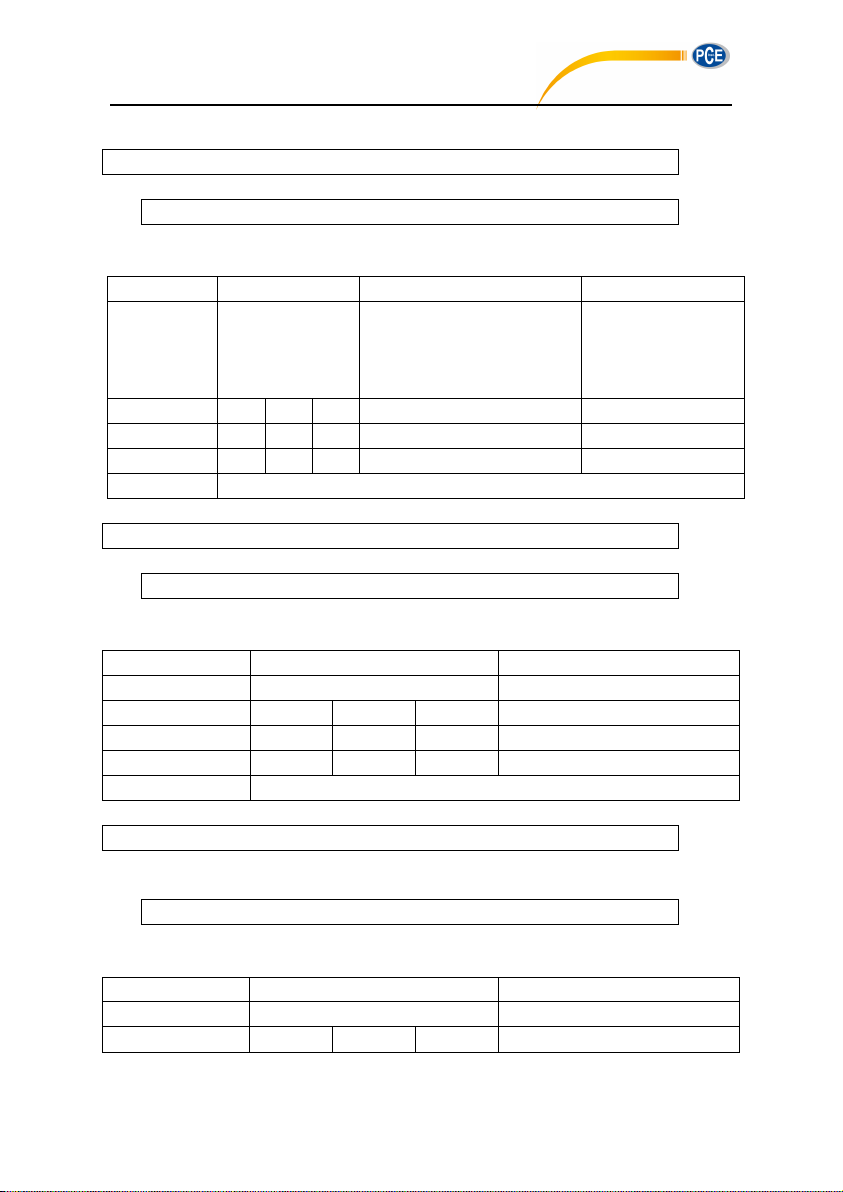
Example: query contrast setting
02 01 43 43 4F 4E 3F 03 3E 0D 0A
02 01 41 30 37 03 46 0D 0A
Instruction
Parameter 1
Parameter 2
Explanation
BLT
p1: TimeOut;
0=ON, Auto shut down;
1=OFF, Never turn off;
Default: 0
p2: Delay;
0=10s; 1=20s; 2=30s;
3=40s; 4=50s; 5=60s;
Default: 0
ASCII
B L T
0
0
Hex
42H
4CH
54H
30H
30H
Byte
1 1 1
1
1
Return
ACK / NAK
02 01 43 42 4C 54 30 20 31 03 38 0D 0A
02 01 06 03 06 0D 0A
Instruction
Parameters
Explanation
BLT
Query parameter: ?
ASCII
B L T ? Hex
42H
4CH
54H
3FH
Byte
1 1 1 1 Return
Return backlight settings
02 01 43 42 4C 54 3F 03 26 0D 0A
02 01 41 31 2C 31 03 6D 0D 0A
Instruction
Parameters
Explanation
BAT
Query parameter: ?
ASCII
B A T
?
PCE-428 / 430 / 432
Returns: the current contrast is 7
BLTp1_p2: Set Backlight
Example: set backlight as timeout: ON, delay: 20s
Return: ACK
BLT?: Query Backlight Setting
Example: query the backlight settings
Return: the current backlight setting is timeout=OFF, delay=20s (delay is useless when
backlight timeout is OFF)
BAT?: Query Battery State
84
Page 81
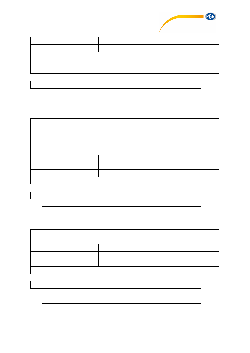
Hex
42H
41H
54H
3FH
Byte
1 1 1
1
Return
Returns the power state and supply voltage
Power state: 0=Battery; 1=External power; 2=USB power
Supply voltage: xx.xx V
Example: query battery state
02 01 43 42 41 54 3F 03 2B 0D 0A
02 01 41 31 2C 30 39 2E 32 34 03 7D 0D 0A
Instruction
Parameters
Explanation
TRG
p1: Trigger switch;
0=OFF;
1=ON;
Default: 0
ASCII
T R G 0 Hex
54H
52H
47H
30H
Byte
1 1 1 1 Return
ACK / NAK
02 01 43 54 52 47 30 03 32 0D 0A
02 01 06 03 06 0D 0A
Instruction
Parameters
Explanation
TRG
Query parameter: ?
ASCII
T R G
?
Hex
54H
52H
47H
3FH
Byte
1 1 1 1 Return
Return Trigger settings
02 01 43 54 52 47 3F 03 3D 0D 0A
02 01 41 30 03 71 0D 0A
PCE-428 / 430 / 432
Returns: the current battery state is external power supply, supply voltage is 9.24V
TRGp1: Set Trigger
Example: set trigger as OFF
Return: ACK
TRG?: Query Trigger Setting
Example: query trigger setting
Returns: the current trigger setting is OFF
85
Page 82
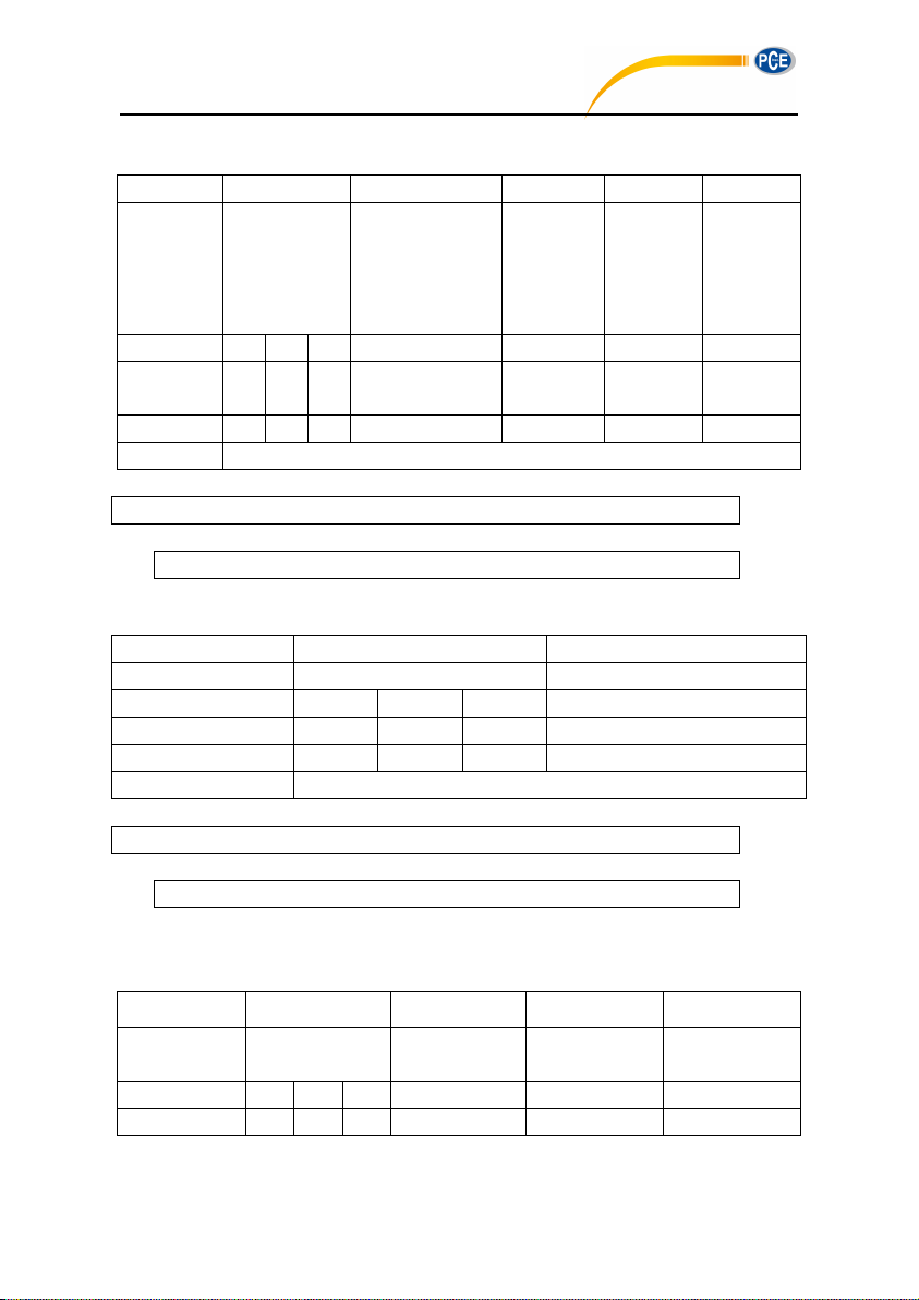
DATp1_p2_p3_p4: Set Date
Instruction
P1
P2
P3
P4
Explanation
DAT
p1: Date format;
0=Year/Month/Day;
1=Month/Day/Year;
2=Day/Year/Month;
Default: 0
p2: Year;
Range:
2000~2999
p3: Month;
Range:
1~12
p4: Day;
Range:
1~31
ASCII
D A T 0 2011 1 1
Hex
44H
41H
54H
30H
32H, 30H
31H, 31H
31H
31H
Byte
1 1 1 1 4
1~2
1~2
Return
ACK / NAK
02 01 43 44 41 54 30 20 32 30 31 31 20 38 20 35 03 0D 0D 0A
02 01 06 03 06 0D 0A
Instruction
Parameters
Explanation
DAT
Query parameter: ?
ASCII
D A T ? Hex
44H
41H
54H
3FH
Byte
1 1 1 1 Return
Return date setting
02 01 43 44 41 54 3F 03 2D 0D 0A
02 01 41 30 2C 32 30 31 31 2F 30 38 2F 30 35 03 52 0D 0A
Instruction
P1
P2
P3
Explanation
HOR
p1: Hour;
Range: 0~23h
p2: Minute;
Range: 0~59m
p3: Second;
Range: 0~59s
ASCII
H O R 1 1 1 Hex
48H
4FH
52H
31H
31H
31H
PCE-428 / 430 / 432
Example: set the date format as year/month/day, date: 5th August 2011
Return: ACK
DAT?:Query Date Setting
Example: query date
Return: the current date format=year/month/day, date=5th August 2011
HORp1_p2_p3: Set Time
86
Page 83
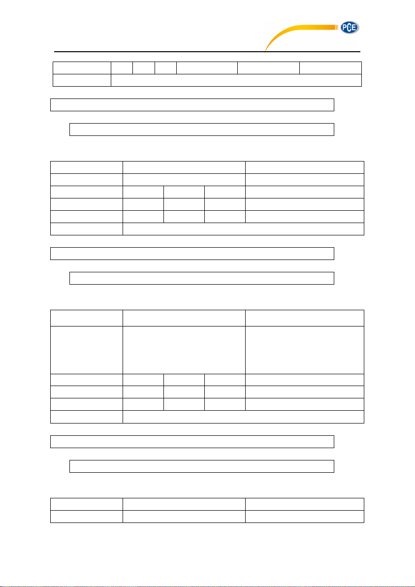
Byte
1 1 1
1~2
1~2
1~2
Return
ACK / NAK
Example: set the time as 18:37:30
02 01 43 48 4F 52 31 38 20 33 37 20 33 30 03 18 0D 0A
02 01 06 03 06 0D 0A
Instruction
Parameters
Explanation
HOR
Query parameter: ?
ASCII
H O R ? Hex
48H
4FH
52H
3FH
Byte
1 1 1 1 Return
Return time settings
02 01 43 48 4F 52 3F 03 29 0D 0A
02 01 41 31 38 3A 33 37 3A 34 38 03 40 0D 0A
Instruction
Parameters
Explanation
PWO
p1: Auto power off time;
0=1min; 1=5min; 2=10min;
3=30min; 4=OFF;
Default: 4
ASCII
P W O 4 Hex
50H
57H
4FH
34H
Byte
1 1 1 1 Return
ACK / NAK
02 01 43 50 57 4F 34 03 3F 0D 0A
02 01 06 03 06 0D 0A
Instruction
Parameters
Explanation
PWO
Query parameter: ?
PCE-428 / 430 / 432
Return: ACK
HOR?: Query Time Setting
Example: query time setting
Returns: the current time is 18:37:48
PWOp1: Set Auto Power Off
Example: set auto power off as OFF
Return: ACK
PWO?: Query Auto Power Off Setting
87
Page 84
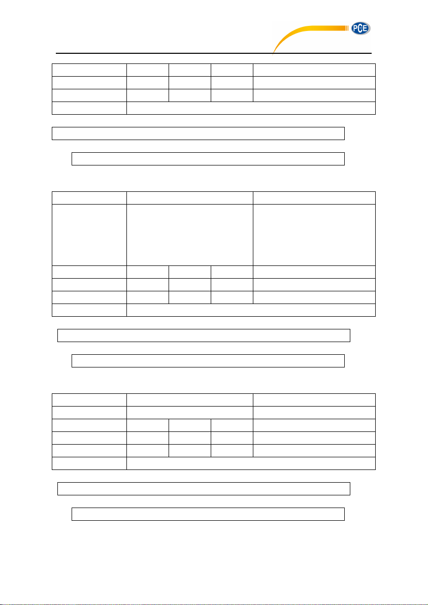
ASCII
P W O ? Hex
50H
57H
4FH
3FH
Byte
1 1 1 1 Return
Return auto power off settings
Example: query auto power off settings
02 01 43 50 57 4F 3F 03 34 0D 0A
02 01 41 34 03 75 0D 0A
Instruction
Parameters
Explanation
OPM
p1: Boot mode;
0=Normal;
1=Power & Boot;
2=Boot & Auto Measure;
Default: 0
ASCII
O P M 0 Hex
4FH
50H
4DH
30H
Byte
1 1 1 1 Return
ACK / NAK
02 01 43 4F 50 4D 30 03 21 0D 0A
02 01 06 03 06 0D 0A
Instruction
Parameters
Explanation
OPM
Query parameter: ?
ASCII
O P M
?
Hex
4FH
50H
4DH
3FH
Byte
1 1 1 1 Return
Return boot mode setting
02 01 43 4F 50 4D 3F 03 2E 0D 0A
02 01 41 30 03 71 0D 0A
PCE-428 / 430 / 432
Returns: the current auto power off setting is OFF
OPMp1: Set Boot Mode
Example: set bott mode as normal
Return: ACK
OPM?: Query Boot Mode Setting
Example: query boot mode
Return: the current boot mode is normal
88
Page 85
UMDp1: Set USB Mode
Instruction
Parameters
Explanation
UMD
p1: USB Mode;
0=Always Ask;
1=U Disk Mode;
2=Modem Mode;
Default: 0
ASCII
U M D
0
Hex
55H
4DH
44H
30H
Byte
1 1 1 1 Return
ACK / NAK
02 01 43 55 4D 44 32 03 2D 0D 0A
02 01 06 03 06 0D 0A
Instruction
Parameters
Explanation
UMD
Query parameter: ?
ASCII
U M D ? Hex
55H
4DH
44H
3FH
Byte
1 1 1 1 Return
Return USB mode setting
02 01 43 55 4D 44 3F 03 20 0D 0A
02 01 41 32 03 73 0D 0A
Instruction
P1
P2
Explanation
GPD
p1: GPS switch;
0=OFF;
1=ON;
Default: 0
p2: Auto time sync;
0=OFF;
1=ON;
Default: 0
ASCII
G P D
0
0
PCE-428 / 430 / 432
Example: set to modem mode
Return: ACK
UMD?: Query USB Mode Setting
Example: query USB mode setting
Return: the current USB mode is modem mode
GPDp1_p2: Set GPS
89
Page 86
Hex
47H
50H
44H
30H
30H
Byte
1 1 1
1
1
Return
ACK / NAK
Example: set GPS as switch: ON, auto time sync: ON
02 01 43 47 50 44 31 20 31 03 30 0D 0A
02 01 06 03 06 0D 0A
Instruction
Parameters
Explanation
GPD
Query parameter: ?
ASCII
G P D ? Hex
47H
50H
44H
3FH
Byte
1 1 1 1 Return
Return GPS setting
02 01 43 47 50 44 3F 03 2D 0D 0A
02 01 41 31 2C 31 03 6F 0D 0A
Instruction
Parameters
Explanation
VER
Query parameter: ?
ASCII
V E R ? Hex
56H
45H
52H
3FH
Byte
1 1 1 1 Return
Return the about information
02 01 43 56 45 52 3F 03 3D 0D 0A
02 01 41 33 30 39 53 2C 32 2C 34 39 30 30 30 31 2C 33 2E 30 30 2E 31 34
31 30 32 30 2C 50 30 32 37 34 2E 30 33 2E 42 31 31 03 33 0D 0A 03 70 0D
0A
Instruction
Parameters
Explanation
LNG
p1: Language selection;
PCE-428 / 430 / 432
Return: ACK
GPD?: Query GPS Setting
Example: query GPS setting
Returns: the current GPS setting is switch=ON, auto time sync=ON
VER?: Query About Information
Example: query about information
Returns: type=309S, class=2, S/N=490001, version=3.00.141020, HWID=P0274.03.B11
LNGp1: Set Language
90
Page 87
0=English; 1=Chinese;
2=Portuguese; 3=Spanish;
4=German; 5=French;
Default: 0
ASCII
L N G 0 Hex
4CH
4EH
47H
30H
Byte
1 1 1 1 Return
ACK / NAK
Example: set the language as Chinese
02 01 43 4C 4E 47 31 03 37 0D 0A
02 01 06 03 06 0D 0A
Instruction
Parameters
Explanation
LNG
Query parameter: ?
ASCII
L N G ? Hex
4CH
4EH
47H
3FH
Byte
1 1 1 1 Return
Return the language setting
02 01 43 4C 4E 47 3F 03 39 0D 0A
02 01 41 31 03 70 0D 0A
Instruction
P1
P2
P3
P4
Explanation
OUT
p1: Filter of
SLM;
0=A;
1=B;
2=C;
3=Z;
Default: 0
p2:
Detector of
SLM;
0=Fast;
1=Slow;
2=Imp.;
Default: 0
p3: Mode
of SLM;
0=SPL;
1=LEQ;
2=Peak;
Default: 0
p4: Output of
Octave;
0=LAeq;
1=LBeq;
2=LCeq;
3=LZeq;
4~39=6.3Hz~20kHz;
Default: 0
ASCII
O U T 0 0 0 0
Hex
4FH
55H
54H
30H
30H
30H
30H
PCE-428 / 430 / 432
Return: ACK
LNG?: Query Language Setting
Example: query language setting
Returns: the current language is Chinese
OUTp1_p2_p3_p4: Set Output
91
Page 88
Byte
1 1 1 1 1 1 1~2
Return
ACK / NAK
Example: set the output to A-weighting, Fast, SPL for SLM. Set the output to LAeq for Octave
02 01 43 4F 55 54 30 20 30 20 30 20 30 03 2D 0D 0A
02 01 06 03 06 0D 0A
Instruction
Parameters
Explanation
OUT
Query parameter: ?
ASCII
O U T ? Hex
4FH
55H
54H
3FH
Byte
1 1 1 1 Return
Return output setting
02 01 43 4F 55 54 3F 03 32 0D 0A
02 01 41 30 2C 30 2C 30 2C 30 03 6D 0D 0A
Instruction
Parameters
Explanation
RES
None
ASCII
R E S
None
Hex
52H
45H
53H
None
Byte
1 1 1
None
Return
ACK / NAK
02 01 43 52 45 53 03 07 0D 0A
02 01 06 03 06 0D 0A
Instruction
Parameters
Explanation
STA
p1: Start / Stop measurement;
0=Stop;
1=Start
PCE-428 / 430 / 432
Return: ACK
OUT?: Query Output Setting
Example: query output setting
Return: the output for SLM=A-weighting, Fast, SPL. For Octave=LAeq
RES: Apply Factory Settings
☆Note: After receipt of the ACK, user must wait at least 6 seconds to finish the operation.
Example: apply the factory settings
Return: ACK. Wait at least 6 seconds after receipt of ACK
STAp1: Start / Stop Measurement
92
Page 89
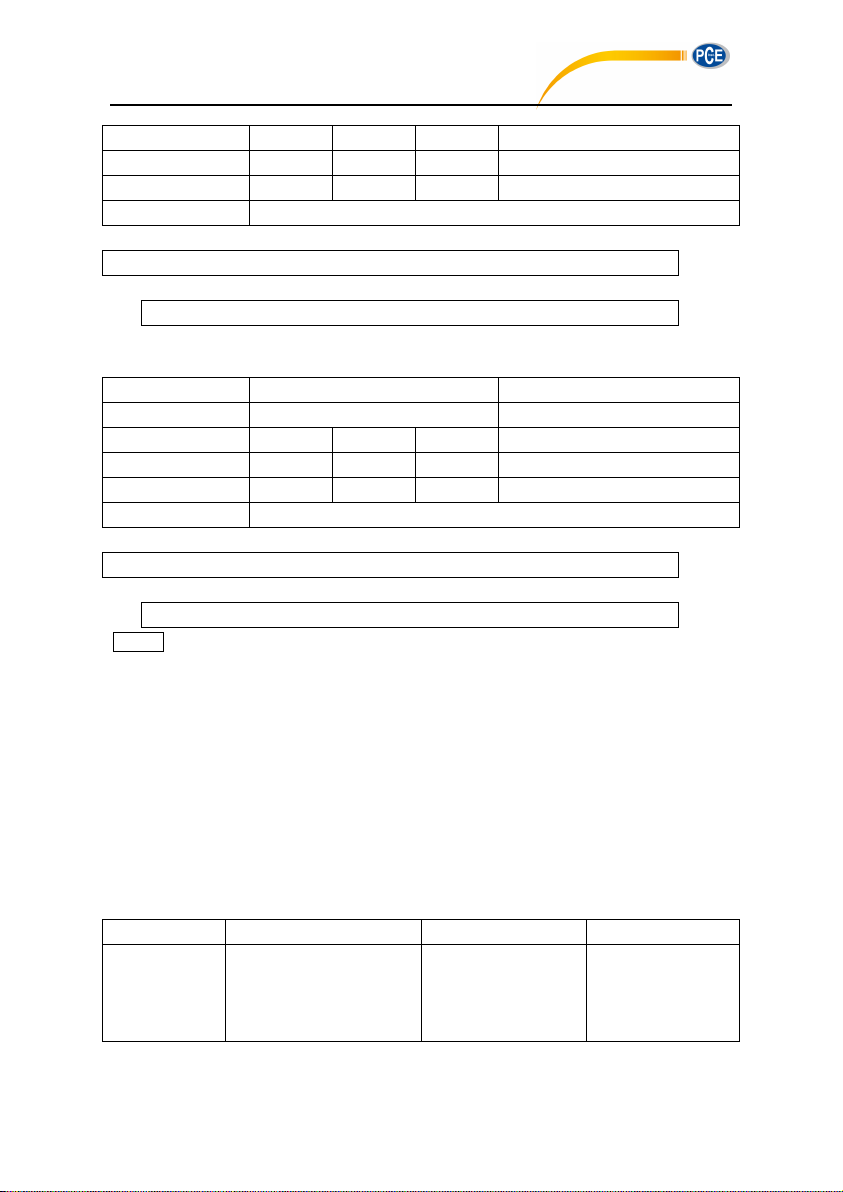
ASCII
S T A 1 Hex
53H
54H
41H
31H
Byte
1 1 1 1 Return
ACK / NAK
Example: start measurement
02 01 43 53 54 41 31 03 34 0D 0A
02 01 06 03 06 0D 0A
Instruction
Parameters
Explanation
STA
Query parameter: ?
ASCII
S T A ? Hex
53H
54H
41H
3FH
Byte
1 1 1 1 Return
Return measurement state
02 01 43 53 54 41 3F 03 3A 0D 0A
02 01 41 31 03 70 0D 0A
Instruction
P1
P2
Explanation
DMA
p1:Return manner
0=Stop return
1=Single return
2=Continuous return
Query parameter: ?
PCE-428 / 430 / 432
Return: ACK
STA?: Query Measurement State
Example: query the measurement state
Returns: the measurement state is start (running)
☆Note: The following instructions are to query the sound level meter measurements data.
They contain the "return manner” parameter, it means:
Stop return: The sound level meter no longer to return measurements data every
second after received this instruction.
Single return: The sound level meter will return the measurements data on time after
received the instruction.
Continuous return: Automatically return the measurements data every second after
received the instruction.
Therefore, the "return manner" parameter in the instruction can be set to 2 and send to the
sound level meter, sound level meter will return the latest measurements data every second.
DMAp1_?: Query the Main Screen Data
93
Page 90
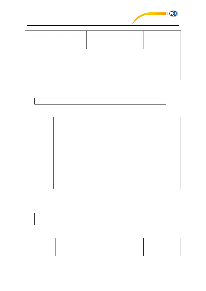
ASCII
D M A 1 ?
Hex
44H
4DH
41H
31H
3FH
Byte
1 1 1 1 1
Return
Return the main screen data
Filter: 0=A, 1=B, 2=C, 3=Z
Detector: 0=Fast, 1=Slow, 2=Imp.
Mode: 0=SPL, 1=PEAK, 2=LEQ, 3=MAX, 4=MIN
Measurement data: The value of the main screen
Example: query the data of the main screen, and return only once
02 01 43 44 4D 41 31 20 3F 03 25 0D 0A
02 01 41 31 2C 31 2C 32 2C 30 36 36 2E 31 03 70 0D 0A
Instruction
P1
P2
Explanation
TPR
p1: Return manner;
0=Stop return;
1=Single return;
2=Continuous return
Query parameter: ?
ASCII
T P R 1 ?
Hex
54H
50H
52H
31H
3FH
Byte
1 1 1 1 1
Return
Return 3-Profile screen data
Profile 1: Filter, Detector, Mode, Data
Profile 2: Filter, Detector, Mode, Data
Profile 3: Filter, Detector, Mode, Data
02 01 43 54 50 52 31 20 3F 03 3B 0D 0A
02 01 41 31 2C 31 2C 32 2C 30 36 36 2E 31 2C 32 2C 30 2C 30 2C 30 36 37
2E 31 2C 33 2C 30 2C 30 2C 30 36 37 2E 34 03 74 0D 0A
Instruction
P1
P2
Explanation
DLN
p1: Return manner;
0=Stop return;
Query parameter: ?
PCE-428 / 430 / 432
Returns: the current main screen is: B-weighting, Slow, measurement data 066.1dB
TPRp1_?: Query 3-Profile Screen Data
Example: query 3-Profile screen data
Returns: the current 3-Profile screen data: profile 1: B-weighting, LEQ, 066.1dB; profile 2:
C-weighting, Fast, SPL, 067.1dB; profile 3: Z-weighting, Fast, SPL, 067.4dB
DLNp1_?: Query Statistical Analysis Data (LN)
94
Page 91
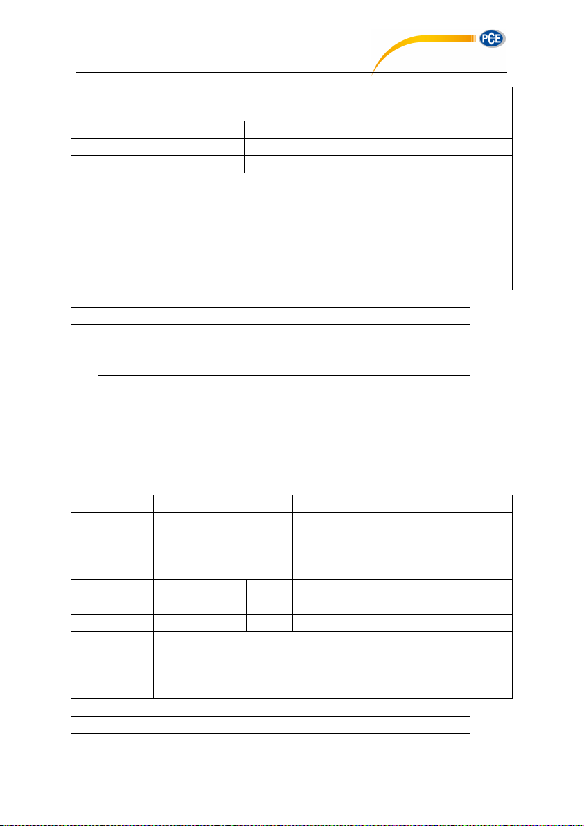
1=Single return;
2=Continuous return
ASCII
D L N 1 ?
Hex
44H
4CH
4EH
31H
3FH
Byte
1 1 1 1 1
Return
Return statistical analysis (LN) data
Filter: 0=A, 1=B, 2=C, 3=Z
Detector: 0=Fast, 1=Slow, 2=Imp.
Mode: 0=SPL
Group 1 LN percentages and LN statistics
……
Group 10 LN percentages and LN statistics
Example: query statistical analysis (LN) data
02 01 43 44 4C 4E 31 20 3F 03 2B 0D 0A
02 01 41 30 2C 30 2C 30 2C 31 30 2C 30 36 35 2E 34 2C 32 30 2C 30 36 35
2E 34 2C 33 30 2C 30 36 35 2E 34 2C 34 30 2C 30 36 35 2E 33 2C 35 30 2C
30 36 35 2E 33 2C 36 30 2C 30 36 35 2E 33 2C 37 30 2C 30 36 35 2E 32 2C
38 30 2C 30 36 35 2E 32 2C 39 30 2C 30 36 35 2E 32 2C 39 39 2C 30 36 35
2E 31 2C 03 58 0D 0A
Instruction
P1
P2
Explanation
DCU
p1: Return manner;
0=Stop return;
1=Single return;
2=Continuous return
Query parameter: ?
ASCII
D C U 1 ?
Hex
44H
43H
55H
31H
3FH
Byte
1 1 1 1 1
Return
Return custom measure data:
Group 1Filter, Detector, Mode, Data
……
Group 14Filter, Detector, Mode, Data
02 01 43 44 43 55 31 20 3F 03 3F 0D 0A
PCE-428 / 430 / 432
Returns: the current statistical analysis data is: A-weighting, Fast, SPL, LN10=065.4dB,
LN20=065.4dB, LN30=065.4dB, LN40=065.3dB, LN50=065.3dB, LN60=065.3dB,
LN70=035.2dB, LN80=065.2dB, LN 90=065.2dB, LN99=065.1dB
DCU?: Query Custom Measure Data
Example: query custom measure data
95
Page 92
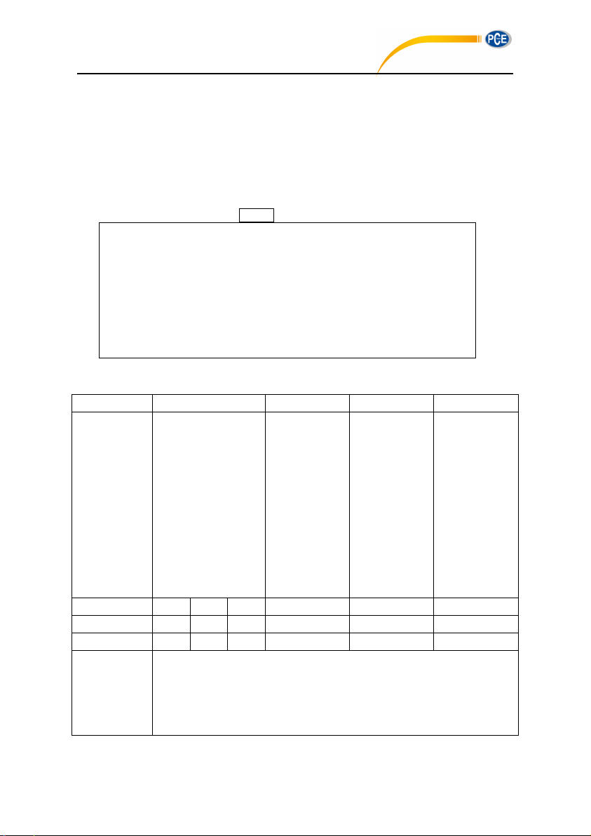
Returns: the current custom measure data: Group 0: A-weighting, Fast*, L10, 065.4dB;
02 01 41 30 2C 30 2C 30 38 2C 30 36 35 2E 34 2C 30 2C 30 2C 30 39 2C 30
36 35 2E 34 2C 30 2C 30 2C 31 33 2C 30 36 35 2E 33 2C 30 2C 30 2C 31 37
2C 30 36 35 2E 31 2C 30 2C 30 2C 30 35 2C 30 36 34 2E 34 2C 30 2C 30 2C
30 36 2C 30 38 31 2E 39 2C 30 2C 30 2C 30 32 2C 30 38 33 2E 38 2C 30 2C
30 2C 30 30 2C 30 36 35 2E 33 2C 31 2C 30 2C 30 30 2C 30 36 36 2E 34 2C
30 2C 30 2C 30 31 2C 30 30 35 2E 36 2C 31 2C 30 2C 30 31 2C 30 30 37 2E
32 2C 30 2C 30 2C 30 33 2C 32 2E 36 39 36 65 2D 30 35 2C 30 2C 30 2C 30
34 2C 30 36 35 2E 35 2C 31 2C 30 2C 30 37 2C 30 36 36 2E 32 03 2F 0D 0A
Instruction
P1
P2
P3
Explanation
DSL
p1: Data
group;
0=SPL;
1=SD;
2=SEL;
3=E;
4=Max;
5=Min;
6=Peak;
7=Leq;
8=LN
p2: Return
manner;
0=Stop return;
1=Single
return;
2=Continuous
return
Query
parameter: ?
ASCII
D S L 0 1 ? Hex
44H
53H
4CH
30H
31H
3FH
Byte
1 1 1 1 1
1
Return
Return the corresponding group data:
Group 0: LAF, LAS, LAI, LBF, LBS, LBI, LCF, LCS, LCI, LZF, LZS, LZI
Group 1: LAFsd, LASsd, LAIsd, LBFsd, LBSsd, LBIsd, LCFsd, LCSsd,
LCIsd, LZFsd, LZSsd, LZIsd
Group 2: LAsel, LBsel, LCsel, LZsel
PCE-428 / 430 / 432
Group 1: A-weighting, Fast*, L20, 065.4dB; Group 2: A-weighting, Fast*, L60, 065.3dB;
Group 3: A-weighting, Fast*, L99, 065.1dB; Group 4: A-weighting, Fast, Min, 064.4dB; Group
5: A-weighting, Fast*, Peak, 081.9dB; Group 6: A-weighting, Fast, Sel, 083.8dB; Group7:
A-weighting, Fast, SPL, 065.3dB; Group 8: B-weighting, Fast, SPL, 066.4dB; Group 9:
A-weighting, Fast, SD, 005.6dB; Group10: B-weighting, Fast, SD, 007.2dB; Group 11:
A-weighting, Fast*, E, 2.696E-05dB; Group 12: A-weighting, Fast, Max, 65.5dB; Group 13:
B-weighting, Fast*, Leq, 066.2dB. ☆Note: Parameters with * are useless
DSLp1_p2_?: Query All the Data of the Sound Level Meter
96
Page 93
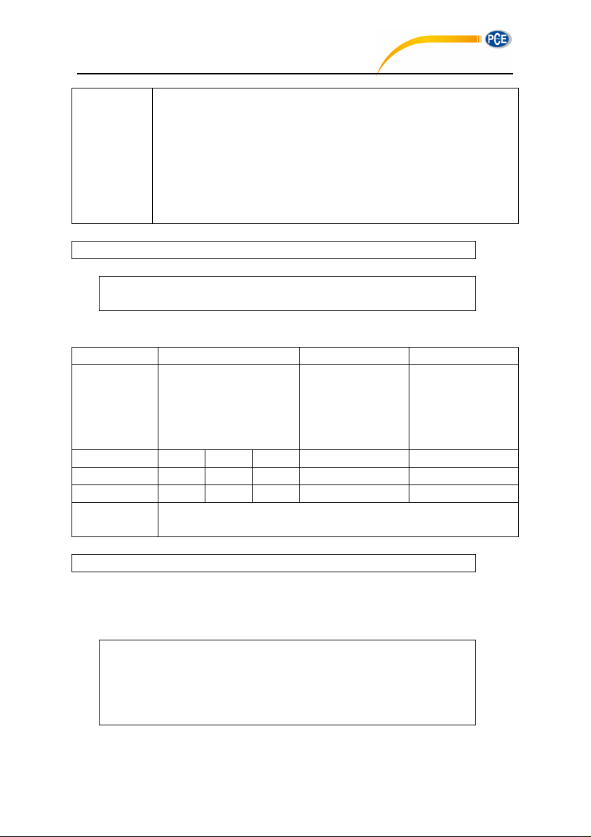
Group 3: LAe, LBe, LCe, LZe
Group4: LAFmax, LASmax, LAImax, LBFmax, LBSmax, LBImax, LCFmax,
LCSmax, LCImax, LZFmax, LZSmax, LZImax
Group 5: LAFmin, LASmin, LAImin, LBFmin, LBSmin, LBImin, LCFmin,
LCSmin, LCImin, LZFmin, LZSmin, LZImin
Group 6: LApeak, LBpeak, LCpeak, LZpeak
Group 7: LAeq, LBeq, LCeq, LZeq
Group 8: Percentage values and statistics of ten LN
Example: query group 7 (LEQ)
02 01 43 44 53 4C 37 20 31 20 3F 03 21 0D 0A
02 01 41 30 36 35 2E 30 2C 30 36 36 2E 32 2C 30 36 37 2E 30 2C 30 36 37
2E 32 03 6E 0D 0A
Instruction
P1
P2
Explanation
DOT
p1: Return manner;
0=Stop return;
1=Single return;
2=Continuous
return;
Query parameter: ?
ASCII
D
O T 1 ? Hex
44H
4FH
54H
31H
3FH
Byte
1 1 1 1 1
Return
Return 1/1 octave band data: Filter, LAeq, LBeq, LCeq, LZeq, 8Hz, 16Hz,
31.5Hz, 63Hz, 125Hz, 250Hz, 500Hz, 1kHz, 2kHz, 4kHz, 8kHz, 16kHz
02 01 43 44 4F 54 31 20 3F 03 32 0D 0A
02 01 41 31 2C 30 36 34 2E 37 2C 30 36 36 2E 30 2C 30 36 36 2E 38 2C 30
36 37 2E 31 2C 30 33 30 2E 37 2C 30 34 31 2E 36 2C 30 34 38 2E 34 2C 30
35 33 2E 39 2C 30 35 36 2E 38 2C 30 35 39 2E 35 2C 30 36 30 2E 38 2C 30
36 30 2E 33 2C 30 35 37 2E 38 2C 30 35 33 2E 36 2C 30 34 37 2E 30 2C 30
33 35 2E 34 03 7F 0D 0A
PCE-428 / 430 / 432
Returns: the LEQ data: LAeq=065.0dB, LBeq=066.2dB; LCeq=067.0dB; LZeq=067.2dB
DOT?: Query 1/1 Octave Band Data
Example: query 1/1 octave data
Returns: the current 1/1 octave band filter is C-weighting, and data are: LAeq=064.7dB,
LBeq=066.0dB, LCeq=066.8dB, LZeq=067.1dB, 8Hz=030.7dB, 16Hz=041.6dB,
31.5Hz=048.4dB, 63Hz=053.9dB, 125Hz=056.8dB, 250Hz=059.5dB, 500Hz=060.8dB,
1kHz=060.3dB, 2kHz=057.8dB, 4kHz=053.6dB, 8kHz=047.0dB, 16kHz=035.4dB
97
Page 94
DTT?: Query 1/3 Octave Band Data
Instruction
P1
P2
Explanation
DTT
p1: Return manner;
0=Stop return;
1=Single return;
2=Continuous
return;
Query parameter: ?
ASCII
D
T T 1 ? Hex
44H
54H
54H
31H
3FH
Byte
1 1 1 1 1
Return
Return 1/3 octave band data: Filter, LAeq, LBeq, LCeq, LZeq, 6.3Hz, 8Hz,
10Hz, 12.5Hz, 16Hz, 20Hz, 25Hz, 31.5Hz, 40Hz, 50Hz, 63Hz, 80Hz,
100Hz, 125Hz, 160Hz, 200Hz, 250Hz, 315Hz, 400Hz, 500Hz, 630Hz,
800Hz, 1kHz, 1.25kHz, 1.6kHz, 2kHz, 2.5kHz, 3.15kHz, 4kHz, 5kHz,
6.3kHz, 8kHz, 10kHz, 12.5kHz, 16kHz, 20kHz
02 01 43 44 54 54 31 20 3F 03 00 0D 0A
02 01 41 31 2C 30 36 34 2E 38 2C 30 36 36 2E 30 2C 30 36 36 2E 39 2C 30
36 37 2E 31 2C 30 31 37 2E 38 2C 30 32 33 2E 35 2C 30 32 38 2E 30 2C 30
33 32 2E 32 2C 30 33 35 2E 34 2C 30 33 38 2E 34 2C 30 34 31 2E 30 2C 30
34 33 2E 36 2C 30 34 35 2E 39 2C 30 34 37 2E 30 2C 30 34 38 2E 35 2C 30
34 39 2E 38 2C 30 35 30 2E 39 2C 30 35 32 2E 31 2C 30 35 33 2E 30 2C 30
35 34 2E 31 2C 30 35 34 2E 37 2C 30 35 35 2E 35 2C 30 35 35 2E 39 2C 30
35 36 2E 32 2C 30 35 36 2E 33 2C 30 35 36 2E 31 2C 30 35 35 2E 36 2C 30
35 34 2E 39 2C 30 35 34 2E 32 2C 30 35 33 2E 30 2C 30 35 31 2E 38 2C 30
35 30 2E 34 2C 30 34 38 2E 38 2C 30 34 36 2E 39 2C 30 34 34 2E 36 2C 30
34 31 2E 38 2C 30 33 38 2E 31 2C 30 33 33 2E 33 2C 30 32 36 2E 32 2C 30
31 35 2E 30 03 72 0D 0A
PCE-428 / 430 / 432
Example: query 1/3 octave band data.
Return: current Filter is C-weighting, LAeq=064.8dB, LBeq=066.0dB, LCeq=066.9dB,
LZeq=067.1dB, 6.3Hz=017.8dB, 8Hz=023.5dB, 10Hz=028.0dB, 12.5Hz=032.2dB,
16Hz=035.4dB, 20Hz=038.4dB, 25Hz=041.0dB, 31.5Hz=043.6dB, 40Hz=045.9dB,
0Hz=047.0dB, 63Hz=048.5dB, 80Hz=049.8dB, 100Hz=050.9dB, 125Hz=052.1dB,
160Hz=053.0dB, 200Hz=054.1dB, 250Hz=054.7dB, 315Hz=055.5dB, 400Hz=055.9dB,
500Hz=056.2dB, 630Hz=056.3dB, 800Hz=056.1dB, 1kHz=055.6dB, 1.25kHz=054.9dB,
1.6kHz=054.2dB, 2kHz=053.0dB, 2.5kHz=051.8dB, 3.15kHz=050.4dB, 4kHz=048.8dB,
5kHz=046.9dB, 6.3kHz=044.6dB, 8kHz=041.8dB, 10kHz=038.1dB, 12.5kHz=033.3dB,
16kHz=026.2dB, 20kHz=015.0dB
98
Page 95
CSD: Save Custom Data into MicroSD
Instruction
Parameters
Explanation
CSD
None
ASCII
C S D
None
Hex
43H
53H
44H
None
Byte
1 1 1
None
Return
Return state:
0= Stored successfully, MicroSD OK;
1= Failure to store, MicroSD error;
2=No MicroSD.
02 01 43 43 53 44 03 17 0D 0A
02 01 41 30 03 71 0D 0A
PCE-428 / 430 / 432
Example: Save CSD
Return: save successfully, MicroSD OK
99
Page 96
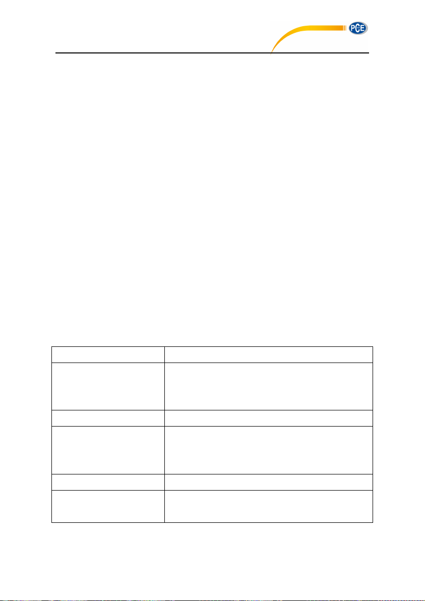
6. Operation Notes
Issue
Possible Root Cause And Solution
Boot up failure.
Low battery: replace battery;
Power adapter failure: replace power adapter;
Power button failure: please return to factory.
Inaccurate measurements.
Please try to calibrate again.
Measurement data don’t have
observable changes when
sound source changed a lot.
Damaged microphone: return microphone to factory.
Bad contact between microphone and main body:
please return the main body to factory.
Button failure.
Button was damaged: please return to factory.
Slow response when
operation.
Too much files in the MicroSD card: please delete the
trashy files.
PCE-428 / 430 / 432
6.1 Operation
Please minimize the influence of vibration when using sound level meter, mechanical
vibration could affect indicated levels at the lower boundary of the measurement range at
frequencies within the range of the sound level meter (10Hz~20kHz).
Sound level meter need at least 6 hours to reach equilibrium with the ambient
environment before switching on the power. After the equilibrium process and switching
on the power, no initial time need before sound level meter measure the level of sound.
The measurement microphone is a sensitive component, please use it careful. Store the
microphone in the attached box which can protect it against damage from outside.
Please follow the introduction and using step in the user manual. Do not drop, knock or
shake the product. Any operation over the limit could damage the product.
Keep out the water and any other liquid due to no waterproof design on this product.
Using qualified alkaline battery can extend your operation time and bring benefit to device.
Do not mix using of old and new batteries at the same time. Remove batteries when the
device is not in use. Long-term place the battery inside the product could cause battery
leakage and damage to the product.
6.2 Common Issue And Solutions
100
Page 97

Can’t save the measurement
data.
Check logger settings.
Format SD to FAT32.
Replace new MicroSD card with maximum capacity 4G.
The Printer can’t print the
measurement data.
Check the settings related to printer.
Make sure the print-paper is installed correctly.
6.3 Calibration
PCE-428 / 430 / 432
Sound level meter has been calibrated before sales. Keep regular calibration can ensure the
accuracy of the measurement. PCE Instruments provide the calibration service for acoustic products.
6.4 Firmware Update
3&( firmware can be update via USB port. Following items need to be prepared:
PCE-428/430/432 sound level meter (HWID: P0274 or above) and keep power off;
MiniUSB cable (include in sales package);
External power supply (include in sales package);
Firmware for update (download from PCE Instruments website);
USB driver (Silicon Labs CP210x driver), can be find in CD-ROM or PCE Instruments website;
Firmware update tool: FlashTool Wizard, can be find in CD-ROM or PCE Instruments website.
6.4.1 Install USB Driver
Unzip and install driver step by step.
Note that select X86 for 32-bit OS and
select X64 for 64-bit OS.
☆Note: Do not connect sound level
meter to computer when install driver.
Follow the prompt to install, accept the
license agreement and then click next
until the driver installation is complete.
101
Page 98
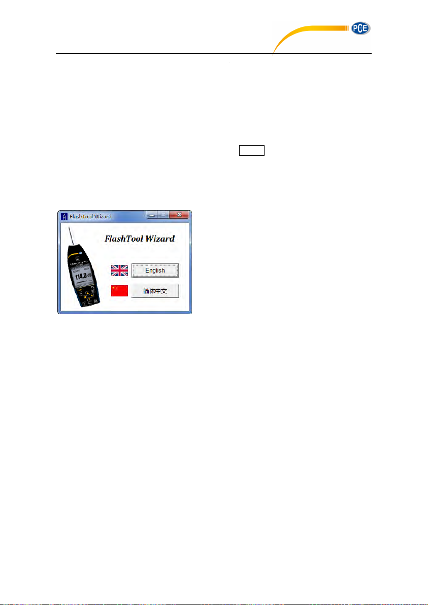
6.4.2 Firmware Update Procedure
PCE-428 / 430 / 432
After driver installation, connect sound
level meter to computer via USB cable,
a new device named Silicon Labs
CP210x USB to UART Bridge (COMx)
could be found in Device Manager.
☆Note: Power sound level meter by
external supply when connect to
computer.
The firmware update software FlashTool Wizard is
very easy to use. Please just follow the prompt
step by step.
Run FlashTool Wizard and select language.
Step 1: prepare the list items for update firmware.
Step 2: Install the driver. Please skip if you already
install deriver before.
102
Page 99

Step 3: Connect sound level meter and computer
PCE-428 / 430 / 432
according to the prompt. Note that sound level
meter needs external power supply. If driver is
working properly, it will automatically select Port of
CP210x. The default value of Baudrate is 115200,
which relate to the computer. Higher Baudrate can
fast the update procedure.
Step 4: first press the button located on the top
right corner to select firmware, and then
press Update button to start. The whole procedure
need 3~4 minutes.
☆ Note: Reset to factory settings and run
calibration at least one time after firmware update,
otherwise sound level meter may note work
properly. If always display “Time Out!”, remove MicroSD card and try again.
There is no limitation for firmware to upgrade or downgrade, so user can update to any
version. Hence, we advise to keep the latest version of firmware. Please no hesitate to
contact us by phone call or e-mail to request support for any issue or bugs of firmware.
☆Note: Firmware update is a feature only available for new sound level meter with HWID:
P0274 or above. The old type of HWID: P0115 cannot update firmware by user. Following list
the difference between old type and new type:
In About page, P0115 displays type PCE-428/430/432, while P0274 displays type 308S/309S.
RS-232 port of P0115 using Lemo 3-pin socket, while P0274 using PS/2 6-pin socket.
P0115 USB port is unavailable in function, while P0274 USB function is available.
P0115 has two measurement ranges: High and Low, some early product also has Auto
range, while P0274 has only one range.
6.5 Warranty
PCE Instruments can provide warranty service during the warranty period. The component could be
replaced according to the determination of PCE Instruments to solve the issue caused by materials,
design or manufacture.
103
Page 100

Annex 1 Glossary
PCE-428 / 430 / 432
Frequency Weighting1: Difference, as a specified function of frequency, between the
level of the frequency weighted signal indicated on the display device and the
corresponding level of a constant amplitude sinusoidal input signal. Level difference is
expressed in decibels (dB). Frequency weighting usually have A, B, C and D-weighting,
which can simulate the response of human hearing. The A and C-weighting are more
commonly used and defined in IEC and GB/T standard. B-weighting is only defined in
ANSI standard. D-weighting related international standard is already withdrawn. Only
some old type instrument has D-weighting. No frequency weighting or to say flat response
always named as Z-weighting, Flat or Linear.
Time Weighting1: Exponential function of time, of a specified time constant, that weights
the square of a sound pressure signal. The weighting of sound pressure is more higher if
it closer to the current time, and vice versa. Time weighting Fast and Slow are more
commonly used, while Impulse is not recommended to use and was reserved only for
historical reasons.
SPL: Sound pressure level, SPL calculated in sound level meter is the greatest time
weighted sound level within 1 second.
LEQ1: Time averaged sound level or equivalent continuous sound level. Ten times the
logarithm to the base 10 of the ratio of the time average of the square of a frequency
weighted sound pressure signal during a stated time interval to the square of the
reference value. The LEQ is actually integral value of sound level within stated duration.
The longer the integration period, the slower LEQ changes. LEQ is widely used in the
noise overall evaluation.
Peak1: Peak sound level. Ten times the logarithm to the base 10 of the ratio of the square
of a frequency weighted peak sound pressure signal to the square of the reference value.
It’s usually used to evaluate the very short pulse of noise.
E1: Sound exposure. Time integral of the square of a frequency weighted sound pressure
signal over a stated time interval or event of stated duration. It’s always used to evaluate
the impact of noise to human being.
105
 Loading...