

Page 1

PCA-6005
Full-sized PCI-bus
socket 478 Pentium 4/Celeron
processor-based CPU card
User’s Manual
Page 2

PCA-6005 User’s Manual ii
Page 3

Copyright
This document is copyrighted, 2002. All rights are reserved. The original
manufacturer reserves the right to make improvements to the products
described in this manual at any time without notice.
No part of this manual may be reproduced, copied, translated or transmitted in any form or by any means without the prior written permission of
the original manufacturer. Information provided in this manual is
intended to be accurate and reliable. However, the original manufacturer
assumes no responsibility for its use, nor for any infringements upon the
rights of third parties that may result from such use.
Acknowledgements
AWARD is a trademark of AWARD Software, Inc.
IBM and PC are trademarks of International Business Machines Corporation.
Intel® and Pentium® 4 are trademarks of Intel Corporation.
Windows is a trademark of Microsoft Corporation.
ITE is a trademark of Integrated Technology Express, INC.
SiS is a registered trademark of Silicon Integrated Systems Corp.
Realtek is a trademark of Realtek Semiconductor Corporation
All other product names or trademarks are properties of their respective
owners.
Part No. 2002600501 2nd. Edition
Printed in Taiwan October 2002
iii
Page 4

A Message to the Customers
Advantech customer services
Each and every Advantech product is built to the most exacting specifications to ensure reliable performance in the harsh and demanding conditions typical of industrial environments. Whether your new Advantech
equipment is destined for the laboratory or the factory floor, you can be
assured that your product will provide the reliability and ease of operation
for which the name Advantech has come to be known. Your satisfaction
is our primary concern. Here is a guide to Advantech.s customer services.
To ensure you get the full benefit of our services, please follow the
instructions below carefully.
Technical support
We want you to get the maximum performance from your products. So if
you run into technical difficulties, we are here to help. For the most frequently asked questions, you can easily find answers in your product documentation. These answers are normally a lot more detailed than the ones
we can give over the phone. So please consult this manual first. If you
still cannot find the answer, gather all the information or questions that
apply to your problem, and with the product close at hand, call your
dealer. Our dealers are well trained and ready to give you the support you
need to get the most from your Advantech products. In fact, most problems reported are minor and are able to be easily solved over the phone.
In addition, free technical support is available from Advantech engineers
every business day. We are always ready to give advice on application
requirements or specific information on the installation and operation of
any of our products.
PCA-6005 User’s Manual iv
Page 5

PCA-6005F-00A1
V
Dual
V
X
PCA-6005E2--0EA1
PCA-6005VE-00A1
PCA-6005V-00A1
PCA-6005 Comparison Table
Model
V
V
V
VGA (AGP 4X):
SiS650 chipset integrated
Dual
Single
X
LAN: 10/100 Base-T, RTL8139C
X
X
X
SCSI: Adaptec 7899 U160 SCSI
X
X
X
ISA Bus
v
Page 6

PCA-6005 User’s Manual vi
Page 7

Product warranty
Advantech warrants to you, the original purchaser, that each of its products will be free from defects in materials and workmanship for two years
from the date of purchase. This warranty does not apply to any products
which have been repaired or altered by persons other than repair personnel authorized by Advantech, or which have been subject to misuse,
abuse, accident or improper installation. Advantech assumes no liability
under the terms of this warranty as a consequence of such events. If an
Advantech product is defective, it will be repaired or replaced at no
charge during the warranty period. For out-of-warranty repairs, you will
be billed according to the cost of replacement materials, service time and
freight. Please consult your dealer for more details. If you think you have
a defective product, follow these steps:
1. Collect all the information about the problem encountered. (For example, type of PC, CPU speed, Advantech products used, other hardware
and software used, etc.) Note anything abnormal and list any on-screen
messages you get when the problem occurs.
2. Call your dealer and describe the problem. Please have your manual,
product, and any helpful information readily available.
3. If your product is diagnosed as defective, obtain an RMA (return material authorization) number from your dealer. This allows us to process
your return more quickly.
4. Carefully pack the defective product, a fully-completed Repair and
Replacement Order Card and a photocopy proof of purchase date (such as
your sales receipt) in a shippable container. A product returned without
proof of the purchase date is not eligible for warranty service.
5. Write the RMA number visibly on the outside of the package and ship
it prepaid to your dealer
vii
Page 8

Initial Inspection
Before you begin installing your card, please make sure that the following
materials have been shipped:
. 1 PCA-6005 pure PCI single board computer
. 1 Pentium 4 processor (optional)
. 1 PCA-6005 startup Manual
. 1 CD driver utility and manual (in PDF format)
. 1 FDD cable, P/N: 1701340703
. 2 UDMA 66/100 HDD cables, P/N: 1701400452
. 1 printer (parallel port) cable & COM port cable kit, P/N: 1700060305
. 1 ivory cable for PS/2 keyboard and PS/2 mouse, P/N: 1700060202
. 1 USB cable (optional), P/N 1700100170
. 1 single-slot bracket (optional), P/N: 1962159010
If any of these items are missing or damaged, contact your distributor or
sales representative immediately. We have carefully inspected the PCA6005 mechanically and electrically before shipment. It should be free of
marks and scratches and in perfect working order upon receipt. As you
unpack the PCA-6005, check it for signs of shipping damage. (For example, damaged box, scratches, dents, etc.) If it is damaged or it fails to meet
the specifications, notify our service department or your local sales representative immediately. Also notify the carrier. Retain the shipping carton
and packing material for inspection by the carrier. After inspection, we
will make arrangements to repair or replace the unit
PCA-6005 User’s Manual viii
Page 9

Contents
Chapter 1 General Information ........................................2
1.1 Introduction ....................................................................... 2
1.2 Features ............................................................................. 3
1.3 General Specifications....................................................... 4
1.3.1 System............................................................................. 4
1.3.2 Memory........................................................................... 4
1.3.3 Input/Output.................................................................... 4
1.3.4 VGA interface................................................................. 4
1.3.5 Ethernet LAN.................................................................. 5
1.3.6 Ultra 160 SCSI................................................................ 5
1.3.7 Industrial features ........................................................... 5
1.3.8 Mechanical and environmental specifications ................ 5
1.4 Jumpers and Connectors.................................................... 5
Table 1.1:Jumpers ........................................................... 5
Table 1.2:Connectors...................................................... 6
Table 1.3:SCSI Daughter board:..................................... 7
1.5 Board Layout: Jumper and Connector Locations.............. 8
1.6 Safety Precautions ........................................................... 10
1.7 Jumper Settings ............................................................... 10
1.7.1 How to set jumpers ....................................................... 10
1.7.2 CMOS clear (J1) ........................................................... 11
Table 1.4:CMOS clear (J1) ........................................... 11
1.7.3 Watchdog timer output (J2) .......................................... 11
Table 1.5:Watchdog timer output (J2).......................... 11
1.8 System Memory .............................................................. 12
Table 1.6:DIMM module allocation table .................... 12
1.8.1 Supplementary information about DIMMs................... 12
1.8.2 Memory clock setting ................................................... 12
1.9 Memory Installation Procedures ..................................... 13
1.10 Cache Memory ................................................................ 13
1.11 CPU Installation .............................................................. 13
Chapter 2 Connecting Peripherals .................................16
2.1 Primary (CN1) and Secondary (CN2) IDE Connectors. . 16
2.2 Floppy Drive Connector (CN3).................................... 17
2.3 Parallel Port (CN4).......................................................... 17
2.4 USB Port (CN6) .............................................................. 18
2.5 VGA Connector (CN7) ................................................... 18
2.6 10/100Base-T Ethernet Connector (CN8 and CN34) .. 19
2.7 Serial Ports (CN9: COM1; CN10: COM2)................ 20
2.8 PS/2 Keyboard and Mouse Connector
(CN11 and CN33) ........................................................... 21
2.9 External Keyboard Connector (CN12)......................... 21
1
Page 10

2.10 CPU Fan Connector (CN14) ........................................... 22
2.11 Front Panel Connectors (CN16, CN17, CN18, CN19,
CN21 and CN29)............................................................ 22
2.11.1 Keyboard lock and power LED (CN16) ....................... 22
2.11.2 External speaker (CN17) .............................................. 23
2.11.3 Reset (CN18) ................................................................ 23
2.11.4 HDD LED (CN19)........................................................ 23
2.11.5 SM Bus Connector (CN29)........................................... 23
2.11.6 Connecting to SNMP-1000 remote manager................ 24
2.12 ATX Power Control Connectors (CN20 and CN21) .. 24
2.12.1 ATX feature connector (CN20) and soft power switch
connector (CN21) ........................................................ 24
2.12.2 Controlling the soft power switch................................ 25
2.13 Auxiliary power input (CN46 & ATX1)......................... 25
Chapter 3 Award BIOS Setup.........................................28
3.1 Introduction ..................................................................... 28
3.2 Entering Setup................................................................. 28
Figure 3.1:Award BIOS Setup initial screen ................ 28
3.3 Standard CMOS Setup .................................................... 29
3.3.1 CMOS RAM backup .................................................... 29
3.4 Advanced BIOS Features................................................ 30
Figure 3.2:Advanced BIOS features screen.................. 30
3.4.1 Virus Warning............................................................... 30
3.4.2 CPU L1 & L2 Cache..................................................... 30
3.4.3 CPU L2 Cache ECC Checking ..................................... 30
3.4.4 First/Second/Third/Other Boot Device ......................... 31
3.4.5 Swap Floppy Drive ....................................................... 31
3.4.6 Boot UP Floppy Seek ................................................... 31
3.4.7 Boot Up NumLock Status............................................. 31
3.4.8 Gate A20 Option ........................................................... 31
3.4.9 Typematic Rate Setting................................................. 31
3.4.10 Typematic Rate (Chars/Sec) ......................................... 31
3.4.11 Typematic Delay (msec) ............................................... 31
3.4.12 Security Option ............................................................. 31
3.4.13 OS Select for DRAM > 64MB ..................................... 32
3.4.14 Video BIOS Shadow..................................................... 32
3.5 Advanced Chipset Features............................................. 33
Figure 3.3:Advanced chipset features screen ............... 33
3.5.1 Advanced DRAM control 1 .......................................... 34
3.5.2 Prefetch Caching........................................................... 34
3.5.3 System BIOS Cacheable ............................................... 34
3.5.4 Memory Hole ................................................................ 35
3.5.5 AGP Aperture Size ....................................................... 35
PCA-6005 User’s Manual 2
Page 11

3.6 Integrated Peripherals...................................................... 35
Figure 3.4:Integrated peripherals .................................. 35
3.6.1 SiS OnChip IDE Device ............................................... 36
3.6.2 SiS OnChip PCI Device................................................ 37
3.6.3 Onboard Super IO Device............................................. 38
3.6.4 USB controller .............................................................. 39
3.6.5 USB Keyboard Support ................................................ 39
3.6.6 USB Mouse Support ..................................................... 39
3.6.7 IDE HDD Block Mode ................................................. 39
3.6.8 Onboard Lan Boot Rom................................................ 39
3.6.9 Init Display First ........................................................... 39
3.7 Power Management Setup............................................... 40
Figure 3.5:Power management setup screen................. 40
3.7.1 ACPI function ............................................................... 40
3.7.2 Power Management ...................................................... 40
3.7.3 Video Off Option .......................................................... 41
3.7.4 Video Off Method......................................................... 41
3.7.5 MODEM Use IRQ ........................................................ 41
3.7.6 Soft-Off by PWRBTN .................................................. 41
3.7.7 Power-Supply Type ...................................................... 41
3.7.8 Power State Resume Control ........................................ 42
3.7.9 PM Wake Up Events..................................................... 42
Figure 3.6:Wake Up Events.......................................... 42
3.8 PnP/PCI Configurations .................................................. 43
3.8.1 Reset Configuration Data.............................................. 43
3.9 PC Health Status.............................................................. 44
Figure 3.8:PC health status screen ................................ 44
3.9.1 Current CPU Temperature ............................................ 44
3.9.2 Current CPUFAN Speed............................................... 44
3.9.3 VCORE ......................................................................... 44
3.10 Load Optomized Defaults ............................................... 44
3.11 Set Password ................................................................... 45
3.12 Save & Exit Setup ........................................................... 45
3.13 Exit Without Saving ........................................................ 45
Chapter 4 AGP SVGA Setup ..........................................48
4.1 Before You Begin............................................................ 48
4.2 Features ........................................................................... 48
4.3 VGA Installation ............................................................. 49
Chapter 5 LAN Configuration ........................................52
5.1 Introduction ..................................................................... 52
5.2 Features ........................................................................... 52
5.3 Driver Installation ........................................................... 53
5.4 Windows 9X Drivers Setup Procedure ........................... 54
3
Page 12

5.5 Windows NT Drivers Setup Procedure........................... 60
5.6 Windows 2000 Drivers Setup Procedure ........................ 65
Chapter 6 SCSI Setup and Configuration .....................72
6.1 Introduction ..................................................................... 72
6.2 Understanding SCSI....................................................... 72
6.3 SCSI IDs.......................................................................... 73
6.4 Terminating the SCSI Bus............................................ 74
6.5 Configuring the SCSI interface with SCSISelect............ 75
6.6 Starting SCSISelect ........................................................ 77
6.7 Using SCSI Disk Utilities ............................................... 81
6.8 Installation under Windows NT/Windows 2000............ 82
6.9 Windows 9X Driver setup procedure.......................... 82
6.10 Windows NT Driver Setup Procedure ........................ 87
Appendix A Programming the watchdog..........................92
A.1 Programming the watchdog ............................................ 92
A.1.1 Watchdog timer overview............................................. 92
A.1.2 Programming the Watchdog Timer .............................. 92
A.1.3 Unlock the Super I/O IT8705F ..................................... 92
A.1.4 Select and program the watchdog timer ....................... 92
A.1.5 Select and enable the game port ................................... 92
A.1.6 Lock the Super I/O IT8705F......................................... 93
A.1.7 Resetting the Watchdog Timer ..................................... 93
A.1.8 List of Registers ............................................................ 94
Appendix B Pin Assignments ...........................................102
B.1 IDE Hard Drive Connector (CN1, CN2)....................... 102
B.2 Floppy Drive Connector (CN3)..................................... 103
B.3 Parallel Port Connector (CN4) ...................................... 104
B.4 USB Connector (CN6) ................................................. 105
B.5 VGA Connector (CN7) ................................................. 106
B.6 Keyboard and Mouse Connnector CN11)..................... 107
B.7 External Keyboard Connector (CN12).......................... 107
B.8 IR Connector (CN13) .................................................... 108
B.9 CPU Fan Power Connector (CN14).............................. 108
B.10 Power LED (CN16)....................................................... 109
B.11 External Speaker Connector (CN17)............................. 109
B.12 Reset Connector (CN18) ............................................... 110
B.13 HDD LED Connector (CN19)....................................... 110
B.14 ATX Feature Connector (CN20)................................... 111
B.15 ATX Soft Power Switch (CN21) .................................. 111
B.16 SM Bus Connector (CN29) ........................................... 112
B.17 System I/O Ports............................................................ 112
PCA-6005 User’s Manual 4
Page 13

B.18 DMA Channel Assignments.......................................... 114
B.19 Interrupt Assignments ................................................... 114
B.20 1st MB Memory Map.................................................... 115
B.21 PCI Bus Map ................................................................. 115
5
Page 14

PCA-6005 User’s Manual 6
Page 15

CHAPTER
General Information
This chapter gives background information on the PCA-6005. It then shows
you how to configure the card to match
your application and prepare it for
installation into your PC.
Sections include:
• Introduction
• Features
• Specifications
• Board Layout
• Jumpers and Connectors
• Safety Precautions
• Jumper Settings
• System Memory
• Memory Installation Procedures
• Cache Memory
• CPU Installation
1
1
Page 16

Chapter 1 General Information
1.1 Introduction
The PCA-6005 Series all-in-one industrial grade single board computer is
a high performance and full-featured computing engine. It meets most of
the requirements of industrial applications.
The PCA-6005 supports Intel's Pentium 4 and Socket 478 Celeron processor. The CPU provides 256/512 KB on-CPU L2 cache, featuring
Intel's NetBurst. micro-architecture and is capable of delivering maximum computing power. It has two PCI EIDE interfaces (for up to four
devices) and a floppy disk drive interface (for up to two devices). Other
features include two RS-232 serial ports (16C550 UARTs with 16-byte
FIFO or compatible), one enhanced parallel port (supports EPP/ECP) and
two USB (Universal Serial Bus) ports. The PCI enhanced IDE controller
supports Ultra DMA/33/66/100 providing data transfer rates of 33/66/100
MB/sec. System BIOS supports boot-up from an IDE CD-ROM, SCSI
CD-ROM, LS-120, IDE HDD, SCSI HDD, ZIP-100, LAN, and FDD.
A backup of CMOS data is stored in the Flash memory, which protects
data even after a battery failure. Also included is a 256-level watchdog
timer, which resets the CPU or if a program cannot be executed normally.
This enables reliable operation in unattended environments.
The PCA-6005 Series offers several impressive industrial features such as
chipset built-in VGA (AGP) interface, dual 10/100Base-T networking
controller, dual channel Ultra 160 SCSI, and two 184-pin DIMM slots for
a total of 2 GB DDR SDRAM memory. The remote management interface enables the PCA-6005 to be managed through Ethernet when it is
connected to the SNMP-1000 Remote HTTP/SNMP System Manager.
NOTE: 1. The PCA-6005 does not support ISA bus.
2. Some of the features mentioned above are
not available with all models. For more information about the specifications of a particular
model, see Section 1.3: Specifications.
PCA-6005 User’s Manual 2
Page 17

1.2 Features
1. Onboard hardware monitoring: System healthy status including
CPU fan, CPU temperature and system voltages levels are monitored to ensure stable operation. proper system configuration and
management. A remote monitoring interface is reserved for remote
management through Ethernet by using Advantech's SNMP-1000
system management module.
2. ATX soft power switch: Through the BIOS, the power button can
be defined as the "Standby" (aka "Suspend" or "Sleep") button or as
the "Soft-Off" button. Regardless of the setting, pushing the power
button for more than 4 seconds will enter the Soft-Off mode.
3. Power-on by modem (requires modem): This allows a computer
to be turned on remotely through an internal or external modem.
Users can thus access information on their computers from anywhere in the world.
4. Power-on by LAN: This allows you to remotely power up your
system through your network by sending a wake-up frame or signal. With this feature, you can remotely upload/ download data to/
from systems during off-peak hours.
5. CMOS RAM backup: When BIOS CMOS setup has been completed, data in the CMOS RAM is automatically backed up to the
Flash ROM. This is particularly useful in industrial environments
which may cause soft errors. Upon such an error, BIOS will check
the data and automatically restore the original data for rebooting.
3
Page 18

1.3 General Specifications
1.3.1 System
• CPU: Intel socket 478 Celeron® 1.7 GHz and above, Pentium® 4
1.8 GHz and above, FSB 400/533 MHz
• BIOS: Award Flash BIOS, 2 Mb
• System Chipset: SiS 650/651
• Enhanced IDE hard disk drive interface: Supports up to four IDE
large hard disk drives or other enhanced IDE devices. Supports PIO
mode 4 (16.67 MB/s data transfer rate) and Ultra DMA/33/66/100 (33/
66/100 MB/s data transfer rate). BIOS enabled/disabled
• Floppy disk drive interface: Supports up to two floppy disk drives,
5º" (360 KB and 1.2 MB) and/or 3¾" (720 KB, 1.44 MB, and 2.88
MB). BIOS enabled/disabled
1.3.2 Memory
• RAM: Up to 2 GB in two available 184-pin DIMM sockets. Supports
PC-200/ PC-266-compliant DDR SDRAM
• No ECC support
1.3.3 Input/Output
• Bus interface: PCI bus only, mechanically compliant with PICMG
• Enhanced parallel port: Configurable to LPT1, LPT2, LPT3, or dis-
abled. Standard DB-25 female connector provided. Supports EPP/ECP
• Serial ports: Two RS-232 ports with 16C550 UARTs (or compatible)
with 16-byte FIFO buffer. Supports speeds up to 115.2 Kbps. Ports can
be individually configured to COM1, COM2 or disabled
• Keyboard and PS/2 mouse connector: A 6-pin mini-DIN connector is
located on the mounting bracket for easy connection to a keyboard or
PS/2 mouse. An onboard keyboard pin header connector is also available
• ISA bus: No ISA bus support
1.3.4 VGA interface
• Controller: SiS 650/651 chipset integrated, AGP 4X
• Display memory: Share system memory up to 64 MB, BIOS selectable
• Resolution up to 2048x1536 16M colors
PCA-6005 User’s Manual 4
Page 19

1.3.5 Ethernet LAN
• Supports dual 10/100Base-T Ethernet networking
• Chipset: Realtek 8139C
1.3.6 Ultra 160 SCSI
• Provides dual channel Ultra 160 SCSI interface
• Chipset: Adaptec AIC7899
1.3.7 Industrial features
• Watchdog timer: Can generate a system reset or IRQ11. The watchdog
timer is programmable, with each unit equal to one second or one
minute (255 levels). You can find programming detail in Appendix A.
1.3.8 Mechanical and environmental specifications
• Operating temperature: 0 ~ 60° C (32 ~ 140° F), depending on CPU
• Storage temperature: -20 ~ 70° C (-4 ~ 158°F)
• Humidity: 20 ~ 95% non-condensing
• Power supply voltage: ±5 V, ±12 V
• Power consumption: +5 V @ 2.3 A, +12V @ 3.3 A (typical, with Pen-
tium 4 1.6 GHz and 512 MB DDR266 SDRAM)
• Board size: 338 x 122 mm (13.3" x 4.8")
• Board weight: 0.6 kg (1.2 lb)
1.4 Jumpers and Connectors
Connectors on the PCA-6005 board link it to external devices such as
hard disk drives and a keyboard. In addition, the board has a number of
jumpers used to configure your system for your application. The tables
below list the function of each of the board jumpers and connectors. Later
sections in this chapter give instructions on setting jumpers. Chapter 2
gives instructions for connecting external devices to your card.
Table 1.1: Jumpers
Label Function
J1 CMOS clear
J2 Watchdog timer output
5
Page 20

Table 1.2: Connectors
Label Function
CN1 Primary IDE connector
CN2 Secondary IDE connector
CN3 Floppy drive connector
CN4 Parallel port
CN6 USB port
CN7 VGA connector
CN8 10/100Base-T Ethernet connector
CN9 Serial port: COM1
CN10 Serial port: COM2
CN11 PS/2 keyboard and mouse connector
CN12 External keyboard connector
CN13 Infrared (IR) connector
CN14 CPU fan connector
CN16 Power LED
CN17 External speaker
CN18 Reset connector
CN19 HDD LED connector
CN20 ATX feature connector
CN21 ATX soft power switch
CN27 Extension I/O board connector
CN28 Extension I/O board connector
CN29 External SM bus connector
CN30 External PCI extension connector
CN33 PS/2 mouse connector
CN34 10/100Base-T Ethernet connector 2
CN43 AC-97 audio extension interface
CN46 Auxiliary power input
ATX1 ATX12V auxiliary power input
PCA-6005 User’s Manual 6
Page 21

Table 1.3: SCSI Daughter board:
CN50 68-pin U160 SCSI connector
CN51 68-pin U 160 wide SCSI Connector
CN52 50-pin Ultra Wide SCSI Connector
7
Page 22
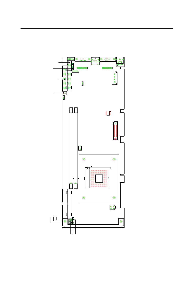
1.5 Board Layout: Jumper and Connector Locations
CN 9
CN 6
CN 10
CN 13
CN 3
CN20
CN 4
J2
DIMM1
CN 27
CN 43
J1
DIMM2
CN 14
CN 7
CN 8
CN 28
CN 11
CN 12
CN 46
S1
CN 30
CN2
CN1
CN18
CN29
CN21
CN 19
CN 17
CN 16
Figure 1.1: Board Layout: Jumper and Connector Locations
PCA-6005 User’s Manual 8
ATX1
Page 23
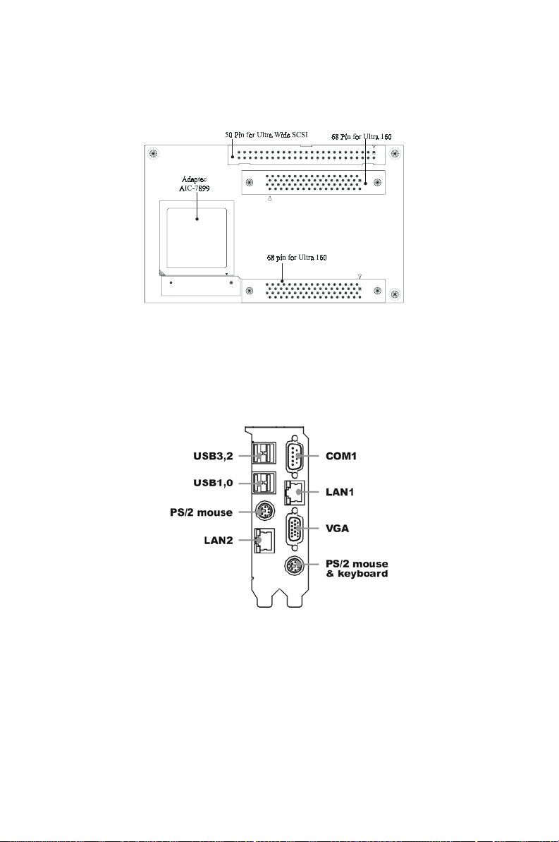
Figure 1.2: SCSI daughter board layout
Figure 1.3: I/O connectors on bracket
9
Page 24

1.6 Safety Precautions
Warning! Always completely disconnect the power cord
from your chassis whenever you work with the
hardware. Do not make connections while the
power is on. Sensitive electronic components
can be damaged by sudden power surges. Only
experienced electronics personnel should open
the PC chassis.
Caution! Always ground yourself to remove any static
charge before touching the CPU card. Modern
electronic devices are very sensitive to static
electric charges. As a safety precaution, use a
grounding wrist strap at all times. Place all electronic components in a static-dissipative surface or static-shielded bag when they are not in
the chassis.
1.7 Jumper Settings
This section provides instructions on how to configure your card by setting jumpers. It also includes the card's default settings and your options
for each jumper.
1.7.1 How to set jumpers
You configure your card to match the needs of your application by setting
jumpers. A jumper is a metal bridge that closes an electrical circuit. It
consists of two metal pins and a small metal clip (often protected by a
plastic cover) that slides over the pins to connect them. To “close” (or
turn ON) a jumper, you connect the pins with the clip. To “open” (or turn
OFF) a jumper, you remove the clip. Sometimes a jumper consists of a set
of three pins, labeled 1, 2, and 3. In this case you connect either pins 1
and 2, or 2 and 3.
A pair of needle-nose pliers may be useful when setting jumpers.
PCA-6005 User’s Manual 10
Page 25

1.7.2 CMOS clear (J1)
The PCA-6005 CPU card contains a jumper that can erase CMOS data
and reset the system BIOS information. Normally this jumper should be
set with pins 1-2 closed. If you want to reset the CMOS data, set J1 to 2-3
closed for just a few seconds, and then move the jumper back to 1-2
closed. This procedure will reset the CMOS to its default setting.
Table 1.4: CMOS clear (J1)
Function Jumper Setting
* Keep CMOS data 1-2 closed
Clear CMOS data 2-3 closed
* default setting
1.7.3 Watchdog timer output (J2)
The PCA-6005 contains a watchdog timer that will reset in case the software fails to reset the watchdog timer. The J2 jumper settings control the
outcome of what the computer will do in the event the watchdog timer is
tripped.
Table 1.5: Watchdog timer output (J2)
Jumper Setting Function
IRQ11 1-2 closed No Function
2-3 closed * Reset
* default setting
11
Page 26

1.8 System Memory
The PCA-6005 has two sockets for 184-pin dual inline memory modules
(DIMMs). All these sockets use 2.5 V unbuffered double data rate synchronous DRAMs (DDR SDRAM). are available in capacities of 128,
256, 512 and 1024 MB. The sockets can be filled in any combination with
DIMMs of any size, giving a total memory size between 128 MB and 2
GB. Use the following table to calculate the total DRAM memory within
your computer:
Table 1.6: DIMM module allocation table
Socket Number 184-pin DIMM memory
1 (128, 256, 512 or 1024 MB)
2 (128, 256, 512 or 1024 MB)
1.8.1 Supplementary information about DIMMs
Your PCA-6005 can accept DDR SDRAM memory chips without parity.
Also note:
• The PCA-6005 accpets PC-1600 (DDR200) or PC-2100 (DDR266)
DDR SDRAM, which can provide twice the performance than the PC133 SDRAM. The 168-pin SDRAM cannot be used.
• The PCA-6005 does not support ECC (error checking and correction).
Memory modules with 9 SDRAM chips/side support ECC; modules
with 8 chips/side do not support ECC.
1.8.2 Memory clock setting
The S1 dip switch is used to set the memory clock speed. If you are using
200 MHz DDR module, set S1 to OFF. If you are using 266 MHz DDR
module, set S1 to ON. S0 must be set at ON all the time.
PCA-6005 User’s Manual 12
Page 27

1.9 Memory Installation Procedures
To install DIMMs, first make sure the two handles of the DIMM socket
are in the "open" position. i.e. The handles lean outward. Slowly slide the
DIMM module along the plastic guides on both ends of the socket. Then
press the DIMM module right down into the socket, until you hear a
click. This is when the two handles have automatically locked the memory module into the correct position of the DIMM socket. To remove the
memory module, just push both handles outward, and the memory module will be ejected by the mechanism in the socket.
1.10 Cache Memory
Since the second level (L2) cache has been embedded into the Intel®
Pentium 4/Celeron processor, you do not have to take care of either
SRAM chips or SRAM modules. The built-in second level cache in the
processor yields much higher performance than the external cache memories. The cache size in the Intel® Pentium 4 processor is 256 KB or 512
KB, for Celeron® processor is 256 KB.
1.11 CPU Installation
The CPU on the board must have a fan or heat sink attached, to prevent
overheating.
Warning: Without a fan or heat sink, the CPU will over-
heat and cause damage to both the CPU and
the motherboard. To install a CPU, first turn off
your system and remove its cover. Locate the
processor socket 478.
1. Make sure the socket 478 lever is in the upright position. To raise
the lever, pull it out to the side a little and raise it as far as it will go.
2. Place the CPU in the empty socket. Follow the instructions that
came with the CPU. If you have no instructions, complete the following procedure. Carefully align the CPU so it is parallel to the
socket and the notches on the corners of the CPU correspond with
the notches on the inside of the socket. Gently slide the CPU in. It
should insert easily. If it does not insert easily, pull the lever up a
little bit more.
13
Page 28

1. Press the lever down. The plate will slide forward. You will feel
some resistance as the pressure starts to secure the CPU in the
socket. This is normal and will not damage the CPU. When the
CPU is installed, the lever should snap into place at the side of the
socket.
Note: To remove a CPU, pull the lever out to the side
a little and raise it as far as it will go. Lift out the
CPU.
PCA-6005 User’s Manual 14
Page 29

Connecting
Peripherals
This chapter tells how to connect
peripherals, switches and indicators to
the PCA-6005 board. You can access
most of the connectors from the top of
the board while it is installed in the
chassis. If you have a number of cards
installed, or your chassis is very tight,
you may need to partially remove the
card to make all the connections.
CHAPTER
2
15
Page 30
Chapter 2 Connecting Peripherals
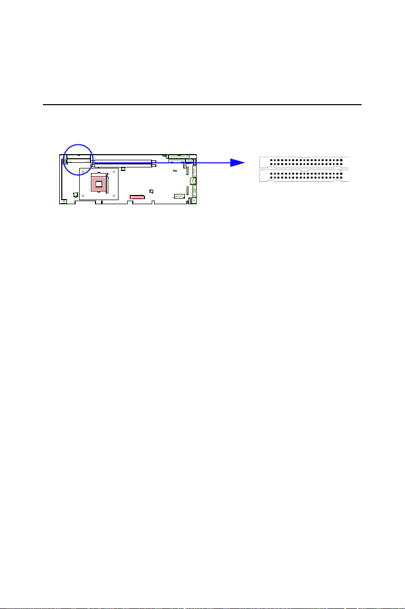
2.1 Primary (CN1) and Secondary (CN2) IDE Connectors.
CN1
CN2
You can attach up to four IDE (Integrated Device Electronics) drives to
the IDE connectors. The primary (CN1) and secondary (CN2) connectors
can each accommodate two drives.
Wire number 1 on the cable is red or blue and the other wires are gray.
Connect one end to connector CN1 or CN2 on the CPU card. Make sure
that the red/blue wire corresponds to pin 1 on the connector (in the upper
right hand corner). See Chapter 1 for help finding the connector.
Unlike floppy drives, IDE hard drives can connect in either position on
the cable. If you install two drives to a single connector, you will need to
set one as the master and one as the slave. You do this by setting the
jumpers on the drives. If you use just one drive per connector, you should
set each drive as the master. See the documentation that came with your
drive for more information.
Connect the first hard drive to the other end of the cable. Wire 1 on the
cable should also connect to pin 1 on the hard drive connector, which is
labeled on the drive circuit board. Check the documentation that came
with the drive for more information.
Connect the second hard drive to the remaining connector (CN2 or CN1),
in the same way as described above.
PCA-6005 User’s Manual 16
Page 31
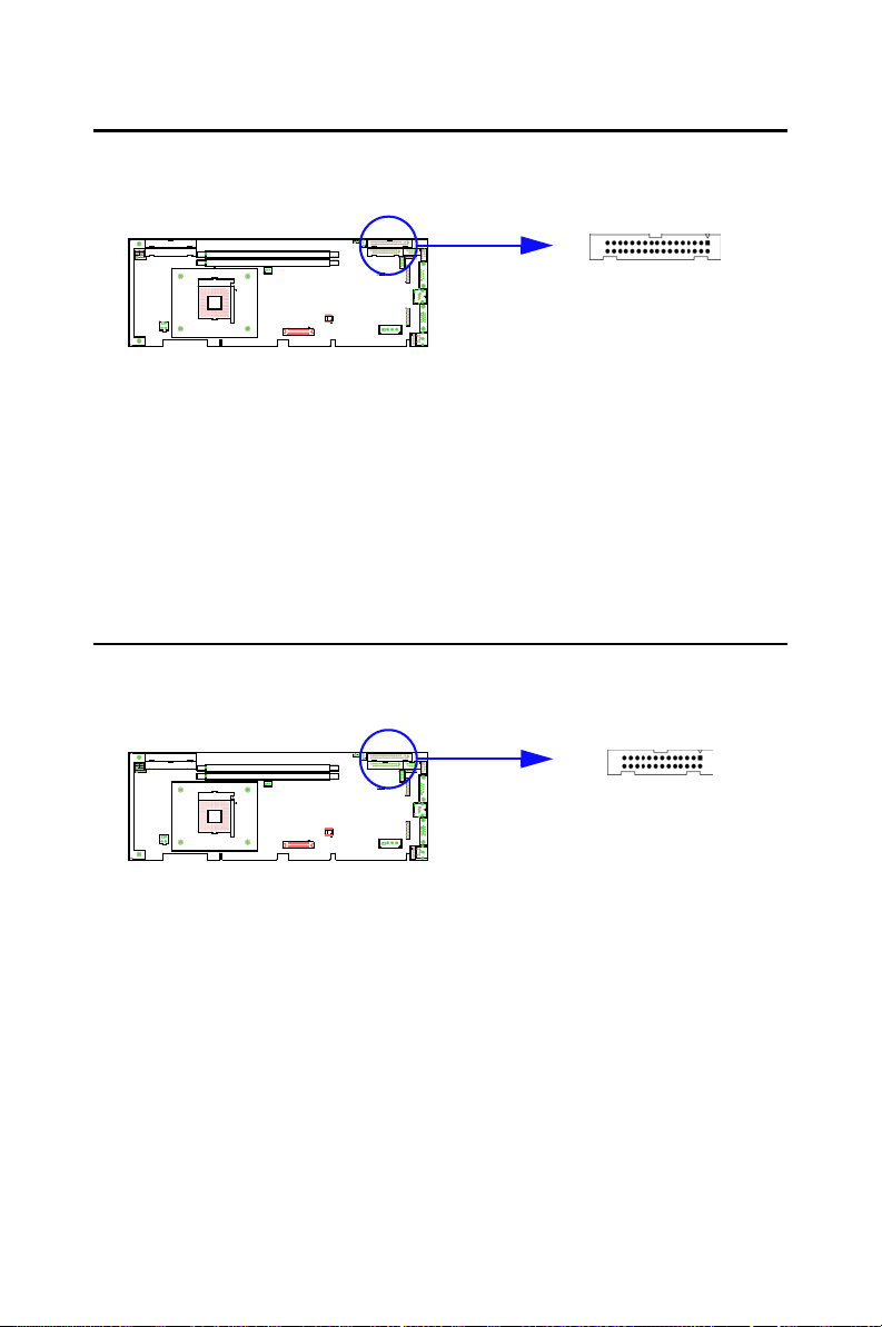
2.2 Floppy Drive Connector (CN3)
CN3
You can attach up to two floppy disk drives to the onboard connector. You
can use any combination of 5.25" (360 KB / 1.2 MB) and/or 3.5" (720 KB
/ 1.44/2.88 MB) drives. The card comes with a 34-pin daisy-chain drive
connector cable. On one end of the cable is a 34-pin flat-cable connector.
On the other end are two floppy disk drive connectors. The one on the end
(after the twist in the cable) connects to the A: floppy drive. The one in
the middle connects to the B: floppy drive.
2.3 Parallel Port (CN4)
CN4
The parallel port is normally used to connect the CPU card to a printer.
The onboard parallel port can be accessed through a 26-pin flat-cable
connector, CN4. The card comes with an adapter cable which lets you use
a traditional DB-25 connector. The cable has a 26-pin connector on one
end and a DB-25 connector on the other, mounted on a retaining bracket.
The bracket installs at the end of an empty slot in your chassis, giving you
access to the connector.
The parallel port is designated as LPT1, and can be disabled or changed to
LPT2 or LPT3 in the system BIOS setup.
To install the bracket, find an empty slot in your chassis. Unscrew the
plate that covers the end of the slot. Screw in the bracket in place of the
17
Page 32
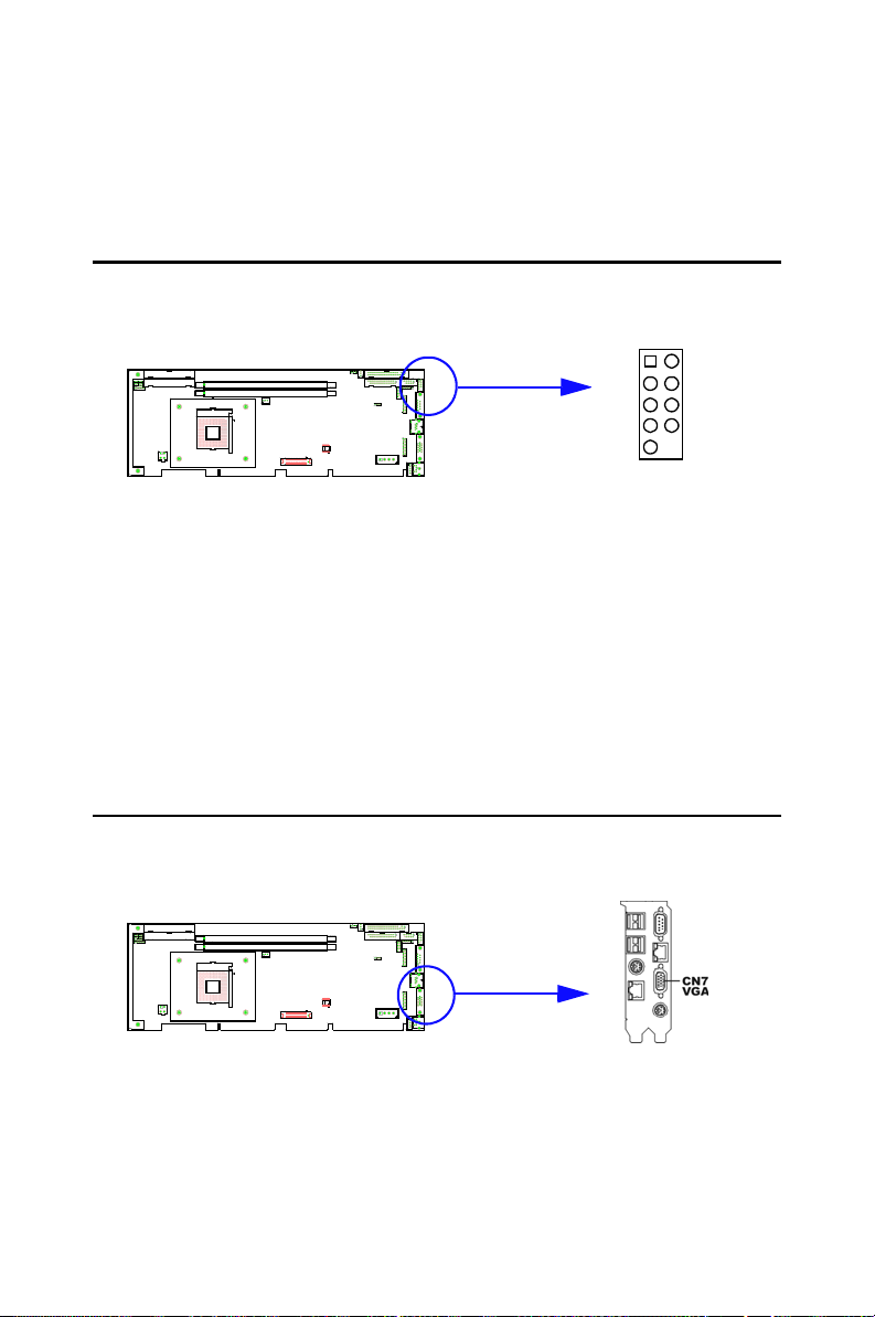
plate. Next, attach the flat-cable connector to CN4 on the CPU card. Wire
1 of the cable is red or blue, and the other wires are gray. Make sure that
wire 1 corresponds to pin 1 of CN4. Pin 1 is on the upper right side of
CN4
2.4 USB Port (CN6)
Pin 1
CN6
The PCA-6005 provides four USB (Universal Serial Bus) interfaces,
which give complete Plug & Play and hot attach/detach for up to 127
external devices.The USB interface complies with USB Specification
Rev. 1 and is fuse-protected.
The USB interface is accessed through a 10-pin flat-cable connector,
CN6. The adapter cable has a 10-pin connector on one end and two USB
connectors on the bracket.
The USB interface can be disabled in the system BIOS setup.
2.5 VGA Connector (CN7)
The PCA-6005 includes an AGP SVGA interface that can drive a standard CRT display. CN7 is a standard 15-pin D-SUB connector commonly
PCA-6005 User’s Manual 18
Page 33
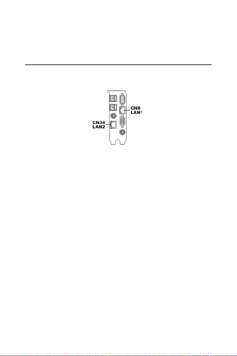
used for VGA. Pin assignments for CRT connector CN7 are detailed in
Appendix B.
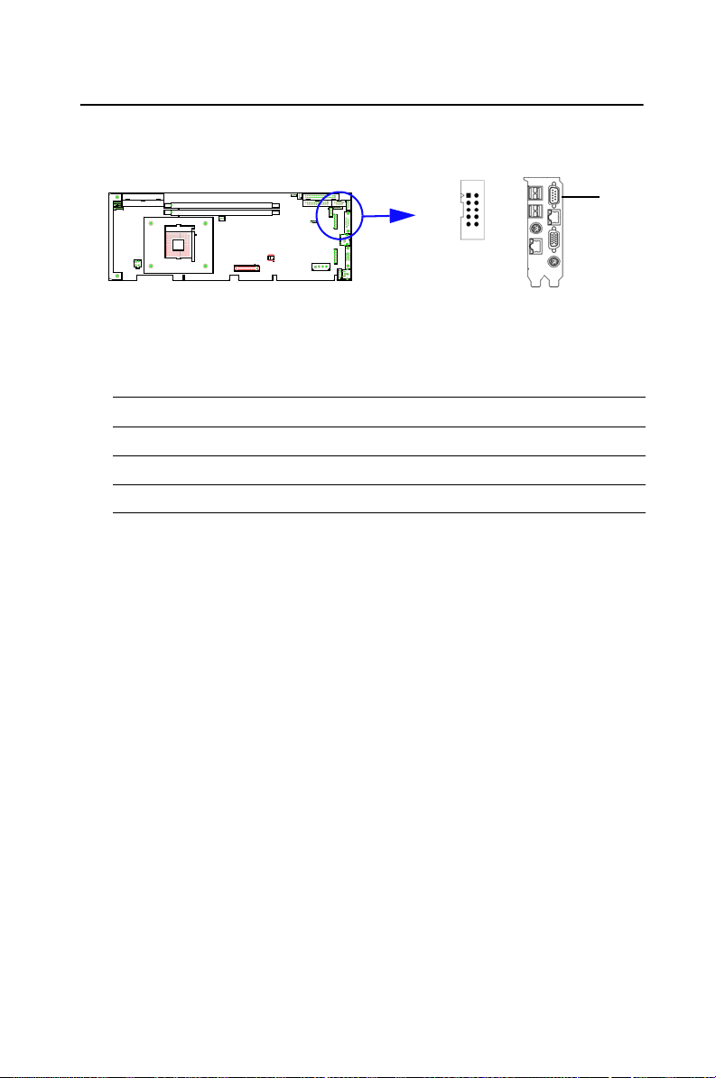
2.6 10/100Base-T Ethernet Connector (CN8 and CN34)
The PCA-6005 is equipped with dual high-performance 32-bit PCI-bus
Ethernet interface, which is fully compliant with IEEE 802.3/u 10/100
Mbps CSMA/CD standards. It is supported by all major network operating systems and is 100% Novell NE-2000 compatible. An onboard RJ-45
jack provides convenient 10/100Base-T RJ-45 operation.
19
Page 34
2.7 Serial Ports (CN9: COM1; CN10: COM2)
CN10
The PCA-6005 offers two serial ports, CN9 as COM1 and CN10 as
COM2. These ports can connect to serial devices, such as a mouse or
printers, or to a communication network
Table 2.1: Serial port connections (COM1, COM2)
Connector Ports Address Interrupt
CN9 COM1 3F8*, 3E8 IRQ4
CN10 COM2 2F8*, 2E8 IRQ3
* default settings
The IRQ and address ranges for both ports are fixed. However, if you
want to disable the port or change these parameters later, you can do this
in the system BIOS setup.
Different devices implement the RS-232 standard in different ways. If
you are having problems with a serial device, be sure to check the pin
assignments for the connector.
CN9
PCA-6005 User’s Manual 20
Page 35
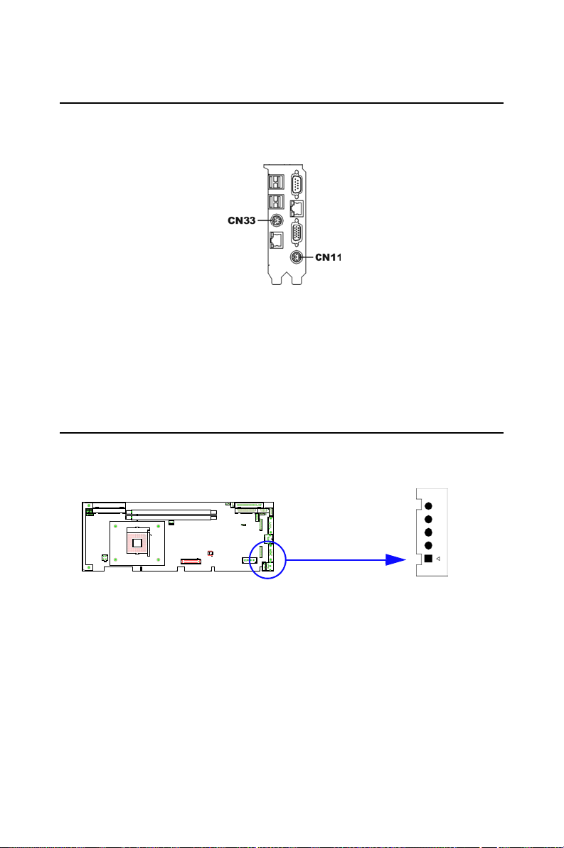
2.8 PS/2 Keyboard and Mouse Connector (CN11 and CN33)
Two 6-pin mini-DIN connectors (CN11 and CN33) on the card mounting
bracket provide connection to a PS/2 keyboard and a PS/2 mouse, respectively. CN11 can also be connected to an adapter cable (P/N:
1700060202, available from Advantech) for connecting to both a PS/2
keyboard and a PS/2 mouse.
2.9 External Keyboard Connector (CN12)
CN12
In addition to the PS/2 mouse/keyboard connector on the PCA-6005's
rear plate, there is also an extra onboard external keyboard connector.
This gives system integrators greater flexibility in designing their systems.
21
Page 36
2.10 CPU Fan Connector (CN14)
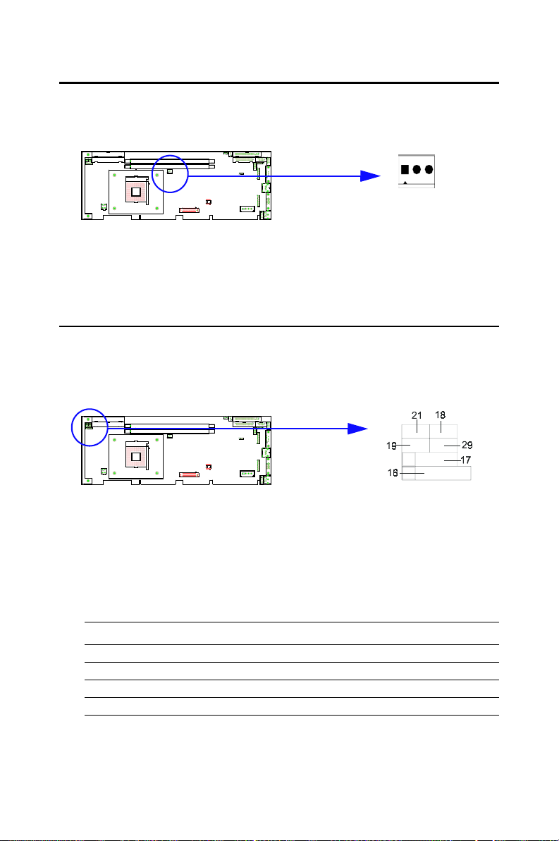
CN14
This connector supports a cooling fan with tachometer output.
2.11 Front Panel Connectors (CN16, CN17, CN18, CN19, CN21 and CN29)
There are several external switches to monitor and control the PCA-6005.
2.11.1 Keyboard lock and power LED (CN16)
CN16 is a 5-pin connector for the power on LED. Refer to Appendix B
for detailed information on the pin assignments. If a PS/2 or ATX power
supply is used, the system's power LED status will be as indicated below:
Table 2.2: PS/2 or ATX power supply LED status
Power mode LED (PS/2 power) LED (ATX power)
System On On On
System Suspend Fast flashes Fast flashes
System Off Off Slow flashes
PCA-6005 User’s Manual 22
Page 37
2.11.2 External speaker (CN17)
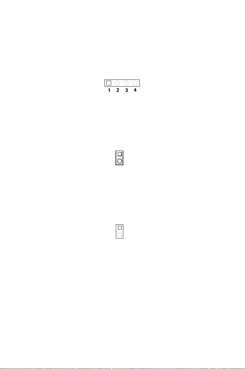
CN17 is a 4-pin connector for an extenal speaker. If there is no external
speaker, the PCA-6005 provides an onboard buzzer as an alternative. To
enable the buzzer, set pins 3-4 as closed.
2.11.3 Reset (CN18)
Many computer cases offer the convenience of a reset button. Connect the
wire from the reset button.
1
2.11.4 HDD LED (CN19)
You can connect an LED to connector CN19 to indicate when the HDD is
active.
1
2.11.5 SM Bus Connector (CN29)
This connector is reserved for Advantech's SNMP-1000 HTTP/SNMP
Remote System Manager. The SNMP-1000 allows users to monitor the
internal voltages, temperature and fans from a remote computer through
an Ethernet network.
23
Page 38
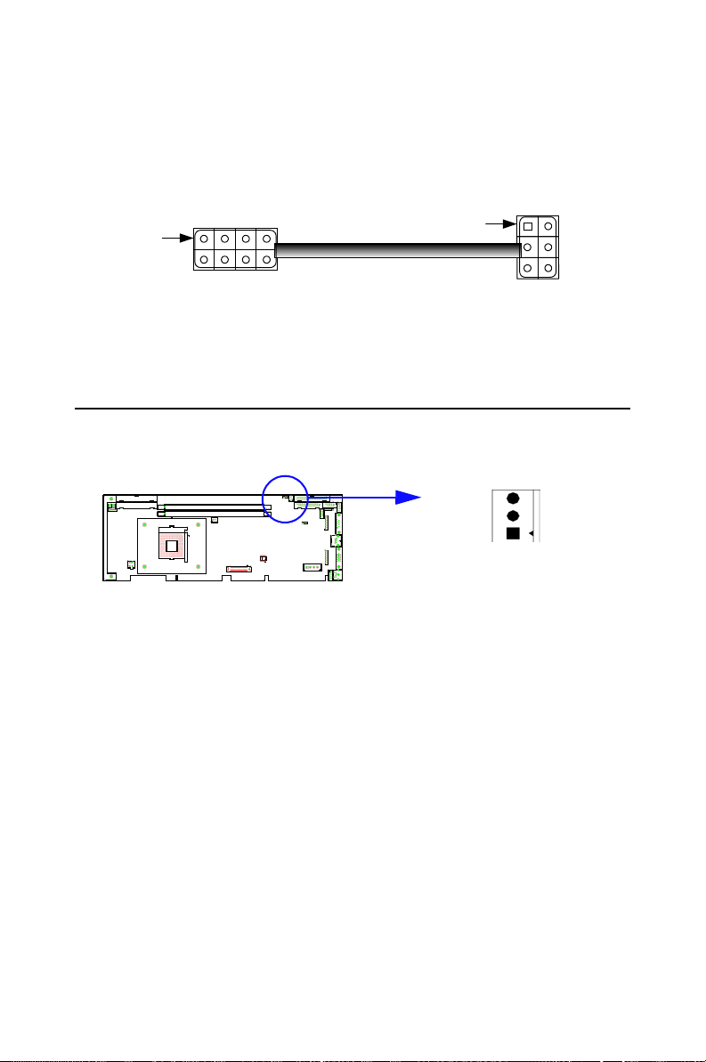
2.11.6 Connecting to SNMP-1000 remote manager
Use the 6-pin to 8-pin cable to connect the CPU card to SNMP-1000.
This cable comes with the SNMP-1000.
CN19
SNMP-1000
PIN 1
CN21 CN18
CN19 CN29
CPU Card
PIN 1
2.12 ATX Power Control Connectors (CN20 and CN21)
CN20
2.12.1 ATX feature connector (CN20) and soft power
switch connector (CN21)
The PCA-6005 can support an advanced soft power switch function if an
ATX power supply is used. To enable the soft power switch function:
1. Take the specially designed ATX-to-PS/2 power cable out of the
accessory bag.
2. Connect the 3-pin plug of the cable to CN20 (ATX feature connector).
3. Connect the power on/off button to CN21. (A momentary type of
button should be used.)
Note: If you will not be using an ATX power connector,
make sure that pins 2-3 of CN20 are closed.
PCA-6005 User’s Manual 24
Page 39

Warnings: 1. Make sure that you unplug your power sup-
ply when adding or removing expansion cards
or other system components. Failure to do so
may cause severe damage to both your CPU
card and expansion cards.
2. ATX power supplies may power on if certain
motherboard components or connections are
touched by metallic objects.
Important:
Make sure that the ATX power supply can take
at least a 720 mA load on the 5 V standby lead
(5VSB). If not, you may have difficulty powering
on your system and/or supporting the "Wakeon-LAN" function.
2.12.2 Controlling the soft power switch
Users can also identify the current power mode through the system's
power LED (see Section 2.13.1).
2.13 Auxiliary power input (CN46 & ATX1)
To supply adequate 12V power to the CPU card, the PCA-6005 provides
two auxiliary power connectors, CN46 and ATX1. CN46 accepts a standard device power connector, and ATX1 accepts 4-pin ATX 12V connector.
Warning: Either CN31 or ATX1 has to be connected, oth-
erwise the system may be unstable.
25
Page 40

PCA-6005 User’s Manual 26
Page 41

Award BIOS Setup
This chapter describes how to set thecard’s BIOS configuration data.
CHAPTER
3
27
Page 42
Chapter 3 Award BIOS Setup
3.1 Introduction
Award’s BIOS ROM has a built-in setup program that allows users to
modify the basic system configuration. This type of information is stored
in battery-backed memory (CMOS RAM) so that it retains the setup
information when the power is turned off.
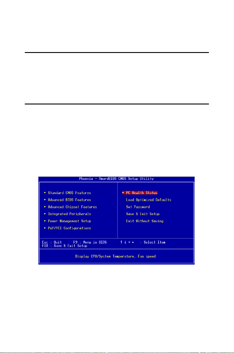
3.2 Entering Setup
Turn on the computer and check for the “patch code”. If there is a number
assigned to the patch code, it means that the BIOS supports your CPU. If
there is no number assigned to the patch code, please contact Advantech’s
applications engineer to obtain an up-to-date patch code file. This will
ensure that your CPU’s system status is valid. After ensuring that you
have a number assigned to the patch code, press <Del> to allow you to
enter the setup.
Figure 3.1: Award BIOS Setup initial screen
PCA-6005 User’s Manual 28
Page 43
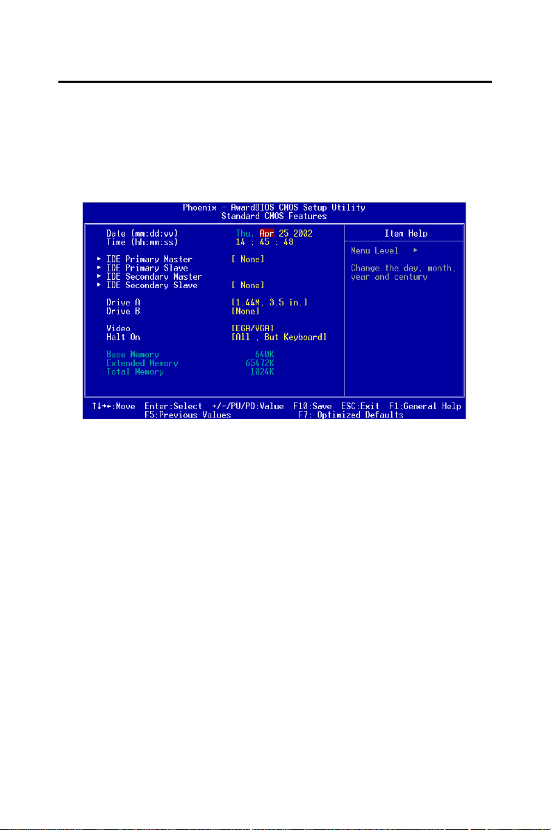
3.3 Standard CMOS Setup
Choose the “Standard CMOS Features” option from the “Initial Setup
Screen” menu, and the screen below will be displayed. This menu allows
users to configure system components such as date, time, hard disk drive,
floppy drive, display, and memory.
3.3.1 CMOS RAM backup
The CMOS RAM is powered by an onboard button cell battery. When
BIOS CMOS Setup has been completed, CMOS RAM data is automatically backed up to Flash ROM. If conditions in a harsh industrial enviroment cause a soft error, BIOS will recheck the data and automatically
restore the original data for booting.
Note: If you intend to update CMOS RAM data, you
have to click on “DEL” within two seconds of the
“CMOS checksum error....” display screen mes-
sage appearing. Then enter the “Setup” screen
to modify the data. If the “CMOS checksum
error....” message appears again and again,
please check to see if you need to replace the
battery in your system.
29
Page 44
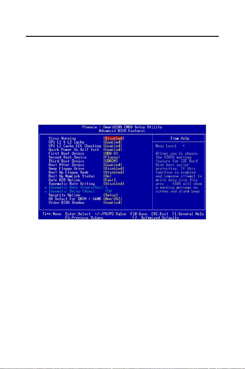
3.4 Advanced BIOS Features
The “Advanced BIOS Features” screen appears when choosing the
“Advanced BIOS Features” item from the “Initial Setup Screen” menu. It
allows the user to configure the CPU card according to his particular
requirements.
Below are some major items that are provided in the Advanced BIOS
Features screen.
A quick booting function is provided for your convenience. Simply
enable the Quick Booting item to save yourself valuable time.
Figure 3.2: Advanced BIOS features screen
3.4.1 Virus Warning
If enabled, a warning message and alarm beep activates if someone
attempts to write here. The commands are “Enabled” or “Disabled.”
3.4.2 CPU L1 & L2 Cache
Enabling this feature speeds up memory access. The commands are
“Enabled” or “Disabled.”
3.4.3 CPU L2 Cache ECC Checking
Enabling allows CPU L2 cache checking. The commands are “Enabled”
or “Disabled.”
PCA-6005 User’s Manual 30
Page 45

3.4.4 First/Second/Third/Other Boot Device
The BIOS tries to load the OS with the devices in the sequence selected.
Choices are: Floppy, LS/ZIP, HDD, SCSI, CDROM, LAN, Disabled.
3.4.5 Swap Floppy Drive
Logical name assignments of floppy drives can be swapped if there is
more than one floppy drive. The commands are “Enabled” or “Disabled.”
3.4.6 Boot UP Floppy Seek
Selection of the command “Disabled” will speed the boot up. Selection of
“Enabled” searches disk drives during boot up.
3.4.7 Boot Up NumLock Status
This feature selects the “power on” state for NumLock. The commands
are “Enabled” or “Disabled.”
3.4.8 Gate A20 Option
Normal The A20 signal is controlled by the keyboard controller. Fast
(Default) The A20 signal is controlled by the chipset.
3.4.9 Typematic Rate Setting
The typematic rate is the rate key strokes repeat as determined by the keyboard controller. The commands are “Enabled” or “Disabled.” Enabling
allows the typematic rate and delay to be selected.
3.4.10 Typematic Rate (Chars/Sec)
BIOS accepts the following input values (characters/second) for typematic rate: 6, 8, 10, 12, 15, 20, 24, 30.
3.4.11 Typematic Delay (msec)
Typematic delay is the time interval between the appearance of two consecutive characters, when holding down a key. The input values for this
category are: 250, 500, 750, 1000 (msec).
3.4.12 Security Option
This setting determines whether the system will boot up if the password is
denied. Access to Setup is, however, always limited. System The system
will not boot, and access to Setup will be denied if the correct password is
31
Page 46

not entered at the prompt. Setup The system will boot, but access to Setup
will be denied if the correct password is not entered at the prompt.
Note: To disable security, select “PASSWORD SET-
TING” in the main menu. At this point, you will
be asked to enter a password. Simply press
<Enter> to disable security. When security is
disabled, the system will boot, and you can
enter Setup freely.
3.4.13 OS Select for DRAM > 64MB
This setting allows selecting an OS with greater than 64MB of RAM.
Commands are “Non-OS2” or “OS2.”
3.4.14 Video BIOS Shadow
Enable copies video BIOS to sharow RAM for performnace improving.
Choices are Enable, Disable.
PCA-6005 User’s Manual 32
Page 47
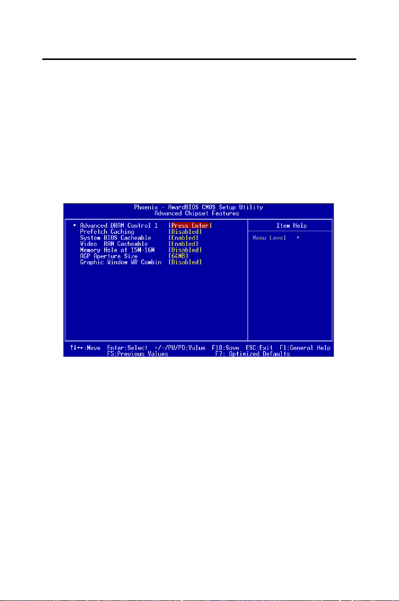
3.5 Advanced Chipset Features
By choosing the “Advanced Chipset Features ”option from the “Initial
Setup Screen” menu, the screen below will be displayed. This sample
screen contains the manufacturer’s default values for this CPU card, as
shown in Figure 3-5: .
Note: DRAM default timings have been carefully cho-
sen and should ONLY be changed if data is
being lost. Please first contact technical support
Figure 3.3: Advanced chipset features screen
33
Page 48
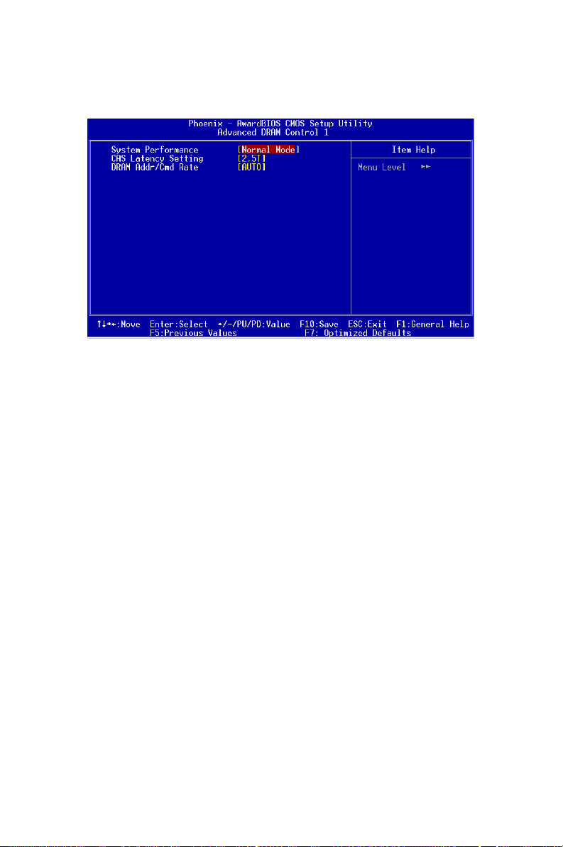
3.5.1 Advanced DRAM control 1
This item allows you to control the DRAM speed.
3.5.1.1 System performance
This item should be set at "Normal Mode" to ensure system stabil-
ity.
3.5.1.2 CAS Latency Setting
This item is used to adjust the CAS latency. Default setting is 2.5T.
3.5.1.3 DRAM Addr/Cmd Rate
This item is set at "AUTO". It is not recommended to change the
setting.
3.5.2 Prefetch Caching
This item allows to enable/disable the PCI bus prefectch caching. Default
is disabled.
3.5.3 System BIOS Cacheable
Selecting Enabled allows caching of the system BIOS ROM at F0000hFFFFFh, resulting in better system performance. However, if any program writes to this memory area, a system error may result. The choice:
Enabled, Disabled.
PCA-6005 User’s Manual 34
Page 49
3.5.4 Memory Hole
In order to improve performance, certain space in memory is reserved for
ISA cards. This memory must be mapped into the memory space below
16MB. The Choice: 15M-16M, Disabled.
3.5.5 AGP Aperture Size
Select the size of Accelerated Graphics Port (AGP) aperture. The aperture
is a portion of the PCI memory address range dedicated for graphics
memory address space. Host cycles that hit the aperture range are forwarded to the AGP without any translation. The Choice: 4M, 8M, 16M,
32M, 65M, 128M, 256M.
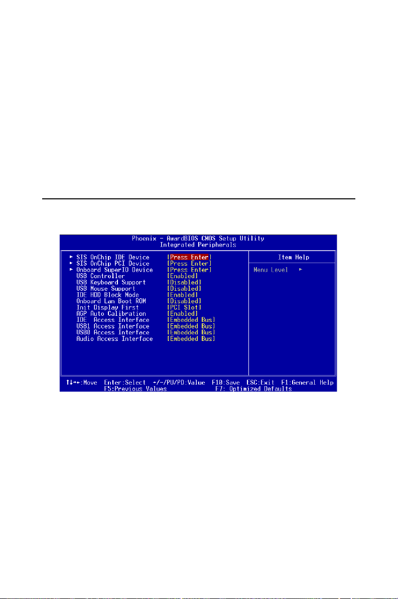
3.6 Integrated Peripherals
Figure 3.4: Integrated peripherals
35
Page 50
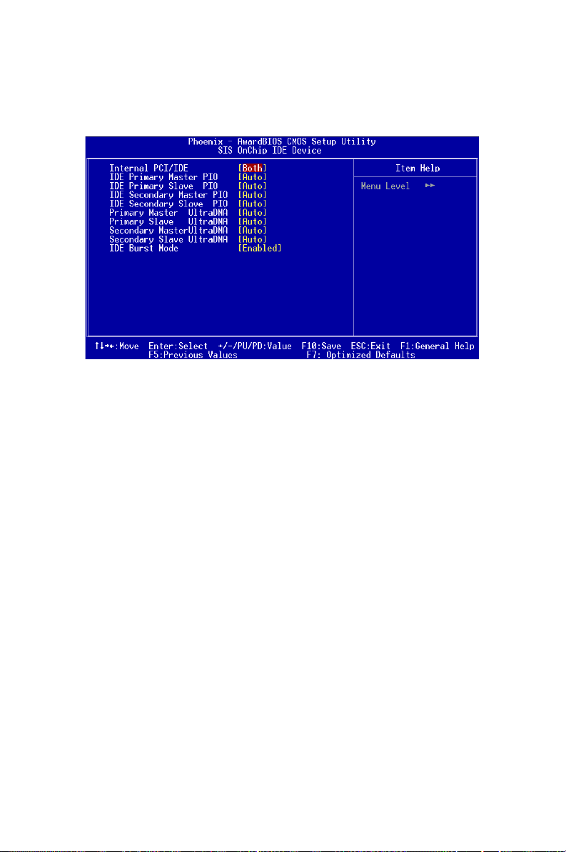
3.6.1 SiS OnChip IDE Device
Press Enter to set the internal IDE controller.
3.6.1.1. IDE Primary Master/Slave PIO/UDMA Mode, IDE
Secondary Master/Slave PIO/UDMA Mode (Auto) Each channel
(Primary and Secondary) has both a master and a slave, making
four IDE devices possible. Because each IDE device may have a different Mode timing (0, 1, 2, 3, 4), it is necessary for these to be independent.
The default setting “Auto” will allow autodetection to ensure optimal performance.
PCA-6005 User’s Manual 36
Page 51
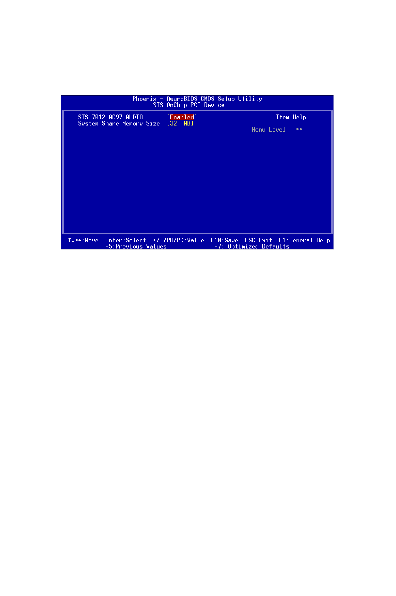
3.6.2 SiS OnChip PCI Device
Press Enter to set the on-chip PCI devices.
3.6.2.1 SiS-7012 AC-97 Audio
If the AC-97 audio function is required, set this item to Enabled.
3.6.2.2 System Share Memory Size
This item is used to set the shared size of system memory for VGA
display. The choices are: 4 MB, 8 MB, 16 MB, 32 MB and 64 MB.
37
Page 52
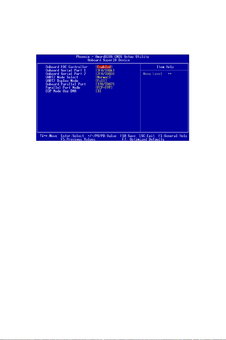
3.6.3 Onboard Super IO Device
Press enter to set up the on board super I/O device.
3.6.3.1 Onboard FDC Controller
When enabled, this field allows you to connect your floppy disk
drives to the onboard floppy disk drive connector instead of a separate
controller card. If you want to use a different controller card to connect
the floppy disk drives, set this field to Disabled.
3.6.3.2. Onboard Serial Port 1 (3F8H/IRQ4)
The settings are Auto 3F8/IRQ4, 2F8/IRQ3, 3E8/IRQ4, 2E8/IRQ3,
and Disabled for the on-board serial connector.
3.6.3.3. Onboard Serial Port 2 (2F8H/IRQ3)
The settings are Auto 3F8/IRQ4, 2F8/IRQ3, 3E8/IRQ4, 2E8/IRQ3,
and Disabled for the on-board serial connector.
3.6.3.4. UART 2 Mode Select
This item allows you to select UART mode.
3.6.3.5. Onboard Parallel Port (378H/IRQ7)
This field sets the address of the on-board parallel port connector
You can select either 3BC/IRQ7, 378/IRQ7, 278/IRQ5 or Disabled. If
you install an I/O card with a parallel port, make sure there is no conflict
in the address assignments. The CPU card can support up to three parallel
ports, as long as there are no conflicts for each port.
PCA-6005 User’s Manual 38
Page 53

3.6.3.6 Onboard Parallel Port Mode (ECP + EPP)
This field allows you to set the operation mode of the parallel port.
The setting “Normal” allows normal speed operation, but in one direction
only. “EPP” allows bidirectional parallel port operation at maximum
speed. “ECP” allows the parallel port to operate in bidirectional mode and
at a speed faster than the maximum data transfer rate. “ECP + EPP”
allows normal speed operation in a two-way mode.
3.6.3.7. ECP Mode Use DMA
This selection is available only if you select “ECP” or “ECP +
EPP” in the Parallel Port Mode field. In ECP Mode Use DMA, you can
select DMA channel 1, DMA channel 3, or Disable. Leave this field on
the default setting.
3.6.4 USB controller
This should be enabled if your system has a USB installed on the system
board and you want to use it. Even when so equipped, if you add a higher
performance controller, you will need to disable this feature. The choice:
Enabled, Disabled.
3.6.5 USB Keyboard Support
Select Enabled if your system contains a Universal Serial Bus (USB) controller and you have a USB keyboard. The choice: Enabled, Disabled.
3.6.6 USB Mouse Support
Select Enabled if your system contains a Universal Serial Bus (USB)controller and you have a USB mouse. The choice: Enabled, Disabled.
3.6.7 IDE HDD Block Mode
Block mode is also called block transfer, multiple commands, or multiple
sector read/write. If your IDE hard drive supports block mode (most new
drives do), select Enabled for automatic detection of the optimal number
of block read/writes per sector the drive can support. The choice:
Enabled, Disabled
3.6.8 Onboard Lan Boot Rom
The LAN boot ROM for boot on LAN function can be enabled or disabled.
3.6.9 Init Display First
This item allows you to choose which one to activate first, PCI Slot or
AGP. The choices: PCI Slot, AGP.
39
Page 54
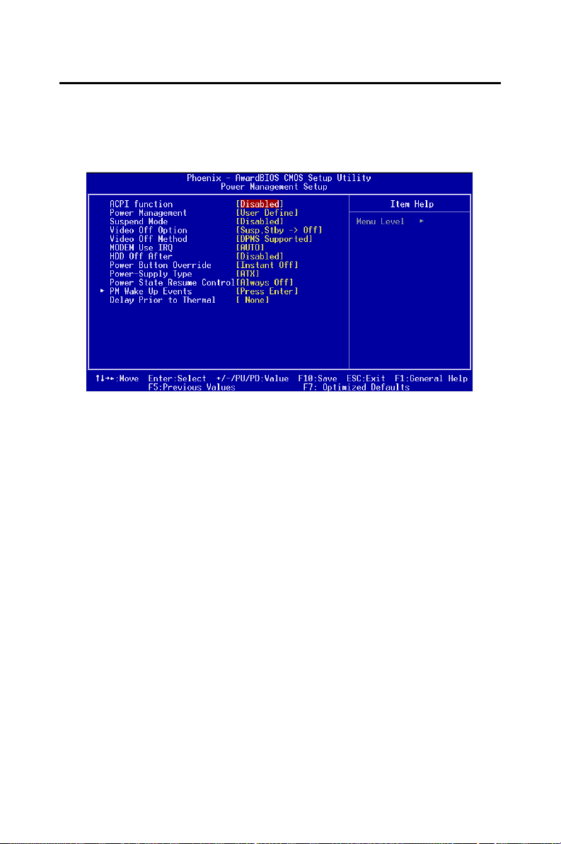
3.7 Power Management Setup
The power management setup controls the CPU card’s “green” features to
save power. The following screen shows the manufacturer’s defaults:
Figure 3.5: Power management setup screen
3.7.1 ACPI function
This item allows you to enable/disable the Advanced Configuration and
Power Management (ACPI). The choice: Enabled, Disabled.
3.7.2 Power Management
This category allows you to select the type (or degree) of power saving
and is directly related to the following modes:
1. HDD Power Down
2. Doze Mode
3. Suspend Mode
PCA-6005 User’s Manual 40
Page 55

There are four selections for Power Management, three of which have
fixed mode settings.
Disable (Default) No power management. Disables all four modes.
Min. Power Saving Minimum power management. Doze Mode=1 hr. Standby Mode=1 hr.,
Max Power Saving Maximum power management. Doze Mode=1 min., Standby Mode=1
User Defined Allows you to set each mode individually. When not disabled, each of the
Suspend Mode=1 hr., and HDD Power Down=15 min.
min., Suspend Mode=1 min., and HDD Power Down=1 min.
ranges are from 1 min. to 1 hr. except for HDD Power Down which
ranges from 1 min. to 15 min. and disable.
3.7.3 Video Off Option
When enabled, this feature allows the VGA adapter to operate in a power
saving mode.
Always On Monitor will remain on during power saving modes.
Suspend N--->Off Monitor blanked when the systems enters the Suspend mode.
Susp, Stby--->Off Monitor blanked when the system enters either Suspend or Standby
modes.
All Modes Ñ>Off Monitor blanked when the system enters any power saving mode.
3.7.4 Video Off Method
This determines the manner in which the monitor is blanked.
V/H SYNC+Blank This selection will cause the system to turn off the vertical and horizontal
Blank Screen This option only writes blanks to the video buffer
DPMS Select this option if your monitor supports the Display Power Management
synchronization ports and write blanks to the video buffer.
Signaling (DPMS) standard of the Video Electronics Standards to select
video power management values.
3.7.5 MODEM Use IRQ
This determines the IRQ in which the MODEM can use.The choices: 3, 4,
5, 7, 9, 10, 11, NA.
3.7.6 Soft-Off by PWRBTN
If you choose “Instant-Off”, then pushing the ATX soft power switch button once will switch the system to “system off” power mode. You can
choose “Delay 4 sec.” If you do so, then pushing the button for more than
4 seconds will turn off the system, whereas pushing the button momentarily (for less than 4 seconds) will switch the system to “suspend” mode.
3.7.7 Power-Supply Type
C h oic e: AT, AT X
41
Page 56
3.7.8 Power State Resume Control
This field lets you to determine the state that your computer returns after
a power failure. If sets to Off, the PC will not boot after a power failure. If
sets to On, the PC will restart after a power failure. If sets to Auto, the PC
will go back to the previous state before a power failure occurred. For
instance, if the PC is power-on when power system fails, the PC will
restart when power system is working again. If the PC is power-ff when
power system fails, the PC will not boot when power system is working
again. The Choice: Off, On, Auto.
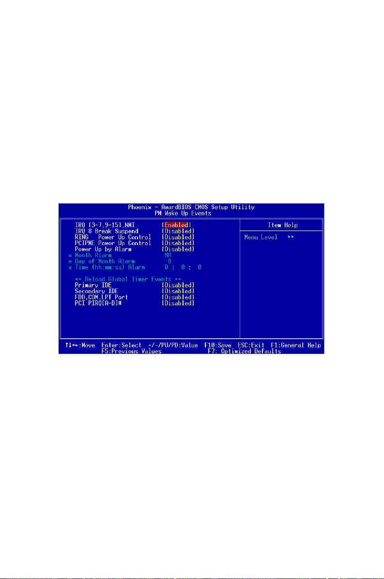
3.7.9 PM Wake Up Events
Users can enable some system events to wake up the system.
Figure 3.6: Wake Up Events
PCA-6005 User’s Manual 42
Page 57
3.8 PnP/PCI Configurations
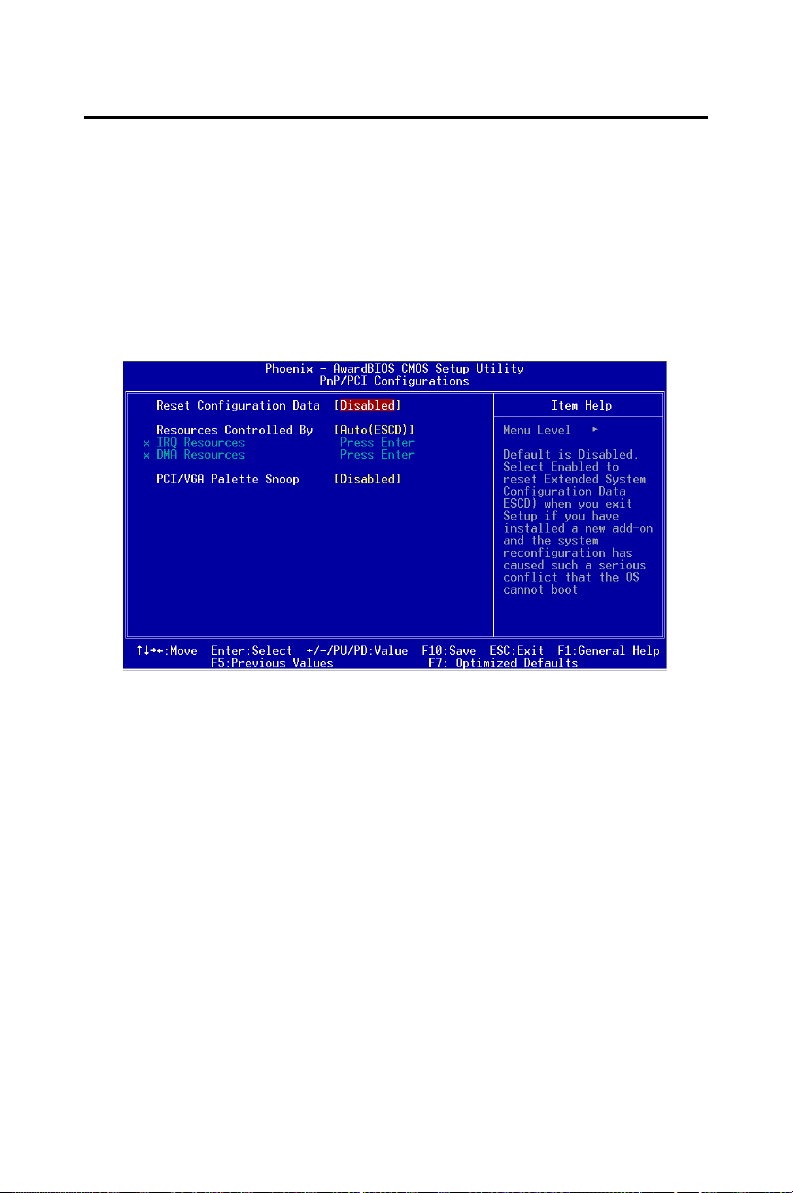
3.8.1 Reset Configuration Data.
Note: This is left “Disabled.” Select “Enabled” to reset
Extended System Configuration Data (ECSD) if
you have installed a new add-on and your OS
won’t boot and you need to reconfigure
Figure 3.7: PnP/PCI configurations screen
43
Page 58
3.9 PC Health Status
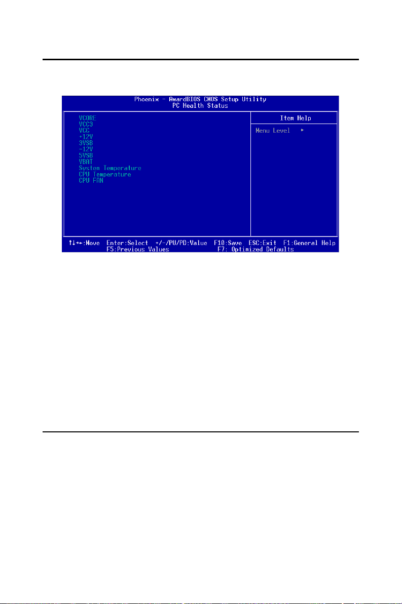
Figure 3.8: PC health status screen
3.9.1 Current CPU Temperature
This shows you the current CPU1 temperature.
3.9.2 Current CPUFAN Speed
This shows you the current CPUFAN speed.
3.9.3 VCORE
This shows CPU1 core voltage. 3.10.4 +2.5/ +3.3V/ + 5V/ +12V. This
shows you the voltage of +2.5/ +3.3V/ + 5V/ +12V
3.10 Load Optomized Defaults
“LOAD SETUP DEFAULTS” loads the values required by the system for
maximum performance.
PCA-6005 User’s Manual 44
Page 59

3.11 Set Password
To change the password:
1. Choose the “Set Password” option from the “Initial Setup Screen”
menu and press <Enter>. The screen will display the following
message:
Enter Password:
Press <Enter>.
2. If the CMOS is good or if this option has been used to change the
default password, the user is asked for the password stored in the
CMOS. The screen will display the following message:
Confirm Password:
Enter the current password and press <Enter>.
3. After pressing <Enter> (ROM password) or the current password
(user-defined), you can change the password stored in the CMOS.
The password must be no longer than eight (8) characters. Remember, to enable the password setting feature, you must first select
either “Setup” or “System” from the “Advanced BIOS Features”
menu.
3.12 Save & Exit Setup
If you select this and press <Enter>, the values entered in the setup utilities will be recorded in the CMOS memory of the chipset. The microprocessor will check this every time you turn your system on and compare
this to what it finds as it checks the system. This record is required for the
system to operate.
3.13 Exit Without Saving
Selecting this option and pressing <Enter> lets you exit the setup program
without recording any new values or changing old ones.
45
Page 60

PCA-6005 User’s Manual 46
Page 61

AGP SVGA Setup
The PCA-6005 features an integrated
high performance VGA interface. This
chapter provides instructions for
installing and operating the software
drivers on the display driver CD
included in your package.
CHAPTER
4
47 Chapter 4
Page 62

Chapter 4 AGP SVGA Setup
4.1 Before You Begin
To facilitate the installation of the enhanced display device drivers and
utility software, you should read the instructions in this chapter carefully
before you attempt installation. The enhanced display drivers for the
PCA-6005 board are located on the software installation CD. You must
install the drivers and utility software by using the supplied SETUP program for DOS drivers.
Note: The files on the software installation CD are
compressed. Do not attempt to install the drivers by copying the files manually. You must use
the supplied SETUP program to install the drivers.
Before you begin, it is important to note that most display drivers need to
have the relevant software application already installed in the system
prior to installing the enhanced display drivers. In addition, many of the
installation procedures assume that you are familiar with both the relevant software applications and operating system commands. Review the
relevant operating system commands and the pertinent sections of your
application software’s user’s manual before performing the installation.
4.2 Features
• Chipset integrated 2D/3D graphics accelerator
• 2 pixel rendering pipelines and 4 texture 3D graphic engine
• Ultra-AGPII. technology delivering AGP8X equalent 2GB/s bandwidth
• Advanced HW acceleration for DVD playback
• Shared memory size up to 64MB
• Integrated 333 MHz RAMDAC supports resolution up to 2048x1536
16M colors
PCA-6005 User’s Manual 48
Page 63
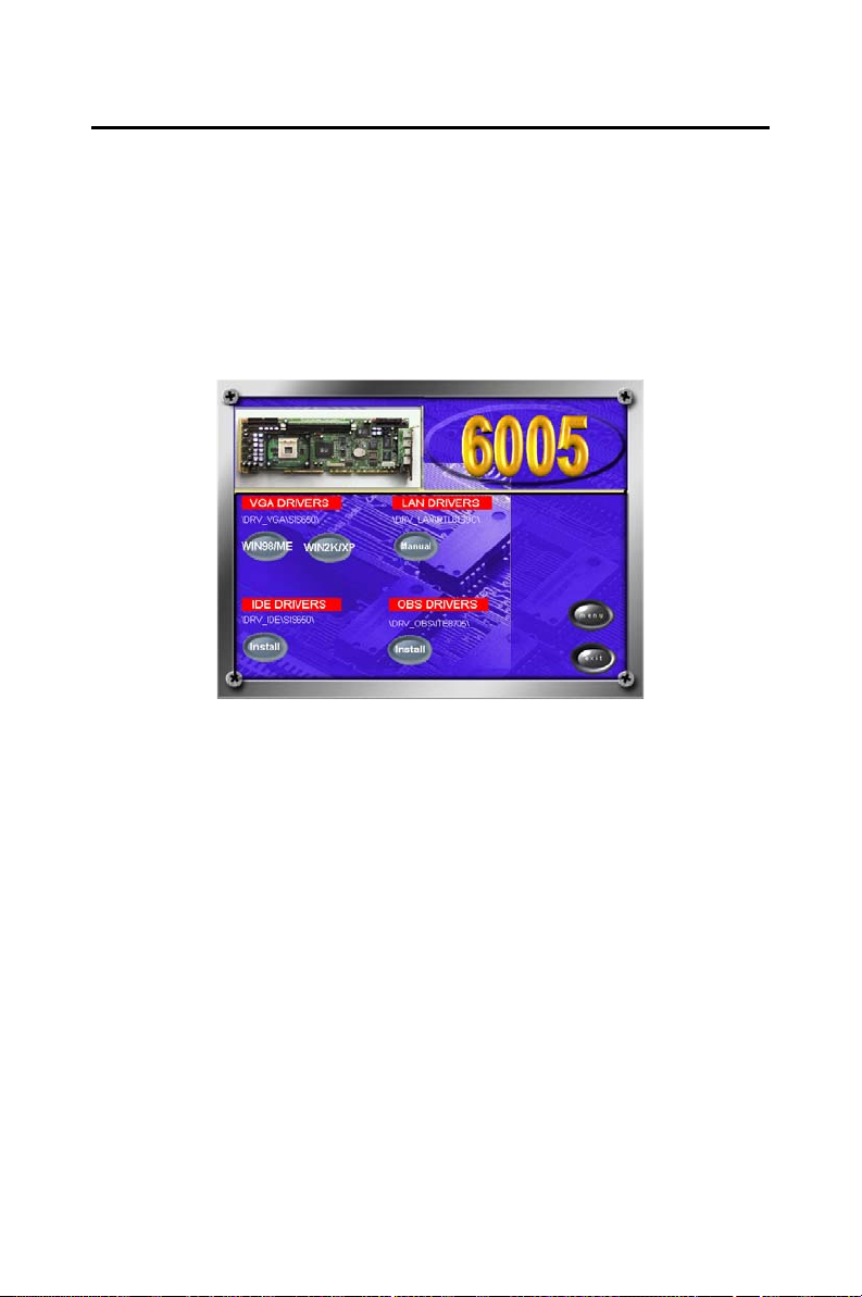
4.3 VGA Installation
First, insert CD drive. Then follow the Icons for your PCA Series model
number.
Click on the right driver for the auto-installation.
The installation programm will guide you through the whole installation
process. Follow the instruction when necessary.
49 Chapter 4
Page 64

PCA-6005 User’s Manual 50
Page 65

LAN Configuration
The PCA-6005 features an onboard
LAN interface. This chapter gives
detailed information on Ethernet configuration. It shows you how to configure the card to match your application
requirements.
CHAPTER
5
51 Chapter 5
Page 66

Chapter 5 LAN Configuration
5.1 Introduction
The PCA-6005 features an optional single/dual 32-bit 10/100 Mbps
Ethernet network interface. This interface supports bus mastering architecture and auto-negotiation features. Therefore standard twisted-pair
cabling with RJ-45 connectors for both 10 Mbps and 100 Mbps connections can be used. Extensive driver support for commonly-used network
systems is also provided.
5.2 Features
• Realtek RTL8139C Ethernet LAN controller (fully integrated 10Base-
T/100Base-TX)
• Supports Wake-on-LAN remote control function
• Supports up to128 K bytes Boot ROM
• PCI Bus Master complies with PCI Rev. 2.2
• MAC & PHY (10/100 Mbps) interfaces
• Complies to IEEE 802.3X 10Base-T and IEEE 802.3u 100Base-T inter-
faces
• 3.3 V power supply with 5 V tolerant I/Os
• Single RJ-45 connector gives auto-detection of 10 Mbps or 100 Mbps
network data transfer rates and connected cable types
• Enhancements on ACPI, PCI power management
• Compliant to PC99 standard
PCA-6005 User’s Manual 52
Page 67

5.3 Driver Installation
The PCA-6005's onboard Ethernet interface supports all major network
operating systems.
The BIOS automatically detects the LAN while booting, and assigns an
IRQ level and I/O address. No jumpers or switches are required for user
configuration.
The drivers and installation instructions are located in the following
directories of the utility CD:
• Dos: Drivers for DOS platforms
• Info: Installation instructions
• Nwserver: Drivers for Novell NetWare
• Wfw: Drivers for Windows 3.11 for Workgroups
Please refer to the text files in the Info directory for detailed information
about installing the drivers.
Note: Operating system vendors may post driver
updates on their websites. Please visit the websites of OS vendors to download updated drivers.
53 Chapter 5
Page 68
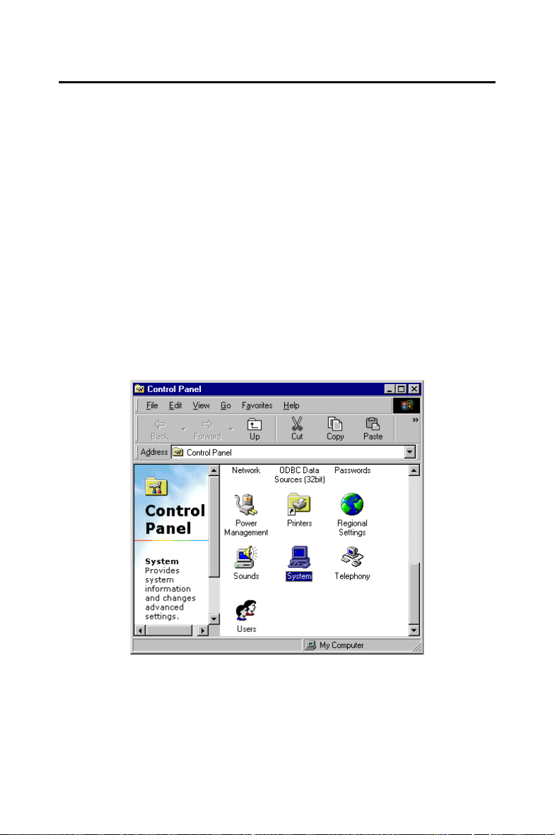
5.4 Windows 9X Drivers Setup Procedure
Note 1: If you are using Windows 98SE, your system
will find the LAN device "PCI Ethernet Controller". You must first remove this device from your
system, and then restart your computer. Then
you will be ready to install the correct driver by
following the procedure below.
Note 2: The CD-ROM drive is designated as "D"
throughout this section.
1. In the "Windows" screen, click on "Start" and select "Settings".
Then click on the "Control Panel" icon to select "System".
PCA-6005 User’s Manual 54
Page 69
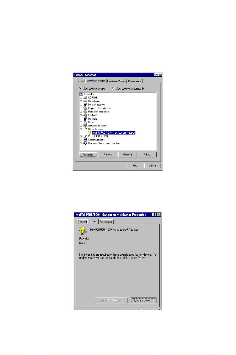
2. In the "System Properties" window, select the "Device Manager"
tab. Select "View devices by type", and navigate to: Computer\Other devices\PCI Ethernet Controller. Highlight "PCI Ethernet Controller" and click on "Properties".
3. In the "PCI Ethernet Controller Properties" window, select the
"Driver" tab. Then click on "Update Driver...".
55 Chapter 5
Page 70
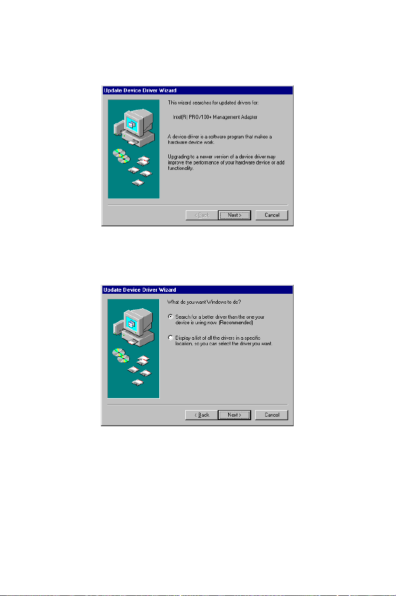
4. In the "Update Device Driver Wizard" window, click on "Next".
5. Click "Next".
PCA-6005 User’s Manual 56
Page 71
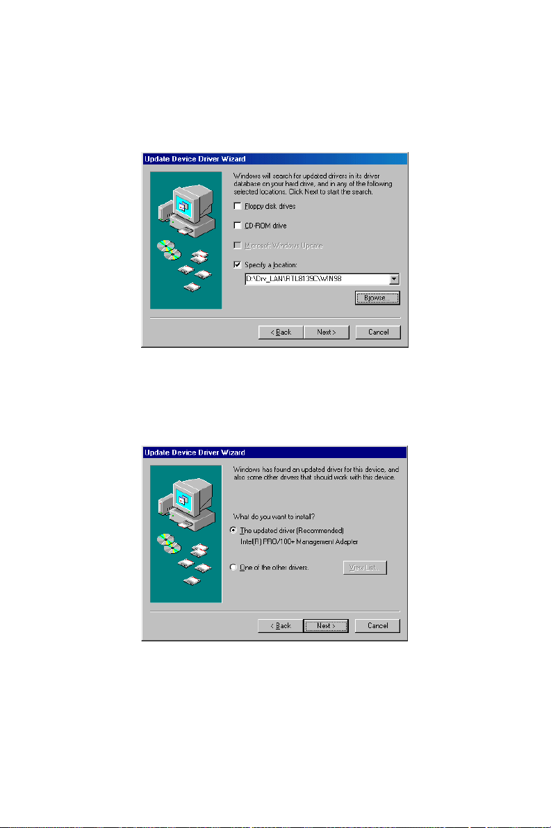
6. In the following "Update Device Driver Wizard" window,
select"Specify a location:". Type in:
"D:\Drv_LAN\RTL8139C\WIN98".Then click on "Next".
7. In the following "Update Device Driver Wizard" window, select
"The updated driver ...". Then click on "Next".
57 Chapter 5
Page 72
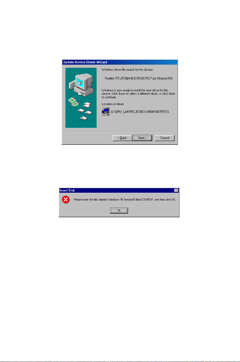
8. In the following "Update Device Driver Wizard" window, click on
"Next".
9. When the "Insert Disk" window appears, insert the utility CD into
the CD-ROM drive. Then click on "OK".
PCA-6005 User’s Manual 58
Page 73
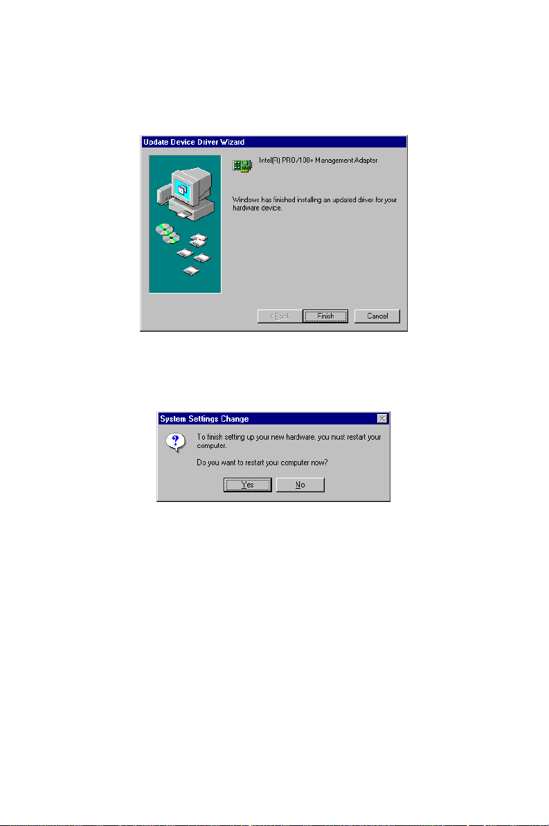
10. When the "Update Device Driver Wizard" window shows, click on
finish.
11. In the "System Settings change" window, select click on "Yes".
59 Chapter 5
Page 74
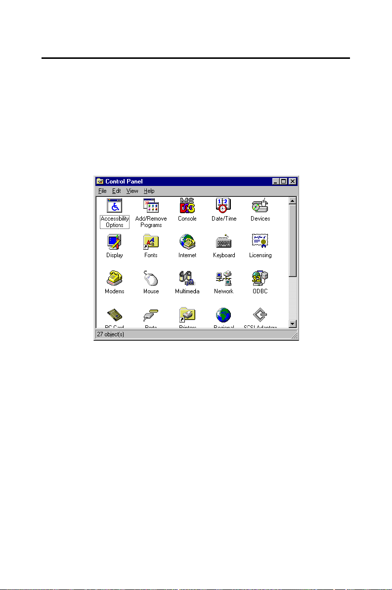
5.5 Windows NT Drivers Setup Procedure
Note: The CD-ROM drive is designated as "E"
throughout this section.
1. In the "Windows NT" screen, click on "Start" and select "Settings".
Then click on the "Control Panel" icon to select "Network".
PCA-6005 User’s Manual 60
Page 75
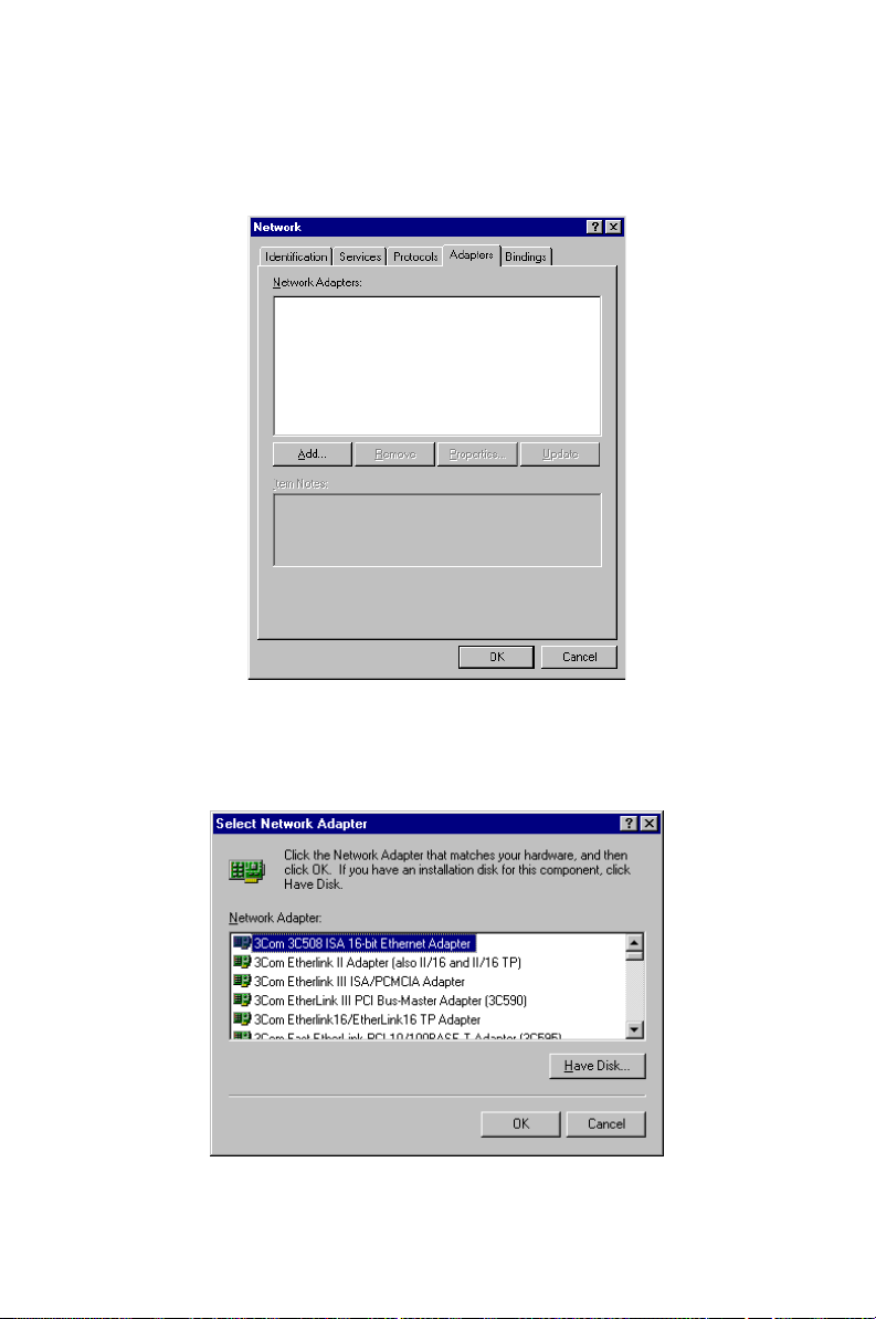
2. In the "Network" window, select the "Adapters" tab. Then click on
"Add...".
3. In the "Select Network Adapter" window, click on "Have Disk...".
61 Chapter 5
Page 76
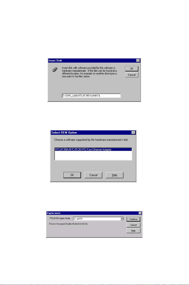
4. When the "Insert Disk" window appears, insert the utility CD into
the CD-ROM drive. The correct file path is;
D:\Drv_LAN\RTL8139C\WINNT4. When you have the correct
file path, click on "OK".
5. In the "Select OEM Option" window, click on "OK".
6. In the "Duplex mode", click "OK".
PCA-6005 User’s Manual 62
Page 77
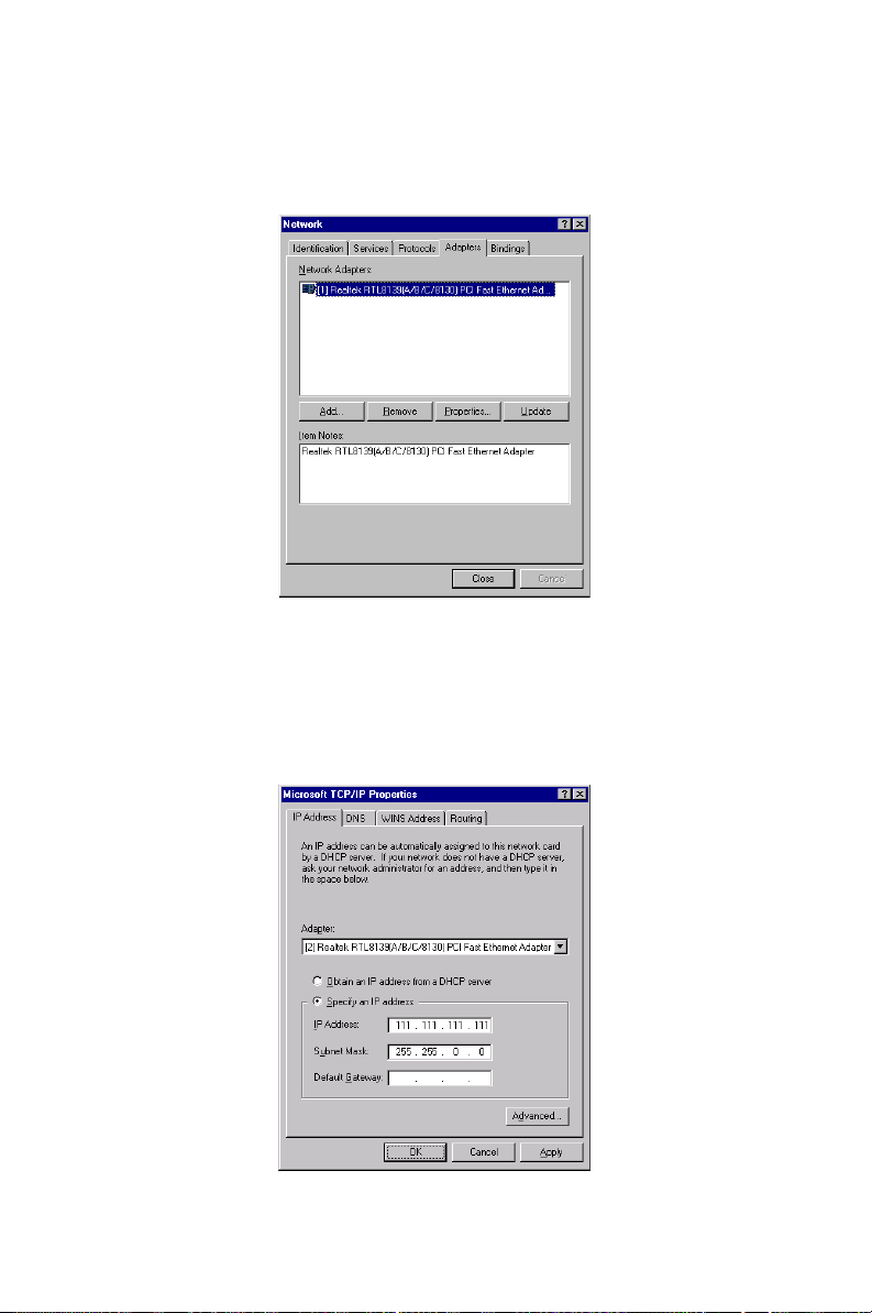
7. In the "Network" window, select the "Adapters" tab. Under "Network Adapters:", highlight "Realtek RTL8139CA/B/C(8130).
8. In the "Microsoft TCP/IP Properties" window, select the "IP
Address" tab. Then select "Specify an IP address". Type in the IP
Address and Subnet Mask details. Then click on "OK".
63 Chapter 5
Page 78

9. In the "Network Settings Change" window, click on "Yes".
PCA-6005 User’s Manual 64
Page 79
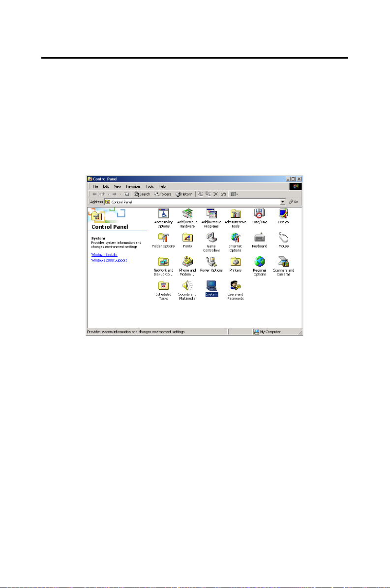
5.6 Windows 2000 Drivers Setup Procedure
Note: The CD-ROM drive is designed as "E" through-
out this section.
1. In the "Windows 2000" screen, click on " Start" and select " settings". Then click on the " Control Panel" icon to select "system".
65 Chapter 5
Page 80
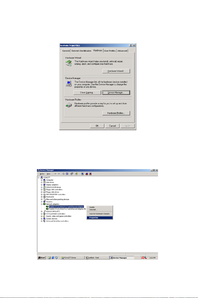
2. In the " System Properties" window, select the " Device Manager".
3. In "Device Manager" screen, follow the screen instructions, to click
on "Properties".
PCA-6005 User’s Manual 66
Page 81
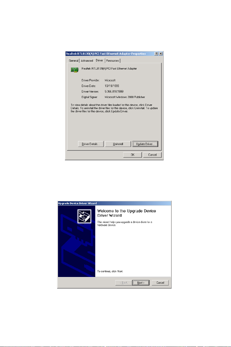
4. In the following screen, to click on "Update Driver".
5. Click on "Next".
67 Chapter 5
Page 82
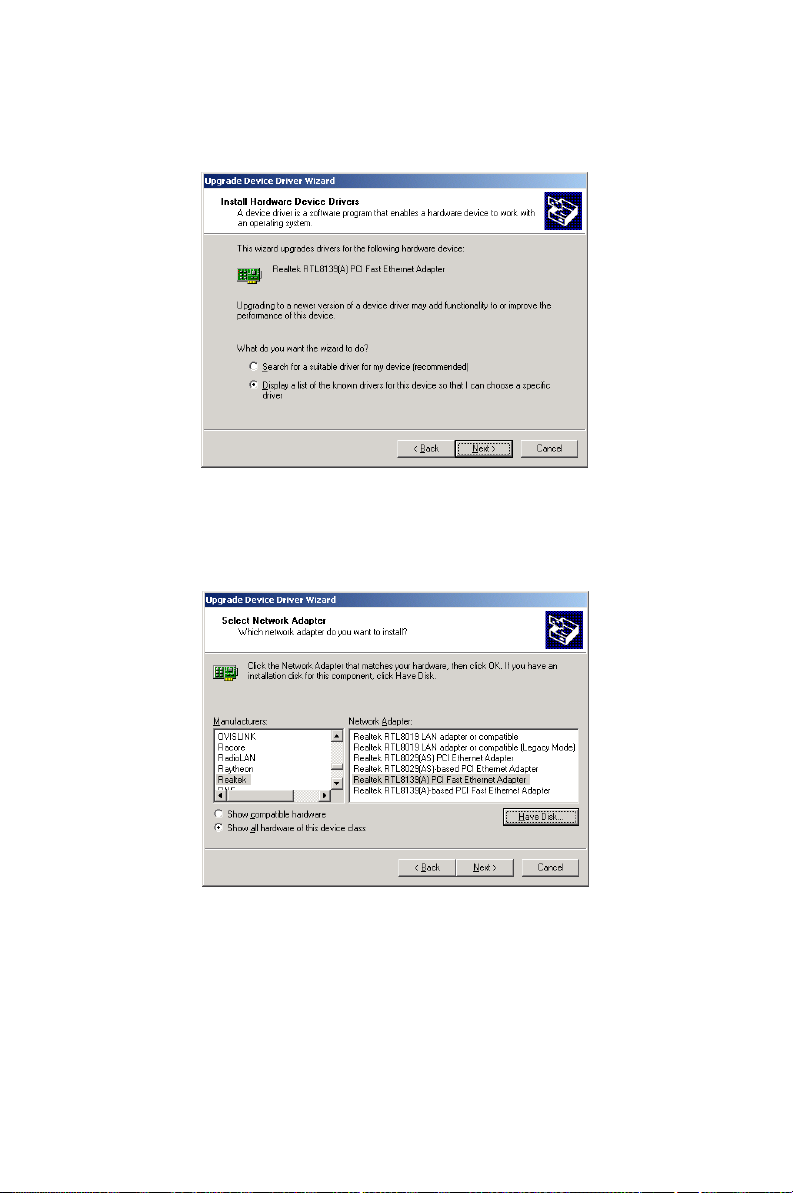
6. Following the highlighted item, and click on "Next".
7. Click on "Have Disk".
PCA-6005 User’s Manual 68
Page 83
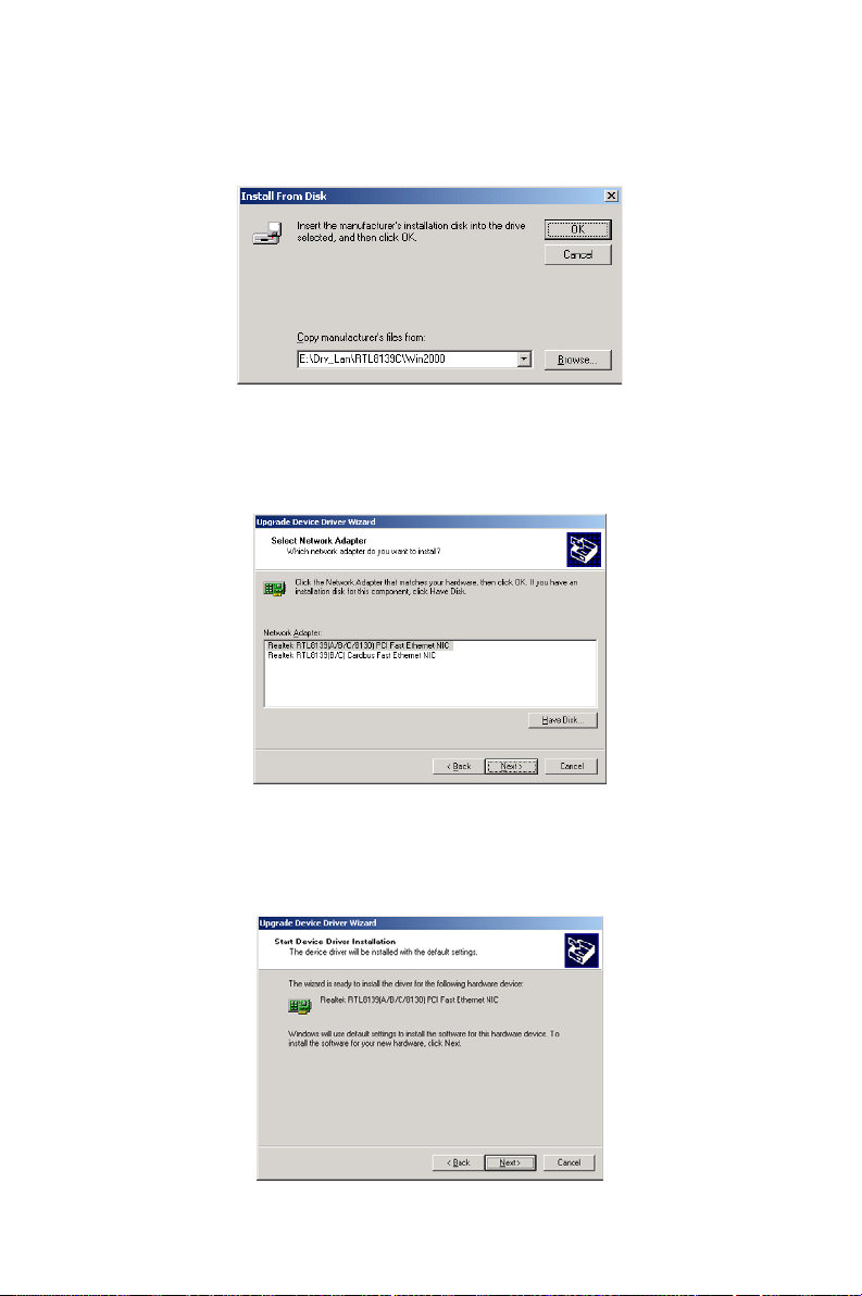
8. Key in "E:\Drv__LAN\RTL8139C\WIN2000", then click on "OK".
9. To highlight the following item, and click "Next".
10. Click "Next".
69 Chapter 5
Page 84
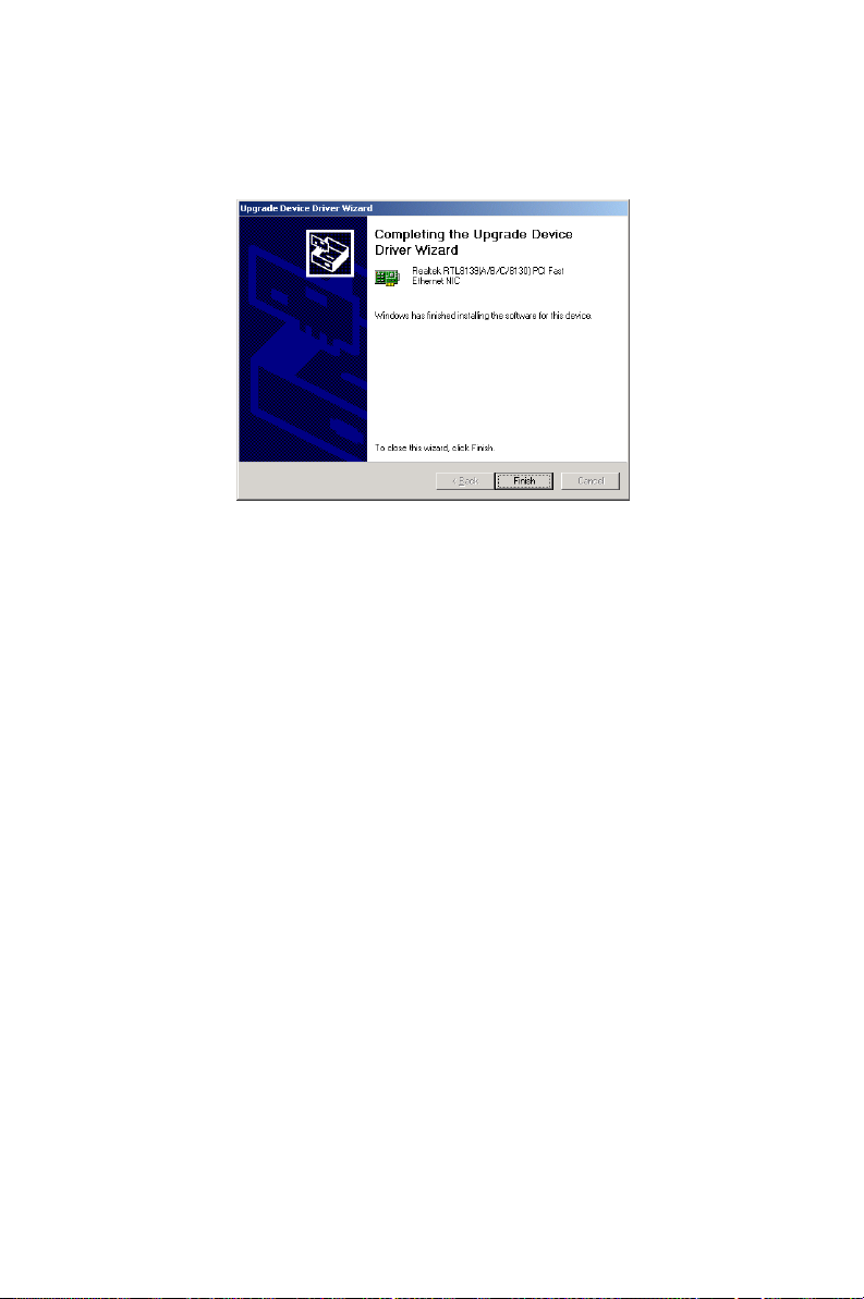
11. Click "Finish" to complete the installation.
PCA-6005 User’s Manual 70
Page 85

6
CHAPTER
SCSI Setup and Configuration
The PCA-6005 features an onboard
SCSI interface. This chapter provides
basic SCSI concepts and instructions
for installing the software drivers with
the SCSI driver disks/CD included in
your package
71
Page 86

Chapter 6 SCSI Setup and Configuration
6.1 Introduction
The PCA-6005 is equipped with an Adaptec AIC-7899 single-chip PCIto-SCSI host adapter which provides a dual channel Ultra 160 multitasking interface between your computer.s PCI bus and SCSI devices
(disk drives, CD-ROM drives, scanners, tape backups, removable media
drives, etc.). Ultra 160 is a new generation of SCSI technology that
expands SCSI performance from 80 MBytes/sec to 160 MBytes/ sec. Up
to a total of 15 SCSI devices can be connected to each of the SCSI connectors.
The AIC-7899 combines this Ultra 160 SCSI technology with Adaptec.s
SpeedFlex. technology. SpeedFlex allows the Adaptec SCSI card to be
backwards compatible with previous generations of SCSI products, while
allowing newer Ultra 160 SCSI devices to operate at the higher 160
MBytes/sec rate.
There are 3 SCSI connectors on the CPU card: CN50 and CN51 for Ultra
160 devices, and CN52 for 50-pin SCSI devices. You can use Ultra 160
and Ultra wide devices simultaneously without compromising the performance.
If you need to configure the SCSI, the onboard SCSI Select configuration
utility allows you to change host adapter settings without opening the
computer or handling the board. The SCSI Select utility also contains a
utility to low-level format and verifies the disk media on your hard disk
drives.
Note: If any peripheral is running at SE mode, the
Ultra 160 SCSI segment will run at speeds up to
40 MBytes/sec only instead of 160 MBytes/sec.
6.2 Understanding SCSI
SCSI (pronounced .scuzzy.) stands for Small Computer Systems Interface. SCSI is an industry standard computer interface for connecting
SCSI devices to a common SCSI bus.
PCA-6005 User’s Manual 72
Page 87

A SCSI bus is an electrical pathway that consists of a SCSI interface
installed in a computer and one or more SCSI devices. SCSI cables are
used to connect the devices to the SCSI interface. For the SCSI bus to
function properly, a unique SCSI ID must be assigned to the SCSI interface and each SCSI device connected to it, and the SCSI bus must be
properly terminated.
6.3 SCSI IDs
Each device attached to the SCSI bus, as well as the SCSI controller
itself, must be assigned a unique SCSI ID number from 0 to 15. A SCSI
ID uniquely identifies each SCSI device on the SCSI bus and determines
priority when two or more devices are trying to use the SCSI bus at the
same time.
Refer o the device.s documentation to set the SCSI ID. Here are some
general guidelines for SCSI IDs:
• For internal SCSI devices, the SCSI ID usually is set by configuring a
jumper on the device.
• For external SCSI devices, the SCSI ID usually is set with a swetch on
the back of the device.
• SCSI ID numbers don.t have to sequential, as long as the SCSI control-
ler and each device has a different number.
• For example, you can have an internal SCSI device with ID 0, and an
external SCSI device with ID 6.
• SCSI ID 7 has the highest priority on the SCSI bus. The priority of the
remianing IDs, in descending order, is 6 to 0, then 15 to 8.
• The on-boards SCSI interface is preset to SCSI ID 7 and should not be
changed. This gives it the highest priority on the SCSI bus.
• Most internal SCSI hard disk drives come from the factory pre-set to
SCSI ID 0.
• If you have 8-bit (or Narrow) SCSI deveices, they must use SCSI IDs 0,
1, 2, 3, 4, 5, or 6. SCSI ID 0 is recommended for the first SCSI hard
disk drive.
• If you are booting your computer from a SCSI hards disk drive con-
nected to the SCSI bus, the Boot SCSI ID setting in the SCSISelect
utility must correspond to the SCSI ID of the device from which you
are booting. By default, the Boot SCSI ID is set to 0. We recommend
that you do not change this setting.
73
Page 88

• In Windowsc 95/98, you can use the Device Manager to determine
which SCSI ID is assigned to each installed SCSI device.
6.4 Terminating the SCSI Bus
To ensure reliable communication on the SCSI bus, the ends of the SCSI
bus must be properly terminated. This is accomplished when the device at
the end of the each cable, or the end of the cable itself, has a terminator
installed (or enabled). Terminators must be removed, or termination must
be disabled, on devices between the ends of each cable.
Since the method for terminating a SCSI device can vary widely, refer to
the device.s documentation for instructions on how to enable or disable
termination. Here are some general guidelines for termination:
• Internal Ultra 160 and Ultra 2 SCSI devices come from the factory with
termination disabled and cannot be changed. Proper termination for
internal Ultra 160 and Ultra2 SCSI devices is provided by a 68-pin
Internal LVD (low voltage differential) SCSI cable, which has a builtin terminator at its end.
• Termination on non-Ultra 160 and Ultra2 internal SCSI devices usually
is controlled by manually setting a jumper or a switch on the device, or
by physically removing or installing one or more resistor modules on
the device.
• Termination on most external SCSI devices is controlled by installing
or removing a SCSI terminator. However, termination on some external SCSI devices is enable or disabled by setting a swetich on the back
of the SCSI device.
The last external Ultra160 or Ultra2 SCSI device must be terminated with
an LVD/SE (low voltage differential/single ended) terminator plug to
ensure that the device will operate at its maximum speed. If you use a different kind of terminator plug, the data I/O rate will decrease.
By default, termination on the SCSI controller itself is set to Automatic
(the preferred method). We recommend that you do not change this
default setting.
6.5 Configuring the SCSI interface with SCSISelect
SCSISelect, included with the CPU card, enables you to change SCSI settings without opening the computer. SCSISelect also enables you to low-
PCA-6005 User’s Manual 74
Page 89
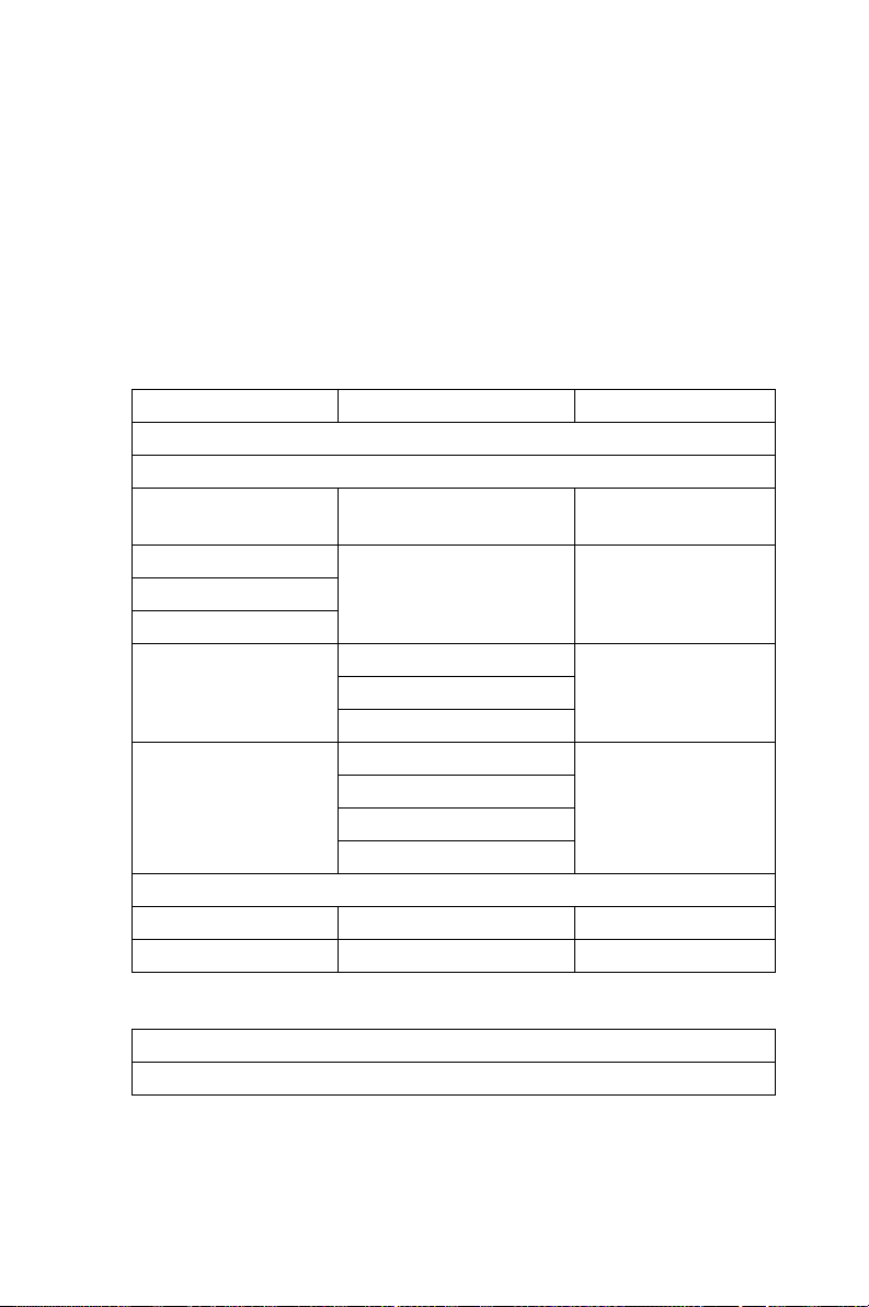
level format or verify the disk media of your SCSI hard disk drives. The
following table lists the available and default settings for each SCSISelect
option.
Note: The default settings are appropriate for most
systems. Run SCSISelect if you need to
change or view current settings, or if you would
like to run the SCSI disk utilities.
SCSISelect Options Available Settings Default Setting
SCSI Bus Interface
Definitions:
Host Adapter SCSI ID0-15 7
SCSI Parity Checking Enable, Disabled Enabled
Host Adapter SCSI
Termination
LVD/SE Connectors Automatic Automatic
Enabled
Disabled
SE Connectors Automatic Automatic
Low On/High On
Low Off/High Off
Low Off/High On
Boot Device Options:
Boot SCSI ID 0-15 0
Boot LUN Number1 0-7 0
SCSI Device Configuration:
Sync Transfer Rate (MBytes/sec)
75
Page 90

160, 80.0, 53.4, 40.0, 160
32.0, 26.8, 20.0,
16.0, 13.4, 10.0
ASYN
Initiate Wide
Negotiation
Enable
Disconnection
Send Start Unit
Command
Enable Write Back
Cache2
BIOS Multiple
LUN Support2
Include in BIOS
Scan2
Advanced Configuration Options:
Reset SCSI Bus at IC
Initialization
Display <Ctrl><A>
Messages during
B IO S In i ti a li z at i on
Extended BIOS
Translation for DOS
Drives > 1 GByte
Verbose/Silent Mode Verbose, Silent Verbose
Host Adapter BIOS Enabled Enabled
Domain Validation2 Enabled, Disabled Enabled
Support Removable
Disks Under BIOS as
Fixed Disks2
BIOS Support for
B o o t a b l e C D _ R O M 2
Yes, No Yes (enabled)
Yes, No Yes (enabled)
Yes, No Yes (enabled)
N/C (No Change) N/C (No Change)
Yes, N o
Yes, No No (disabled)
Yes, No Yes (enabled)
Enabled, Disabled Enabled
Enabled, Disabled Enabled
Enabled, Disabled Enabled
Disabled : Not Scan
Disabled: Scan Bus
Disabled Disabled
Boot Only,
All Disks
Enabled, Disabled Enabled
PCA-6005 User’s Manual 76
Page 91

BIOS Support for
Int 13
Extensions2
1 Setting is valid only if Multiple LUN Support is enabled.
2 Settings are valid only if host adapter BIOS is enabled.
Enabled, Disabled Enabled
6.6 Starting SCSISelect
Follow these steps to start SCSISelect:
1. Turn on or restart your system. During the startup process, pay
careful attention to the messages that appear on your screen.
2. When the following message appears on your screen, press the
Ctrl-A keys simultaneously (this message appearsfor only a few
seconds): Press <Ctrl><A> for SCSISelect (TM) Utility!
3. From the menu that appears, use the arrow keys to move the cursor
to the option you want to select, then press ENTER.
Note: If you have difficulty viewing the display, press
F5 to toggle between color and monochrome
modes. (This feature maye not work on some
monitors.)
Exiting SCSISelect
Follow these steps to exit SCSISelect:
1. Press ESC until a message prompts you to exit (if you changed any
settings, you are prompted to save the changes before you exit.)
At the prompt, select YES to exit, then press any key to reboot the computer. Any changes you made in SCSISelect take effect after the computer boots.
Using SCSISelect Settings
To select an option, use the arrow keys to move the cursor to the option,
then press ENTER. In some cases, selecting an option displays another
meny. You can return to the previous menu at any time by pressing ESC.
To restore the original SCSISelect default values, press F6 from the main
SCSISelect screen
77
Page 92

SCSI Bus Interface Definitions
• Host Adapter SCSI ID-(Default: 7) Sets the SCSI ID for the SCSI
controller. The Adaptec SCSI controller AIC-7899 is set at 7, which
gives t the highest priority on the SCSI bus. We recommend that you
do not change this setting.
• SCSI Parity Checking-(Default: Enabled) When set to Enabled, veri-
fies the accuracy of data transfer on the SCSI bus. Leave this setting
enabled unless any SCSI device does not support SCSI parity.
• Host Adapter SCSI Termination-(Default: Automatic) Determines
the termination setting for the SCSI card. The default setting for both
the LVD/SE (low voltage differential/single ended) connectors and SE
connectors is Automatic, which allows the SCSI card to adjust the termination as needed depending on the configuration of the connected
SCSI devices. We recommend that you do not change these settings.
Boot Device Options
• Boot SCSI ID-(Default: 0) Specifies the SCSI ID of your boot
device. We recommend that you dono t change the default setting.
• Boot LUN Number-(Default: 0) Specifies which LUN (Logical Unit
Number) to boot from on your boot device. This setting is not valid
unless Multiple LUN Support is Enabled
SCSI Device Configuration
SCSI Device Configuration options can be set individually for each connected SCSI device.
Note: To configure settings for a SCSI device, you
must know it.s SCSI ID
• Sync Transfer Rate-(Default: 160) Determines the maximum syn-
chronous data transfer rate that the SCSI card supports. Use the mazimum value of 160 MBytes/sec.
• Initiate Wide Negotiation-(Default: Yes) When set to Yes, the SCSI
card attempts 16-bit data transfer (wide negotiation.) When set to No,
the SCSI card uses 8-bit data transfer unless the SCSI device requests
wide negotiation.
PCA-6005 User’s Manual 78
Page 93

Note: Set Initiate Wide Negotiation to NO if you are
using an 8-bit SCSI device that hangs or exhibits other performance problems with 16-bit data
transfer rate enabled.
• Enable Disconnection-(Default: Yes) When set to Yes, allows the
SCSI device to disconnect from the SCSI bus. Leave the setting at
Yes if two or more SCSI device is connected, changing the setting to
No results in slightly better performance.
• Send Start Unit Command-(Default: Yes) When set to Yes, the Start
Unit Command is sent to the SCSI device at bootup.
The following three options have no effect if the SCSI Card BIOS is disabled. (The SCSI Cards BIOS is normally enabled by default.)
• Enable Write Back Cache-(Default: N/C) Can be used to enable or
disable the write-back cache on SCSI disk drives connected to the host
adapter. Leave this option at its default setting of N/C (no change),
which usually allow for optimum drive performance.
• BIOS Multiple LUN Support-(Default: No) Leave this setting at No if
the device does not have multiple Logical Unit Numbers (LUNs.)
When set to Yes, the SCSI card BIOS provides boot support for a SCSI
device with multiple LUNs (for example, a CD juke box. device in
which mulitple CDs can be accessed simultaneously.)
• Include in BIOS Scan-(Default: Yes) When set to Yes, the SCSI card
BIOS includes the device as part of its BIOS scan at bootup.
Advanced Configuration Options
Note: Do not change the Advanced Configuration
Options unless absolutely necessary.
• Reset SCSI Bus at IC Initialization-(Default: Enabled) When set to
Enabled, the SCSI card generates a SCSI bus reset during its power-on
initialization and after a hard reset.
• Display <Ctrl> <A> Messages during BIOS Initialization-(Default:
Enabled) When set to Enabled, the SCSI card BIOS displays the Press
<Ctrl> <A> for SCSISelect (TM) Utility! message on your screen during system bootup. If this setting disabled, you can still invoke the
79
Page 94

SCSISelect Utility by pressing <Ctrl> <A> after the SCSI card BIOS
banner appears.
• Extended BIOS Translation for DOS Drives > 1 GByte-(Default:
Enabled) When set to Enabled, provides an extended translation
scheme for SCSI hard disks with capacities greater than 1 GByte.
This setting is necessary only for MS-DOS 5.0 or above; it is not
required for other operating systems, such as NetWare of UNIX.
Caution: Changing the translation scheme destroys all
data on the drive. Bue sure to back your disk
drives before changing the translation scheme.
Use the MS-DOS Fdisk command to partition a disk laster than 1GByte
controlled by the SCSI card BIOS, when using DOS, Windows 3.1.x, ro
Windows 95/98.
• Verbose/Silent Mode-(Default: Verbose) When set to Verbose, the
SCSI card BIOS displays the host adapter model on the screen during
sustem buildup. When set to Silent, the message is not displayed during bootup.
• Host Adapter BIOS (Configuration Utility Reserves BIOS Space)-
(Default: Enabled) Enables or disables the SCSI card BIOS.
• Leave at Enabled to allow the SCSI card BIOS to scan and initialize all
SCSI devices.
• Set to Disabled: Not scan if the devices on the SCSI bus (for example,
CD-ROM drives) are controlled by software drivers and do not need
the BIOS, and you do not want the BIOS to scan the SCSI bus.
• Set to Disabled: Scan Bus if you do not need the BIOS, but you want it
to scan the SCSI devices on the bus and you need to spin up the
devices.
The following four options have no effect when the SCSI Card BIOS is
disabled. (The SCSI Card BIOS is normally enabled by default.)
• Domain Validation.(Default: Enabled) Determines the optimal transfer
rate for each device on the SCSI bus and sets transfer rates accordingly.
Displays the resulting data transfer rate.
• Support Removable Disks Under BIOS as Fixed Disks. (Default:
Disabled) Determines which removable-media drives are supported by
the SCSI card BIOS. Choices are as follows:
PCA-6005 User’s Manual 80
Page 95

• Disabled. No removable-media drives are treated as hard disk drives.
Software drivers are required because the drives are not controlled by
the BIOS.
• Boot Only.Only the removable-media drive designated as the boot
device is treated as a hard disk drive.
• All Disks.All removable-media drives supported by the BIOS are
treated as hard disk drives.
Caution: You may lose data if you remove a removable-
media cartridge from a SCSI drive controlled by
the SCSI card BIOS while the drive is on. If you
want to be able to remove the media while the
drive is on, install the removable-media software driver and set Support Removable Disks
Under BIOS as Fixed Disks to Disabled.
• BIOS Support for Bootable CD-ROMs.(Default: Enabled) When set
to Enabled, the SCSI card BIOS allows the computer to boot from a
CD-ROM drive.
• BIOS Support for Int 13 Extensions.(Default: Enabled) When set to
Enabled, the SCSI card BIOS supports Int 13h extensions as required
by Plug-and-Play. The setting can be either enabled or disabled if your
system is not Plug-and-Play.
6.7 Using SCSI Disk Utilities
To access the SCSI disk utilities, follow these steps:
1. Select the SCSI Disk Utilities option from the menu that appears
after starting SCSISelect. SCSISelect scans the SCSI bus (to determine the devices installed) and displays a list of all SCSI
6.8 Installation under Windows NT/Windows 2000
If you are only using SCSI hard drives without any IDE HDD drive
installed. Please follow these steps:
1. Insert Windows NT/Windows 2000 CD Disk.
81
Page 96
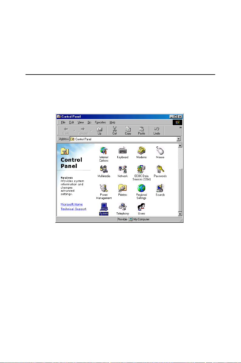
2. Press F6 immediately when it displays: “Set up is inspecting your
computer’s hardware configuration.”
3. Then it enter SCSI installation. Please insert SCSI driver floppy
disk.
6.9 Windows 9X Driver setup procedure
1. In the window 9x screen, click on “start” and select “setting”. Then
click on the “Control Panel” icon to select .System.
PCA-6005 User’s Manual 82
Page 97
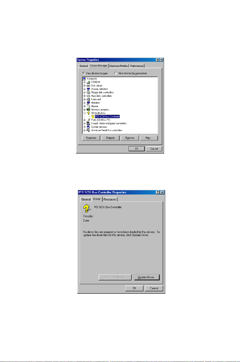
2. In the “System properties”, choose “PCI SCSI Bus Controller.”
Then click on “Properties.”
3. Click on "Update Driver"
83
Page 98
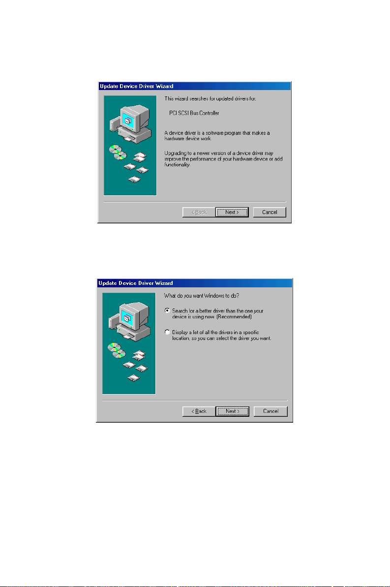
4. Click on “Next”
5. Recommend to search for a better driver
PCA-6005 User’s Manual 84
Page 99
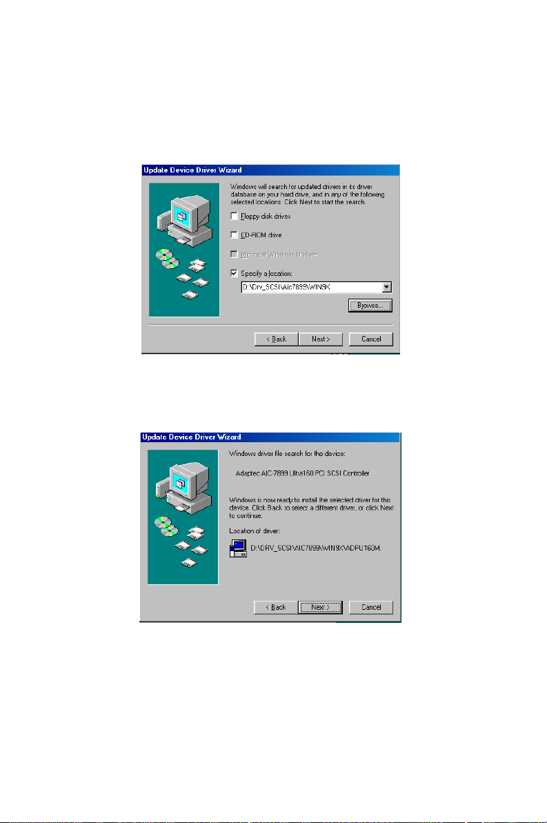
6. If the SCSI driver is supplied in floppy disk, click on “Floppy disk
drives.” Then, click on “Next.” If the SCSI driver is supplied in
CD-ROM disk, click on “Specify a location:" then enter
"E:\Drv_SCSI\AIC7899\Windows\Win9X"
7. In the "Update Device Driver Wizard" click on "Next."
85
Page 100
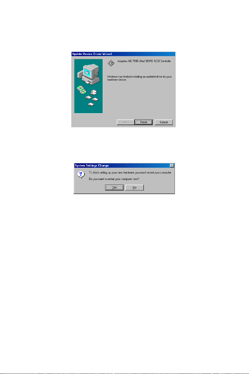
8. The installation is completed. Click on "Finish."
9. Click on "Yes" to restart the system.
PCA-6005 User’s Manual 86
 Loading...