

Paxton Superchargers V-10 User Manual

DP/N: 4800019 - Dodge V-10 v2.0 09/25/03
Kit # 1201210
Owners Installation Guide for the
Paxton Automotive
NOVI 2000 Supercharger
for the
1994-2001 Dodge
V-10 Truck
PAXTON Automotive . 1300 Beacon Place . Oxnard CA 93033
(888) 9-PAXTON . FAX (805) 247-0669
S U P E R C H A R G E R S
ii
P/N: 4800019
©2003 Paxton Automotive
All Rights Reserved, Intl. Copr. Secured
25SEP03 v2.0 Dodge V-10(4800019v2.0)
T
his manual provides information on the installation, maintenance and servicing of the Paxton
NOVI-2000 Supercharger kit expressly designed for the 1994-2001 Dodge V-10 truck. Contact
Paxton for information regarding these modifications at (805)604-1336 7:00 a.m.-3:30p.m.
PST.
An understanding of the information contained herein will help novices as well as experienced technicians to correctly install and receive the greatest possible benefit from their Paxton Supercharger.
When reference is made in this manual to a brand name, number or specific tool or technique, an
equivalent product may be used in place of the item mentioned. All information, illustrations and
specifications contained herein are based on the latest product information available at the time of the
publication. The right is reserved to make changes at any time without notice.
KIT P/N: 1201210
© 2003 PAXTON AUTOMOTIVE
All rights recerved. No parts of this publication may be reproduced, transmitted, transcrived, or translated into
another language in any form, by any means without written permission of Paxton Automotive.

iii
P/N: 4800019
©2003 Paxton Automotive
All Rights Reserved, Intl. Copr. Secured
25SEP03 v2.0 Dodge V-10(4800019v2.0)
TABLE OF CONTENTS
FOREWORD . . . . . . . . . . . . . . . . . . . . . . . . . . . . . . . . . . . . . . . . . . . . . . . . . . . . . . . . .2
TABLE OF CONTENTS . . . . . . . . . . . . . . . . . . . . . . . . . . . . . . . . . . . . . . . . . . . . . . . . .TC-I
1.0 INTRODUCTION . . . . . . . . . . . . . . . . . . . . . . . . . . . . . . . . . . . . . . . . . . . . . . . .1-1
2.0 INITIAL PREPARATION AND DISASSEMBLY . . . . . . . . . . . . . . . . . . . . . . . .2-1
3.0 SUPERCHARGER INSTALLATION AND ASSEMBLY . . . . . . . . . . . . . . . . . .3-1
4.0 ADDITIONAL INJECTOR CONTROLLER INSTALLATION. . . . . . . . . . . . . . .4-1
5.0 FINAL CHECK AND START-UP . . . . . . . . . . . . . . . . . . . . . . . . . . . . . . . . . . . . .5-1
APPENDICES
Appendix A PARTS LIST . . . . . . . . . . . . . . . . . . . . . . . . . . . . . . . . . . . . . . . . . . . . .A-2
Appendix B ASY, NOVI 2000 SUPERCHARGER . . . . . . . . . . . . . . . . . . . . . . . . . .A-3
Appendix C ASY, SUPERCHARGER MOUNTING BRACKET . . . . . . . . . . . . . . .A-4
Appendix D ASY, CRANK PULLEY . . . . . . . . . . . . . . . . . . . . . . . . . . . . . . . . . . . .A-5
Appendix E ASY, AIR INTAKE . . . . . . . . . . . . . . . . . . . . . . . . . . . . . . . . . . . . . . . .A-6
Appendix F ASY, AIR DISCHARGE . . . . . . . . . . . . . . . . . . . . . . . . . . . . . . . . . . . .A-7
Appendix G ASY, COMPRESSOR BYPASS . . . . . . . . . . . . . . . . . . . . . . . . . . . . . . .A-8
Appendix H ASY, SPRING LOADED TENSIONER . . . . . . . . . . . . . . . . . . . . . . . .A-9
Appendix I ASY, AUXILIARY FUEL SYSTEM . . . . . . . . . . . . . . . . . . . . . . . . . . .A-10
Appendix J ASY, FUEL ENRICHMENT . . . . . . . . . . . . . . . . . . . . . . . . . . . . . . . . .A-11
Appendix K ASY, OIL SUPPLY AND RETURN . . . . . . . . . . . . . . . . . . . . . . . . . . . .A-12
Appendix L ASY, HEATER HOSE RELOCATION . . . . . . . . . . . . . . . . . . . . . . . . .A-13
Appendix M RADIATOR HOSE EXTENSION ASSEMBLY . . . . . . . . . . . . . . . . . . .A-14
Appendix N ASY, WASHER BOTTLE RELOCATION . . . . . . . . . . . . . . . . . . . . . . .A-15

iv
P/N: 4800019
©2003 Paxton Automotive
All Rights Reserved, Intl. Copr. Secured
25SEP03 v2.0 Dodge V-10(4800019v2.0)
This Page Left Intentionally Blank

P/N: 4800019
©2003 Paxton Automotive
All Rights Reserved, Intl. Copr. Secured
25SEP03 v2.0 Dodge V-10(4800019v2.0)
1-1
C
ongratulations! You have purchased the
finest street supercharger available for the
1994-2001 Dodge V-10 truck. The centerpiece of the kit is the highly efficient and reliable PAXTON NOVI-2000 supercharger - a
mechanically driven (by belt) centrifugal blower
(supercharger).
This kit comes with all of the parts you’ll need
for a successful installation. The operations
required have been grouped in order of
sequence. Photos and drawings accompany the
text, allowing quick orientation and parts identification.
Installation requires a selection of tools which
are listed in a table at the end of this section.
We also suggest that you obtain a Dodge truck
shop manual and become familiar with the
details of your car’s systems. Manuals may be
obtained from your local Dodge dealer or you
can order one from Helm Publications at (800)
782-4356.
For best results, follow the instructions closely
and in sequence. The average installation time
for this kit is 8-10 hours. Your actual installation
time will depend on skill level and working conditions. The estimate does not include time for
initial vehicle inspection, cleaning, fine tuning
or troubleshooting. Before even picking up a
wrench, read this entire manual. We are avail-
able for technical assistance at (805) 6041336, 7 AM-3:30 PM Pacific Time.
After reading the manual, verify that all major
assembly groups are present in the main kit box.
You should have ample space to lay out the
components. As you remove a box or bag from
the main kit, note the identification label and
compare it with the parts list. Please check the
box for small parts.
Paxton makes every effort to insure that all parts
are included in the box. However, if you discov-
er any missing or mislabeled parts, please contact Paxton by phone for service.
***** WARNING *****
DO NOT attempt installation if any part(s)
are missing from this kit. Failure to contact
Paxton prior to beginning installation will
result in a charge for any missing parts.
Before starting the installation, we suggest your
engine and engine compartment be clean. You
can clean the engine and compartment with a
pressure washer (such as those used at self-serve
car washes) and a safe-for-aluminum
cleaner/degreaser. Cover the distributor with a
plastic bag to prevent water from entering.
***** CAUTION *****
We do not recommend proceeding with
the kit installation unless your vehicle is
within normal operating parameters.
You are undoubtedly enthusiastic about getting
started on your project, but take just a little more
time to insure that your safety is not jeopardized. A moment’s lack of attention can result in
an accident, as can failure to observe certain
simple safety precautions. The possibility of an
accident will always exist, and the following
points should not be considered a comprehensive list of all dangers. Rather, they are intended
to make you aware of the risks and to encourage
a safety conscious approach to all work you do
on your vehicle.
• Never rely solely on a jack when working
under a vehicle. Always use approved jackstands to support the vehicle and place them
under the recommended lift points.
• When jacking the vehicle, make sure it is on
a level surface, preferably concrete or
asphalt. The transmission should be in
Section 1.0
INTRODUCTION

1-2
“PARK” or “FIRST”, the parking brake
engaged, and the wheels blocked.
• Never start the car without first verifying
that the transmission is in neutral and the
parking brake is set.
• Never remove the radiator cap while the
engine is still hot.
• Always wear eye protection when using
power tools such as drills, saws, grinders,
etc., or when working under a vehicle.
• Never smoke, use an open flame, or have
spark-producing items around gasoline or
flammable solvents. Always have a fire
extinguisher rated for chemical and electrical
fires handy when working on motor vehicles.
• Run engines only in a well ventilated area.
Carbon monoxide, gasoline and solvent
vapors are colorless, and sometimes odorless. These can asphyxiate or explode without warning.
• Always disconnect at least the (-) negative or
ground terminal of the battery when doing
any electrical, fuel system, or under-dash
work.
We look forward to hearing from you, particularly if you have any comments or suggestions
regarding this manual.
NOTE: Throughout these procedures the word
“discard” is used periodically in relationship
to items that will no longer be utilized in
conjunction with the supercharger installation. It is recommended that these items
be saved for future use should it become
necessary.
P/N: 4800019
©2003 Paxton Automotive
All Rights Reserved, Intl. Copr. Secured
25SEP03 v2.0 Dodge V-10(4800019v2.0)
RREECCOOMMMMEENNDDEEDD
TTOOOOLLSS FFOORR
IINNSSTTAALLLLAATTIIOONN::
9/16” Wrench
3/8” Ratchet
9/16” Socket 3/8” Drive
5/8” Socket 3/8” Drive
Pliers
Hacksaw
Wire Cutters
13mm Socket 3/8” Drive
10mm Socket
Long Extension
Wire Crimper/Strippers
13mm Wrench
Medium Extension
Drill Motor
1/8” Drill Bit
13/64” Drill Bit”
1/4” Drill Bit
5/16” Nut Driver or Slot Screwdriver
1/4” Allen Wrench or Socket
3/4” Socket
8mm Wrench
Hose Cutter or Sharp Knife
#2 Phillips Screwdriver
13mm Socket 3/8” Drive
Air Chisel/Hammer
Harmonic Balancer Puller
Power Steering Pulley/Puller Installer
Section 2.0
INITIAL PREPARATION AND DISASSEMBLY
2-1
P/N: 4800019
©2003 Paxton Automotive
All Rights Reserved, Intl. Copr. Secured
25SEP03 v2.0 Dodge V-10(4800019v2.0)
Fig 2-a
Fig 2-b
Fig 2-c
I
n this section, you will be preparing for the
installation procedure by disconnecting the
battery cables and removing and relocating
a few pieces to make room for your new
Paxton supercharger.
2.1 INITIAL DISASSEMBLY AND
REMOVAL:
A. With a 1/2” wrench, remove both bat-
tery cables.
B. An 8mm wrench or socket is used to
remove the battery hold-down. Lift the
battery out of the tray and set it aside.
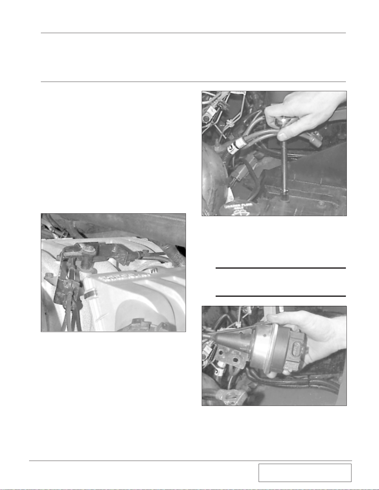
C. Unclip the cruise control cable from the
throttle body and mount if equipped.
(See Fig. 2-a.)
D. The tray is secured with two bolts and
two nuts above and two more accessible
from below. Use a 13mm socket with an
extension, and raise the battery tray
from the vehicle. (See Fig. 2-b.)
E. Use a 10mm wrench and remove the
cruise control actuator from the bottom
of the battery tray. Later it will be modified and reinstalled. (See Fig. 2-c.).
*** NOTE ***
On some later model trucks, the factory relocated
the cruise control actuator so this step will not need
to be done.
2-2
P/N: 4800019
©2003 Paxton Automotive
All Rights Reserved, Intl. Copr. Secured
25SEP03 v2.0 Dodge V-10(4800019v2.0)
Fig 2-d
Fig 2-e
Fig 2-f
Fig 2-g
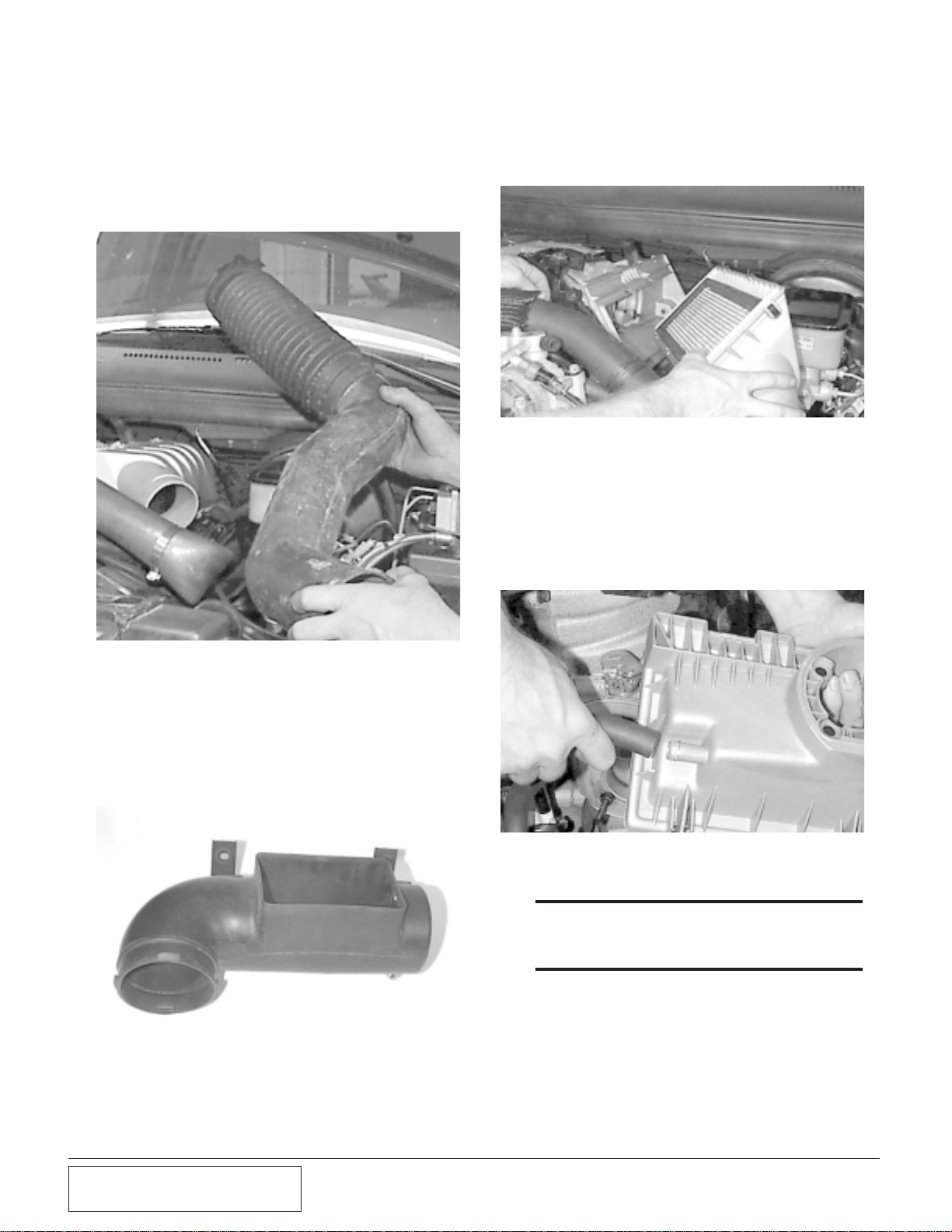
C. Unclip the air cleaner assembly from its
base and remove it along with the air filter element. (See Fig. 2-f.)
B. There are two bolts securing the air horn
to the core support. From the front of
the core support, use a 10mm socket and
remove the horn from the core support.
You will have to bend the bracket in
order to remove it. (See Fig. 2-e.)
2.2 AIR INTAKE ASSEMBLY:
A. Disconnect the plastic duct from
between the air cleaner assembly and
the air horn on the radiator core support
(See Fig. 2-d.).
D. Use a 7/16” deep socket and remove
the four nuts securing the air cleaner
base to the throttle body.
E. Pull the base away from the throttle
body and disconnect the crankcase vent
hose from it. Set it aside, it will not be
reused. (See Fig. 2-g.)
2.3 FAN AND FAN SHROUD:
***WARNING***
Clean up any anti-freeze spillage immediately.
Animals like the taste of coolant, and if ingested
they can become very sick, and even die.
A. With a pair of pliers, remove the lower
radiator hose and drain the coolant from
the vehicle. Replace the hose and resecure with the factory clamp.
2-3
P/N: 4800019
©2003 Paxton Automotive
All Rights Reserved, Intl. Copr. Secured
25SEP03 v2.0 Dodge V-10(4800019v2.0)
Fig 2-h
Fig 2-i
Fig 2-j
Fig 2-k
B. Disconnect the upper radiator hose and
fold it back out of the way.
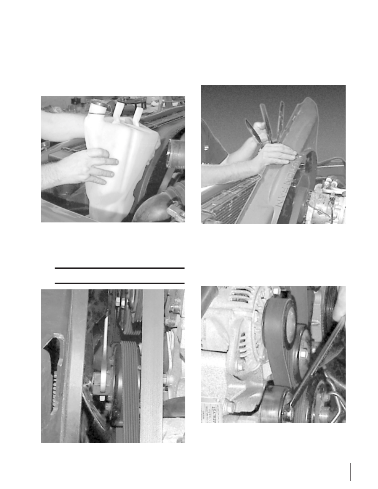
C. Unclip the window washer bottle from
the shroud. Lift the bottle and disconnect the two plugs and the hose from the
bottle. Set it aside. (See Fig. 2-h.)
D. With a 36mm wrench or large crescent
wrench, loosen the fan and remove it
from the water pump. Set it into the fan
shroud.
*** NOTE ***
This nut has right hand threads. (See Fig. 2-i.)
E. Remove the four screws securing the
shroud to the radiator using a 10mm
socket. Lift the shroud and fan out of the
engine compartment together. (See Fig.
2-j.).
2.4 POWER STEERING BRACKET:
A. Use a 16mm wrench, turn the belt ten-
sioner counter clockwise and remove the
stock accessory drive belt. (See Fig.
2-k.)

2-4
P/N: 4800019
©2003 Paxton Automotive
All Rights Reserved, Intl. Copr. Secured
25SEP03 v2.0 Dodge V-10(4800019v2.0)
Fig 2-l
Fig 2-m
Fig 2-n
Fig 2-o
B. Follow the accompanying instructions
with the power steering pulley
puller/pusher and remove the power
steering pulley. (See Fig. 2-l.)
C. Use a 15mm socket and remove the
three bolts securing the pump to the
bracket. (See Fig. 2-m.)
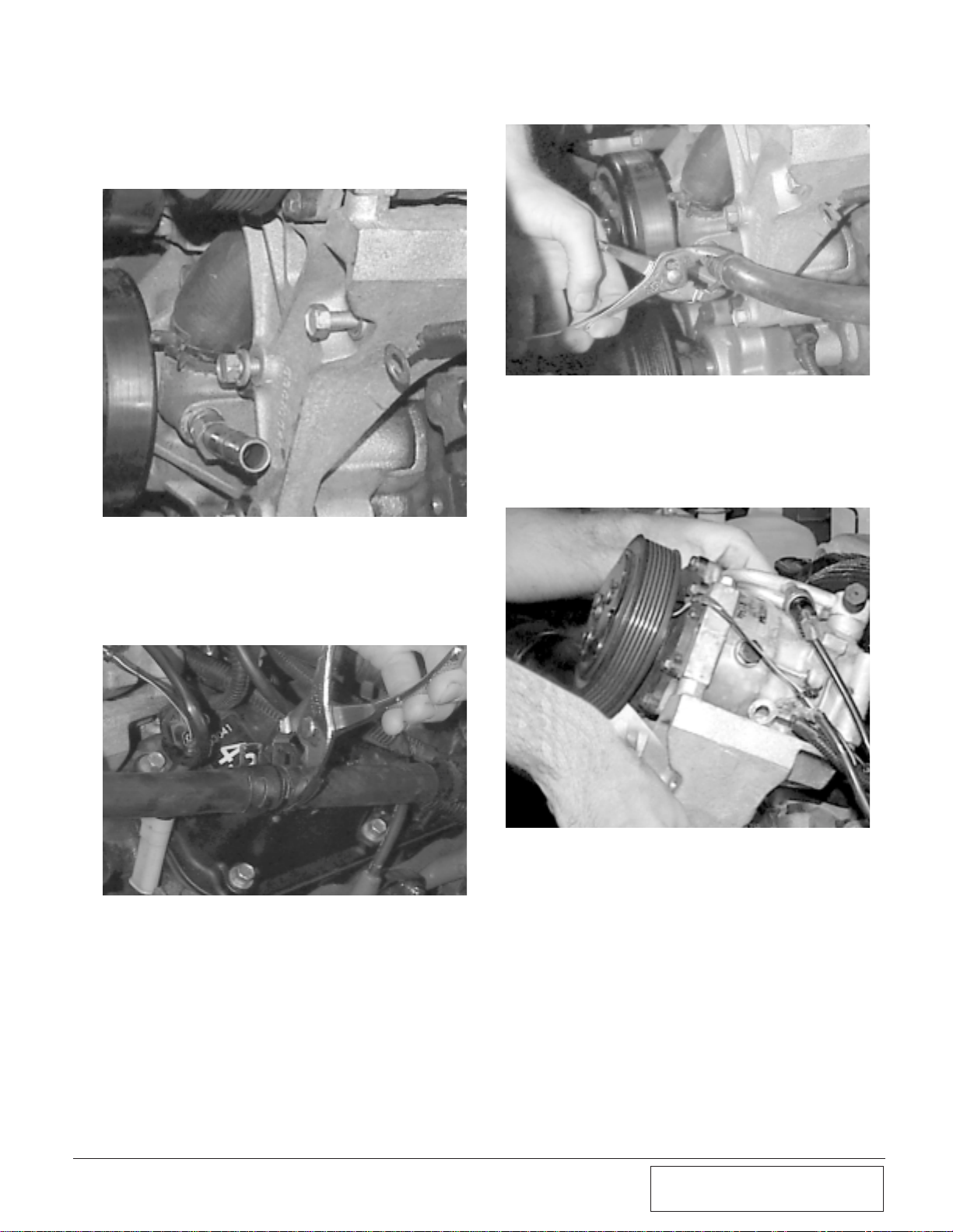
D. With a 9/16” socket and extension,
remove the four bolts that secure the
power steering bracket to the engine. Do
not disconnect the fluid lines.
E. On the back of the pump, remove the
two nuts with a 15mm wrench and the
two bolts with a 12mm socket. Remove
the bracket from the pump and lay the
pump on the steering box. Grab the
power steering pump with both hands.
Bend the pressure line down until it is
flat, as shown. (See Fig. 2-n.)
F. Remove the bolt from the upper rod on
the A/C compressor with a 1/2” socket.
(See Fig. 2-o.)
DODGE V-10
POWER STEERING
PUMP HOSE
FLATTEN OUT
BEND IN
METAL LINE
BEND DOWN
MODIFICATION
P/S/PUMP
REAR VIEW
METAL LINE
SHOULD
LOOK LIKE
THIS AFTER
BENDING.
TOP VIEW
CAP
2-5
P/N: 4800019
©2003 Paxton Automotive
All Rights Reserved, Intl. Copr. Secured
25SEP03 v2.0 Dodge V-10(4800019v2.0)
Fig 2-p
Fig 2-q
Fig 2-r
Fig 2-s
G. With a 9/16” socket, remove the four
bolts securing the A/C bracket to the
head. (See Fig 2-p.)
H. With a pair of pliers, disconnect the
heater hose at the splice. Then, remove
the hose at the nipple on the side of the
water pump. (See Figs 2-q, 2-r.)
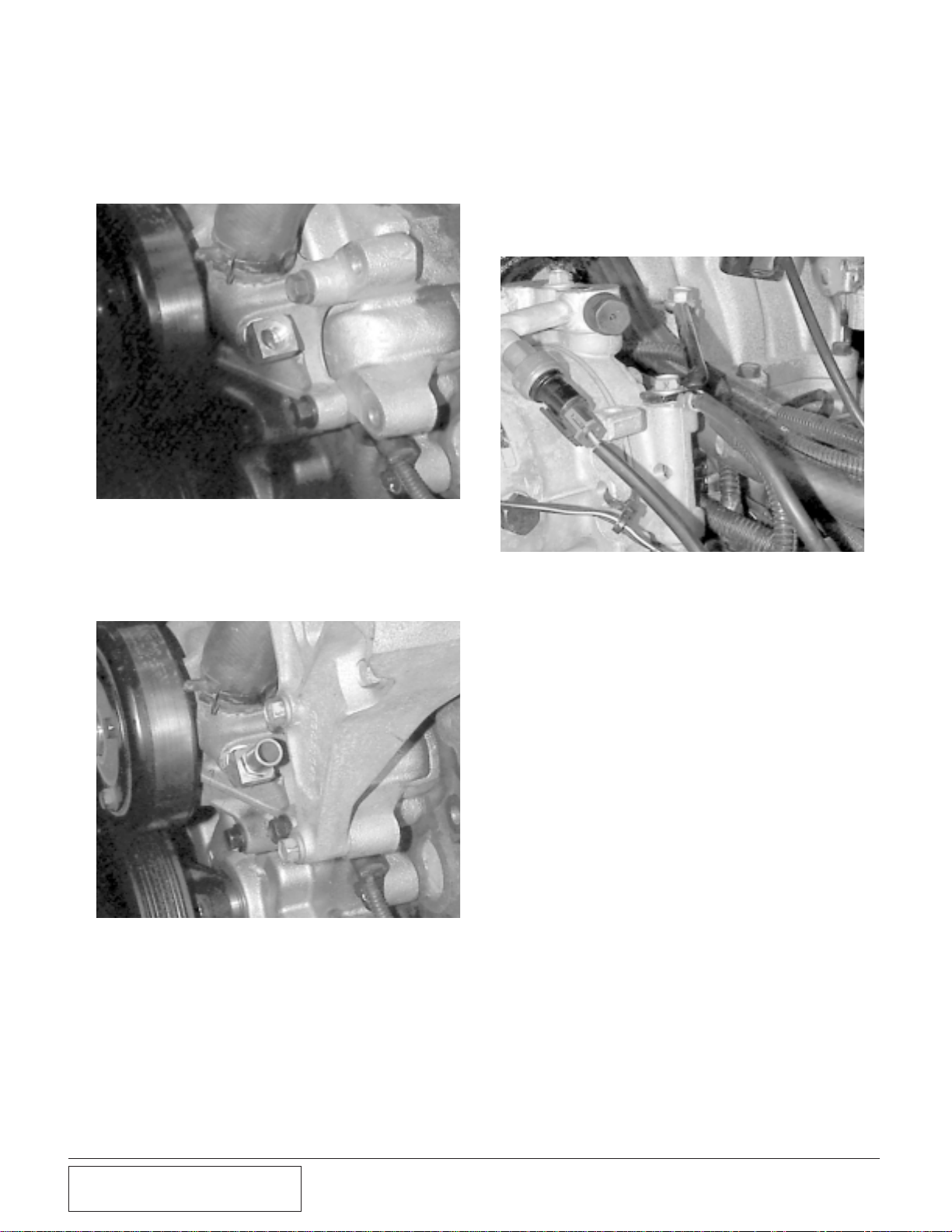
I. Lift the A/C bracket up and out of the
way. Remove the long heater hose nipple from the water pump with a 3/4”
wrench. (See Fig. 2-s.)
2-6
P/N: 4800019
©2003 Paxton Automotive
All Rights Reserved, Intl. Copr. Secured
25SEP03 v2.0 Dodge V-10(4800019v2.0)
Fig 2-t
Fig 2-u
Fig 2-v
J. Install the 45º brass elbow into the water
pump and tighten with a 13/16” wrench.
Use Teflon tape and position as shown.
(See Fig. 2-t.)
L. Reinstall the A/C bracket using the stock
bolts. When resecuring the rod to the top
of the compressor, secure the two
ground wires previously secured to the
power steering pump bracket. Install the
wires between the rod and the compressor. (See Fig. 2-v.)
K. Install the brass nipple into the fitting
installed in step 2-t with Teflon tape and
tighten with a 5/8” wrench. (See Fig.
2-u and Appendix M.)
Section 3.0
SUPERCHARGER INSTALLATION AND ASSEMBLY
Fig 3-a
Fig 3-b
Fig 3-c
C. Use the supplied wire, wire loom and
butt connectors to extend the factory
harness to the cruise control module.
Cut off the plug leaving about 6” of
wire.
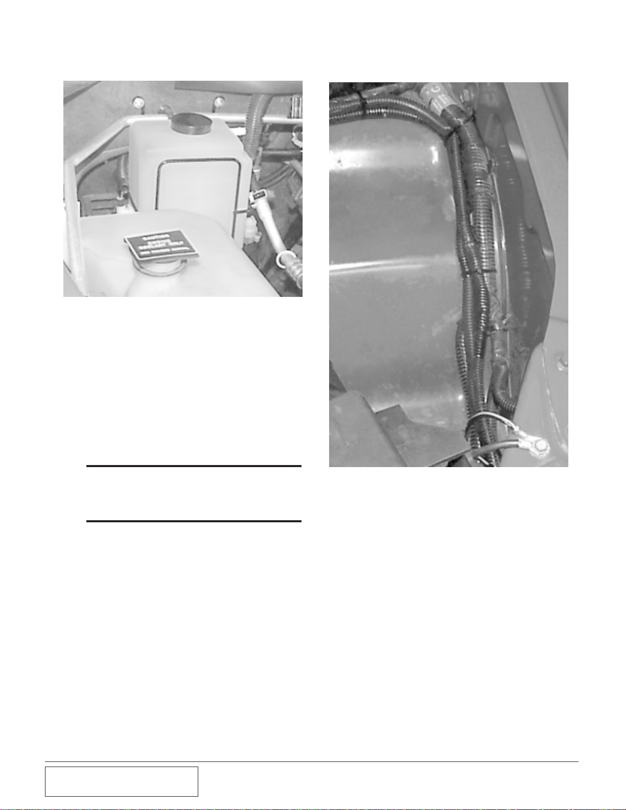
3.2 WINDOW WASHER BOTTLE
A. The washer bottle will be mounted on
the passenger side firewall. The wire
bracket must be bent in order for the
bottle to clear the A/C line running
across the firewall in that area. Bend an
offset in the bracket, set it in place and
mark the mounting holes. Use a 1/8”
drill and drill the two mounting holes.
(See Fig. 3-d.)
B. Secure the cruise control to the two
screws that secure the windshield wiper
motor, near the firewall and the washer
bottle. (See Fig 3-c.)
N
ow we start modifying various electrical
and mechanical assemblies as well as
beginning the supercharger installation.
***NOTE***
On some later model vehicles, this step will not
apply.
3.1 MODIFICATION AND INSTALLA-
TION
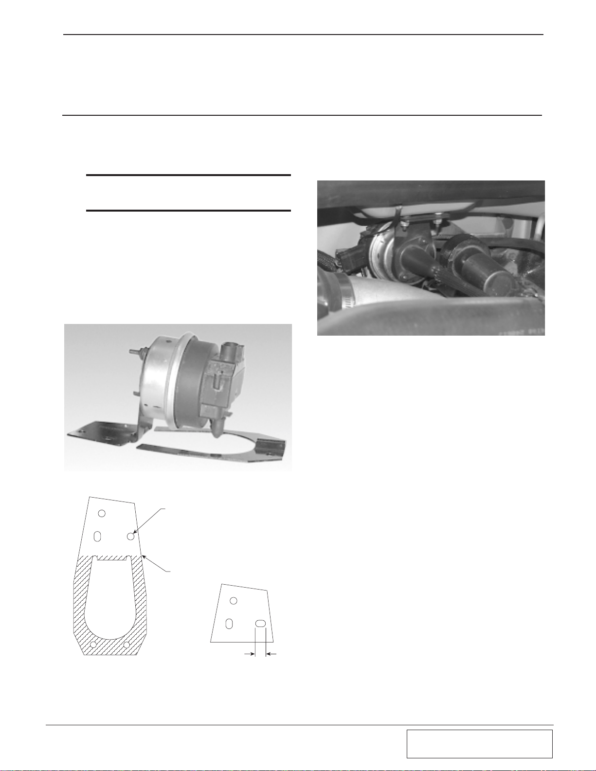
A. Modify the previously removed Cruise
Control bracket as shown.(See Figs. 3-a,
3-b.) It is not necessary to remove the
Cruise Control Actuator from the bracket.
3-1
P/N: 4800019
©2003 Paxton Automotive
All Rights Reserved, Intl. Copr. Secured
25SEP03 v2.0 Dodge V-10(4800019v2.0)
LENGTHEN THIS HOLE
CUT LINE
.2
MODIFIED BRACKETORIGINAL PART
3-2
P/N: 4800019
©2003 Paxton Automotive
All Rights Reserved, Intl. Copr. Secured
25SEP03 v2.0 Dodge V-10(4800019v2.0)
Fig 3-e
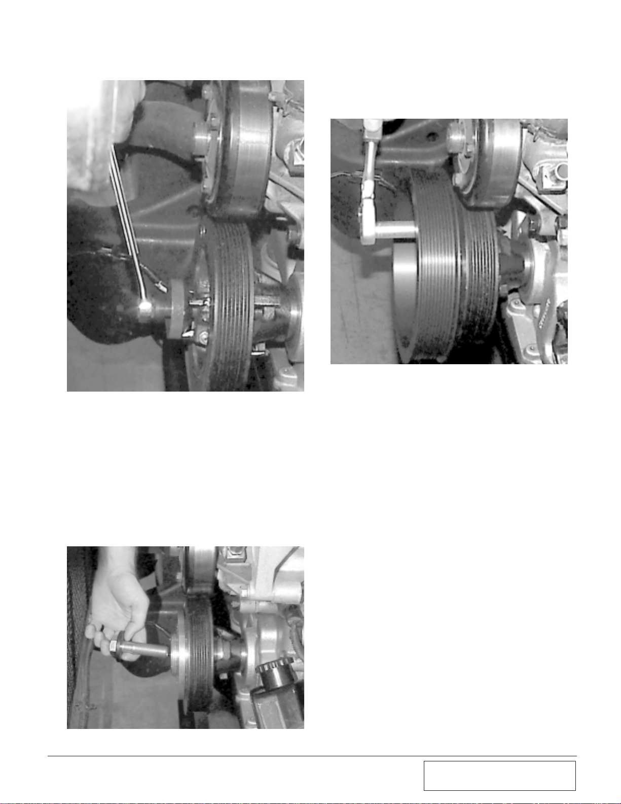
3.3 CRANK PULLEY:
A. Using a 1-1/8” socket remove the large
center bolt from the crank pulley.
B. With an adequate puller, pull the crank
pulley off of the crank shaft. (See Fig.
3-f.)
Fig 3-d
B. Remove the pump and sensor from the
factory washer bottle along with their
grommets. Use a small amount of clear
silicone and install the grommets in the
new bottle so that the pump is positioned on the inboard side and the sensor is toward the passenger fender. Push
the pump and sensor into their respective holes.
C. Set the bottle in place and secure it to
the firewall with the supplied sheet
metal screws.
*** NOTE ***
To save a step, it is recommended at this time, to
tap into the factory wiring harness for the additional
injector driver. Refer to Appendix L for ECU pin location.
D. Near the brake master cylinder, separate
the washer hose at the splice. Connect
the supplied length of washer hose to
the piece running to the wipers and
route the other end to the pump.
E. In the battery tray area, cut the electrical
connectors for the pump and sensor off
of the harness, leave at least 6” of length
left with the connectors.
F. Use the supplied lengths of wire, plastic
loom and butt connectors to extend the
harness back to the pump and sensor.
(Appendix ‘P’)
G. Route the harness extension back and
along the firewall. Use the supplied
plastic ties to secure it away from any
hot or moving parts. (See Fig. 3-e.)
3-3
P/N: 4800019
©2003 Paxton Automotive
All Rights Reserved, Intl. Copr. Secured
25SEP03 v2.0 Dodge V-10(4800019v2.0)
Fig 3-h
Fig 3-g
Fig 3-f
C. Replace the stock crank pulley with the
supplied re-machined pulley. Pull the
pulley onto the crank shaft with the
stock large center bolt.
D. Remove the center bolt and place the
new center hub into the middle of the
crank pulley. Align the two dowel pins
and secure with the longer supplied center bolt. Reuse the large washer from the
factory center bolt. Torque the bolt to
150ft-lbs. (See Fig. 3-g, Appendix ‘D’)
E. Use a 9/16" socket and install the crank
pulley on the adapter with the four 3/8"
bolts. (See Fig. 3-h.)
 Loading...