


 Loading...
Owner’s Installation Guide for the
Paxton Automotive
Novi 1000 Supercharger
WITH PAXTON HEADERS
for the
2000/2001Plymouth Prowler
Paxton Automotive . 1300 Beacon Place . Oxnard CA 93033
(805 604-1336 . FAX (805) 604-1337
DP/N: 4809629 - V2.0 |
10/22/02 |

FOREWORD
Proper installation of this supercharger kit requires general automotive mechanic knowledge and experience. Please browse through each step of this instruction manual prior to beginning the installation to determine if you should refer the job to a professional installer/technician. Please call Paxton Automotive for installers in your area.
© 2003 PAXTON AUTOMOTIVE
All rights recerved. No parts of this publication may be reproduced, transmitted, transcrived, or translated into another language in any form, by any means without written permission of Paxton Automotive.
P/N: 4809629 |
ii |
©2003 Paxton Automotive |
|
All Rights Reserved, Intl. Copr. Secured |
|
22OCT02 v2.0 PlymProwler(4809629v2.0) |
|

TABLE OF CONTENTS
FOREWORD . . . . . . . . . . . . |
. . . . . . . . . . . . . . . . . . . . . . . . . . . . . . . . . . . . . . . . . . . . . . . . . . . |
. .ii |
|
TABLE OF CONTENTS . . . . |
. . . . . . . . . . . . . . . . . . . . . . . . . . . . . . . . . . . . . . . . . . . . . . . . . . . |
.iii |
|
IMPORTANT NOTES . . . . . . |
. . . . . . . . . . . . . . . . . . . . . . . . . . . . . . . . . . . . . . . . . . . . . . . . . . . |
.iv |
|
1.1 |
PROWLER HEADER INSTALLATION INSTRUCTIONS |
1-1 |
|
2.1 |
DISASSEMBLY |
|
2-1 |
3.1 |
NOVI 1000 |
|
3-1 |
4.1 |
INSTALLING OIL FEED FITTINGS |
4-1 |
|
5.1 |
THE POWER STEERING SYSTEMMODIFICATION |
5-1 |
|
6.1 |
MODIFY AND RELOCATE THE ALTERNATOR/ INSTALL BELT TENSIONERS |
6-1 |
|
7.1 |
INSTALL THE MOUNTING BRACKET ASSEMBLY AND SUPERCHARGER |
7-1 |
|
8.1 |
FAN MODIFICATION |
|
8-1 |
9.1 |
FUEL LINE MODIFICATION |
9-1 |
|
10.1 |
INSTALLING THE BOOST GAUGE (APPENDIX 1018105) |
10-1 |
|
11.1. |
FUEL SYSTEM MODIFICATION |
11-1 |
|
12.1 |
INSTALLING THE AIR INTAKE ASSEMBLY (APPENDIX 1016043) |
12-1 |
|
13-1 |
FINAL CHECK-OUT PROCEDURES |
13-1 |
|
APPENDICES . . . . . . . . . . . . |
. . . . . . . . . . . . . . . . . . . . . . . . . . . . . . . . . . . . . . . . . . . . . . . . . . . |
A-1 |
|
|
Drawing No. 1201711 Kit, Parts List 1997-2000 Prowler . . . . . . . . . . . . . . . . . . . . . . . . . |
A-2 |
|
|
Drawing No. 1011811 |
Asy, Novi 1000 Supercharger . . . . . . . . . . . . . . . . . . . . . . . . . . . . |
A-3 |
|
Drawing No. 1016034 |
Asy, S/C Mounting Bracket . . . . . . . . . . . . . . . . . . . . . . . . . . . . . . |
A-4 |
|
Drawing No. 1016032 |
Asy, A/C Tensioner . . . . . . . . . . . . . . . . . . . . . . . . . . . . . . . . . . . . |
A-5 |
|
Drawing No. 1016033 |
Asy, Tensioner Drive Belt . . . . . . . . . . . . . . . . . . . . . . . . . . . . . . . |
A-6 |
|
Drawing No. 1016043 |
Asy, Air Intake . . . . . . . . . . . . . . . . . . . . . . . . . . . . . . . . . . . . . . . |
A-7 |
|
Drawing No. 1016046 |
Asy, Power Steering Relocation . . . . . . . . . . . . . . . . . . . . . . . . . . . |
A-8 |
|
Drawing No. 1016049 |
Asy, Air Discharge . . . . . . . . . . . . . . . . . . . . . . . . . . . . . . . . . . . . |
A-9 |
|
Drawing No. 1016055 |
Asy, Radiator Tube Modification . . . . . . . . . . . . . . . . . . . . . . . . . |
A-10 |
|
Drawing No. 1019347 |
Asy, Oil Supply . . . . . . . . . . . . . . . . . . . . . . . . . . . . . . . . . . . . . . |
A-11 |
|
Drawing No. 1019346 |
Asy, Oil Return . . . . . . . . . . . . . . . . . . . . . . . . . . . . . . . . . . . . . . |
A-12 |
|
Drawing No. 1015513 |
Asy, Compressor Bypass . . . . . . . . . . . . . . . . . . . . . . . . . . . . . . . |
A-13 |
|
Drawing No. 1016069 |
Asy, Alternator Relocation . . . . . . . . . . . . . . . . . . . . . . . . . . . . . . |
A-14 |
|
Drawing No. 7000180 |
Diag, Power Steering Line Mod . . . . . . . . . . . . . . . . . . . . . . . . . . |
A-15 |
|
Drawing No. 1017717 |
Asy, Fuel Control . . . . . . . . . . . . . . . . . . . . . . . . . . . . . . . . . . . . . |
A-16 |
|
Drawing No. 1018105 |
Asy, Gauge Mounting . . . . . . . . . . . . . . . . . . . . . . . . . . . . . . . . . . |
A-17 |
|
Drawing No. 7000100 |
Asy, Diag, Power Steering Line Mod . . . . . . . . . . . . . . . . . . . . . . |
A-18 |
|
Drawing No. 7000105 |
Asy, Diag, Thermostat Housing Mod . . . . . . . . . . . . . . . . . . . . . . |
A-19 |
|
Drawing No. 7000110 |
Asy, Belt Routing . . . . . . . . . . . . . . . . . . . . . . . . . . . . . . . . . . . . . |
A-20 |
|
Drawing No. 7000110 Diag, Wiring Fuel Controller . . . . . . . . . . . . . . . . . . . . . . . . . . . . |
A-21 |
|
|
Drawing No. 7000145 |
Diag, Relay Witing . . . . . . . . . . . . . . . . . . . . . . . . . . . . . . . . . . . . |
A-22 |
iii |
P/N: 4809629 |
|
©2003 Paxton Automotive |
|
All Rights Reserved, Intl. Copr. Secured |
|
22OCT02 v2.0 PlymProwler(4809629v2.0) |

2000-2001 Plymouth Prowler
IMPORTANT NOTES
Congratulations! You have purchased the finest street supercharger available for the 2000-2001 Plymouth Prowler. The centerpiece of this kit is the High Efficiency Paxton NOVI 1000 Supercharger, a mechanically driven centrifugal blower.
This kit comes with all of the parts you will need to install the supercharger. This instruction manual has been grouped in order of sequence, with photographs and drawings to illustrate the text. This will allow you quick part identification and orientation.
The installation will require metric and SAE wrenches and sockets, Phillips and standard head screwdrivers, pliers, wire cutters and a wire crimping tool, a selection of pails or buckets for the collection and storage of motor fluids, an air impact gun (and air compressor), and a 3/8” NPT tap.
We suggest that you obtain a Prowler shop manual and become familiar with the details of your car’s system. Manuals may be obtained from your local Plymouth dealer, or you can order one from Helm Publications at (800) 782-4356. If your vehicle is not within the normal operating parameters, we do not recommend the use of a supercharger.
For best results, we suggest that you read this entire manual before beginning. Be familiar with the process and identify the areas of the car that you will be working on. The average installation time is 14-16 hours. Your actual install time will depend on your personal skill level, experience installing superchargers, working conditions, and preparedness for the job at hand. This estimate does not include time for the initial vehicle inspection, cleaning, fine tuning, or troubleshooting. Once again, before picking up a wrench, read this entire manual. We are available for technical assistance at (805) 604-1336 between the hours of 7am3PM Monday through Friday PST.
After reading this manual, verify that all major assembly groups are present in the main kit box. You should have ample space to lay out the components. As you remove a box or bag from the main kit, note the identification label and compare it with the parts list.
Paxton Automotive makes every effort to insure that all parts are included in the box, but mistakes do occur. If you discover that you are missing any part, or
that a part is damaged in transit, please call
Paxton Automotive for service. DO NOT attempt installation if any part(s) are missing from this kit. Failure to contact Paxton prior to beginning installation will
result in a charge for any missing parts.
Before starting the installation, we suggest that the engine and engine compartment be clean. You can clean the engine with a pressure washer, such as those used at self-serve car washes. Use a safe-for-alu- minum cleaner/degreaser, and cover the distributor with a plastic bag to prevent water from entering.
P/N: 4809629 |
iv |
©2003 Paxton Automotive |
|
All Rights Reserved, Intl. Copr. Secured |
|
22OCT02 v2.0 PlymProwler(4809629v2.0) |
|

You are undoubtedly eager to get started with your project, but take a little more time to insure that your safety is not in jeopardy. A moment’s lack of attention can result in an accident, as can failure to observe some simple safety precautions. The possibility of an accident always exists, and the following points should not be considered a comprehensive list of all of the dangers. They are only intended to make you aware of the risks and to encourage you to take a safety conscious approach to all of the work that you will be doing on your vehicle.
•Never rely solely on a jack when working under a vehicle. Always use an approved set of jackstands to support the vehicle and place them under the recommended lift points.
•When jacking a vehicle, make sure it is on a level surface, preferably concrete or asphalt. The transmission should be in “PARK” or “FIRST”, the parking brake engaged and the wheels blocked.
•Never start the car without first verifying that the transmission is in neutral and the parking brake is set.
•Never remove the radiator cap while the engine is hot.
•Always wear eye protection when using power tools such as drills, saws, grinders, etc., or when working under a vehicle.
•Never smoke, use an open flame, or have spark-producing items around gasoline or flammable solvents. Always have a fire extinguisher rated for chemical and electrical fires handy when working on motor vehicles.
•Run engines only in well ventilated areas. Carbon monoxide, gasoline, and solvent vapors are colorless and sometimes odorless. These can asphyxiate or explode without warning.
•Always disconnect at least the negative (-) or ground terminal of the battery when doing any electrical, fuel system, or underdash work.
We look forward to hearing from you, particularly if you have any comments or suggestions regarding this manual.
v |
P/N: 4809629 |
|
©2003 Paxton Automotive |
|
All Rights Reserved, Intl. Copr. Secured |
|
22OCT02 v2.0 PlymProwler(4809629v2.0) |

This Page Left Intentionally Blank.
P/N: 4809629 |
vi |
©2003 Paxton Automotive |
|
All Rights Reserved, Intl. Copr. Secured |
|
22OCT02 v2.0 PlymProwler(4809629v2.0) |
|

Section 1
HEADER INSTALLATION
1.1PROWLER HEADER INSTALLATION INSTRUCTIONS
A.Raise vehicle approximately 2 feet off the ground, preferably using a lift. The only way to install the headers is to work from the bottom, so use either ramps or heavy-duty jack stands to get the vehicle to a workable height. You will need basic metric and American tools for disassembly.
B.Remove the stock manifolds and catalytic converters. Clean out any carbon buildup from the heads. Install the studs provided in the kit using a torx socket to tighten. After the studs are tightened, place the gaskets over the studs and install the headers.
*****NOTE*****
You may need to enlarge the holes in the headers with a file to ease assembly. Use the lock washers provided in the kit and tighten equally.
After the headers are tightened, refer to attached diagram to see where to cut the stock head pipe away from the cats. Once the stock head pipes are removed, insert the cats back into the factory slip fits.
C.Fasten the 3-bolt flanges and gaskets finger tight to the headers. Position the cats to index into the blank flanges bolted to the new headers.
*****Note*****
The tube size on the stock cat is 2-1⁄4" and the header collector is 2-1/2" We recommend taking the cats to a muffler shop and having them expanded to better fit the flange. Once this is done, position both cats in their factory slip fits and index into the new headers. Using a mig welder tack the cat to the flanges in at least three places. Remove the cats and finish weld. Re-install the cats using the lock washers included in the kit. Tighten the 3 bolt flange joints first then the factory slip fits last.
*****IMPORTANT*****
Once the headers and cats are finish welded and installed, pay close attention to any hoses, wires etc., that may be touching the headers. Move any of these objects out of the way. If you wish to use any conforming heat shields, wrap the part but NOT THE HEADERS. The headers need to "breathe". Wrapping it with a shield will damage it in time.
D.When everything is done and inspected start the vehicle and check for leaks. If everything looks good, let it idle for appoximately 15 minutes. Shut it off and re-tighten the header bolts. New bolts and or studs will stretch once when hot. You will notice a normal rate of approximately 1/2 turn to tighten. Once this is completed you are ready to go.
1-1 |
P/N: 4809629 |
|
©2003 Paxton Automotive |
|
All Rights Reserved, Intl. Copr. Secured |
|
22OCT02 v2.0 PlymProwler(4809629v2.0) |

*****NOTE*****:
You may notice a “burning rubber” smell when the vehicle is first fired up and immediately after the first long hard full throttle pulls you do. This is caused by the special composition header gaskets “burning in” and takiing a set. However, please feel free to check and double-check that no hoses or rubber components are beinng incinerated.
PROWLER DIAGRAM
For removing stock head pipe for header installation
STOCK HEAD PIPE 2-1/4”
MEASURE 1/4” ABOVE WELD, CUT AND REMOVE USING A BASIC MUFFLER SHOP EXPANDER OR HAND HELD. EXPAND THIS UP TO 2-1/2” O.D.
2-1/2” 3-BOLT FLANGE
BOLT FLANGE TO COLLECTOR INDEX
CAT INTO FLANGE TACK WELD OUTSIDE
REMOVE AND FINISH WELD INSIDE
P/N: 4809629 |
1-2 |
©2003 Paxton Automotive |
|
All Rights Reserved, Intl. Copr. Secured |
|
22OCT02 v2.0 PlymProwler(4809629v2.0) |
|

Section 2
SUPERCHARGER INSTALLATION
2.1DISASSEMBLY
A.Disconnect the battery
B.Using a 10mm socket, remove the 3 bolts securing the body panel immediately in front of the driver’s door. Pull it out at the top then lift up to remove. Disconnect the side marker light. (See Fig. 2-1.)
C.Using a 13mm socket, disconnect the support rods (that go over the top of the engine) at the rear of the engine compartment. Leave them connected to the radiator support plate. (See Fig. 2-2.)
SUPPORT RODS
 REMOVE
Fig. 2-2
D.Using a 13mm and a 10mm socket, disconnect the upper radiator support and remove the upper radiator support and the support rods covering the engine. If your car has the hood support as part of this assembly, you will need a prop rod to support the hood during the rest of the installation. (See
Fig. 2-2.) Place the front end of the car on jackstands as near to the engine supports as possible. (See Fig. 2-3.)
Fig. 2-3
2-1
REMOVE
DISCONNECT
Fig. 2-1
E.Disconnect the plug at the top of the fan shroud (see Fig. 2-4). From under the vehicle, loosen the petcock on the passenger side of the radiator and completely drain the coolant into a bucket. If coolant is not reusable, please dispose of it properly. Disconnect both upper and lower and radiator hoses and remove the lower radiator hose. Disconnect the wiring harness from the fan shroud. Using a 10mm socket, remove the two bolts that secure the radiator to the A/C condenser, and remove the radiator by lifting it straight up.
WIRING
 HARNESS
Fig. 2-4
P/N: 4809629
©2003 Paxton Automotive
All Rights Reserved, Intl. Copr. Secured
22OCT02 v2.0 PlymProwler(4809629v2.0)

F.Using masking tape, mark the edges of the support brace that the body side panel was bolted to. This will help you in the reassembly. (See Fig. 2-5.)
G.Disconnect the plug to the hood switch, and, if needed, disconnect the driver’s side hood piston. Unbolt the power steering reservoir bracket. Remove the six 13mm head bolts securing the support brace (that was marked in step 6). Use a 60º offset wrench to remove the two bolts closest to the driver’s side headlight. Disconnect the wiring harness from the support brace and remove the brace.
Fig. 2-5
H.Ease the tension on the 6 rib belt by loosening the 15mm nut on the tensioner pulley, then loosen the 13mm head lead screw. Remove the belt.
I.Drain the power steering fluid by disconnecting the large hose at the pump and the smaller hose near the steering rack. Remove the reservoir, hood switch assembly, and lines. Remove the two plastic clips that secure the metal lines from the rack and pinion. Disconnect the metal line that runs from the pump to the rack and pinion and remove.
J.Disconnect the electrical connections to the alternator and use a 15mm socket to remove the alternator, alternator bracket, and brace. (See Fig. 2-6.)
K.Remove the three 13mm head bolts securing the Drive Belt tensioner to the front of the engine. Remove the tensioner.
L.From underneath the vehicle, remove the A/C belt using the same procedure as in step 8. Remove the two 15mm bolts that secure the tensioner assembly and remove the assembly.
Fig. 2-6
M.If required, remove the belt guard near the A/C compressor using a 13mm socket.
N.Remove the passenger side body side panel as you did the driver’s side panel in step 2 to gain access to the air filter box, and remove the box assembly from the vehicle. Disconnect and remove the plastic pipe going into the throttle body. You will have to loosen the coolant overflow bottle from the frame in order to create enough space to remove the air box. Disassembling the air box and removing the filter and box in pieces simplifies the removal.
O.Disconnect the heater hose from the thermostat. (Make sure that you have a drain pan directly underneath it.) Remove the thermostat housing using a 10mm socket. Modify the thermostat housing, as shown in Appendix 7000105. Pry the heater pipe slightly away from the neck so that the radiator hose will slide back on. (See Fig. 2-7.) Be careful not to cave in the neck. Reconnect the heater hose and reinstall the thermostat housing using the original gasket
Fig. 2-7
P/N: 4809629 |
2-2 |
©2003 Paxton Automotive |
|
All Rights Reserved, Intl. Copr. Secured |
|
22OCT02 v2.0 PlymProwler(4809629v2.0) |
|
Section 3
INSTALLING SUPERCHARGER DRAINBACK
***NOTE:***
For this step you will need a drill motor, 3/16” and 37/64 drill bits, 3/8 x 16 NPT tap, anti-seize lubricant and heavy grease.
3.1NOVI 1000
A.The Paxton Automotive Novi 1000 supercharger relies on pressurized engine oil for its lubrication. The oil must then be returned to the oil pan, via a drain back fitting that must be installed into the pan. This involves making a hole in the driver’s side of the oil pan. To do this, first drain 1 quart of oil from the pan, then scribe an X into the oil pan 1-1/2” forward of the rib and 3/4-inch below the pan rail. After the X is scribed, drill a 3/16-inch pilot hole into the center of the X. See Fig 8 for the general placement of the Oil Drain fitting.
B.Enlarge the pilot hole with the 37/64-inch drill.
C.Apply a liberal amount of grease to the threads of a 3/8-inch X16 NPT tap, and slowly insert into the hole. The grease will make tapping the hole easier, and will also keep metal chips from falling into the pan. Tap the hole until the fitting tightens 3/4 of the way into the hole.
*****NOTE*****:
This fitting has tapered threads and is intended not to seal flush against the drain pan.
D.Clean the finished threads with a clean rag. Apply a sparing amount of sealer such as silicon RTV to the threads of the supplied drain back fitting, and install.
*****NOTE*****:
Do not over-tighten.The finished Oil Drain is in Fig. 3-1. Please note that the hose is shown in this picture, but it is not to be connected at this time.
Fig. 3-1
E.Drain the rest of the oil and fill with factory recommended oil.
3-1 |
P/N: 4809629 |
|
©2003 Paxton Automotive |
|
All Rights Reserved, Intl. Copr. Secured |
|
22OCT02 v2.0 PlymProwler(4809629v2.0) |

This Page Left Intentionally Blank.
P/N: 4809629 |
3-2 |
©2003 Paxton Automotive |
|
All Rights Reserved, Intl. Copr. Secured |
|
22OCT02 v2.0 PlymProwler(4809629v2.0) |
|

Section 4
INSTALLING THE OIL FEED FITTINGS
4.1INSTALLING OIL FEED FITTINGS
A.Using a 13mm socket, remove the three mounting bolts that secure the power steering pump. (You can get to the bolts through the openings in the pulley.) Let the pump hang by the lines. Remove the oil pressure sender using a special 1-1/16” oil pressure sender socket. This can be found at most auto parts stores. Install the supplied large hex fitting using either liquid teflon or RTV sealant. Tighten the fitting using 1-1/8” socket or wrench. It is correctly positioned when the large tapped hole points straight down. Install the factory oil pressure sender into the hex fitting using sealant. Now, install the supplied 90º fitting into the remaining hole. It should aim up and back, over the oil filter. Reattach the power steering pump and attach the electrical plug to the sender. (To get more slack in the sender wire, carefully remove the tape securing it near the intake manifold. This will free up the two or three inches bundled up inside). Attach one end of the oil feed line to the 90º fitting and tighten. See Appendix Number 1016059.
4-1 |
P/N: 4809629 |
|
©2003 Paxton Automotive |
|
All Rights Reserved, Intl. Copr. Secured |
|
22OCT02 v2.0 PlymProwler(4809629v2.0) |

This Page Left Intentionally Blank.
P/N: 4809629 |
4-2 |
©2003 Paxton Automotive |
|
All Rights Reserved, Intl. Copr. Secured |
|
22OCT02 v2.0 PlymProwler(4809629v2.0) |
|

Section 5
MODIFICATION OF THE POWER STEERING SYSTEM
5.1THE POWER STEERING SYSTEMMODIFICATION
A.Mount the supplied power steering reservoir to the frame rail in front of the hood release and next to the driver’s side headlight. Drill two 11/64” holes and secure the reservoir using the supplied hardware. (See Fig. 5-1.)
Fig. 5-1
Route the 5/8”power steering hose to the new reservoir through the same notch as the battery cables go through. It may be helpful to flatten a section of the fins on the bottom of the A/C condenser to ease the routing. Route the 3/8” hose around the end of the A/C condenser on the driver’s side.
B.The line from the Power Steering Pump to the Rack and Pinion is modified, per 7000100. Reinstall the line and check for the correct orientation. If it is not correct, loosen the fitting and rotate. Reinstall the plastic clip to hold the line in place, as shown in Fig 5-2.
Fig. 5-2
New power steering reservoir, mounted on frame rail. Showing hoses going through the frame.
C.Cut the existing metal tube and flare the ends with a pair of pliers.
(See Fig. 5-3.)
Fig. 5-3
Install the existing rubber hose and hose clamps. The metal line is reversed, so that the same end remains attached to the curved rubber tube. Attach the metal line to the new reservoir with the provided 5/8” rubber hose.
5-1 |
P/N: 4809629 |
|
©2003 Paxton Automotive |
|
All Rights Reserved, Intl. Copr. Secured |
|
22OCT02 v2.0 PlymProwler(4809629v2.0) |

D.The line from the Rack and Pinion to the reservoir is left the same, except for the new rubber line from the reservoir. Secure the Power Steering hoses and trim as needed for best fit. Shown are the various parts of the system.
A
C
B
|
Fig. 11 |
Shows |
new reservoir-pump line (A), the |
rack-and |
pump line (B) and the clip (C). |
The rack |
line (A) remains the same. |
***NOTE:***
Refill with factory recommended power steering fluid only.
Fig. 12
The new 3/8” line from the reservoir.
P/N: 4809629 |
5-2 |
©2003 Paxton Automotive |
|
All Rights Reserved, Intl. Copr. Secured |
|
22OCT02 v2.0 PlymProwler(4809629v2.0) |
|

Section 6
MODIFY AND RELOCATE THE ALTERNATOR AND INSTALL THE BELT TENSIONER
6.1MODIFY AND RELOCATE THE ALTERNATOR/ INSTALL BELT TENSIONERS
A.Extend the alternator wiring harness using the supplied wires. Cut the eyelet off of the large power wire (this may be either red or black) and connect to the supplied large red wire.
*****NOTE:*****
The butt connectors supplied in the kit are the heat-shrink type. After crimping, use a heat gun or lighter to shrink the ends for a water tight fit. The connector is water tight when glue bubbles out of the ends.
Next, cut the wires leading to the two wire plug about 6 inches from the plug and attach the supplied extension wires. Cover the wires with the supplied split loom and route along the bottom of the radiator, and the lower frame rail on the passenger side to the alternator. DO NOT attach the plug yet. You will first mount the alternator then cut the wires to length.
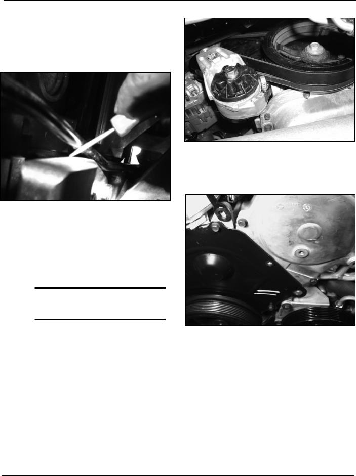
B.Remove the factory alternator pulley cap and using an impact gun with a 17mm allen head socket remove the stock pulley. (See Fig. 6-1.) Install the supplied pulley in its place securing with supplied 17mm nut. Heating the pulley will make the installation easier.
*****NOTE:*****
Do not use the washer supplied with the alternator pulley nut.
C.LOOSELY bolt the alternator mounting bracket to the engine block where the A/C tensioner was bolted (see Fig. 6-2).
Fig. 6-2
Install the supplied drive belt tensioner plate with the spacer (see Fig. 6-3). Align the crank and drive belt pulleys, and tighten the bolts on the drive belt tensioner plate and the alternator mounting plate using a 17mm socket
Fig. 6-3
Fig. 6-1
6-1 |
P/N: 4809629 |
|
©2003 Paxton Automotive |
|
All Rights Reserved, Intl. Copr. Secured |
|
22OCT02 v2.0 PlymProwler(4809629v2.0) |
D.Bolt the alternator support arm to the ear on the alternator. Leave it slightly loose so it can be adjusted. Next, mount the alternator to the bracket. You will have to bend the Oil Dipstick tube up and away from the bracket to make room for the alternator.
(See Fig. 6-4.)
Fig. 6-4
E.Loop the supplied V-belt around the crank pulley, then around the A/C compressor.
F.Remove the two 10mm head nut and bracket, the 15mm head bolt/stud and the 15mm head bolt.
G.To install the A/C tensioner, place the belt over the lower pulley, then under the top adjuster pulley.
*****NOTE:*****
The tensioner pulley will push down on the belt, so make sure the pulley is at the uppermost position. Now bolt the bracket to the engine.
Tighten the bolt by turning the screw count- er-clockwise. When the bolt is sufficiently tight, tighten the lock nut on the front of the A/C tensioner assembly.
H.Complete the alternator wiring. Install the drive belt tensioner. (See Fig. 6-5.)
Fig. 6-5 /
Complete installed Drive Belt Tensioner.
I.Refer to Fig. 6-6. Replace the factory bolts with two 6mm Buttonhead screws from the A/C Tensioner Assembly (p/n 1016032).
Fig. 6-6
P/N: 4809629 |
6-2 |
©2003 Paxton Automotive |
|
All Rights Reserved, Intl. Copr. Secured |
|
22OCT02 v2.0 PlymProwler(4809629v2.0) |
|
Loading...