

Paxton Superchargers RT-10 User Manual

DP/N: 4809646 - v2.0 02/17/06
Owner’s Installation Guide for the
Paxton Automotive
Novi 2000 Supercharger
for the
1992-1996 Dodge Viper RT/10
Paxton Automotive . 1300 Beacon Place . Oxnard CA 93033
805 604-1336 . FAX • 805 604-1337
KIT # 1201810

P/N: 4809646
©2006 Paxton Automotive
All Rights Reserved, Intl. Copr.Secured
17FEB06 v2.0 92-96Viper(4809646v2.0)
ii
FOREWORD
P
roper installation of this supercharger kit requires general
automotive mechanic knowledge and experience. Please
browse through each step of this instruction manual prior to
beginning the installation to determine if you should refer the job
to a professional installer/technician. Please call Paxton
Automotive for installers in your area.
©
2006 PAXTON AUTOMOTIVE
All rights reserved. No part of this publication may be reproduced, transmitted, transcribed,
or translated into another language in any form, by any means without written permission
of Paxton Automotive.

P/N: 4809646
©2006 Paxton Automotive
All Rights Reserved, Intl. Copr.Secured
17FEB06 v2.0 92-96Viper(4809646v2.0)
iii
TABLE OF CONTENTS
FORWORD . . . . . . . . . . . . . . . . . . . . . . . . . . . . . . . . . . . . . . . . . . . . . . . . . . . . . . . . . . . . . . . . . . ii
TABLE OF CONTENTS. . . . . . . . . . . . . . . . . . . . . . . . . . . . . . . . . . . . . . . . . . . . . . . . . . . . . . . . iii
IMPORTANT NOTES . . . . . . . . . . . . . . . . . . . . . . . . . . . . . . . . . . . . . . . . . . . . . . . . . . . . . . . . . iv
RECOMMENDED TOOLS FOR INSTALLATION . . . . . . . . . . . . . . . . . . . . . . . . . . . . . . . . . v
PA RTS LIST (1992-1996 Dodge Viper RT10) . . . . . . . . . . . . . . . . . . . . . . . . . . . . . . . . . . . . . . . . vi
1. PREPATATION/REMOVAL . . . . . . . . . . . . . . . . . . . . . . . . . . . . . . . . . . . . . . . . . . . . . . . . . 1-1
2. OIL FEED. . . . . . . . . . . . . . . . . . . . . . . . . . . . . . . . . . . . . . . . . . . . . . . . . . . . . . . . . . . . . . . 2-1
3. OIL DRAIN. . . . . . . . . . . . . . . . . . . . . . . . . . . . . . . . . . . . . . . . . . . . . . . . . . . . . . . . . . . . . . 3-1
4. CRANK PULLEY INSTALLATION . . . . . . . . . . . . . . . . . . . . . . . . . . . . . . . . . . . . . . . . . . . 4-1
5. REPLACEMENT SHOCK TOWER SUPPORT INSTALLATION . . . . . . . . . . . . . . . . . . . . 5-1
6. SUPERCHARGER MOUNTING BRACKET INSTALLATION . . . . . . . . . . . . . . . . . . . . . . 6-1
7. ALTERNATOR RELOCATION ASSEMBLY . . . . . . . . . . . . . . . . . . . . . . . . . . . . . . . . . . . . 7-1
8. SUPERCHARGER INSTALLATION . . . . . . . . . . . . . . . . . . . . . . . . . . . . . . . . . . . . . . . . . . 8-1
9. CHARGE AIR COOLER INSTALLATION . . . . . . . . . . . . . . . . . . . . . . . . . . . . . . . . . . . . . 9-1
10. AIR INLET DUCT INSTALLATION . . . . . . . . . . . . . . . . . . . . . . . . . . . . . . . . . . . . . . . . . . 10-1
11. TIMING CONTROLLER INSTALLATION . . . . . . . . . . . . . . . . . . . . . . . . . . . . . . . . . . . . . 11-1
13. FUEL INJECTOR REPLACEMENT . . . . . . . . . . . . . . . . . . . . . . . . . . . . . . . . . . . . . . . . . . 13-1
14. FINAL CHECK . . . . . . . . . . . . . . . . . . . . . . . . . . . . . . . . . . . . . . . . . . . . . . . . . . . . . . . . . . 14-1

P/N: 4809646
©2006 Paxton Automotive
All Rights Reserved, Intl. Copr.Secured
17FEB06 v2.0 92-96Viper(4809646v2.0)
iv
T
his product is protected by state common law, copyright and/or patent. All
legal rights therein are reserved. The design, layout, dimensions, geome-
try and engineering features shown in this product are the exclusive property of Paxton Automotive. This product may not be copied or duplicated in
whole or part, abstractly or fundamentally, intentionally or fortuitously, nor
shall any design, dimension, or other information be incorporated into any
product or apparatus without prior written consent of Paxton Automotive.
This supercharger kit is designed to work on stock vehicles. Vehicles with modifications may not be compatible with this kit as delivered and should be tested
with a wide band oxygen sensor and fuel pressure gauge to determine if the
air/fuel ratio is safe. Detonation will quickly damage an engine.
1992-1996 Dodge Viper
IMPORTANT NOTES
When driving the vehicle on non-public roads (off-road applications such as
racing/high rpm) it it recommended that the spark plugs be gapped down to
.032".

P/N: 4809646
©2006 Paxton Automotive
All Rights Reserved, Intl. Copr.Secured
17FEB06 v2.0 92-96Viper(4809646v2.0)
v
B
efore beginning this installation, please
read through this entire instruction book-
let and the Street Supercharger System
Owner's Manual which includes the Automotive
Limited Warranties Program and the Warranty
Registration form.
Paxton supercharger systems are performance
improving devices. In most cases, increases in
torque of 30-35% and horsepower of 35-45% can
be expected with the boost levels specified by
Paxton Automotive. This product is intended for
use on healthy, well maintained engines.
Installation on a worn-out or damaged engine is
not recommended and may result in failure of the
engine as well as the supercharger. Paxton
Automotive is not responsible for engine damage.
Installation on new vehicles will not harm or
adversely affect the break-in period so long as factory break-in procedures are followed.
For best performance and continued durability,
please take note of the following key points:
1. Use only premium grade fuel 91 octane or
higher (R+M/2).
2. The engine must have stock compression
ratio.
3. If the engine has been modified in any way,
check with Paxton prior to using this product.
4. Always listen for any sign of detonation
(pinging) and discontinue hard use (no boost)
until problem is resolved.
5. Perform an oil and filter change upon com-
pletion of this installation and prior to test
driving your vehicle. Thereafter, always use a
high grade SF rated engine oil or a high quality synthetic, and change the oil and filter
every 3,000 miles or less. Never attempt to
extend the oil change interval beyond
3,000 miles, regardless of oil manufacturer's claims as potential damage to the
supercharger may result.
6. Before beginning installation, replace all
spark plugs that are older than 1 year or
10,000 miles with original heat range plugs
as specified by the manufacturer and reset
timing to factory specifications (follow the
procedures indicated within the factory repair
manual and/or as indicated on the factory
underhood emissions tag). Do not use plat-
1. Factory Repair Manual
2. 3/8" Socket and Drive Set: SAE & Metric
3. 1/2" Socket and Drive Set: SAE & Metric
4. 3/8" NPT Tap and Handle
5. Adjustable Wrench
6. Combination Wrench Set
7. Center Punch
8. Springlock 3/8" and 5/8”Fuel Fitting
Disconnect Tool
9. 10 Quarts SH/CF Rated Quality Engine Oil
10. Oil Filter and Wrench
11. Flat #2 Screwdriver
12. Phillips #2 Screwdriver
13. Heavy Grease
14. Silicone Sealer
15. Drill Motor / Pneumatic Right Angle
16. 1/8", 13/32", 5/16" Drill Bits
17. Stepless Clamp Pliers
18. 3/16" Allen Wrench
19. Wire Strippers and Crimpers
20. Utility Knife
21. Ø1-1/8" Hole Saw
22. Pliers
If your vehicle has in excess of 10,000 miles
since its last spark plug change, then you will
also need:
24. Spark Plug Socket
25. NEW Spark Plugs
1992-1996 Dodge Viper
inum spark plugs unless they are original
equipment. Change spark plugs at least
every 15,000 miles and spark plug wires at
least every 50,000 miles.
RECOMMENDED TOOLS
FOR INSTALLATION

P/N: 4809646
©2006 Paxton Automotive
All Rights Reserved, Intl. Copr.Secured
17FEB06 v2.0 92-96Viper(4809646v2.0)
vi
S U P E R C H A R G E R S
1011830 VIPER SUPERCHARGER ASY 1
4PCW038-375 S/C PLY, 8-GRV 3.75" PAXTON 1
2A048-485 BELT, K080485-GATES 1
4PCV118-011 CRANK PULLEY ASY, VIPER 1
4PCV016-011 PULLEY, VIPER 7-GRV 1
4PCV018-011 PULLEY, VIPER 8-GRV 1
4CV110-010 FIXTURE w/GUIDE, DOWEL PIN 1
7A312-100 5/15-18 x 1" HXCS GR5P 6
7A312-101 5/16-18 x 1" SOC 6
7K312-001 5/16"AN WASHER 12
7T100-120 DRILL BIT, #31, Ø.120", HSS 1
7T110-125 REAMER, Ø.1247", HSS 1
7U250-023 DOWEL PIN 1/8" x 1.25" 2
4PCV110-260 ALTERNATOR RLCT ASY, G1 VIPER 1
2A017-101-121 SPACER, FORD ALT. SBF CARB 3
2A017-102-900 SPACER, .900" G1 VIPER IDLER 1
2A017-102-740 SPACER, .740"L, C5 ALT. PLATE 3
2A017-875-02 SPACER, .875"OD x 1.565 LONG 2
2A017-875-04 SPACER, .875"OD x 3.457 LONG 1
4HS017-021 SPACER, S/C BOSS S2000 2
4PCV010-260 PLATE 1 PS ALT, RT10 1
4PCV010-270 PLATE 2 PS ALT, RT10 1
4PCV010-280 PLATE 3 PS ALT, RT10 1
4PCV010-291 PLATE DS ALT, '92-'96 RT10 1
7A375-175 3/8-16 x 1-3/4" HXHD GR5 PLT 1
7A375-225 3/8-16 x 2-1/4" HXHD G8 1
7A375-276 3/8-16 x 2-3/4" HXHD ZINC 2
7A375-350 3/8-16 x 3-1/2" HXHD 2
7A375-451 3/8-16 x 4.50" HXHD GR5 ZINC 1
7A375-475 3/8-16 x 4.75" HXHD GR8 PLTD 1
7C080-035 M8 x 1.25" x 35 BLT CL8.8 1
7J312-000 5/16" FLAT WASHER-SAE 1
7J375-044 3/8"SAE WASHER, PLTD 8
4PCV111-023 MTG BRKT ASY, VIPER RT10 1
4PCV011-023 MTG BRKT, VIPER, MACH 1
4PCV010-044 PLATE, VIPER S/C MTG 1
2A017-101-400 SPACER, SBF MOUNTING PLATE 2
7A375-575 3/8-16 x5-3/4" HXCS 2
7A375-126 3/8-16 x 1.25" HXHD 5
7A375-175 3/8-16 x 1-3/4" HXHD 2
7J375-044 3/8" SAE WASHER, PLTD 12
4FA016-170 IDLER PULLEY, 8-RIB SMOOTH 1
7A375-224 3/8-16 x 2.25" GR5 HX 1
4GF017-011 SPACER, IDLER 3
4PCV011-052 SPRING TENSIONER 1
7C010-035 M10-1.5 x 35 HXCS 1
4PCV210-220 BRACE ASY, VIPER SHOCK 1
4PCV110-220 ASY, VIPER BRACE, DRIVER RT10 1
4PCV110-230 ASY, VIPER BRACE, PSGR RT10 1
4PCV110-180 ASY, VIPER BRACE, XBAR 1
7A437-150 7/16-14 x 1-1/2" G8 2
7B437-001 ROD END, RH, 7/16" 1
7B437-002 ROD END, LH, 7/16" 1
7C010-025 M10-1.5" x 25mm HXCSP 4
7F437-000 7/16-14 HEX NYLOCK NUT 2
7F438-001 7/16-20 JAM NUT, PLTD 1
7F438-002 LH 7/16-20 HEX THIN NUT, ZINC 1
7GL10-150 10mm x 1.5" NUT NYLOCK 4
7J010-002 10mm WASHER, ZINC PLTD 10
7K437-001 7/16" AN WASHER 6
1992-1996 Dodge Viper RT10
Part No. 1201830
IMPORTANT: Before beginning installation, verify that all parts are included in the kit. Report any short-
ages or damaged parts immediately.
PAR
T NO. DESCRIPTION QTY PART NO. DESCRIPTION QTY
PARTS LIST
4PCV130-028 OIL FEED LINE ASY, VIPER 1
7P125-004 1/8"NPT 90° x -4 JIC FTG 2
7P125-034 1/8"NPT x 1/8"NPT STRT T 1
7U100-055 TIE-WRAP, 6" NYLON 2
7U250-220 OIL FEED HOSE, 22" -4 STRT 1
4PCV130-036 OIL DRAIN LINE ASY, VIPER 1
7P375-017 3/8"NPT x 1/2" BEADED 1
7R001-008 #8 STNLS HOSE CLAMP 2
7T560-001 CUTTER, 9/16" ROTABROACH 1
7T560-002 ARBOR, ROTABROACH 1
7U030-036 1/2" OIL-DRAIN HOSE 1.75'
7U100-066 TIE-WRAP, 11" NYLON 2
4PCV112-040 AIR INTAKE ASY, VIPER RT10 1
4PCV012-040 INLET DUCT, VIPER SC RT10 1
7C010-077 10-24 x 3/4" BHCS 12
7R002-064 #64 GOLDSEAL HOSE CLAMP 1
7R002-104 #104 HOSE CLAMP 1
7PS400-650 INLET SLEEVE, VIPER RT10 1
7P625-091 5/8" x 5/8" x 90° BARB ELBOW 1
7U033-000 5/8" FUEL/PCV HOSE .75'
7U100-050 GROMMET 5/8"ID x 7/8" HOLE 1
8H017-021 AIR FILTER RET. RT10 1
8H040-230 AIR FILTER, 4.75" x 15, RT10 1
5A001-074 TIMING CONTROL BOX, VIPER '96-'99 1
5A001-070 TIMING CONTROL BOX, VIPER 1
5W001-017 3/8" RING TERMINAL, 12GA 1
7U375-001 VELCRO-HOOK, 1" BLACK .22YD
7U375-002 VELCRO-LATCH, 1" BLACK .22YD
5W014-010 14GA STRD WIRE, RED 8'
4PCV101-003 FUEL PUMP ASY, VIPER 1
5W001-005 3/8" PLASTIC WIRE LOOM 6'
5W001-011 16-14GA RING TERMINAL, .26" HOLE 2
5W014-030 14GA STRD WIRE, BLACK .75'
7E010-075 #12 x 3/4" SHT METAL SCREW H 4
7P312-005 5/16" FEMALE FUEL CONCT 1
7P312-007 FUEL FITTING, MALE 1
7P312-017 5/16" HOSE BARB TO PBURG 2
7P312-082 5/16" TEE HOSE BARB 4
7R003-027 ADEL CLAMP, 1-11/16" 4
7R004-001 STEPLESS CLAMP, 15.7-70 22
7U031-018 5/16" FUEL HOSE, HI-PRESSURE 8'
7U100-044 TIE-WRAP, 4" NYLON 10
7U100-055 TIE-WRAP, 6" NYLON 5
8F001-068 155 INLINE FUEL PUMP 2
4PCV238-108 FMU ASY, VIPER 1
7P125-025 1/8"NPT x 5/32" HOSE 90° 1
7P125-031 1.8"NPT 90° 5/16" BARB 1
7P125-032 1/8"NPT - STR, 5/16" BARB 1
7P156-082 5/32" TEE 2
7U030-046 5/32" VACUUM LINE 9
6Z050-191 FMU WASHER 8:1 1
6Z070-030 FMU 8:1 RING SPACER 1
4PCV145-040 POWER STEERING HOSE ASY 1
7U030-028 -6 HI-PRESS PWR STR HOSE 1
7P375-216 -6 JIC x M16 x 1.5" BUMP FTG 1
7P375-218 -6 JIC x M18 x 1.5" BUMP FTG 1
7U100-055 TIE-WRAP, 6" NYLON 5
7U100-045 O-RING, .301" 2

P/N: 4809646
©2006 Paxton Automotive
All Rights Reserved, Intl. Copr.Secured
17FEB06 v2.0 92-96Viper(4809646v2.0)
vii
8PN201-020 DISCHARGE ASY, VIPER 1
8PN101-020 CAC ASY, VIPER, AIR/WATER 1
5W001-005 3/8" PLASTIC WIRE LOOM 1.6'
7PS263-090 2-5/8" 90° ELBOW 2
7PS300-300 SLEEVE, BLACK, Ø3.00" x 3.00" 1
7R002-040 #40 STAINLESS HOSE CLAMP 4
7R002-048 #48 GOLDSEAL HOSE CLAMP 2
7U030-046 5/32" VACUUM LINE 3.5'
7U038-012 HOSE, Ø3/4", 90°, 4" x 12" 1
7P375-075 3/4" HOSE UNION 1
7R007-001 NYLON CLAMP 1-1/8" 2
7P500-026 1/2"NPT - 3/4" BARB 90° 1
8D204-010 BYPASS VALVE-BLACK 1
8H040-175 FILTER, 1-3/4"ID, MFRB 1
8PN104-030 SUPPORT COMPONENTS, VIPER RT10 1
7A250-051 1/4-20 x .5" HHCS 2
7A250-074 1/4-20 x 3/4" HXHD PLT 5
7A312-075 5/16-18 x 3/4" HXCS GR5 ZINC 1
7F250-021 1/4-20 NYLOCK NUT ZINC PLT 1
7F312-017 5/16-18 NYLOCK NUT 1
7J250-001 1/4"SAE WASHER, PLTD 8
7K312-001 5/16"AN WASHER, PLATED 2
7U038-150 HOSE 3/4" x 150 MOLDED 1
8N010-100 MTG TAB, RT10 SURGE TANK 1
8N010-120 SUPPORT, RT10 WATER COOLER 2
7F250-021 1/4-20 NUT PLATE 4
7U100-055 TIE-WRAP, 6" NYLON 10
8N055-050 PLASTIC CAP, SURGE TANK 1
8N056-060 SURGE TANK, PLASTIC 1
8PN010-140 SUPPORT, VIPER WATER COOLER 2
7P500-026 1/2"NPT, 3/4" BARB, 90° 1
8PN105-020 WATER TANK MTG ASY, VIPER 1
7A250-050 1/4-20 x 1/2" SHCS ZINC PLTD 2
7J250-001 1/4"SAE WASHER, PLTD 1
7P375-075 3/4" HOSE UNION 2
7P500-026 1/2"NPT - 3/4" BARB 90° 5
7P500-078 1/2"NPT x 3/4" HOSE FITTING 3
7R007-001 NYLON CLAMP 1-1/8" 14
7U038-000 3/4" HEATER HOSE 18
7U038-012 HOSE, Ø3/4" 90°, 4" x 12" 2
8N055-030 TANK, LT1 AFTERCOOLER 1
8N006-010 WATER COOLER 1
S U P E R C H A R G E R S
8PN107-020 WATER PUMP ASY, VIPER 1
5W001-005 3/8" PLASTIC WIRE LOOM 12'
5W001-009 16-14GA MALE SLIDE INSUL 1
5W001-010 16-14GA FEMALE SLIDE INSUL 3
5W001-011 16-14GA EYELET .25" HOLE 2
5W001-013 14-16AWG, SOLDERLESS CONNECTOR 2
5W001-014 FUSE HOLDER, 10GA WIRE 1
5W001-015 FUSE, BLADE TYPE 20AMP 1
5W001-016 RELAY, BOSCH 1
5W001-017 3/8" RING TERMINAL, 12GA 1
5W001-040 12-10GA FEMALE SLIDE INSUL 1
5W014-010 14GA STRD WIRE, RED, UL101 11'
5W014-030 14GA STRD WIRE, BLACK 14'
5W016-010 WIRE, STRND, 16AWG, YELLOW 2'
7A250-074 1/4-20 x 3/4" HXHD PLT 1
7F250-021 1/4-20 NYLOCK NUT ZINC, PLTD 1
7J250-001 1/4"SAE WASHER, PLTD 2
7R003-027 ADEL CLAMP, 1-11/16" 1
7U100-044 TIE-WRAP, 4" NYLON 8
8F001-402 PUMP, WATER, PIERBURG 1
8F060-270 FUEL INJECTOR, GEN2 STK 10
1992-1996 Dodge Viper RT10
Part No. 1201830
IMPORTANT: Before beginning installation, verify that all parts are included in the kit. Report any short-
ages or damaged parts immediately.
PAR
T NO. DESCRIPTION QTY PART NO. DESCRIPTION QTY
PARTS LIST cont’d
8PN301-010 POWER COOLER ASY, VIPER 1

P/N: 4809646
©2006 Paxton Automotive
All Rights Reserved, Intl. Copr.Secured
17FEB06 v2.0 92-96Viper(4809646v2.0)
viii
This Page Left Intentionally Blank.

1-1
P/N: 4809646
©2006 Paxton Automotive
All Rights Reserved, Intl. Copr.Secured
17FEB06 v2.0 92-96Viper(4809646v2.0)
Section 1
COMPONENT REMOVAL
A. Disconnect the Idle Air Control (IAC) motor
hose and the valve cover breather hose from
the air box (air filter housing).
B. Remove all of the inlet ducting up to but not
including the throttle bodies. Remove the
two air box mounting studs from the core
support.
C. Remove the air temperature sensor from the
air box and set aside.
D. Jack the front of the vehicle up and support
with a jack stand under each frame rail.
E. Drain the engine coolant sufficiently to
remove the upper radiator hose.
F. Remove the two screws securing the power
steering cooler to the shock tower brace.
Jack the front of the vehicle up by placing a
jack under the front cross member.
G. Remove the five screws holding the shock
tower brace and remove the brace.
H. Remove the accessory drive belt.
I. Loosen the nut on the high pressure power
steering line where it enters the power steering pump.
J. Remove the three screws securing the power
steering pump to the bracket and set aside
for later use. Remove the three screws
securing the bracket to the head and remove
the bracket.
K. Remove the six 5/16" screws securing the
crank pulley to the harmonic damper and
remove the crank pulley.
L. Remove the front fascia. Close the rear of
the hood to provide access under the front of
the hood. Start by removing the mounting
screws from the bottom of the vehicle and in
the front of each wheel well. Remove the
plastic push connectors from underneath the
leading edge of the hood and from the top of
the radiator air inlet opening. Unplug the fog
and turn signal lights on each side of the
vehicle by reaching behind the front fascia.
Remove the plastic push connector securing
the front fascia to the bumper in front of and
below each headlight. Carefully remove and
set aside the front fascia.
***NOTE***
Carefully note where any alignment shims are located
and replace in the same location when the front fascia
is re-installed.
1. PREPARATION/REMOVAL

1-2
P/N: 4809646
©2006 Paxton Automotive
All Rights Reserved, Intl. Copr.Secured
17FEB06 v2.0 92-96Viper(4809646v2.0)
This Page Left Intentionally Blank.
2-1
P/N: 4809646
©2006 Paxton Automotive
All Rights Reserved, Intl. Copr.Secured
17FEB06 v2.0 92-96Viper(4809646v2.0)
Section 2
OIL FEED
A. Remove the oil pressure sender from the
front passenger side of the engine directly
above the oil filter.
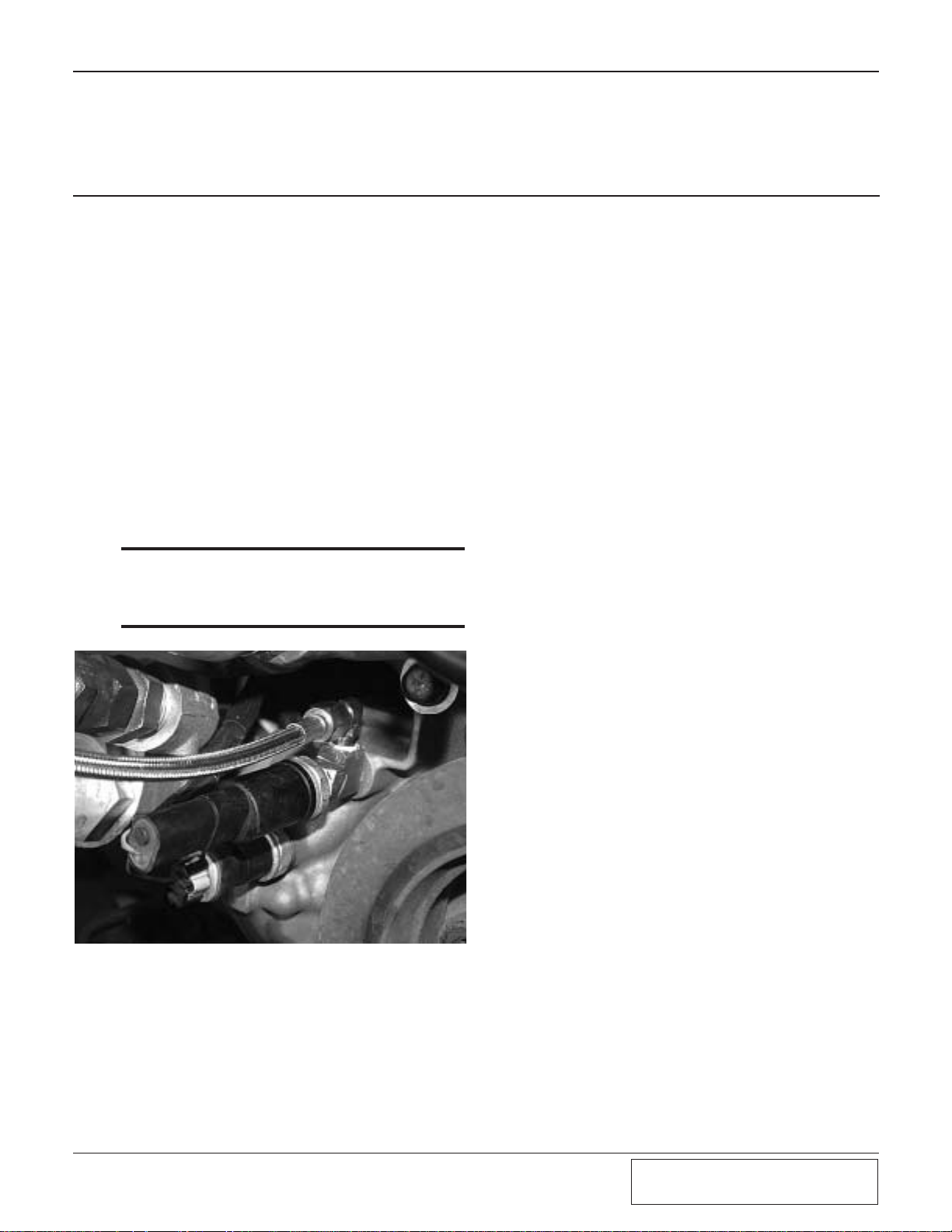
B. Install the 1/8"NPT TEE in the oil sender
hole. Leave the TEE pointed up. Install the
1/8"NPT x -4 90° fitting in the top of the
TEE. Install the oil pressure sender in the
front hole in the TEE and re-attach the electrical plug. (See Fig. 2-a.)
C. Temporarily cover one end of the oil feed
line and protect it from debris until connecting it to the supercharger.
D. Connect the open end of the oil feed line to
the -4 fitting. Use tie-wraps to secure the
line and protect it from kinking, abrasion
and high heat areas.
***IMPORTANT***
Use clean engine oil on the pipe threads. Teflon tape
and sealant is NOT recommended as it might loosen
and cause blockage of the small oil feed orifice resulting in supercharger failure.
2. OIL FEED
Fig. 2-a

2-2
P/N: 4809646
©2006 Paxton Automotive
All Rights Reserved, Intl. Copr.Secured
17FEB06 v2.0 92-96Viper(4809646v2.0)
This Page Left Intentionally Blank.
Section 3
OIL DRAIN
3-1
P/N: 4809646
©2006 Paxton Automotive
All Rights Reserved, Intl. Copr.Secured
17FEB06 v2.0 92-96Viper(4809646v2.0)
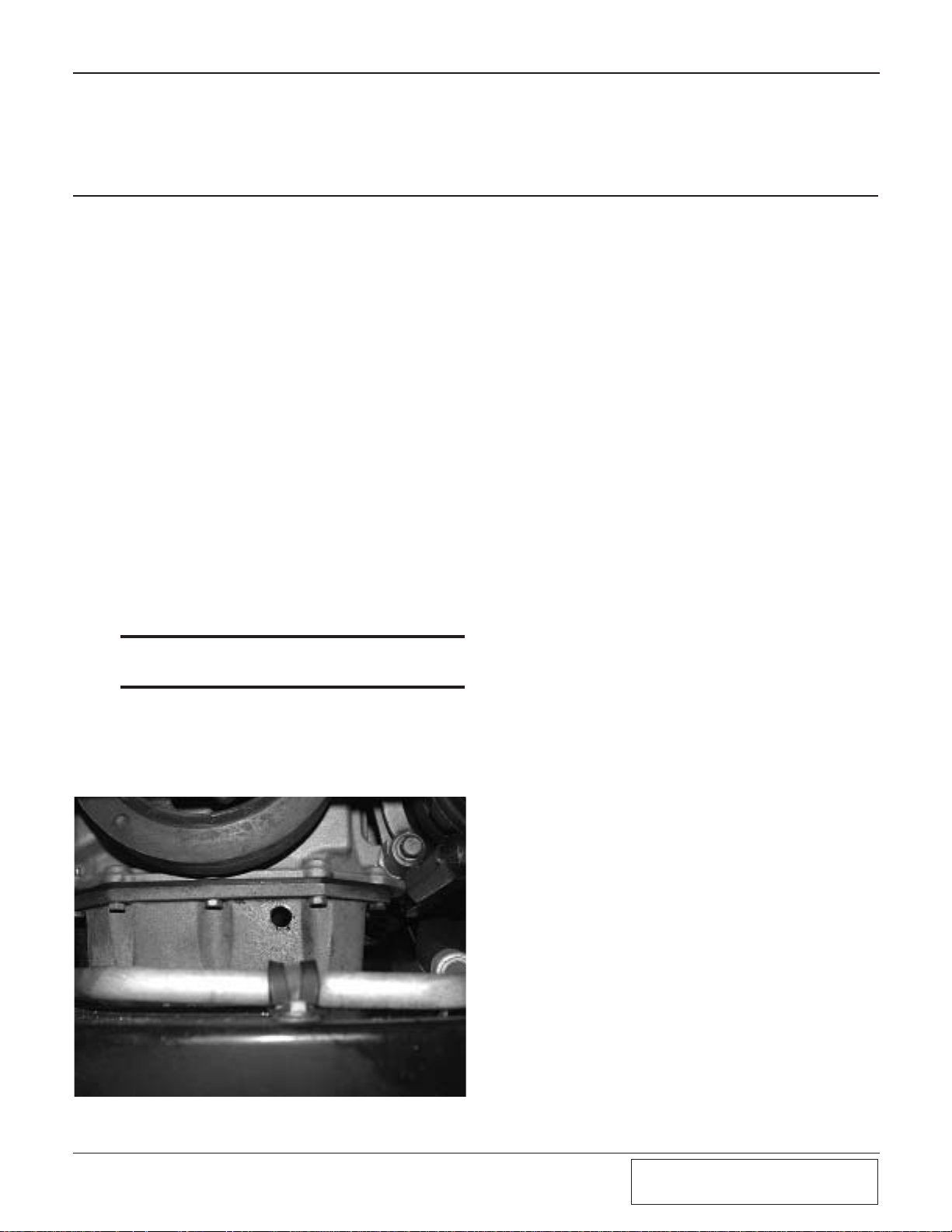
A. To provide an oil drain for the supercharger,
it is necessary to make a hole in the front of
the oil pan.
B. Remove the oil dipstick retaining screw
from the passenger’s side valve cover bracket.
C. Drain the engine oil.
D. Remove the oil pan.
E. The hole should be centered .5" from the
bottom of the oil pan lip as shown. Use a
center punch to mark the hole location. Use
the supplied 9/16" rota-broach to drill the
hole.
F. Tap the hole with a 3/8"NPT pipe tap.
G. Thoroughly clean the threaded area and the
inside of the oil pan. Apply a small amount
of sealer to the new threads. Apply more
sealer to the supplied 3/8"NPT x 1/2" hose
barb fitting and secure in the hole. Make
sure a seal is formed all around the fitting.
***NOTE***
Clean and inspect the oil pan gasket. If it is in good
condition it can be used again.
H. Re-install the oil pan. Torque the fasteners to
95 in-lbs (11 N-m).
I. Install a new oil filter and refill the engine
with fresh oil.
Fig. 3-a
3. OIL DRAIN
 Loading...