

DP/N: 4809622a v2.0 09/07/06
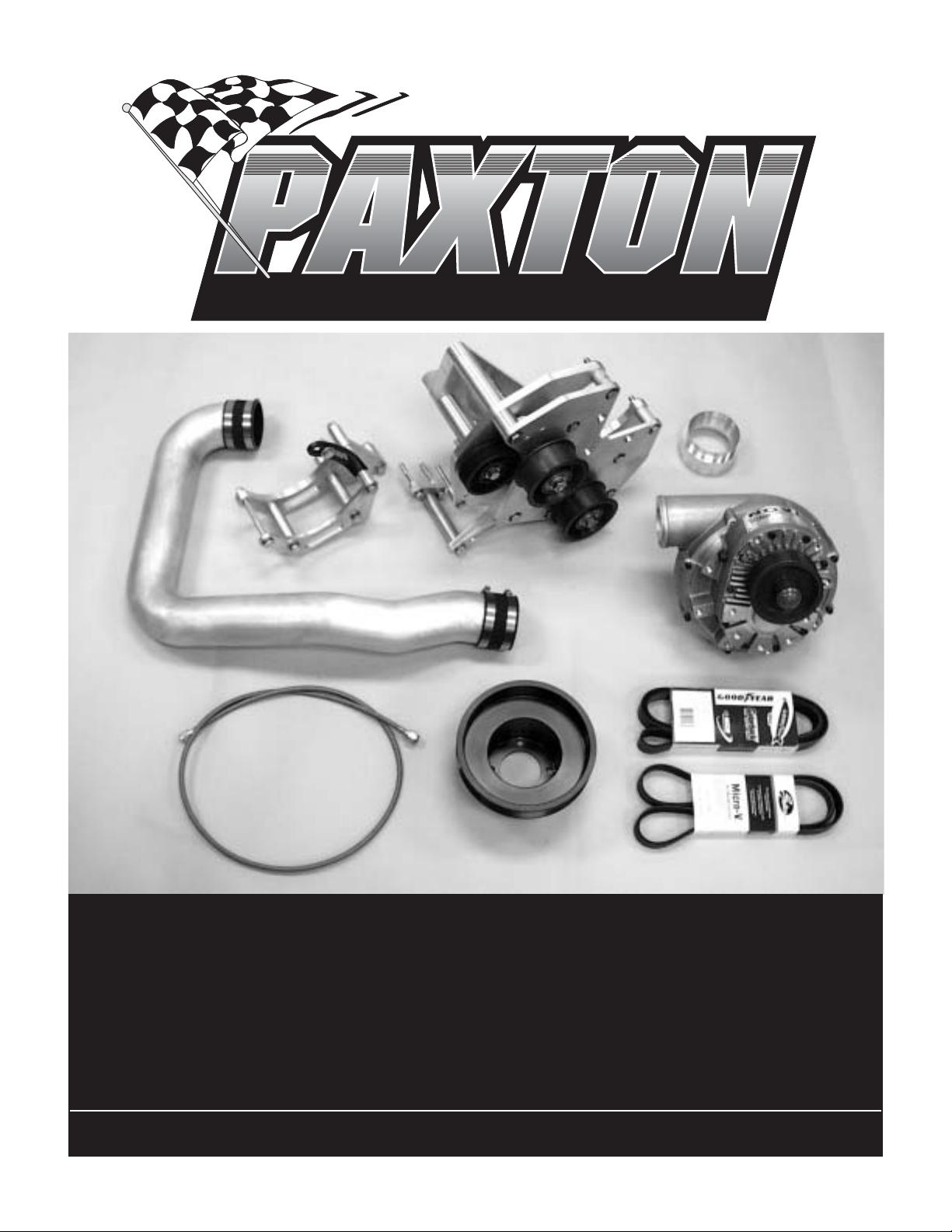
Kit # 1001824
S U P E R C H A R G E R S
Installation Manual for
Paxton Automotive
NOVI 2000
for the
Mustang 5.0L and 5.8L
Renegade Race Class
Paxton Automotive Corporation .1300 Beacon Place .Oxnard, CA 93033
(805) 604-1336 .FAX (805)604-1337

P/N: 4809622a
©2006 Paxton Automotive
All Rights Reserved, Intl. Copr. Secured
07SEP06 v2.0 MusRenegade(4809622a v2.0)
ii
© 2006 PAXTON AUTOMOTIVE
All rights reserved. No part of this publication may be reproduced, transmitted, transcrived, or translated into
another language in any form, by any means without written permission of Paxton Automotive.
FOREWORD
C
ongratulations! You have purchased the finest complete race-ready
supercharger kit available today. The centerpiece of this kit is the
High Efficiency PAXTON NOVI 2000 Race Supercharger, a
mechanically driven centrifugal blower.
This kit comes with all the parts you will need to install the supercharger.
Paxton Automotive assumes that you are an experienced automotive
mechanic, and have a stripped down Mustang 5.0 or 5.8 engine.
For the quickest installation time, we suggest that you read this manual
throughly before beginning. Make sure that you understand the process,
have identified the areas of the car that you will be working on, and have
the tools that you will need on hand. We estimate installation time at less
than 8 hours, not including tune-up. Once again we recommend reading
the manual before beginning the installation. We are available for tech support at 805 647-3796, Monday through Friday, 8:00 AM to 4:30 PM. PST.
After reading the manual, verify that all major assembly groups are present
in the main kit box. As you remove a box or bag, note the identification
label and compare it to the parts list.
PAXTON AUTOMOTIVE makes every effort to insure
that all parts are included in the box. If you discover that
you are missing any part, or that a part was damaged in
shipping, call PAXTON immediately. DO NOT begin
installation if a part is missing. Failure to contact PAXTON
prior to beginning installation will result in a charge for the
missing part.

P/N: 4809622a
©2006 Paxton Automotive
All Rights Reserved, Intl. Copr. Secured
07SEP06 v2.0 MusRenegade(4809622a v2.0)
iii
TABLE OF CONTENTS
FOREWORD . . . . . . . . . . . . . . . . . . . . . . . . . . . . . . . . . . . . . . . . . . . . . . . . . . . . . . . . . . . . .ii
TABLE OF CONTENTS . . . . . . . . . . . . . . . . . . . . . . . . . . . . . . . . . . . . . . . . . . . . . . . . . . .iii
IMPORTANT NOTES . . . . . . . . . . . . . . . . . . . . . . . . . . . . . . . . . . . . . . . . . . . . . . . . . . . . .iv
1. RENEGADE RACE KIT INSTALLATION . . . . . . . . . . . . . . . . . . . . . . . . . . . .1-1
1.1 SUPERCHARGER MOUNTING BRACKET INSTALLATION . . . . . . . . . . . . .1-1
2. MOUNTING PLATE INSTALLATION . . . . . . . . . . . . . . . . . . . . . . . . . . . . . . .2-1
2.1 INSTALL THE S/C MOUNTING PLATE . . . . . . . . . . . . . . . . . . . . . . . . . . . . . .2-1
2.2 PLASTIC IDLER INSTALLATION . . . . . . . . . . . . . . . . . . . . . . . . . . . . . . . . . . .2-1
3. ALTERNATOR MOUNTING BRACKET INSTALLATION . . . . . . . . . . . . . . .3-1
3.1 ALTERNATOR RELOCATION . . . . . . . . . . . . . . . . . . . . . . . . . . . . . . . . . . . . . .3-1
4. AIR INLET / DISCHARGE TUBE INSTALLATION . . . . . . . . . . . . . . . . . . . . .4-1
4.1 INSTALL THE DISCHARGE TUBE . . . . . . . . . . . . . . . . . . . . . . . . . . . . . . . . . .4-1
5. CRANK PULLEY INSTALLATION . . . . . . . . . . . . . . . . . . . . . . . . . . . . . . . . .5-1
5.1 INSTALL THE CRANK PULLEY . . . . . . . . . . . . . . . . . . . . . . . . . . . . . . . . . . . .5-1
6. A FINAL WORD . . . . . . . . . . . . . . . . . . . . . . . . . . . . . . . . . . . . . . . . . . . . . . . .6-1
APPENDIX . . . . . . . . . . . . . . . . . . . . . . . . . . . . . . . . . . . . . . . . . . . . . . . . . . . . . . .A-1
B. 1016039 ASY, MOUNTING BRACKET . . . . . . . . . . . . . . . . . . . . . . . . .A-2
C. 1016106 ASY, NOVI 2000 SUPERCHARGER . . . . . . . . . . . . . . . . . . . .A-3
D. 1015612 ASY, CRANK PULLEY . . . . . . . . . . . . . . . . . . . . . . . . . . . . . .A-4
E. 1016040 ASY, ALTERNATOR RELOCATION BRACKET . . . . . . . . . . .A-5
F. 1019329 ASY, OIL SUPPLY HOSE . . . . . . . . . . . . . . . . . . . . . . . . . . . . .A-6
G. 1016009 ASY, DISCHARGE TUBE . . . . . . . . . . . . . . . . . . . . . . . . . . . .A-7

P/N: 4809622a
©2006 Paxton Automotive
All Rights Reserved, Intl. Copr. Secured
07SEP06 v2.0 MusRenegade(4809622a v2.0)
iv
Never rely solely on a floor jack when
working underneath a vehicle. Always
use jack stands that are rated for the
weight of your vehicle, use them at the
recommended lift points, and place your
vehicle in ‘PARK’ or ‘FIRST’ gear with the
parking brake set.
Always use eye protection when using power
tools, such as drills, saws, and grinders, or
when working underneath a vehicle.
Never smoke, use an open flame, or have spark
producing items around gasoline or flammable
objects. Always have a fire extinguisher that
is rated for chemical and electrical fires handy
when working on motor vehicles. Also, make sure
that the extinguisher is fully charged.
Operate engines only in a well ventilated area. Carbon
Monoxide, gasoline, and solvent vapors
are colorless and sometimes odorless, and
may asphyxiate and explode without
warning.
Always disconnect the battery from
your engine before doing work on the electrical
or fuel systems, or doing underdash work.
The chemicals used in the vehicle systems,
such as oils and coolants, are poisonous. Clean
up any spills immediately, and dispose of
waste materials properly. Pets, wild animals, and
children may die if they ingest the liquid.
PAXTON Automotive thanks you for your purchase.We welcome your com-
ments and suggestions to help us improve our products.
We suggest that the engine compartment be
cleaned before the installation. You can clean the
engine with a pressure washer that is found at selfserve car washes. Use a safe-for-aluminum cleaner/degreaser, and cover the distributor and any
electronics with a plastic bag to prevent water from
entering.
You are endoubtedly eager to get started, but
please take a little more time to insure that your
safely is not in jeopardy. A moments’s lack of
attention may cause a serious injury to you, or to
someone else who happens to be standing around.
By following list is not meant to be a comprehensive list, bu rather it is meant to make you aware of
some of the risks, and encourage you to take a
safety minded approach to your work area.
IMPORTANT NOTES

P/N: 4809622a
©2006 Paxton Automotive
All Rights Reserved, Intl. Copr. Secured
07SEP06 v2.0 MusRenegade(4809622a v2.0)
1-1
P/N 33 ATTACHES HERE
7-Bolt Points for the S/C Bracket
X
X
X
X
X
X
X
Before beginning the installation of your supercharger, the engine should have all of its accessory drive components removed.
1.1 SUPERCHARGER MOUNTING
BRACKET INSTALLATION
A. If you have not already done so, remove the
alternator.
1. Disconnect the battery
2. Relieve tension on the drive belt
3. Remove the belt
4. Remove the alternator
5. Remove the water pump pulley
B
. Install mounting bracket. (See Appendix “B”,
mounting bracket assembly.)
*** NOTE ***
We suggest that you assemble the mounting bracket
in an organized fashion, keeping the parts in order, as
is shown in Appendix “B”. It is especially critical to
keep the proper spacers and washers together with
their bolts. Refer to Appendix “B” for there locations.
*** NOTE ***
Leave out the spacers (items #11, #40, and #41) in
the initial installation of the mounting bracket. After
the complete installation of the bracket, slip the spacers into place. If the spacers do not fit snugly, the
spacers will have to be machined. This is due to the
factory variations of the engine.
Section 1
RENEGADE RACE KIT INSTALLATION
Fig. 1-a
C. Place the triangular spacer (item #12) against
the cylinder head, and attach the back plate
(item #3) to the engine block using the 2.5" x
7/16" screw and washer, (items #33, #34). The
screw passes throught the spacer and into the
cylinder head at the point shown. (See
Fig. 1-a.)
D. Slip the spacers (items #5, #6) into the counter-
bored holes in the back plate.
E. Attach the small triangular bracket (item #8) to
the lower part of the timing cover using bolts
(items #26, #27). (See Fig. 1-a.)

P/N: 4809622a
©2006 Paxton Automotive
All Rights Reserved, Intl. Copr. Secured
07SEP06 v2.0 MusRenegade(4809622a v2.0)
1-2
This Page Left Intentionally Blank

P/N: 4809622a
©2006 Paxton Automotive
All Rights Reserved, Intl. Copr. Secured
07SEP06 v2.0 MusRenegade(4809622a v2.0)
2-1
2.1 INSTALL THE S/C MOUNTING
PLATE
2.2 PLASTIC IDLER INSTALLATION
A. Attach the supercharger mounting plate,
(item #2) to the back plate using the 7-1/2" long
7/16" bolt (item #31). DO NOT fully tighten.
DO NOT install the bolts and spacers that go
into the water pump at this time. (items #40,
#41.)
B. Slide the three 7/16" bolt with washers (item
#32, #35) through the front supercharger sup-
port plate. Slide the spacers onto the bolts, and
loosely attach the bolts to the other brackets.
C. Slide the support arm (item #7) between the
two plates until the single hole at the end of the
support arm lines up with the hole at the center
of the triangular bracket. (Item #8.)
*** NOTE ***
There are two sets of holes in the support arm. This
is to accommodate the diffeent deck heights on the
302 and 351 engines. Secure the support arm using
the two 3/8" bolts (item #22). DO NOT fully tighten.
DO NOT install the spacer (item #11) at this time.
Section 2
MOUNTING PLATE INSTALLATION
C. Go back and tighten all loose bolts. Check the
fit of the remaining spacers (items #11, #40,
#41). They should fit snugly into place. Due to
the factory tolerance, after market heads, water
punps, gasket thicknesses, etc., these spacers
may need to be shortened slightly. Failure to
assure a proper fit for these spacers, either leaving them too long or too short, will cause the
bracket to sit crooked and may cause a thrown
belt. Measure as accurately as possible.
*** NOTE ***
The 351 based engines will use only one bolt and
spacer into the water pump.
D. Install the idler pulleys (item #17, #19), the
supercharger bolts (item #21) and spacers
(item #4).
1. Attach the oil drain (not provided in this
kit) to the supercharger.
2. Attach the oil supply hose (Appendix “F”)
to the NOVI 2000.
3. Install the NOVI 2000 Race Supercharger.
4. Connect the oil supply hose to an oil sup-
ply. This can be located at the oil sender
unit.
A. Install the plastic accessory idler using the
8-3/4" long bolt and washer (items #29, #30)
and the step collar (item #18). DO NOT fully
tighten.
B. Slide the spacer (item #10) between the two
plates so it lines up with the hole that is the second from the bottom, as shown in Appendix
“B”. Slide the bolt (item #36) through both
plates and spacer to hold it in place.
*** NOTE ***
If you are using a pulley combinaztion other than
those supplied by Paxton, you may have to re-position this spacer either up or down, depending on the
pulley diameter. DO NOT install the pulley at tlhis
time.

P/N: 4809622a
©2006 Paxton Automotive
All Rights Reserved, Intl. Copr. Secured
07SEP06 v2.0 MusRenegade(4809622a v2.0)
2-2
This Page Left Intentionally Blank

P/N: 4809622a
©2006 Paxton Automotive
All Rights Reserved, Intl. Copr. Secured
07SEP06 v2.0 MusRenegade(4809622a v2.0)
3-1
3.1 ALTERNATOR RELOCATION
Section 3
ALTERNATOR MOUNTING BRACKET INSTALLATION
*** NOTE ***
The alternator Relocation kit was designed for the
factory '86-'93 style 70 AMP alternator with the stock
pulley. If you are running an underdrive pulley you
will need to acquire a longer belt. This bracket will
not accommodate the larger 140 AMP alternator. For
most racing applications, 70 AMPS is more than
enough to power the multiple fuel pumps, computers,
and ignition systems.
A. Install the alternator Relocation Bracket (See
Fig. 3-a, Appendix “E”), including the water
pump pulley, to the engine block at the points
indicated. (See Fig. 3-b.)
B. Install the alternator.
WATER PUMP
PULLEY LOCATION
Fig. 3-a
Fig. 3-b
ALTERNATOR BRACKET
LOCATIONS

P/N: 4809622a
©2006 Paxton Automotive
All Rights Reserved, Intl. Copr. Secured
07SEP06 v2.0 MusRenegade(4809622a v2.0)
3-2
This Page Left Intentionally Blank

P/N: 4809622a
©2006 Paxton Automotive
All Rights Reserved, Intl. Copr. Secured
07SEP06 v2.0 MusRenegade(4809622a v2.0)
4-1
Section 4
AIR INLET/DISCHARGE TUBE INSTALLATION
4.1 INSTALL THE DISCHARGE TUBE
RENEGADE SLEEVE ATTACHED TO
NOVI 2000 (CUTAWAY)
A. Install the discharge tube to the NOVI 2000
supercharger. (See Appendix “G”.)
B. Attach one 3.00" sleeve to the discharge of the
supercharger with two T-bolt clamps that are
provided. Leave the clamps loose.
C. Install (item #2 4PFA012-071) to the 3.00"
sleeve just installed to the discharge of the S/C.
D. Attach a 3.00" sleeve and clamps to the dis-
charge duct (item #1 4PFA012-051) and attach
duct to item #2 previously installed to the discharge of the S/C.
E. Attach two 3.00" sleeves and clamps to the dis-
charge duct (item #3, 4PFA012-061), and attach
to the previous duct that was installed.
F. Adjust ducts for alignment and tighten clamp
G. To be legal for the Renegade Race Class, install
the Renegade Venturi Sleeve at the inlet of the
supercharger. (See Fig. 4-a.)
Fig. 4-a

P/N: 4809622a
©2006 Paxton Automotive
All Rights Reserved, Intl. Copr. Secured
07SEP06 v2.0 MusRenegade(4809622a v2.0)
4-2
This Page Left Intentionally Blank

P/N: 4809622a
©2006 Paxton Automotive
All Rights Reserved, Intl. Copr. Secured
07SEP06 v2.0 MusRenegade(4809622a v2.0)
5-1
Section 5
CRANK PULLEY INSTALLATION
A. Install the crank pulley. (See Fig. 5.1-a and
Appendix “D”.)
B. Torque all bolts down to factory specs.
C. Install the drive belts. First the alternator belt
(around the 6-groove pulley), then the supercharger drive belt.
D. This completes the installation of the NOVI
2000.
5.1 INSTALL THE CRANK PULLEY
Fig. 5.1-a | Crank Pulley Location

P/N: 4809622a
©2006 Paxton Automotive
All Rights Reserved, Intl. Copr. Secured
07SEP06 v2.0 MusRenegade(4809622a v2.0)
5-2
This Page Left Intentionally Blank

P/N: 4809622a
©2006 Paxton Automotive
All Rights Reserved, Intl. Copr. Secured
07SEP06 v2.0 MusRenegade(4809622a v2.0)
6-1
Fig. 6.1-b
Thank you for purchasing this Paxton supercharger. Please understand that we are constantly improving and upgrading our product,
so there may be pictures in this manual showing parts trhat appear different than the parts
in your kit. This may be due to pictures taken
in pre-production, a change in material, or a
different engine model year for our illustrations. Rest assured that the parts will install in
the same way as described in this manual.
You have purchased the most up-to-date kit
that Paxton is selling at this time.
Section 6
A FINAL WORD

P/N: 4809622a
©2006 Paxton Automotive
All Rights Reserved, Intl. Copr. Secured
07SEP06 v2.0 MusRenegade(4809622a v2.0)
6-2
This Page Left Intentionally Blank

P/N: 4809622a
©2006 Paxton Automotive
All Rights Reserved, Intl. Copr. Secured
07SEP06 v2.0 MusRenegade(4809622a v2.0)
A-1
APPENDIX
Thank you for purchasing this Paxton Supercharger. Please understand
that we are constantly improving and upgrading our product, and so
there may be pictures in this manual showing parts that appear to be
different from the parts in your kit. This may be due to pictures taken in
pre-production, a change in material, or a different engine model year
for our illustrations. Rest assured that the parts will install in the same
fashion as is described in this manual, and that you have purchased the
most up-to-date kit that Paxton is selling at this time.

P/N: 4809622a
©2006 Paxton Automotive
All Rights Reserved, Intl. Copr. Secured
07SEP06 v2.0 MusRenegade(4809622a v2.0)
A-2
B
B. 1016039 ASY, MOUNTING BRACKET
REV.
DESCRIPTION
SCREW, HXHD, .312-18UNC-2A x 2.75"LG, STEEL GR8
WASHER, FLAT, .312"
SCREW, HXHD, .438-14UNC-2A x 8.75"LG, STEEL GR8
WASHER, FLAT, HEAVY, .438"
SCREW, HXHD, .438-14UNC-2A x 7.50"LG, STEEL GR8
SCREW, HXHD, .438-14UNC-2A x 7.00"LG, STEEL GR8
SCREW, HXHD, .438-14UNC-2A x 2.50"LG, STEEL GR8
WASHER, FLAT, .438"
SCREW, HXHD, MODIFIED, .438-14UNC-2A x 7.00"LG, STEEL GR8
SCREW, HXHD, .500-20UNF-2A x 5.00"LG, STEEL GR8
WASHER, FLAT, HEAVY, .500"
NUT, HEX, JAM, .500-20UNF-2B, STEEL GR5
SCREW, HXHD, .312-18UNC-2A x 6.25"LG, STEEL GR8
SPACER, .750"O.D. x .316"I.D. x 1.825"LG
PART NO.
7J312-000
7J438-072
7J438-081
7J500-001
7A312-275
7A437-875
7A437-750
7A437-700
7A437-250
141112151132211
QTY.
272829303132333435363738394041
ITEM NO.
7B500-500
7PA437-700
7F500-020
7A312-625
2A017-752-04
12
5
18
4
SPACER, .750"O.D. x .316"I.D. x .894"LG
2A017-752-02
9
3
5
1300 BEACON PLACE OXNARD, CA 93033
TEL: (805) 604-1336 FAX: (805) 604-1337
RACE KIT, RENEGADE
33
6
41
38
34
40
15
13
14
19
29
37
2
9
4
39
28
34
31
8
10
27
26
28
28
11
7
1
21
DATE
4/19/00
A. PROCTOR
APPROVALS
CAD GENERATED DRAWING,
DO NOT MANUALLY UPDATE
DRAWN
±1/2•
.XXX±.005
.XX± .01
ANGLES: ±1/16
DECIMALS:
FRACTIONS:
UNLESS OTHERWISE SPECIFIED
DIMENSIONS ARE IN INCHES
TOLERANCES ARE:
23
20
35
SHEET 1 OF 1
1016039
DO NOT SCALE DRAWING
ASY, MOUNTING BRACKET RENEGADE
D
1:2
SCALE:
SIZE: DWG. NO.:
5/4/00
5/4/00
5/4/00
GRE
23.8 LBS
B. WYMAN
G. COMPTON
APPR.
ENGINEERING
R&D
WEIGHT
NONE
SEE PARTS LIST
MATERIAL
FINISH
DESCRIPTION
BRKT, FRONT PLATE
ASY, S/C MOUNTING PLATE
BRKT, BACK PLATE
SPACER, .875"O.D. x .386"I.D. x 1.175"LG
SPACER, 1.250"O.D. x .438"I.D. x 3.970"LG
SPACER, SPECIAL CUT, 1.250"O.D. x .438"I.D. x 3.970"LG
SUPPORT ARM
BRKT, TRIANGULAR SUPPORT
SPACER, 1.250"O.D. x .438"I.D. x 1.175"LG
SPACER, 1.500"O.D. x .500"I.D. x 1.175"LG
SPACER, .875"O.D. x .386"I.D. x 3.782"LG
SPACER, TRIANGULAR
BRKT, IDLER ADJUSTING
SCREW, IDLER ADJUSTING
ARBOR, TENSIONER
COLLAR, STEP
ASY, PULLEY IDLER
1016071
PART NO.
4PFP010-054
4PFP010-031
4PFP017-021
4PFP017-031
4PFP010-021
4PFP010-061
4PFP017-011
4PFP017-041
2A017-879-01
1116411131111112211962132
QTY.
123456789
ITEM NO.
4PFP017-091
2A017-879-03
1011121314151617181920212223242526
7PA375-500
7PB500-313
4PFA010-031
1210507
4PFP017-071
COLLAR, STEP
PULLEY, IDLER 6 GRV
WASHER, FLAT, .375"
SCREW, HXHD, .375-16UNC-2A x 2.75"LG, STEEL GR5
SCREW, HXHD, .375-16UNC-2A x 2.00"LG, STEEL GR5
SCREW, HXHD, .375-16UNC-2A x 4.75"LG, STEEL GR8
SCREW, FLHD, SOC, .375-16UNC-2A x .75"LG, STEEL GR8
SCREW, FLHD, SOC, .250-20UNC-2A x .75"LG, STEEL GR5
SCREW, HXHD, .312-18UNC-2A x 3.00"LG, STEEL GR8
7J375-044
7A375-276
7A375-200
7A375-475
7A375-077
7A250-077
4PFP017-081
4PFG016-150
7A312-300
1
A
30
24
24
25
21
32
20
34
8 PLACES
16
37
38
22
21
32
34
16
36
17
37

P/N: 4809622a
©2006 Paxton Automotive
All Rights Reserved, Intl. Copr. Secured
07SEP06 v2.0 MusRenegade(4809622a v2.0)
A-3
F
C. 1016106 ASY, NOVI 2000 SUPERCHARGER
REV.
.62
SHEET 1 OF 1
1016111
S/C ROTATION
DESCRIPTION
GEARCASE ASY, N2K, CW, SAT
FTG, NIPPLE, 3/8"NPT x 5/8" HOSE BARB
FTG, PLUG, 3/8"NPT WITH MAGNET
WASHER, COPPER CRUSH, 3/8"
OIL JET, LONG
SCREW, SCHD, 3/8-16UNC-2A x 1.00"LG.
CAP, SHIPPING, T2
KEY, 1/8"SQ x 1.25"LG.
SPACER, PULLEY, .125"THK.
RET, CUP BLWR PULLEY
PULLEY RETAINER S/C
CAP, TAMPER PROOF
SCREW, HXHD, 3/8-24UNF-2A x 1.00"LG.
VOLUTE, MACH, N2K, STR, CW, EXHONE
CAP, SHIPPING, 3"
CAP, SHIPPING, 4"
NAMPLATE, NOVI 2000
DRIVE SCREW, #4 x .187", GR5
WASHER, ANTI-ROTATION
CLAMP, VOLUTE
1/4-20 x .50" SHCS
CAP, SHIPPING, T5
MATING RING, .090"THK.
SHIM, IMP, .003"THK.
SHIM, IMP, .005"THK.
SHIM, IMP, .010"THK.
MATING RING, .099"THK.
MATING RING, .103"THK.
MATING RING, .112"THK.
MATING RING, .090"THK.
SHIM, IMP, .003"THK.
IMPLR, BAL, NOVI 2K, CCW
17
33 3
1
2
PART NO.
7P375-625
2H238-000
112211121111111114136100000001111
QTY
123456789
ITEM NO.
7J375-024
7P375-016
20
008704
7P375-104
7PP375-090
32 2 4
7
5
4
008718
008706
008719
7U100-075
7B375-110
2H017-125
2H040-021
2H040-011
2H018-061
2H100-035
11121314151617181920212223242526272829303127323334
3 REQD
21
6 REQD
22
2
7U100-021
2H017-021
2H100-045
23
008720
7A250-050
2H060-030
2H100-003
2H100-005
2H100-010
2
2H060-031
2H060-040
2H060-041
2H060-030
2H100-003
2H021-211
2
1300 BEACON PLACE OXNARD, CA 93033
TEL: (805) 604-1336 FAX: (805) 604-1337
NUT, IMP 3/8"LH SL 6PT
PULLEY, S/C 8-GRV 3.75"
DEFAULT
7F375-024
1
98-00 6.9L FORD F-350
DATE
10/14/98
RV
APPROVALS
CAD GENERATED DRAWING,
DO NOT MANUALLY UPDATE
DRAWN
±1/2•
.XXX±.005
.XX± .01
ANGLES: ±1/16
DECIMALS:
FRACTIONS:
UNLESS OTHERWISE SPECIFIED
DIMENSIONS ARE IN INCHES
TOLERANCES ARE:
ASY, S/C NOVI 2000
FORWARD ROTATION, 98-01 6.9L, SATIN
D
SIZE: DWG. NO.:
-----
-----
-----
-----
-----
-----
ENGINEERING
R&D
APPR.
NONE
SEE PARTS LIST
MATERIAL
FINISH
DO NOT SCALE DRAWING
3:4
SCALE:
21.8 LBS
WEIGHT
27 22829
AS REQD
16
AS REQD
3
1
223
33
9
?
19
8
4 REQD
4
6
LONG HUB
AWAY FROM S/C
34
11
12
3
14
13
NOTES: UNLESS OTHERWISE SPECIFIED
1. ALL PARTS TO BE SUITABLY PROTECTED AT ALL TIMES TO PREVENT DAMAGE.
2. SHIM IMPELLER TO .031 WORKING HEIGHT USING ITEMS 25, 26, 27, 28,
29, 30, AND 31 (FLOOR STOCK) AS REQUIRED.
3. TORQUE TO 36 FT-LBS.
4. HEAT TO 200°F TO EASE ASSEMBLY.

P/N: 4809622a
©2006 Paxton Automotive
All Rights Reserved, Intl. Copr. Secured
07SEP06 v2.0 MusRenegade(4809622a v2.0)
A-4
1300 BEACON PLACE OXNARD, CA 93033
D. 1015612 ASY, CRANK PULLEY
TEL: (805) 604-1336 FAX: (805) 604-1337
PULLEY, CRANK
SCREW, SOC HD, .375-16UNC-2A x 1.50"LG., STEEL GR8
WASHER, FLAT, 3/8", STEEL
BELT, 8-GRV MICRO-V 56.0"LG x 28mm WIDE
DATE
4/12/00
7A375-158
7K375-040
2A048-560
4FA018-029
CAD GENERATED DRAWING,
DO NOT MANUALLY UPDATE
AP
APPROVALS
DRAWN
144
123
ITEM NO. QTY. PART NO. DESCRIPTION
1
4
1
A
REV.
1015612
ASY, CRANK PULLEY
5.0 - 5.8L RENEGADE
C
SIZE: DWG. NO.:
4/12/00
4/12/00
4/12/00
GRE
B. WYMAN
G. COMPTON
ENGINEERING
R&D
APPR.
SHEET 1 OF 1
DO NOT SCALE DRAWING
1:1
SCALE:
2.2 LBS
WEIGHT
4 PLACES
3
1
4 PLACES
2
.XXX±.005
±1/2•
.XX± .01
DECIMALS:
FRACTIONS:
UNLESS OTHERWISE SPECIFIED
DIMENSIONS ARE IN INCHES
TOLERANCES ARE:
ANGLES: ±1/16
SEE PARTS LIST
MATERIAL
NONE
FINISH
NOTES: UNLESS OTHERWISE SPECIFIED
1. THIS PART TO BE SHIPPED SEPERATELY.

P/N: 4809622a
©2006 Paxton Automotive
All Rights Reserved, Intl. Copr. Secured
07SEP06 v2.0 MusRenegade(4809622a v2.0)
A-5
A
E. 1016040 ASY, ALTERNATOR RELOCATION BRACKET
REV.
SHEET 1 OF 1
ASY, ALTERNATOR
RACE KIT, RENEGADE
4/10/00
3/27/00
4/10/00
GRE
G. COMPTON
G. COMPTON
DRAWN
ENGINEERING
R&D
SEE PARTS LIST
ANGLES: ±1/16
MATERIAL
1016040
DO NOT SCALE DRAWING
D
1:2
SCALE:
SIZE: DWG. NO.:
4/10/00
3.5 LBS
B. WYMAN
WEIGHT
APPR.
NONE
FINISH
8
1300 BEACON PLACE OXNARD, CA 93033
8
1
7
DESCRIPTION
BRKT, ALTERNATOR REAR
BRKT, ALTERNATOR FRONT
BRKT, ALTERNATOR ADJUSTMENT
SPACER, .875"O.D. x .438"I.D. x .867"LG.
SPACER, .875"O.D. x .438"I.D. x 1.845"LG.
SPACER, .875"O.D. x .386"I.D. x 2.985"LG.
SPACER, 1.000"O.D. x .438"I.D. x 1.970"LG.
SPACER, 1.000"O.D. x .386"I.D. x 1.970"LG.
SCREW, HEX CAP, .375-16UNC-2A x 6.50"LG., STEEL, GR5
SCREW, HEX CAP, .375-16UNC-2A x 3.25"LG., STEEL, GR5
SCREW, HEX CAP, .438-14UNC-2A x 6.50"LG., STEEL, GR5
SCREW, HEX CAP, .375-16UNC-2A x 3.75"LG., STEEL, GR5
WASHER, FLAT, 7/16" x 15/16"O.D. x .06"THK, STEEL, GR5
WASHER, FLAT, 3/8" x 13/16"O.D. x .06"THK, STEEL, GR5
SCREW, HEX CAP, .375-16UNC-2A x 4.50"LG., STEEL, GR5
SCREW, HEX CAP, .375-16UNC-2A x 1.00"LG., STEEL, GR5
NUT, HEX, .375-16UNC-2B, STEEL, GR5
PULLEY, WATER PUMP
14
17
14
6
16
5
3
PART NO.
4PFP015-031
4PFP015-021
4PFP015-011
4PFP017-061
4PFP017-051
2A017-880-01
2A017-880-03
2A017-879-05
1111121211111611111
QTY.
123456789
ITEM NO.
10
6
2
7J438-081
7A375-650
7J375-044
7A375-324
7A437-650
7A375-375
7A375-451
101112131415161718
7F375-016
7A375-100
4PFP016-081
1
TEL: (805) 604-1336 FAX: (805) 604-1337
BELT, 6-GRV, 56.0"LG. x 21mm WIDE
DATE
2A046-560
19
APPROVALS
1
CAD GENERATED DRAWING,
DO NOT MANUALLY UPDATE
±1/2•
.XXX±.005
.XX± .01
DECIMALS:
FRACTIONS:
UNLESS OTHERWISE SPECIFIED
DIMENSIONS ARE IN INCHES
TOLERANCES ARE:
14
4
14
9
13
11
14
15
14
12
NOTES: UNLESS OTHERWISE SPECIFIED
1. SHIP THESE ITEMS LOOSE.

P/N: 4809622a
©2006 Paxton Automotive
All Rights Reserved, Intl. Copr. Secured
07SEP06 v2.0 MusRenegade(4809622a v2.0)
A-6
DESCRIPTION
F. 1019329 ASY, OIL SUPPLY HOSE
HOSE, OIL, AN4 x AN4 x 24.0"LG.
FTG, ELBOW, AN4 x 1/8"NPT
FTG, STREET TEE, 1/4"NPT
FTG, NIPPLE, AN4 x 1/4"NPT
C
REV.
SHEET 1 OF 1
1019329
1300 BEACON PLACE OXNARD, CA 93033
TEL: (805) 604-1336 FAX: (805) 604-1337
ASY, OIL SUPPLY
RACE KIT, RENEGADE
DO NOT SCALE DRAWING
C
1:1
3
TO STOCK OIL SENDER
PART NO.
7P125-004
7P250-034
7P250-031
7U250-090-240
111
1
QTY.
123
4
ITEM NO.
4
DATE
6/15/99
JFC
APPROVALS
CAD GENERATED DRAWING,
DO NOT MANUALLY UPDATE
DRAWN
.XXX±.005
±1/2•
.XX± .01
ANGLES: ±1/16
DECIMALS:
FRACTIONS:
UNLESS OTHERWISE SPECIFIED
DIMENSIONS ARE IN INCHES
TOLERANCES ARE:
SIZE: DWG. NO.:
-----
-----
-----
-----
-----
-----
ENGINEERING
R&D
APPR.
SEE PARTS LIST
MATERIAL
FINISH
SCALE:
0.8 LBS
WEIGHT
NONE
TO STOCK OIL
SENDER LOCATION
1
2
TO S/C ASY

P/N: 4809622a
©2006 Paxton Automotive
All Rights Reserved, Intl. Copr. Secured
07SEP06 v2.0 MusRenegade(4809622a v2.0)
A-7
C
G. 1016009 ASY, DISCHARGE TUBE
REV.
SHEET 1 OF 1
1016009
1
1300 BEACON PLACE OXNARD, CA 93033
TEL: (805) 604-1336 FAX: (805) 604-1337
RACE KIT, RENEGADE
DESCRIPTION
TUBE, DISCHARGE
TUBE, DISCHARGE
TUBE, DISCHARGE
HOSE, TURBO 3.00" x 3.00"LG
CLAMP, T-BOLT BAND
PAD, BLWR BYPASS
ASY, DISCHARGE TUBE
DO NOT SCALE DRAWING
C
1:1
PART NO.
4PFA012-051
4PFA012-071
11148
5
4
5
3
5
4
5
2
QTY.
12345
ITEM NO
7PS300-300
4PFA012-061
A
7R005-002
8D004-054
2
6
A
1
DATE
5/01/00
A. PROCTOR
APPROVALS
CAD GENERATED DRAWING,
DO NOT MANUALLY UPDATE
DRAWN
.XXX±.005
±1/2•
.XX± .01
ANGLES: ±1/16
DECIMALS:
FRACTIONS:
UNLESS OTHERWISE SPECIFIED
DIMENSIONS ARE IN INCHES
TOLERANCES ARE:
SIZE: DWG. NO.:
5/02/00
5/02/00
5/02/00
GRE
B. WYMAN
G. COMPTON
ENGINEERING
R&D
APPR.
SEE PARTS LIST
MATERIAL
FINISH
SCALE:
3.7 LBS
WEIGHT
NONE
TO THROTTLE BODY
5
4
5
5
4
5
TO S/C ASY
NOTES: UNLESS OTHERWISE SPECIFIED
1. TO BE SHIPPED SEPERATELY.

DP/N: 4809622a v2.0 09/07/06
1300 Beacon Place • Oxnard, CA 93033-9901 • (805) 604-1336
FAX (805) 604-1337 • paxtonautomotive.com • M-F 8:00 AM - 4:30 PM PST
 Loading...