

Paxton Superchargers GM 8.1 HD Truck-SUV User Manual

DP/N: 4809642 - v1.2 09/28/04
Paxton Automotive . 1300 Beacon Place . Oxnard CA 93033
805 604-1336 . FAX (805) 604-1337
Owner’s Installation Guide for the
Paxton Automotive
Novi 1200 Supercharger
for the
2001, 2003 8.1L GM Truck

ii
P/N: 4809642
©2004 Paxton Automotive
All Rights Reserved, Intl. Copr.Secured
28SEP04(4809642 v1.2)8.1GMTruck
FOREWORD
© 2004 PAXTON AUTOMOTIVE
All rights reserved. No part of this publication may be reproduced, transmitted, transcrived, or translated into
another language in any form, by any means without written permission of Paxton Automotive.
P
roper installation of this supercharger kit requires general
automotive mechanic knowledge and experience. Please
browse through each step of this instruction manual prior to
beginning the installation to determine if you should refer the job
to a professional installer/technician. Please call Paxton
Automotive for installers in your area.

iii
P/N: 4809642
©2004 Paxton Automotive
All Rights Reserved, Intl. Copr.Secured
28SEP04(4809642 v1.2)8.1GMTruck
TABLE OF CONTENTS
FOREWORD . . . . . . . . . . . . . . . . . . . . . . . . . . . . . . . . . . . . . . . . . . . . . . . . . . . . . . . . . . . . . . . .ii
TABLE OF CONTENTS . . . . . . . . . . . . . . . . . . . . . . . . . . . . . . . . . . . . . . . . . . . . . . . . . . . . . . .iii
IMPORTANT NOTES . . . . . . . . . . . . . . . . . . . . . . . . . . . . . . . . . . . . . . . . . . . . . . . . . . . . . . . . .iv
PARTS LIST . . . . . . . . . . . . . . . . . . . . . . . . . . . . . . . . . . . . . . . . . . . . . . . . . . . . . . . . . . . . . . . . .vi
1.1 INITIAL PREPARATION AND REMOVAL . . . . . . . . . . . . . . . . . . . . . . . . . . . . . . . . . . 1-1
2.1 INTAKE MANIFOLD REMOVAL . . . . . . . . . . . . . . . . . . . . . . . . . . . . . . . . . . . . . . . . . 2-1
3.1 INTAKE MANIFOLD BREATHER/PCV/THROTTLE BODY GASKET
INSTALLATION . . . . . . . . . . . . . . . . . . . . . . . . . . . . . . . . . . . . . . . . . . . . . . . . . . . . . . . 3-1
4.1 FUEL INJECTOR REPLACEMENT. . . . . . . . . . . . . . . . . . . . . . . . . . . . . . . . . . . . . . . . 4-1
5.1 INTAKE MANIFOLD/BREATHER INSTALLATION . . . . . . . . . . . . . . . . . . . . . . . . . . 5-1
6.1 A/C LINE MODIFICATION . . . . . . . . . . . . . . . . . . . . . . . . . . . . . . . . . . . . . . . . . . . . . . 6-1
7.1 COOLANT HOSE MODIFICATIONS . . . . . . . . . . . . . . . . . . . . . . . . . . . . . . . . . . . . . . 7-1
8.1 MOUNTING PLATE/SUPERCHARGER INSTALLATION . . . . . . . . . . . . . . . . . . . . . . 8-1
9.1 OIL DRAIN LINE . . . . . . . . . . . . . . . . . . . . . . . . . . . . . . . . . . . . . . . . . . . . . . . . . . . . . . 9-1
10.1 OIL FEED LINE. . . . . . . . . . . . . . . . . . . . . . . . . . . . . . . . . . . . . . . . . . . . . . . . . . . . . . . 10-1
11.1 FUEL PUMP WIRING . . . . . . . . . . . . . . . . . . . . . . . . . . . . . . . . . . . . . . . . . . . . . . . . . . 11-1
11.2 FUEL PUMP INSTALLATION. . . . . . . . . . . . . . . . . . . . . . . . . . . . . . . . . . . . . . . . . . . . 11-1
12.1 INLET DUCT/AIR BOX INSTALLATION . . . . . . . . . . . . . . . . . . . . . . . . . . . . . . . . . . 12-1
13.1 CHARGE COOLER INSTALLATION . . . . . . . . . . . . . . . . . . . . . . . . . . . . . . . . . . . . . . 13-1
14.1 SUPERCHARGER BYPASS VALVE INSTALLATION . . . . . . . . . . . . . . . . . . . . . . . . . 14-1
15.1 SURGE AND RESERVOIR TANK INSTALLATION . . . . . . . . . . . . . . . . . . . . . . . . . . 15-1
16.1 HEAT EXCHANGER INSTALLATION . . . . . . . . . . . . . . . . . . . . . . . . . . . . . . . . . . . . . 16-1
17.1 CHARGE AIR COOLER HOSE ROUTING. . . . . . . . . . . . . . . . . . . . . . . . . . . . . . . . . . 17-1
18.1 WATER PUMP WIRING . . . . . . . . . . . . . . . . . . . . . . . . . . . . . . . . . . . . . . . . . . . . . . . . 18-1
19.1 REFLASH COMPUTER. . . . . . . . . . . . . . . . . . . . . . . . . . . . . . . . . . . . . . . . . . . . . . . . . 19-1
19.2 SUPERCHIPS NOTICE (Vehicles with On-Star) . . . . . . . . . . . . . . . . . . . . . . . . . . . . . . 19-2
20.1 FINAL ASSEMBLY AND CHECK. . . . . . . . . . . . . . . . . . . . . . . . . . . . . . . . . . . . . . . . . 20-1

iv
P/N: 4809642
©2004 Paxton Automotive
All Rights Reserved, Intl. Copr.Secured
28SEP04(4809642 v1.2)8.1GMTruck
IMPORTANT NOTES
C
ongratulations ! You have purchased the
finest street supercharger available for the
2001, 2003 8.1L GM Truck. The centerpiece
of this kit is the High Efficiency PAXTON
Supercharger, a mechanically driven centrifugal
blower.
This kit comes with all the parts you will need to
install the supercharger. The instruction manual has
been edited in order of sequence, and photographs
and drawings have been included to illustrate the
text. This will allow you quick part identification
and orientation.
RECOMMENDED TOOLS FOR
INSTALLATION
1 Factory Repair Manual
2 3/8" Socket and Drive Set: SAE & Metric
3 1/2" Socket and Drive Set: SAE & Metric
4 3/8" NPT Tap and Handle
5 Adjustable Wrench
6 Open End Wrenches: 3/8", 7/16", 1/2", 9/16"
7 Center Punch and a 5/8" Tapered Punch
8 Springlock 3/8" and 5/8" Fuel Fitting Disconnect
Tool
9 5 Quarts SH/CF Rated Quality Engine Oil
10 Oil Filter and Wrench
11 Flat #2 Screwdriver
12 Phillips Screwdriver
13 Heavy Grease
14 Silicone Sealer
15 Drill Motor
16 1/8", 3/16", 27/64" Drill Bits
17 1/2" Tube Bender
18 3/16" Allen Wrench
19 Wire Strippers & Crimpers
20 Utility Knife
21 Power Steering Pulley/Puller & Installer
22 11/32" Pipe Plug Socket
If your vehicle has in excess of 10,000 miles since its
last spark plug change, then you will also need:
23 Spark Plug Socket
24 NEW Spark Plugs
We suggest that you obtain a copy of a GM Truck
shop manual for your model of truck. This may be
obtained from your dealer, or may be ordered by
mail from Helm Publications at (800) 782-4356.
Become familiar with the details of your truck’s
system. If it is not operating within normal parameters, we do not recommend the installation or use
of the supercharger.
For the quickest installation time, we suggest that
you read this manual thoroughly before beginning.
Make sure that you understand the process, have
identified the areas of the car that you will be
working on, and have the tools that you will need
on hand. The average installation time is 15 to 17
hours, but your time will depend on your working
conditions, experience installing superchargers,
personal skill level, and preparedness for the job.
This estimate does not include time for the initial
vehicle inspection, cleaning, fine tuning, or trouble-shooting. Once again, we recommend reading
the manual before beginning the process. We are
available for tech support at (805) 604-1336,
Monday through Friday, 7AM - 3 PM PST.
After reading the manual, verify that all major
assembly groups are present in the main kit box.
As you remove a box or bag, note the identification
label and compare it to the parts list.
PAXTON AUTOMOTIVE makes every effort to insure that all parts are included in
the box. If you discover that you are missing any part, or that a part was damaged in
shipping, call PAXTON immediately. DO NOT begin installation if a part is missing.
Failure to contact PAXTON prior to beginning installation will result in a charge for
the missing part.
We suggest that the engine compartment be cleaned
before the installation. You can clean the engine
with a pressure washer that is found at self-serve
car washes. Use a safe-for-aluminum
cleaner/degreaser, and cover the distributor and any
electronics with a plastic bag to prevent water from
entering.
v
P/N: 4809642
©2004 Paxton Automotive
All Rights Reserved, Intl. Copr.Secured
28SEP04(4809642 v1.2)8.1GMTruck
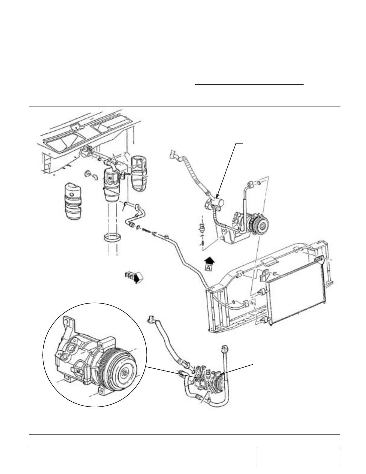
*** IMPORTANT NOTE ***
Certain model trucks have variances in air conditioning line. Before installing the kit
onto your vehicle, see the following schematic to verify the vehicle has the proper lines.
The Vortech kit is compatible with GM part number 15187285. This line can be
removed from the air conditioning compressor. If your vehicle has GM assembly part
number 15708738 Paxton supercharger system WILL NO
T BE COMPATIBLE. This
line assembly is brazed into an aluminum housing and can not be removed. (As shown in
the instructions.)
A/C line and compressor
assembly that is NOT compatible
with the Vortech kit.
(GM 15708738)
A/C LINE AND COMPRESSOR
ASSEMBLY THAT IS COMPATIBLE
WITH VORTECH KIT
(GM 15187285)
DENSO COMPRESSOR

vi
P/N: 4809642
©2004 Paxton Automotive
All Rights Reserved, Intl. Copr.Secured
28SEP04(4809642 v1.2)8.1GMTruck
Y
ou are undoubtedly eager to get started, but
please take a little more time to insure that
your safety is not in jeopardy. A moment’s
lack of attention may cause a serious injury to you,
or to someone else who happens to be standing
around. By following some simple safety precau-
PAXTON Automotive thanks you for your purchase. We welcome your comments and suggestions to help us improve our product.
tions, you can avoid many potential dangers. The
following list is not meant to be a comprehensive
list, but rather it is meant to make you aware of
some of the risks, and encourage you to take a
safety minded approach to your work area.
• Never rely solely on a floor jack when working underneath a
vehicle. Always use jack stands that are rated for the weight of
your vehicle, use them at the recommended lift points, and
place your vehicle in ‘PARK’ or ‘FIRST’ gear with the parking
brake set.
• Always use eye protection when using power tools, such as
drills, saws, and grinders, or when working underneath a vehicle.
• Never smoke, use an open flame, or have spark producing
items around gasoline or flammable objects. Always have a fire
extinguisher that is rated for chemical and electrical fires handy
when working on motor vehicles. Also, make sure that the
extinguisher is fully charged.
• Operate engines only in a well ventilated area. Carbon
Monoxide, gasoline, and solvent vapors are colorless and
sometimes odorless, and may asphyxiate and explode without
warning.
• Always disconnect the battery from your engine before doing
work on the electrical or fuel systems, or doing underdash
work.
• The chemicals used in the vehicle systems, such as oils and
coolants, are poisonous. Clean up any spills immediately, and
dispose of waste materials properly. Pets, wild animals, and
children may die if they ingest the liquid.

vii
P/N: 4809642
©2004 Paxton Automotive
All Rights Reserved, Intl. Copr.Secured
28SEP04(4809642 v1.2)8.1GMTruck
Part No. Description Qty. Part Number Description Qty.
IMPORTANT: Before beginning installation, verify that all parts are included in the kit. Report any shortages or dam-
aged parts immediately.
2001, 2003 8.1L GM Truck
Part No. 1101215
PARTS LIST
8F060-005 HIGH-FLOW INJECTORS 8
1016120 PAXTON NOVI 1200 1
7U100-070 KEY, 3/16 x 3/16 x 7/8 1
2A040-011 PULLEY, RETAINER S/C 1
7B375-110 3/8 24 x 1" HX 1
7K375-040 3/8 AN960 FLAT WASHR PLATED 1
2A021-081 IMPELLER, MACHINED S-TRIM 1
2H100-032 NAME PLATE, NOVI, UNIVERSAL 1
7A250-037 1/4-20 x 3/8 SHCS PLTD 4
7U100-023 DRIVE SCREW #4 x 1/4 2
2A060-030 MATING RING 10MM .096" 0
2A100-020 RETAINER, COMPRESSOR 1
2H375-024 3/8-24 SPIRALOCK, L.H. 6 PT 1
2H248-008 G/C ASSY, NOVI 1200 CW-POLISH 1
7P375-002 3/8 PIPE PLUG STEEL, ZN PLTD 2
7P375-017 3/8 NPT x 1/2 BEADED HSE BRB 1
7P375-001 OIL FEED FITTING, STD 1
7J375-024 3/8" COPPER WASHER 2
7P375-104 PLUG, OIL HOLE 1
008705 2-3/4" BLUE CAP 1
008701 3.325" PLASTIC CAP 1
008703 1/2" PLASTIC CAP 1
008704 7/16" PLASTIC CAP, BLUE 1
7P125-016 1/8 NPT PLUG 2
2A036-333 S/C PULLEY 3.33" 6-GROOVE 1
7W100-020 O-RING, VOLUTE 1
2A046-112 GATES BELT 112" K061120 1
2A100-030 RETAINER, COMPRESSOR 1/2 SIZE 2
4PGE111-021 ASSY, MTG BRKT 8.1L GM TRUCK 1
4PGE010-044 MTNG PLATE, A LARGE 1
4PGE010-034 MTNG PLATE, B SMALL 1
4PGE017-011 2.231" SPACER 1
4PGE017-021 2.739" SPACER 2
4PGE017-031 2.239" SPACER 3
7A375-124 3/8-16 x 1.25 HXHD 5
7F375-044 3/8 WASHER 14
7A375-375 3/8-16 x 3-3/4" HXHD 3
7F375-016 3/8-16 X NYLOCK NUT 5
7A375-375 3/8-16 x 4.75" HXHD 1
7C010-030 10mm x 1.5 30mm 2
7C010-100 10mm x 1.5 x 100 HxHd XX 3
7J010-002 10mm WASHER 7
7C010-091 10mm x 1.5 x 90 FLAT HEAD 1
7A250-103 1/4-20 x 1" SHCS 2
7A250-022 1/4” WASHER 2
4PGE017-041 SPACER, TENSIONER 1
4FM011-052 SPRING TENSIONER 1
4FA016-171 DUST COVER 1
2A017-033 IDLER, SPACER TENSIONER 1
4FH016-150 IDLER 3" FLANGED 1
4PGE017-051 SPACER, IDLER LONG 1
7C010-045 10mm x 1.5 x 45mm HXHD 1
4FA016-150 IDLER 3.5" FLANGED 1
7A375-350 3/8 - 16 x 3.5" HXHD 1
4PGE139-096 INTAKE MANIFOLD ASSY 1
7P375-006 PCV VALVE FORD 1
7P375-045 3/8 NPT 45° STREET ELBOW 1
7P375-047 3/8 LONG NIPPLE 1
8J040-042 BAFFLE, LT1 VETTE 1
7P375-005 3/8 PIPE PLUGS 2
7P375-039 3/8 NPT - 5/8 BARB x 90° 1
7U033-000 5/8 HOSE 2.3’
7P250-045 1/4 NPT - 3/8 BARB 1
7U032-016 3/8 FUEL HOSE, HIGH PRESS 0.125’
4PGE040-050 GASKET, THROTTLE BODY 1
7R001-008 #8 HOSE CLAMP 2
7P250-120 1/4 PIPE PLUG 1
4PGE130-036 OIL DRAIN ASSY 1
7P375-017 3/8" NPT x 1/2 BARB 1
7U030-036 1/2” OIL DRAIN HOSE 1.83’
7R001-008 #6 HOSE CLAMP 2
7U100-055 TIE WRAPS 4
7T560-001 ROTA-BROACH 1
7T560-002 ARBOR ROTA-BROACH 1
4PGE130-026 OIL FEED ASSY 1
7U030-026 1/4" OIL FEED HOSE 5.16’
7P125-026 FITTING 90° 1/8 NPT x -4 1
7S625-000 HEAT SHIELDING 1.5’
7P375-018 3/8 - 1/8 NPT BUSHING 1
7P125-026 FITTING, 90° 1/8 NPT x -4 1
7P375-033 3/8 NPT x 3/8 NPT STREET ELBOW 1
4GL101-002 FUEL SYSTEM ASSY 1
7P625-030 FTG, GM TRUCK FUEL PUMP 1
7P625-031 FTG, GM TRUCK FILTER 1
7R003-027 ADEL CLAMP, 1-11/16" 2
7U030-050 12mm FUEL HOSE 3.28
7R001-008 #8 STNLS HOSE CLAMP 2
8F001-002 INLINE FUEL PUMP, WALBRO 1
7C010-050 10-24 x 1/2 SHCS 1
7F010-024 10-24 NYLOCK NUT 1
7J010-001 #10 WASHER 2
5W001-014 FUSE HOLDER, 10 GAUGE WIRE 1
SW001-011 16-14 GAUGE EYELET 25" HOLE 1
SW001-025 FEMALE SLIDE, INSULATION, MINI 1
SW001-024 MINI FUSE TAP 1
5W001-015 FUSE, BLADE TYPE 20 AMP 1
5W001-017 3/8" RING TERMINAL 12 GAUGE 1
5W001-042 12 GAUGE 3/16" RING TERMINAL 1
5W001-005 3/8" PLASTIC WIRE LOOM 2
5W001-019 SOLDERLESS CONNECTOR 10-12 GA 1
7U100-044 TIE WRAP 4" NYLON 8
8F101-320 RELAY ASSY, LS1 TRUCK 1
8N201-080 WELDED CORE ASSEMBLY 1
8N101-006 ASSY, CORE INLET, 8.1 GM w/BUNG 1
8N003-070 MANIFOLD COOLER 1
8N101-001 ASSY, CORE w/ENDS 1
8N107-050 WATER PUMP ASSEMBLY 1
8F001-402 PIERBURG, WATER PUMP 1
7R003-027 ADEL CLAMP 1-11/16" 1
5W001-025 FEMALE SLIDE MINI 1
5W001-043 12-10 GA x 1/4" RING TERMINAL 3
7A250-050 1/4-20 x .50" SHCS PLTD 2
5W001-013 14-16 GA BUTT CONNECTORS 4
5W001-019 12-10 GA BUTT CONNECTORS 2
7U100-044 4" TIE WRAPS 4
5W001-022 T-SPLICE CONNECTOR 1
7F250-021 1/4-20 NYLOCK NUTS 1
5W001-015 FUSE, BLADE TYPE 20 AMP 1
5W001-005 3/8" PLASTIC WIRE LOOM 2'
5W001-014 FUSE HOLDER 10 GA WIRE 1
7U100-055 TIE WRAP, 6" NYLON 6
5W001-041 12-10 GA MALE SLIDE INSULATED 2
8F101-320 RELAY ASSY, LS1 TRK 1
8N105-040 WATER TANK ASSEMBLY 1
7U038-000 3/4" HEATER HOSE 19'
7R007-001 NYLON CLAMPS 1-1/8" 12
8N055-030 WATER TANK 1
7P500-026 1/2" - 3/4" HOSE BARB 90° 2
7U100-055 TIE WRAP, 6" NYLON 6
7U038-012 HOSE Ø3/4" 90° 4x12" 1
7U030-065 90° MOLDED ELBOW SHORT 1
7P375-075 3/4" HOSE UNION 1
4GL010-060 WATER TANK MOUNTING BRACKET 1
7A250-050 1/4-20 x .50" SHCS 4
7J250-001 1/4 SAE WASHERS 4
8N056-060 SURGE TANK, PLASTIC 1
8N055-050 SURGE TANK CAP 1
7P500-078 1/2 NPT x 3/4 HOSE FIT 2
4GL010-070 SURGE TANK BRKT 1
8N106-060 WATER COOLER ASSEMBLY 1
8N006-010 WATER COOLER (SETRAB) 1

viii
P/N: 4809642
©2004 Paxton Automotive
All Rights Reserved, Intl. Copr.Secured
28SEP04(4809642 v1.2)8.1GMTruck
Part No. Description Qty.
IMPORTANT: Before beginning installation, verify that all parts are included in the kit. Report any shortages or damaged
parts immediately.
2001, 2003 8.1L GM Truck
Part No. 1101215
PARTS LIST
7P500-026 1/2" NPT - 3/4" HOSE BARB 90° 2
2A017-752-03 SPACER, 750 ODx .927 LONG 2
4PGE010-060 BRKT, BOTTOM HEAT EXCH 1
4PGE010-070 BRKT, TOP HEAT EXCH 1
7A250-075 1/4-20 X 3/4" SHCS PLTD 3
7F250-021 1/4-20 NYLOCK NUTS 5
7J250-001 1/4 SAE WASHERS 10
7A250-151 1/4-20 x 1-1/2" SHCS 2
7C060-035 M6 x 1.0 x 35mm 1
2A017-700 SPACER, .70 L x .75 OD x .351 ID 1
4GPE112-020 DISCHARGE ASSY 1
7R002-048 #48 GOLDSEAL HOSE CLAMP 1
7R002-064 #64 GOLDSEAL HOSE CLAMP 1
7S275-300 2-3/4 x 3 SLEEVE 1
7S300-275 3.00" - 2.75" REDUCER SLEEVE 1
7R002-044 #44 GOLDSEAL HOSE CLAMP 3
4PGE012-020 DISCHARGE TUBE 1
4GL012-030 ELBOW 3.88" - 3.00" x 90° 1
4PGE212-010 AIR INLET ASSY, 8.1 TRK 1
7P156-082 5/32 TEE 1
7R002-016 #16 HOSE CLAMP 4
7R002-056 #56 GOLDSEAL HOSE CLAMP 4
7U030-046 5/32" VACUUM LINE 1.5'
7U034-016 1" GS HOSE 0.416'
7U035-001 3-1/2" FLEX HOSE 1.08'
8D001-001 BYPASS VALVE 1
4PGE112-010 INLET TUBE 1
7P375-625 3/8 NPT x 5/8 HOSE BARB 1
4PGE013-010 ROTO-MOLD AIR BOX 1
7S350-200 3-1/2 x 2" SLEEVE 2
8H040-097 AIR FILTER (K&N) 4" FNG 7" LONG 1
7R002-060 #60 HOSE CLAMP 3
7U133-090 1" ID x 90° MOLDED ELBOW SHORT 1
4HS010-060 FLANGE, AIR BOX 1
7A250-056 1/4-20 x .50" SHCS 6
7J250-022 1/4" WASHER 8
7F250-021 1/4-20 NYLOCK NUT 4
7U133-100 1" I.D. x 90° MOLDED TUBE 1
7P100-010 1" PLASTIC CONNECTING BARB 1
7R002-020 #20 HOSE CLAMPS 3
7R003-024 ADEL CLAMP 1
4PGE010-011 Brkt, Airbox Mounting 2
7E010-075 #12 x 3/4" SHTMETAL SCREWS 2

1-1
P/N: 4809642
©2004 Paxton Automotive
All Rights Reserved, Intl. Copr.Secured
28SEP04(4809642 v1.2)8.1GMTruck
Section 1
INITIAL PREPARATION AND REMOVAL
***NOTE***
Before performing any of these steps, note
that it is necessary to remove the refrigerant
from the air conditioning system which should
be performed by a qualified technician using a
refrigerant recycling system.
A. Remove the refrigerant from the A/C sys-
tem.
***IMPORTANT***
Releasing refrigerant into the atmosphere is
environmentally irresponsible and should be
avoided.
B. Drain sufficient amount of coolant to allow
for removal of the radiator reservoir drain
hose.
C. Disconnect the negative cable at the battery.
D. Remove all ducting between the MAF meter
and the throttle body.
E. Remove the upper fan shroud. (If equipped
with an Allison Transmission, remove the
transmission control computer from the fan
shroud.)
F. Remove the accessory drive belt.
G. Remove the factory idler on the driver’s side
just below the alternator.
H. Remove the stock belt tensioner.
I. Remove the bracket on the passengers’ side
head holding the heater hoses.
J. Remove the plastic engine cover that
extends over the engine.
K. Remove the MAF from the factory air box,
then remove the air box.
L. Remove the plate from underneath the origi-
nal air box location.
1.1 INITIAL PREPARATION AND REMOVAL

1-2
P/N: 4809642
©2004 Paxton Automotive
All Rights Reserved, Intl. Copr.Secured
28SEP04(4809642 v1.2)8.1GMTruck
This Page Left Intentionally Blank.
2-1
P/N: 4809642
©2004 Paxton Automotive
All Rights Reserved, Intl. Copr.Secured
28SEP04(4809642 v1.2)8.1GMTruck
Section 2
INTAKE MANIFOLD REMOVAL
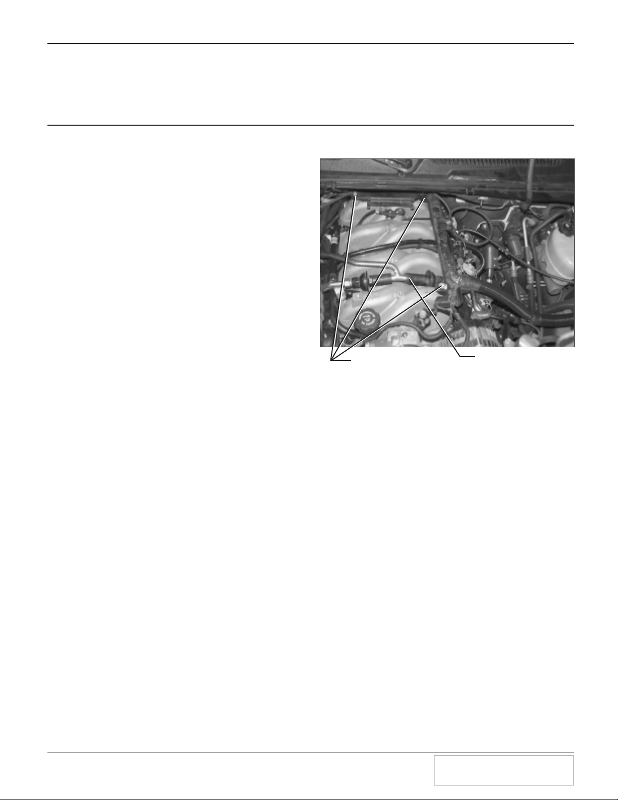
A. Remove the two nuts securing the plastic
bracket that holds the back of the engine
cover on the rear of the intake manifold.
Remove the bracket.
B. Remove both of the studs that are used to
secure the plastic engine cover bracket. This
will un-secure both a small bracket on the
passenger’s side and the rear of the larger
plastic bracket connected to the main injector wiring harness. Continue un-securing the
wiring harness/bracket assembly by removing the screw securing the front of the
bracket. (See Fig. 2-a.)
C. Locate the EGR tubes that run over the
top/front of the intake manifold. (Not all
vehicles will be equipped with EGR tubes.
If so, proceed to the next step.) Remove
the nuts securing the tabs on the EGR tubes.
Follow the tubes down to where they meet
with the exhaust manifolds. Each tube will
be secured to an exhaust manifold with two
screws. Remove the screws securing the
EGR tubes from each of the exhaust manifolds. Disconnect the two EGR tubes from
the central piece and remove them from the
vehicle. Swivel the remaining middle tube to
the passenger’s side to give clearance for the
manifold removal.
D. Disconnect the main wiring harness running
to the fuel injectors.
E. Remove the EGR tube attached to the EGR
motor located on the rear of the intake manifold.
F. Disconnect the plug running to the top of
the EGR motor located on the rear of the
manifold. Disconnect the two plugs running
to the throttle body. Disconnect the plug to
the EVAP service port.
G. Disconnect the fuel lines running to the fuel
rails.
H. Verify everything is disconnected from the
intake manifold. (Some models may vary.)
I. Remove all fasteners securing the intake
manifold to the engine.
J. Slowly lift up on the manifold breaking the
gasket seal and remove it from the engine
compartment.
Fig. 2-a
2.1 INTAKE MANIFOLD REMOVAL
STUDS AND NUTS
TO BE REMOVED
EGR TUBES

2-2
P/N: 4809642
©2004 Paxton Automotive
All Rights Reserved, Intl. Copr.Secured
28SEP04(4809642 v1.2)8.1GMTruck
This Page Left Intentionally Blank.
3-1
P/N: 4809642
©2004 Paxton Automotive
All Rights Reserved, Intl. Copr.Secured
28SEP04(4809642 v1.2)8.1GMTruck
3-1
Section 3
INTAKE MANIFOLD BREATHER/PCV/THROTTLE BODY
GASKET INSTALLATION
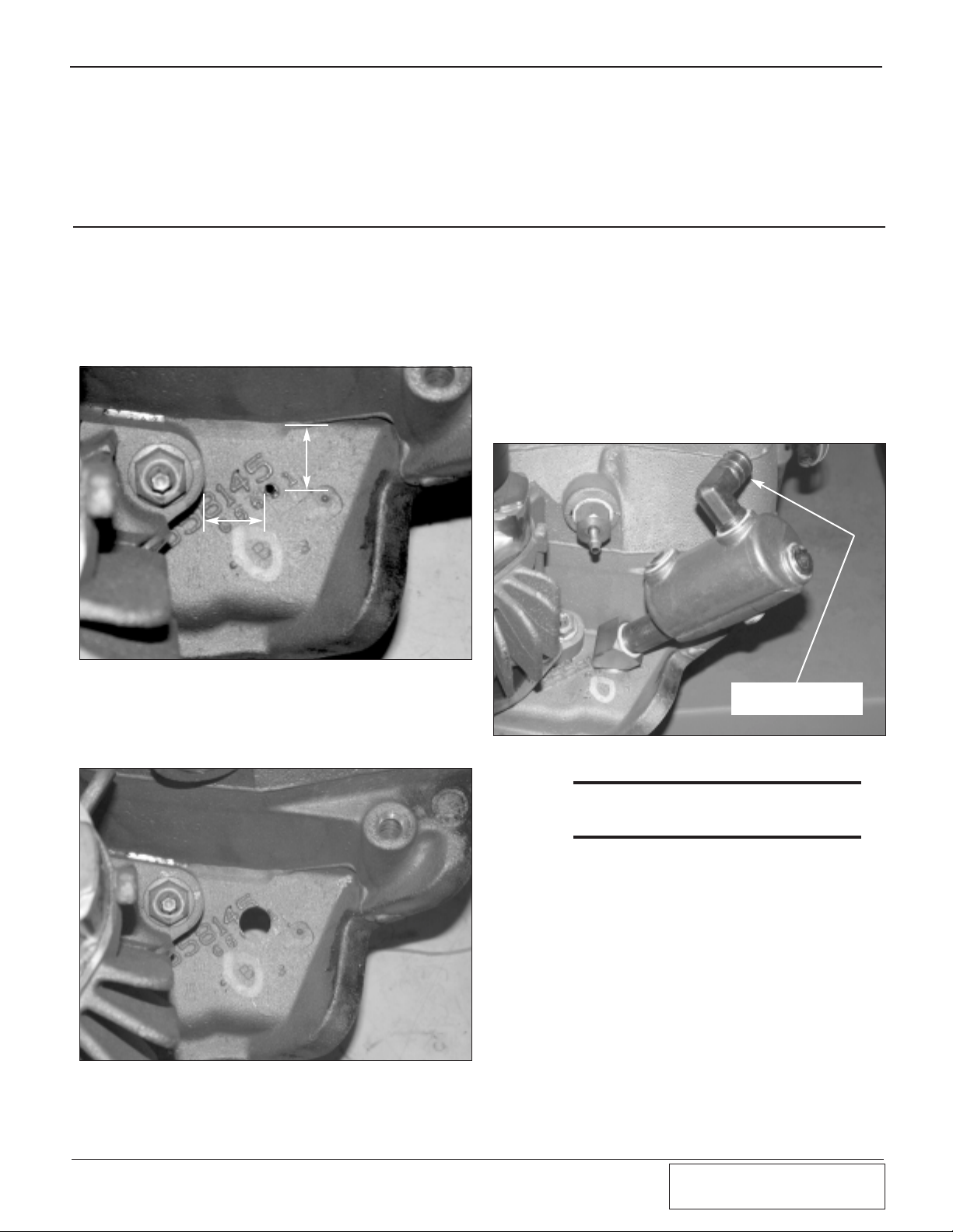
A. Breather Installation:
1. With the manifold removed, locate and
center punch a location on the rear of
the intake manifold near the base of the
EGR motor. (See Fig. 3-a.)
3.1 INTAKE MANIFOLD BREATHER/PCV/THROTTLE BODY GASKET INSTALLATION
Fig. 3-a
Fig. 3-b
***NOTE***
The baffle and barb will not be installed at this
time to aid the EGR tube re-installation.
B. PCV Valve Installation:
1. Locate the small metal breather tube
pressed into the bottom of the cast
manifold. With a pair of pliers, pull out
the metal piece leaving an open hole.
Use a 7/16" drill to enlarge the hole.
2. Drill a 1/8" pilot hole at the center location. Use a 9/16 rota-broach to drill a
hole in the manifold. (See Fig. 3-b.)
3. Tap the hole with a 3/8" NPT tap to
approximately 1/2" deep or until the fitting can be started.
4. Apply a small amount of silicone sealer
to the supplied 3/8" x 45° street fitting
and secure it in the hole. Thread the
3/8" nipple into the street elbow. Orient
the elbow and nipple toward the driver’s side. (See Fig. 3-c.)
Fig. 3-c
ATTACH 5/8" HOSE FROM
180° INLET DUCT
1.8"
.865"

3-2
P/N: 4809642
©2004 Paxton Automotive
All Rights Reserved, Intl. Copr.Secured
28SEP04(4809642 v1.2)8.1GMTruck
Fig. 3-d
3. Using thread sealant secure the 1/4"
NPT to 3/8" barb fitting into in the
hole.
4. Assemble the 1.5" piece of 3/8" hose to
the installed barb along with the supplied PCV valve. Secure both ends of
the hose with the supplied #8 hose
clamps. (See Fig. 3-e.)
Fig. 3-e
C. Throttle Body Gasket Installation:
1. Remove the three nuts securing the
throttle body to the intake manifold.
2. Remove the factory gasket and install
in its place, the supplied gasket.
3. Re-install the throttle body.
2. Tap the hole with a 1/4" NPT tap
approximately 1/2" deep, or until the
fitting can be started. (See Fig. 3-d.)
MODIFIED
HOLE

4-1
P/N: 4809642
©2004 Paxton Automotive
All Rights Reserved, Intl. Copr.Secured
28SEP04(4809642 v1.2)8.1GMTruck
Section 4
FUEL INJECTOR REPLACEMENT
4.1 FUEL INJECTOR REPLACEMENT
A. Fuel Injector Replacement:
1. Disconnect the eight fuel injector
wiring clips and retainers from the fuel
injectors. Release any residual fuel
pressure from the rail by opening the
Schrader valve on the rail.
***NOTE***
Have a fire extinguisher nearby and use
extreme caution.
2. Remove the screws holding down the
factory fuel rail onto the intake manifold. Lift up on the rails evenly removing all eight injectors.
3. Using a small amount of clean engine
oil, lightly lubricate the O-rings on both
ends of the supplied fuel injectors.
Install the new injectors into the fuel
rails with the terminals facing outward.
***NOTE***
For easiest installation, it might be necessary
to remove the retainer clips from the injectors.
Install the injectors into the fuel rail and reinstall the clips onto the injectors.
4. Carefully lower the fuel rail/injector
assembly down onto the intake manifold. Check to see that each injector has
been seated properly into the manifold.
5. Tighten down the fuel rail assembly
with the original bolts.
 Loading...