


DP/N: 4809655 - v1.0 08/16/07
Owners Installation Manual for the
PAXTON NOVI Supercharger
for the
1996-2003 4.6L SOHC
MUSTANG GT
Paxton Automotive . 1300 Beacon Place . Oxnard CA 93033
805 604-1336 . FAX (805) 604-1337

P/N: 4809655
©2007 Paxton Automotive
All Rights Reserved, Intl. Copr.Secured
16AUG07 v1.0 96-03MusGT(4809655v1.0)
ii
FOREWORD
Take note of the following before proceeding:
1. Proper installation of this supercharger kit requires general automotive
mechanic knowledge and experience. Please browse through each step of this
instruction manual prior to beginning the installation to determine if you should
refer the job to a professional installer/technician. Please contact your dealer or
Paxton Automotive for possible installers in your area.
2. This product was designed for use on stock (
un-modified, OEM
) vehicles. The PCM (com-
puter), engine, transmission, drive axle ratios and tire O.D. must be stock. If the vehicle or
engine has been modified in any way, check with Paxton prior to installation and use of this
product.
3. Use only premium grade fuel with a minimum of 91 octane (R+M/2).
4. Always listen for any sign of detonation (knocking/pinging) and discontinue hard use (no boost)
until the problem is resolved.
5. Paxton is not responsible for any clutch, transmission, drive-line or engine damage.
Exclusions from Paxton warranty coverage considerations include, but not limited to:
1. Neglect, abuse, lack of maintenance, abnormal operation or improper installation.
2. Continued operation with an impaired vehicle or sub-system.
3. The combined use of Paxton components with other modifications such as, but not limited to,
exhaust headers, aftermarket camshafts, nitrous oxide, third party PCM programming or other
such changes.
©2007 PAXTON AUTOMOTIVE
All rights reserved. No part of this publication may be reproduced, transmitted, transcribed, or translated
into another language in any form, by any means without written permission of Paxton Automotive.
T
his manual provides information on the installation, maintenance and service of the Paxton
supercharger kit expressly designed for this vehicle. All information, illustrations and specifi-
cations contained herein are based on the latest product information available at the time of
this publication. Changes to the manual may be made at any time without notice. Contact Paxton
Automotive for any additional information regarding this kit and any of these modifications at (805)
888-PAXTON 8:00am-4:30pm PST.
STOP

P/N: 4809655
©2007 Paxton Automotive
All Rights Reserved, Intl. Copr.Secured
16AUG07 v1.0 96-03MusGT(4809655v1.0)
iii
TABLE OF CONTENTS
FOREWORD. . . . . . . . . . . . . . . . . . . . . . . . . . . . . . . . . . . . . . . . . . . . . . . . . . . . . . . .
ii
TABLE OF CONTENTS . . . . . . . . . . . . . . . . . . . . . . . . . . . . . . . . . . . . . . . . . . . . . . .
iii
CONGRATULATIONS ON YOUR PURCHASE . . . . . . . . . . . . . . . . . . . . . . . . . . . . .
iv
SAFETY FIRST. . . . . . . . . . . . . . . . . . . . . . . . . . . . . . . . . . . . . . . . . . . . . . . . . . . . . .
v
TOOL & SUPPLY REQUIREMENTS. . . . . . . . . . . . . . . . . . . . . . . . . . . . . . . . . . . . .
vi
1. DISASSEMBLY . . . . . . . . . . . . . . . . . . . . . . . . . . . . . . . . . . . . . . . . . . . . . . . . . 1-1
1.0 ECM REMOVAL . . . . . . . . . . . . . . . . . . . . . . . . . . . . . . . . . . . . . . . . . . . . . . . . . . 1-1
1.1 AIR INLET REMOVAL. . . . . . . . . . . . . . . . . . . . . . . . . . . . . . . . . . . . . . . . . . . . . 1-1
1.2 COOLANT RESERVOIR REMOVAL . . . . . . . . . . . . . . . . . . . . . . . . . . . . . . . . . . 1-3
1.3 FACTORY TENSIONER AND RELATED PARTS REMOVAL . . . . . . . . . . . . . . . 1-4
1.4 FAN RESISTOR RELOCATION . . . . . . . . . . . . . . . . . . . . . . . . . . . . . . . . . . . . . . 1-6
2. SUPERCHARGER MOUNTING BRACKET ASSEMBLY . . . . . . . . . . . . . . . . . . 2-1
2.0 SUPERCHARGER MOUNTING BRACKET ASSEMBLY . . . . . . . . . . . . . . . . . . 2-1
2.1 SUPERCHARGER INSTALLATION. . . . . . . . . . . . . . . . . . . . . . . . . . . . . . . . . . . 2-4
3. OIL FEED AND DRAIN INSTALLATION . . . . . . . . . . . . . . . . . . . . . . . . . . . . . 3-1
3.0 SUPERCHARGER OIL FEED AND DRAIN (1996-2003 Models) . . . . . . . . . . . . 3-1
3.1 SUPERCHARGER OIL DRAIN INSTALLATION (1996-2003 Models) . . . . . . . . 3-1
4. AIR INLET/DISCHARGE INSTALLATION . . . . . . . . . . . . . . . . . . . . . . . . . . . . 4-1
4.0 FUEL INJECTOR REPLACEMENT (1999-2003 Models Only) . . . . . . . . . . . . . . 4-1
4.1 AIR DISCHARGE DUCT INSTALLATION (1996-2003 Models). . . . . . . . . . . . . 4-1
4.2 AIR INLET INSTALLATION . . . . . . . . . . . . . . . . . . . . . . . . . . . . . . . . . . . . . . . . 4-2
5. IN-TANK FUEL PUMP INSTALLATION. . . . . . . . . . . . . . . . . . . . . . . . . . . . . . 5-1
5.0 FORD 4.6L IN-TANK FUEL PUMP INSTALLATION (1999-2003 Models). . . . . 5-1
5.1 FUEL MANAGEMENT UNIT (1996-1998 Models Only). . . . . . . . . . . . . . . . . . . 5-3
5.2 FORD 4.6L FUEL PUMP INSTALLATION (1999-2003 Models) . . . . . . . . . . . . . 5-5
6. CHECK OUT PROCEDURES. . . . . . . . . . . . . . . . . . . . . . . . . . . . . . . . . . . . . . . 6-1
6.0 CHECK-OUT PROCEDURES. . . . . . . . . . . . . . . . . . . . . . . . . . . . . . . . . . . . . . . . 6-1
6.1 COMPLETED INSTALLATION . . . . . . . . . . . . . . . . . . . . . . . . . . . . . . . . . . . . . . 6-2
APPENDIX . . . . . . . . . . . . . . . . . . . . . . . . . . . . . . . . . . . . . . . . . . . . . . . . . . . . . . . . A-1
A. 1001818 KIT, PARTS LIST . . . . . . . . . . . . . . . . . . . . . . . . . . . . . . . . . . . . . . . . A-2
B. 1011822 ASY, S/C NOVI, REVERSE ROTATION . . . . . . . . . . . . . . . . . . . . . . A-3
C. 1016606 ASY, S/C MTG BRKT (1996-1998 Models Only) . . . . . . . . . . . . . . . A-4
D. 1016609 ASY, S/C MTG BRKT (2000 Models Only) . . . . . . . . . . . . . . . . . . . . A-5
E. 1016616 ASY, S/C MTG BRKT (1999 Models) . . . . . . . . . . . . . . . . . . . . . . . . A-6
F. 1016630 ASY, S/C MTG BRKT (2001-2003 Models). . . . . . . . . . . . . . . . . . . . A-7
G. 1015933 ASY, AIR INTAKE . . . . . . . . . . . . . . . . . . . . . . . . . . . . . . . . . . . . . . . A-8
H. 1017017 ASY, AIR DISCHARGE . . . . . . . . . . . . . . . . . . . . . . . . . . . . . . . . . . . A-9
I. 1019336 ASY, OIL SUPPLY. . . . . . . . . . . . . . . . . . . . . . . . . . . . . . . . . . . . . . . A-10
J. 1019328 ASY, OIL RETURN . . . . . . . . . . . . . . . . . . . . . . . . . . . . . . . . . . . . . . A-11
K. 1015506 ASY, COMPRESSOR BYPASS . . . . . . . . . . . . . . . . . . . . . . . . . . . . . A-12
L. 1015309 ASY, RADIATOR HOSE MODIFICATION. . . . . . . . . . . . . . . . . . . . A-13
M. 1017700 ASY, FUEL CONTROL (1996-1998 Models Only) . . . . . . . . . . . . . . A-14
N. 1016029 ASY, FUEL PUMP. . . . . . . . . . . . . . . . . . . . . . . . . . . . . . . . . . . . . . . A-15
O. 1017734 ASY, FUEL PUMP / IN-TANK . . . . . . . . . . . . . . . . . . . . . . . . . . . . . A-16
P. ----- BELT ROUTING DIAGRAM (2000-2003 Models). . . . . . . . . . . . . . A-17
Q. ----- BELT ROUTING DIAGRAM (1996-1999 Models). . . . . . . . . . . . . . A-18

P/N: 4809655
©2007 Paxton Automotive
All Rights Reserved, Intl. Copr.Secured
16AUG07 v1.0 96-03MusGT(4809655v1.0)
iv
After reading the manual, verify that all
major assembly groups are present in the
main kit box. As you remove a box or bag,
note the identification label and compare it
to the parts list.
PAXTON AUTOMOTIVE makes every effort
to insure that all parts are included in the
box. If you discover that you are missing
any part, or that a part was damaged in
shipping, call PAXTON immediately. DO
NOT begin installation if a part is missing.
Failure to contact PAXTON prior to begin-
ning installation will result in a charge for
the missing part.
We suggest that the engine compartment be
cleaned before the installation. You can
clean the engine with the pressure washer
found at self-serve car washes. Use a safefor-aluminum cleaner/degreaser, and cover
the distributor and any electronics with a
plastic bag to prevent water from entering.
You are undoubtedly eager to get started,
but please take a little more time to insure
that your safety is not in jeopardy. A
moment’s lack of attention may cause serious injury to you, or to someone else who
happens to be standing nearby. By following some simple safety precautions, you can
avoid many potential dangers. The following list is not meant to be a comprehensive
list, but rather it is meant to make you
aware of some of the risks, and encourage
you to take a safety minded approach to
your work area.
C
ongratulations! You have purchased
the finest street supercharger avail-
able for the Mustang GT. The centerpiece of this kit is the High-Efficiency
PAXTON Supercharger, a mechanically
driven centrifugal blower.
This kit comes with all the parts you will
need to install the supercharger. The
instruction manual has been written in order
of sequence, and photographs and drawings
have been included to illustrate the text.
This will allow you quick parts identification and orientation.
The installation will require metric and
SAE sockets and wrenches, a hand drill and
bits, an Air Hammer (and compressor), a
3/8" x 18 NPT tap, screwdrivers, and a supply of buckets for the storing of coolant and
oils.
We suggest that you obtain a copy of a
Mustang shop manual for your model of
car. This may be obtained from your dealer,
or may be ordered by mail from Helm
Publications at (800) 782-4356. Become
familiar with the details of your car’s system. If it is not operating within normal
parameters, we do not recommend the
installation or use of the supercharger.
For the quickest installation time, we suggest that you read this manual thoroughly
before beginning. Make sure that you
understand the process, have identified the
areas of the car that you will be working
on, and have the tools that you will need on
hand. The average installation time is 8 to
10 hours, but your time will depend on your
working conditions, experience installing
superchargers, personal skill level, and preparedness for the job. This estimate does
not include time for the initial vehicle
inspection, cleaning, fine tuning, or troubleshooting. Once again, we recommend reading the manual before beginning the
process. We are available for tech support at
(805) 487-3796, Monday through Friday,
8AM - 4:30 PM PST.

P/N: 4809655
©2007 Paxton Automotive
All Rights Reserved, Intl. Copr.Secured
16AUG07 v1.0 96-03MusGT(4809655v1.0)
v
Never rely solely on a floor jack when
working underneath a vehicle. Always
use jack stands that are rated for the
weight of your vehicle, place them at the
recommended lift points, and place your
vehicle in “PARK” or “FIRST” gear with the
parking brake set.
Always use eye protection when using power
tools, such as drills, saws, and grinders, or
when working underneath a vehicle.
Never smoke, use an open flame, or have spark
producing items around gasoline or flammable
objects. Always have a fire extinguisher that
is rated for chemical and electrical fires handy
when working on motor vehicles. Also, make sure
that the extinguisher is fully charged.
Operate engines only in a well ventilated area. Carbon
Monoxide, gasoline, and solvent vapors
are colorless and sometimes odorless, and
may asphyxiate and explode without
warning.
Always disconnect the battery from
your engine before doing work on the electrical
or fuel systems, or doing underdash work.
The chemicals used in the vehicle systems,
such as oils and coolants, are poisonous. Clean
up any spills immediately, and dispose of
waste materials properly.
PAXTON Automotive thanks you for your purchase. We welcome your
comments and suggestions to help us improve our product.
SAFETY FIRST
P/N: 4809655
©2007 Paxton Automotive
All Rights Reserved, Intl. Copr.Secured
16AUG07 v1.0 96-03MusGT(4809655v1.0)
vi
Before beginning this installation, please read through this entire instruction booklet and the Street
Supercharger System Owner's Manual which includes the Automotive Limited Warranties Program and the
Warranty Registration for m.
Paxton supercharger systems are performance improving devices. In most cases, increases in torque of 3035% and horsepower of 35-45% can be expected with the boost levels specified by Paxton Automotive. This
product is intended for use on healthy, well maintained engines.Installation on a worn-out or damaged engine
is not recommended and may result in failure of the engine as well as the supercharger.Paxton Automotive is
not responsible for engine damage.
Installation on new vehicles will not harm or adversely affect the break-in period so long as factory break-in
procedures are followed.
For best performance and continued durability, please take note of the following key points:
1. Use only premium grade fuel 91 octane or higher (R+M/2).
2. The engine must have stock compression ratio.
3. If the engine has been modified in any way, check with Paxton prior to using this product.
4. Always listen for any sign of detonation (pinging) and discontinue hard use (no boost) until the problem
is resolved.
5. Perform an oil and filter change upon completion of this installation and prior to test driving your vehicle.
Thereafter, always use a high grade SF rated engine oil or a high quality synthetic, and change the oil
and filter every 3,000 miles or less.Never attempt to extend the oil change interval beyond 3,000
miles, regardless of oil manufacturer's claims as potential damage to the supercharger may
result.
6. Before beginning installation, replace all spark plugs that are older than 1 year or 10,000 miles with origi-
nal heat range plugs as specified by the manufacturer and reset timing to factory specifications (follow
the procedures indicated within the factory repair manual and/or as indicated on the factory underhood
emissions tag). Do not use platinum spark plugs unless they are original equipment. Change spar k
plugs at least every 15,000 miles and spark plug wires at least every 50,000 miles.
TOOL & SUPPLY REQUIREMENTS:
• Factory Repair Manual
• 3/8" Socket and Drive Set:SAE & Metric
• 1/2" Socket and Drive Set:SAE & Metric
• 3/8"NPT Tap and Handle
• Adjustable Wrench
• Open End Wrenches: 3/8", 7/16", 1/2", 9/16"
• Center Punch and a 5/8" Tapered Punch
• Ford Springlock 3/8" Fuel Fitting Disconnect Tool
• 5 Quarts SH/CF Rated Quality Engine Oil
• Oil Filter and Wrench
• Flat #2 Screwdriver
• Phillips #2 Screwdriver
• Heavy Grease
• Silicone Sealer
• Drill Motor
• 1/8", 3/16", 27/64" Drill Bits
• 1/2" Tube Bender
• 3/16" Allen Wrench
• Wire Strippers and Crimpers
• Utility Knife
If your vehicle has in excess of 10,000 miles since its last spark plug change, then you will also need:
• Spark Plug Socket
• NEW Spark Plugs
1996-2003
FORD 4.6L SOHC MUSTANG
Installation Instructions
50 State Smog Legal, as per CARB EO #D-195-20
Congratulations on selecting the best performing and best backed
automotive supercharger available today!
S U P E R C H A R G E R S
P/N: 4809655
©2007 Paxton Automotive
All Rights Reserved, Intl. Copr.Secured
16AUG07 v1.0 96-03MusGT(4809655v1.0)
1-1
Fig. 1.1-a
C. Contact the Paxton Service Department for a
Return Authorization Number. Send both the
ECM and supplied credit tag to Paxton using
the enclosed shipping box.
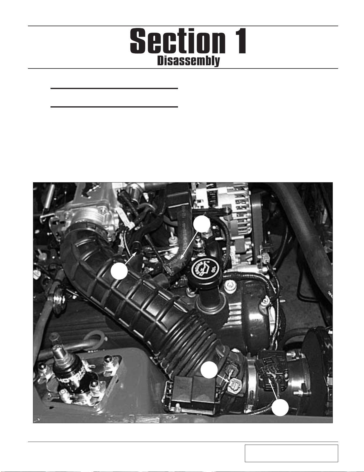
1.1 AIR INLET REMOVAL
A. Before the air intake assembly can be removed,
you must first disconnect the plastic crankcase
breather hose (A) and air idle bypass hose (B).
Unplug the air temperature sensor
1996-2001
Models Only:
(C) and mass air flow sensor
(D). (See Fig. 1.1-a.)
Begin the initial
preparation and disassembly process by
first disconnecting the negative side of the
battery if not already done.
A
B
C
D
1.0 ECM REMOVAL
A. Remove the passenger’s side front kick-panel
from the interior of the vehicle. Remove the
sound deadening material (if any) that is covering the ECM. Remove the plastic ECM
hold-down bracket.
B. Using a 10mm socket or wrench, remove the
harness and plug from the ECM (as you
loosen the bolt, the connector will slowly
release). Remove the ECM from the vehicle.
*** NOTE ***
Before removing the ECM, disconnect the positive
cable from the battery.
P/N: 4809655
©2007 Paxton Automotive
All Rights Reserved, Intl. Copr.Secured
16AUG07 v1.0 96-03MusGT(4809655v1.0)
1-2
Fig. 1.1-b
Fig. 1.1-c
Fig. 1.1-d
Fig. 1.1-e (1996-1998 Models)
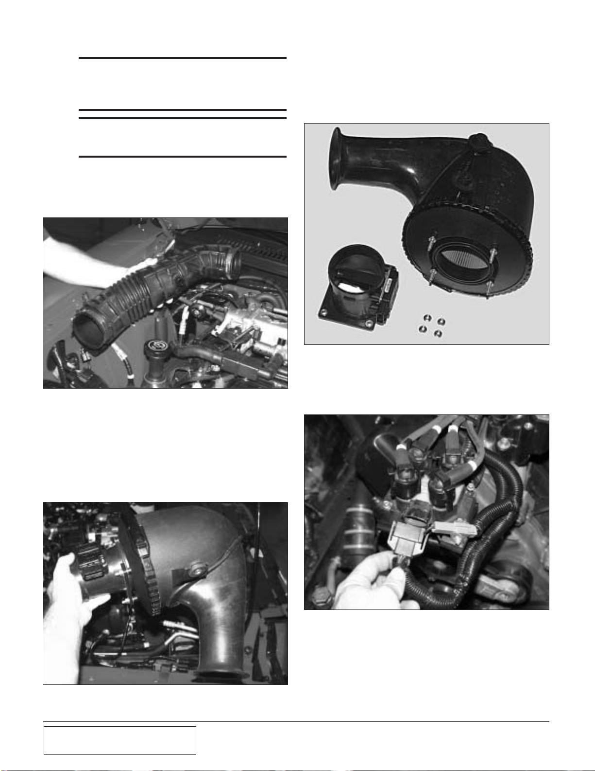
E. Once the assembly is out of the car, use a
10mm socket to remove the mass air flow
sensor from the air filter housing. (See Fig.
1.1-d.) Place the mass air flow sensor aside to
be re-installed in a later step.
1996-1998 Models Only
F. Unplug the coil pack on the passenger’s side
of the engine. (See Fig. 1.1-e.)
C. Remove the air temperature sensor from the
air inlet duct and set it aside. The sensor will
be re-installed in a later step.
D. Use an 8mm socket to remove the single air
filter housing retaining bolt. The air filter and
mass air sensor can then be removed as an
assembly. (See Fig. 1.1-c.)
*** NOTE ***
This manual covers model years 1996-2003. Some
of the photographs and illustrations may be different
but the removal and installation of components are
similar.
*** NOTE ***
2002-2003 models do not have a separate IAT sensor. (The IAT sensor is integrated with the factory
MAF.)
B. Using a flat-head screwdriver or 5/16" nut
driver, loosen the hose clamps at the mass air
flow sensor and the throttle body, and remove
the air inlet hose. (See Fig. 1.1-b.)
P/N: 4809655
©2007 Paxton Automotive
All Rights Reserved, Intl. Copr.Secured
16AUG07 v1.0 96-03MusGT(4809655v1.0)
1-3
G. Use a 7mm socket to remove the four coil
pack bolts and move the coil pack toward the
passenger’s side and out of your way.
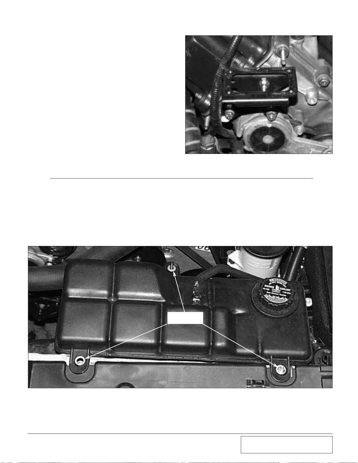
H. Remove the 13mm bolt, nut and stud bolt
securing the coil bracket to the cylinder head.
(See Fig. 1.1-f.)
Fig. 1.1-f
REMOVE THREE
RETAINING NUTS
Fig. 1.2-a
1.2 COOLANT RESERVOIR REMOVAL
A. Drain approximately one gallon of coolant
from the radiator into an appropriate container.
B. Remove the large hose from the coolant reser-
voir and drain the contents of the reservoir
into a container.
C. The coolant reservoir is secured by three nuts.
(See Fig. 1.2-a.) Use a 10mm socket, remove
the reservoir by removing these nuts and place
the reservoir aside.
D. Remove the upper radiator hose and set aside
to be modified in a later step.
P/N: 4809655
©2007 Paxton Automotive
All Rights Reserved, Intl. Copr.Secured
16AUG07 v1.0 96-03MusGT(4809655v1.0)
1-4
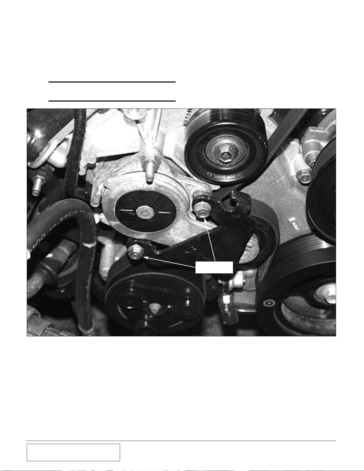
1.3 FACTORY TENSIONER AND RELATED
PARTS REMOVAL
A. Using a 13mm socket, remove the two nuts
securing the tensioner limiting bracket. Set the
bracket and hardware aside as they will not be
reused. (See Fig. 1.3-a.)
*** NOTE ***
Some models and some model years may not have
this bracket. (See Fig. 1.3-a.)
Fig. 1.3-a
REMOVE 13mm
NUTS
P/N: 4809655
©2007 Paxton Automotive
All Rights Reserved, Intl. Copr.Secured
16AUG07 v1.0 96-03MusGT(4809655v1.0)
1-5
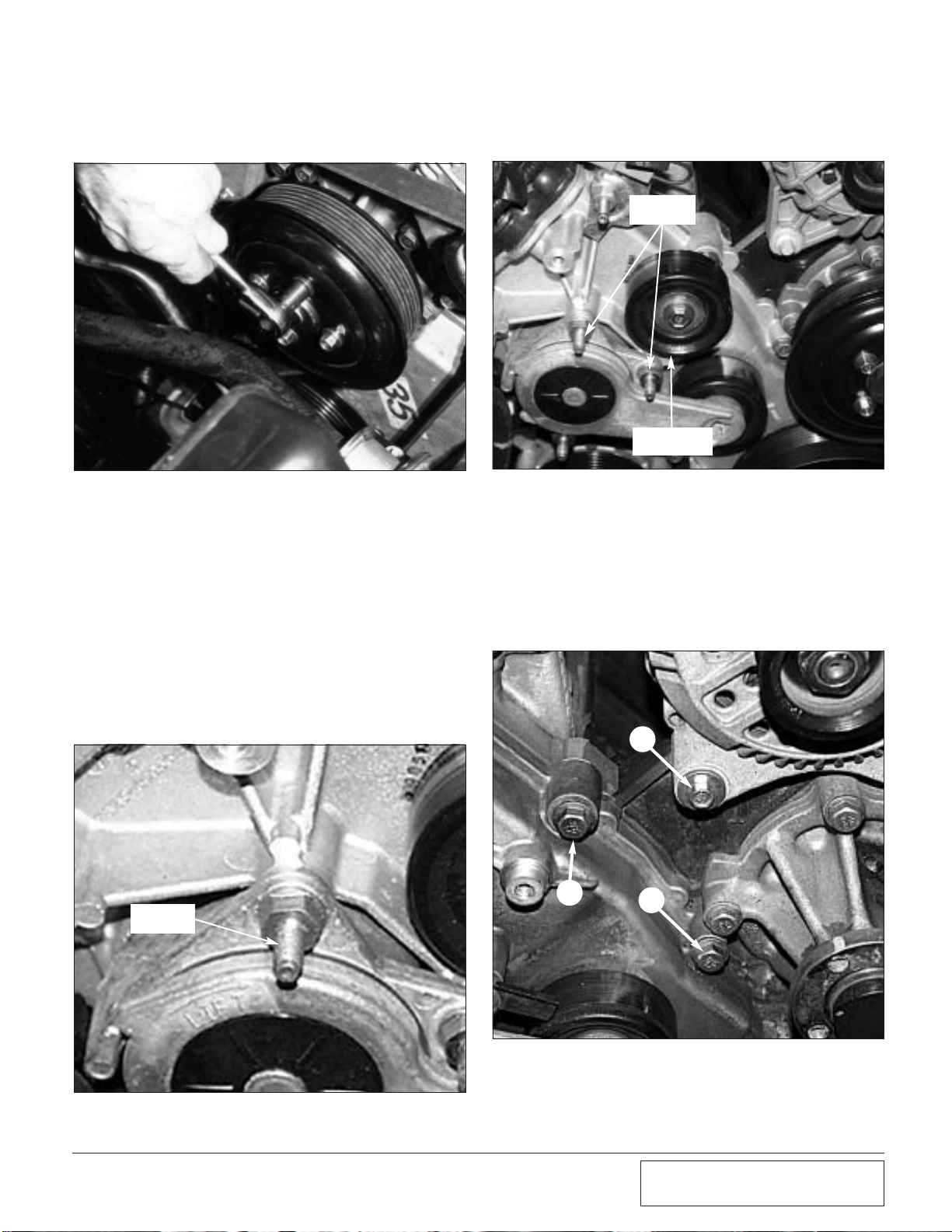
B. Loosen (but do not remove) the four 10mm
bolts on the water pump pulley. (See
Fig. 1.3-b.)
C. Remove the accessory drive belt. Insert a 1/2"
drive ratchet or breaker bar into the square at
the end of the tensioner, and rotate the tensioner. This will relieve the tension on the belt
so it can be removed. It will not be re-used.
D. Using a 13mm wrench, remove the stud bolt
and set it aside. It will not be reused. (See
Figs. 1.3-c, 1.3-d.)
E. Finish removing the four 10mm bolts securing
the water pump pulley and place the pulley
along with its fasteners aside to be reinstalled
in a later step of the installation.
Fig. 1.3-b
F. Use a 13mm socket to remove the idler pulley
located above the belt tensioner. (See Fig.
1.3-d.)
Fig. 1.3-d
Fig. 1.3-c
REMOVE
IDLER PULLEY
13mm
STUD BOLT
13mm
STUD BOLT
Fig. 1.3-e
A
B
C
G. Place the pulley aside to be reused in a later
step.
H. Remove three bolts at the front of the engine
(passenger’s side), (see Fig. 1.3-e), a 10mm
alternator mounting bolt (arrow “A”), and
two 13mm timing cover bolts (arrows “B”
and “C”).
P/N: 4809655
©2007 Paxton Automotive
All Rights Reserved, Intl. Copr.Secured
16AUG07 v1.0 96-03MusGT(4809655v1.0)
1-6
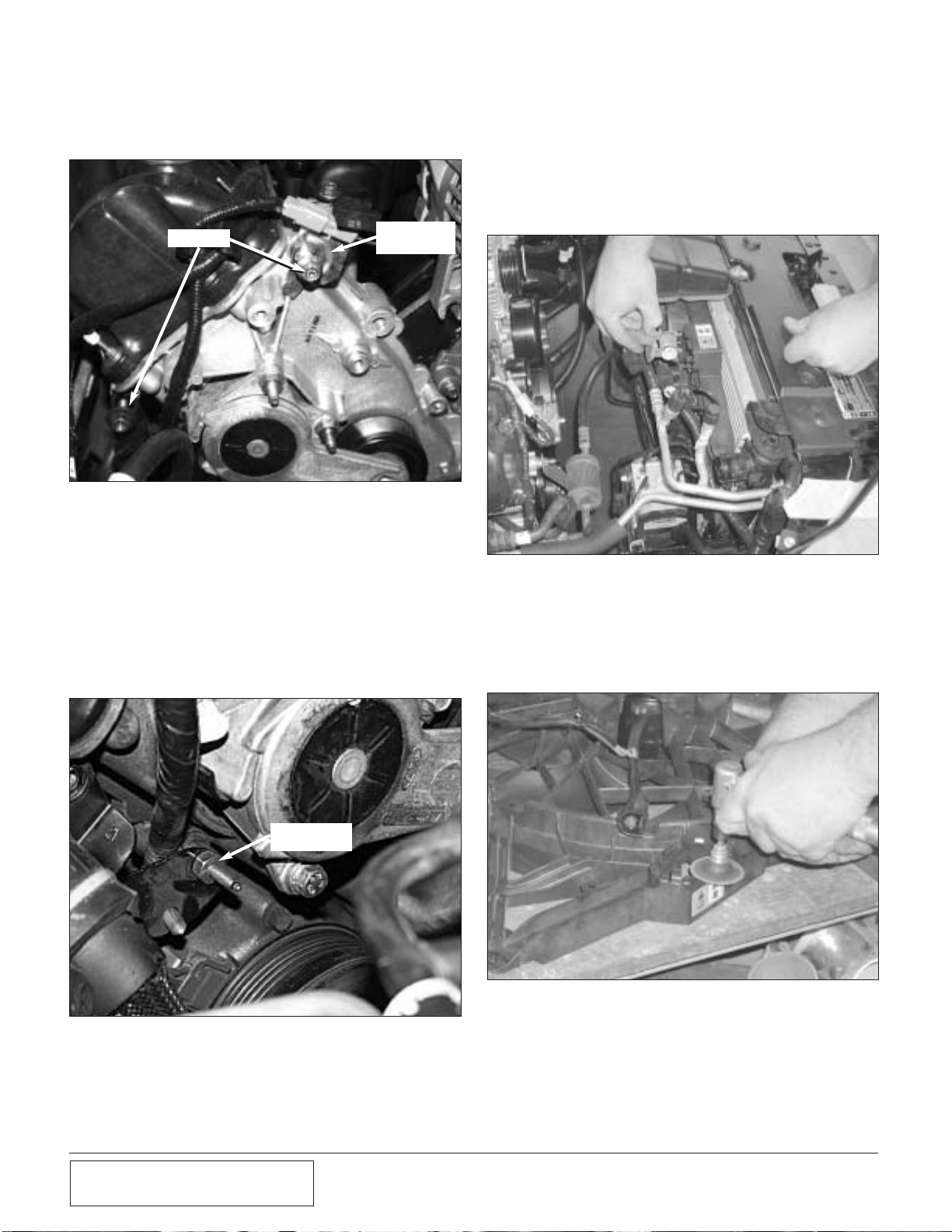
I. Using a 13mm socket, remove the two nuts
and stud bolts located at the top of the passenger’s side cylinder head. (See Fig. 1.3-i.)
Fig. 1.4-a
Fig. 1.4-b
Fig. 1.3-f
Fig. 1.3-g
STUD BOLT TO
BE REMOVED
J. Remove the electrical connector mount. Set
the mount aside to be relocated in a later step.
(See Fig. 1.3-f.)
K. Remove the 13mm nut located to the left of
the belt tensioner (passenger’s side). (See
Fig. 1.3-g.) Push the bracket to the left to gain
access to the stud bolt located at the top of the
passenger’s side cylinder head. Remove the
stud bolt and set aside - it will not be reused.
REMOVE
CONNECTOR
MOUNT
B. Trim the fan resistor mounting tabs on the
fan shroud to provide clearance for the air
intake assembly. (See Fig. 1.4-b.) The fan
shroud should look like this after trimming.
(See Fig. 1.4-c.)
1.4 FAN RESISTOR RELOCATION
2001-2003 Models Only
A. Disconnect the wiring harness from the fan
resistor. (See Fig. 1.4-a.) Remove the clips
holding the fan resistor to the fan shroud.
Attach the fan resistor to the supplied bracket
using the supplied hardware.

P/N: 4809655
©2007 Paxton Automotive
All Rights Reserved, Intl. Copr.Secured
16AUG07 v1.0 96-03MusGT(4809655v1.0)
1-7
Fig. 1.4-c
Fig. 1.4-d
C. Re-attach the fan resistor to the wiring har-
ness to ensure adequate wire length. (See
Fig. 14-d.) Position the supplied fan bracket
and hardware on the passenger’s side of the
lower fan shroud. Mark two mounting points
along the fan shroud and drill the holes.
Attach the mounting bracket with the supplied hardware.

P/N: 4809655
©2007 Paxton Automotive
All Rights Reserved, Intl. Copr.Secured
16AUG07 v1.0 96-03MusGT(4809655v1.0)
1-8
This Page Left Intentionally Blank
P/N: 4809655
©2007 Paxton Automotive
All Rights Reserved, Intl. Copr.Secured
16AUG07 v1.0 96-03MusGT(4809655v1.0)
2-1
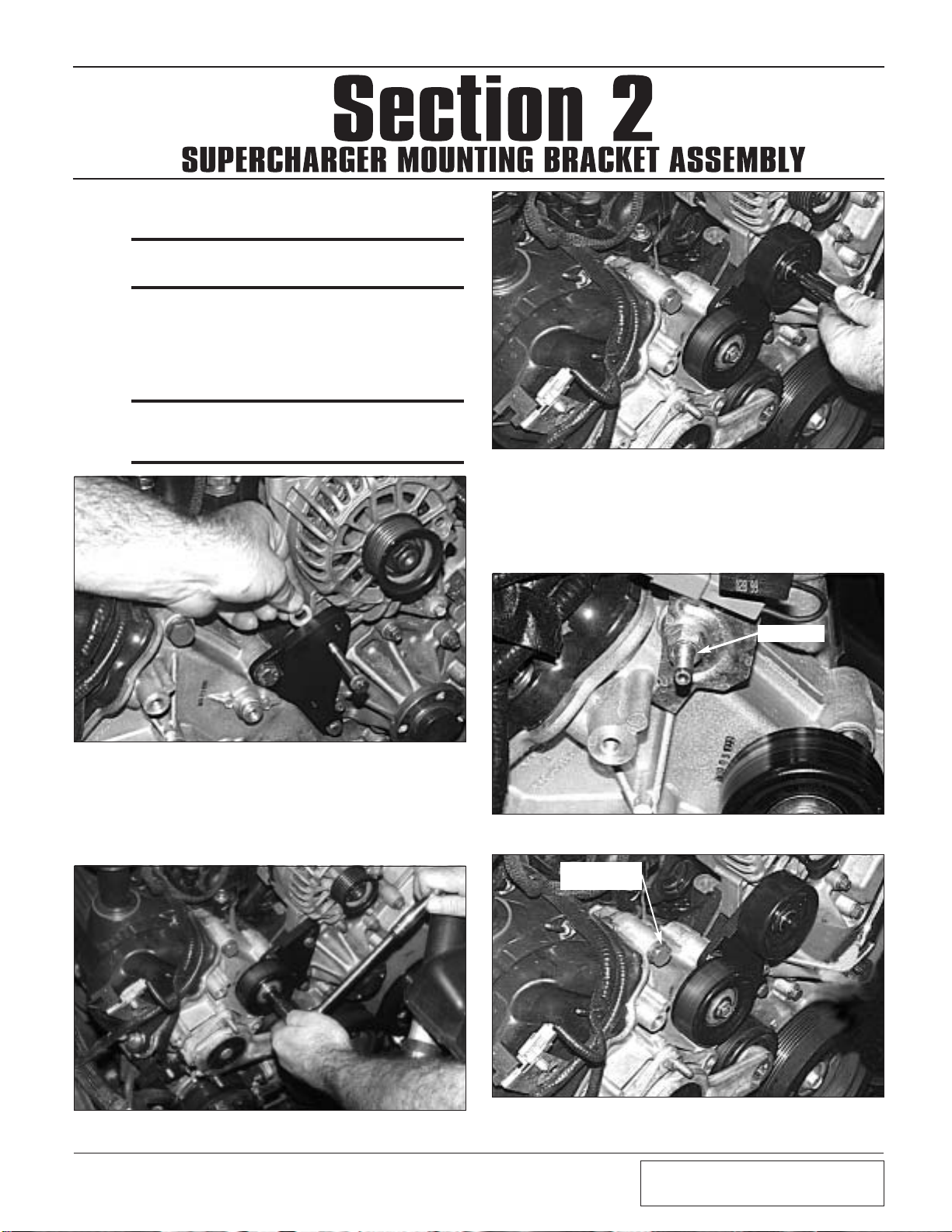
Fig. 2.0-a
C. Replace the bolt stud at the upper right corner
of the timing chain cover (removed during step
1.3-i) (see Fig. 2.0-d) with the supplied fastener. (See Fig. 2.0-e, 1996-1999 Models only.)
B. Re-install the factory idler pulley using the
factory hardware (see Fig. 2.0-b), followed
by the supplied supercharger idler pulley (See
Fig. 2.0-c.)
Fig. 2.0-c
Fig. 2.0-b
Fig 2.0-d
Fig. 2.0-e
1996-1999
MODELS ONLY
BOLT STUD
2.0 SUPERCHARGER MOUNTING
BRACKET ASSEMBLY
*** NOTE ***
See Appendix for the model year’s supercharger
bracket assembly procedure.
A. Install the supercharger idler pulley bracket
using the supplied hardware. Install the provided spacer between bracket and alternator.
(See Fig. 2.0-a.) This operation will be per-
formed on all model years.
*** NOTE ***
This photo is for illustration purposes. It will be easier for you to install this bolt/spacer first, then install
the other two mounting bolts. (See Fig. 2.0-a.)
P/N: 4809655
©2007 Paxton Automotive
All Rights Reserved, Intl. Copr.Secured
16AUG07 v1.0 96-03MusGT(4809655v1.0)
2-2
Fig. 2.0-h (1996-1999 Models)
Fig 2.0-f
Fig 2.0-g / 2000-2003 Models
*** NOTE ***
Before installing the outer supercharger mounting
plate, the supplied accessory’s supercharger drive
belt must be installed.
*** NOTE ***
2001-2003 models must have the accessory drive
belt installed BEFORE the support bracket is installed.
*** NOTE ***
If possible, use a proper tubing bender for this step.
If one is not available, the line can be bent by hand,
but extreme care must be taken as the refrigerant
within the line is under very high pressure. In any
case, use a pair of heavy gloves and eye protection to
prevent injury in the event of a ruptured line.
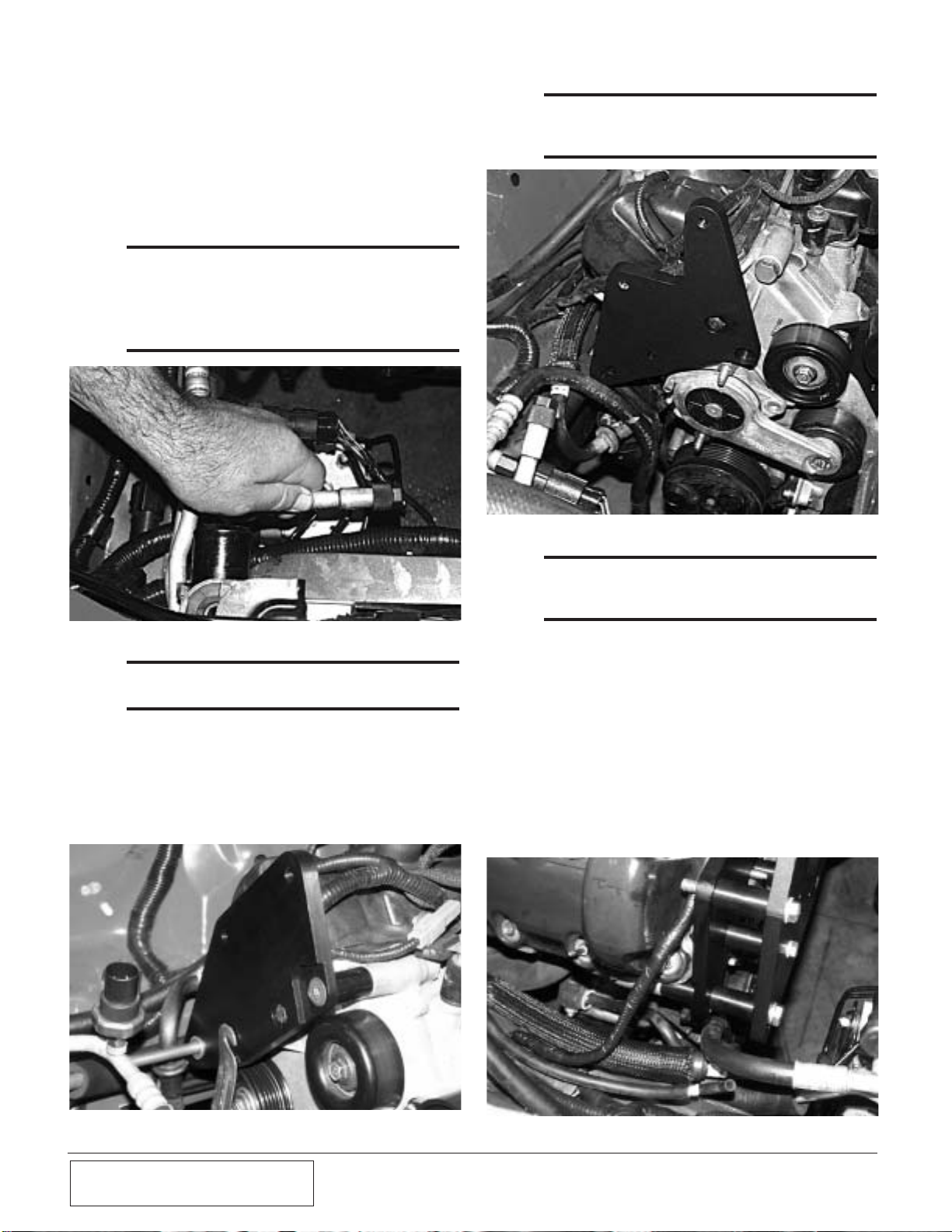
D. Before installing the main supercharger brack-
et, the A/C refrigerant refilling port must be
bent from its upright position downward so
that the cap is facing the driver’s side fender.
(See Fig. 2.0-f.) Note that this operation will
be performed on all model years
except
model
year 2000. This hose assembly will be
replaced with the provided A/C hose assembly.
Fig. 2.0-i / 1996-1999 Models
F. Mount the main supercharger bracket using
the two 3/8-16 x 2.75" bolts and spacers in the
upper portion of the bracket. Install the 8mm
bolt and spacer in the lower middle portion of
the bracket. (See Appendix “C” for 1999
Models, Appendix “D” for 2000 Models,
Appendix “F” for 2001-2003 Models,
Appendix “E” for 1996-1998 Models.) Install
the lower bolt and two spacers. One between
the support and main brackets, the other
between the support bracket and the cylinder
head. (See Fig. 2.0-i.)
*** NOTE ***
1996-1998 Models Only - The A/C line bracket
should be placed between the spacer and the cylinder
head. (See Fig. 2.0-l.)
E. Install the supercharger rear support bracket
with the supplied 8mm bolt, leaving it fingertight. It will be necessary to move this bolt
when the main supercharger bracket is mounted. (See Figs. 2.0-g 2000-2003, 2.0-h. 1996-
1999)

P/N: 4809655
©2007 Paxton Automotive
All Rights Reserved, Intl. Copr.Secured
16AUG07 v1.0 96-03MusGT(4809655v1.0)
2-3
Fig. 2.0-k
Fig. 2.0-j
G. Reinstall the water pump pulley removed in
an earlier step. (See Fig. 2.0-j.)
*** NOTE ***
The belt must be routed BEFORE this bolt and spacer
are installed.
Route the supercharger and accessory drive
belt.
*** NOTE ***
On 2000-2003 models the drive belt needs to be
routed before the rear S/C mounting plate is installed.
Fig. 2.0-m
Fig. 2.0-l
Completed Supercharger Mounting Bracket

P/N: 4809655
©2007 Paxton Automotive
All Rights Reserved, Intl. Copr.Secured
16AUG07 v1.0 96-03MusGT(4809655v1.0)
2-4
*** NOTE ***
The hose clamp screw head should be parallel to the
supercharger mounting base.
B. Locate the 1/8" x -4 x 90° oil feed fitting.
(See assembly
1019327
.) Install the fitting
into the supercharger oil feed.
*** NOTE ***
Use only clean oil to seal this fitting. Teflon paste or
Teflon tape may become dislodged and plug the
supercharger oil feed.
A. Install the supercharger oil return line (see
assembly
1019328
) to the supercharger drain
fitting and secure with the hose clamp provided.. (See Fig. 2
.1-a.)
Fig 2.1-a
C. Remove the drive belt from the alternator pul-
ley.
D. Install the supercharger into the main bracket,
while looping the drive belt around the supercharger pulley. (See Fig. 2
.1-b.)
E. Install the six 3/8-16 x 1.25" bolts and wash-
ers. Tighten the supercharger mounting bolts.
Once the supercharger is installed, release the
belt tensioner and loop the belt back around
the alternator pulley.
*** NOTE ***
1996-1998 model year cars will require a coil bracket
and a different spacer. One of the 3/8-16 x 1.25" bolts
must be replaced by a 3/8-16 x 1.0" bolt to clear the
coil bracket.
Fig. 2.1-b
Fig. 2.1-c
2.1 SUPERCHARGER INSTALLATION
OIL FEED
FITTING
H. Install the spacer and coil mounting bracket
after installing the supercharger.

P/N: 4809655
©2007 Paxton Automotive
All Rights Reserved, Intl. Copr.Secured
16AUG07 v1.0 96-03MusGT(4809655v1.0)
3-1
A. Your Paxton Automotive NOVI supercharger
uses pressurized engine oil for lubrication.
Use an oil sending unit socket (Snap-On
tools; part number 6152 or equivalent) to
remove the oil sending unit on the underside
of the oil filter housing. (See Fig. 3.0-a.)
Fig. 3.0-a
B. Install the supplied 1/4"NPT x 1/4"NPT
STRT-T fitting. DO NOT USE TEFLON
TAPE or paste. The sealant may become dislodged and clog the supercharger oil feed orifice and cause damage to the supercharger.
C. Once installed, the junction fitting should be
oriented so that the opening faces toward the
front of the car. (See Fig. 3.0-b.)
D. Install the oil sending unit onto the end of the
brass junction. Install the 1/4" x -4 x 90° fitting into the side of the brass junction, and
orient this fitting to face towards the driver’s
side frame rail. Attach the supplied length of
braided stainless steel feed line, and route
upwards to the 90° fitting on the supercharger.
*** NOTE ***
Be sure to stay clear of any moving parts or coolant
hoses (engine vibration can cause the stainless line
to chafe the rubber coolant hose, creating a leak over
time).
E. Install the line, and tighten moderately - no
sealant is required. (See Fig. 3.0-b.)
A. Mark the front of the oil pan 1-1/8" below the
pan rail and between the the two pan rail bolts,
directly in the center of the small “hump”.
(See Appendix “G”.) Drill a pilot hole with a
3/16" drill bit. (See Fig. 3.1-a.)
Fig 3.1-a
B. Smear the drill bit with heavy grease first to
prevent small metal particles from falling into
the pan.
C. Once the hole has been drilled, insert a
straight length of welding rod or heavy wire
(such as a coat hanger) into the hole approxi-
mately three inches to make sure no interference is encountered. If the path is blocked,
turn the engine over until the pathway is clear.
Fig. 3.0-b
3.1 SUPERCHARGER OIL DRAIN
INSTALLATION (1996-2003 Models)
3.0 SUPERCHARGER OIL FEED AND
DRAIN (1996-2003 Models)

P/N: 4809655
©2007 Paxton Automotive
All Rights Reserved, Intl. Copr.Secured
16AUG07 v1.0 96-03MusGT(4809655v1.0)
3-2
NO DEEPER THAN THIS LINE
Fig. 3.1-b
Fig. 3.1-c
Fig. 3.1-d
D. Next, apply a small amount of anti-seize
lubricant to the tip of the punch, and insert it
into the pilot hole. Using the appropriate tool,
(an air hammer works the best), use small
bursts until the punch is inserted up to its
shoulder. The finished hole size should be
9/16". (See Fig. 3.1-b.)
*** NOTE ***
Do not use hand tools. Using an ordinary hammer
will dent the pan. Use extreme caution not to make
the hole to big, or the drain fitting will not fit fter tapping the pan.
E. Apply a liberal amount of heavy grease to a
3/8-18 NPT tap (not included), and gradually
thread into the hole. Clean the threads using a
clean rag and an approved solvent, such as
carburetor cleaner.
F. Apply an ample amount of silicone RTV to
the threads of the supplied 3/8"NPT x -8 fitting and insert into the hole. Be careful not to
over-tighten. (See Fig. 3.1-c.)
G. Install the supplied drain-back hose fitting so
that the elbow is oriented toward the passenger’s side, away from the harmonic balancer/
crank pulley. Attach the supercharger drain
hose and fitting installed on the supercharger
during an earlier step. (See Fig. 3.1-d.)

P/N: 4809655
©2007 Paxton Automotive
All Rights Reserved, Intl. Copr.Secured
16AUG07 v1.0 96-03MusGT(4809655v1.0)
4-1
4.0 FUEL INJECTOR REPLACEMENT 19992003 Models Only
B. Install the supplied length of rubber hose to
the end of the hard crank case ventilation line
that runs from the driver’s side valve cover
across the engine, (See Fig. 4.1-b.)
Fig. 4.1-b
Route the hose over the passenger’s side valve
cover and towards the front of the engine.
This hose will be attached to the 3/8"NPT x
3/8" x 90° barbed fitting installed in the air
inlet duct. (See Appendix “G” for fitting and
hose location.) Please note that this hose will
be attached in a later step of the installation.
C. Install the idle air control valve to the throttle
body housing with the original hose, and to the
discharge tube with the supplied length of rubber hose and hose clamps. (See Fig. 4.1-c.)
A. Disconnect the eight fuel injector wiring clips
and retainers from the fuel injectors. Release
any residual fuel pressure from the rail by
opening the schrader valve on the rail.
B. Remove the four 8mm headed bolts holding
the factory fuel rail onto the intake manifold.
Lift up on the rails evenly, removing all eight
injectors.
C. Using a small amount of clean motor oil,
lightly lubricate the O-rings on both ends of
the supplied fuel injectors.
D. Install the new injectors into the fuel rails
with the terminals facing outward.
E. Carefully lower the fuel rail/injector assembly
down onto the intake manifold. Check to see
that each injector has been seated properly
into the manifold.
F. Tighten down the fuel rail assembly with the
original bolts and attach the injector plugs to
the injector terminals.
*** NOTE ***
Make sure injector retainers are secure and properly
installed. Recheck after cycling the fuel system.
Fig. 4.1-c
4.1 AIR DISCHARGE DUCT INSTALLATION (1996-2003 Models)
A. Install the discharge tube assembly as shown,
using the supplied rubber sleeves and stainless
steel clamps. (See Fig. 4.1-a.)
Fig. 4.1-a

P/N: 4809655
©2007 Paxton Automotive
All Rights Reserved, Intl. Copr.Secured
16AUG07 v1.0 96-03MusGT(4809655v1.0)
4-2
Fig. 4.2-a
*** NOTE ***
The MAF mounting bracket you receive may be different than what is shown but the assembly is the
same.
A. Assemble the MAF, mounting bracket,
MAF/air filter adapter and air filter. (See Fig.
4.2-a & Appendix “G”.)
B. Using the supplied 1/4-20 hardware, mount
the MAF meter to the MAF bracket and
secure. (See Fig. 4.2-a.)
** NOTE ***
Remove the factory MAF screen before attaching the
meter to the new bracket.
4.2 AIR INLET INSTALLATION
VIEW FROM INSIDE ENGINE
COMPARTMENT
(Steel inner fender not shown for
ease of description)
FACTORY AIR
TEMPERATURE SENSOR
(NOT ON 2002+ MODELS)
3-1/2" ELBOW
SLEEVE
#56 CLAMPS
FACTORY
STUDS & NUTS
INSIDE
RIGHT FRONT
PASSENGER
FENDERWELL
FRONT

P/N: 4809655
©2007 Paxton Automotive
All Rights Reserved, Intl. Copr.Secured
16AUG07 v1.0 96-03MusGT(4809655v1.0)
4-3
C. Attach the supplied K & N air filter, 3-1/2"
sleeve, 90° x 3-1/2" elbow and #56 hose
clamps to the MAF and secure.
*** NOTE ***
1996-2001 models use the 90° x 3-1/2" plastic inlet
elbow with the hole and grommet in the side. 2002+
models use the 90° x 3-1/2" plastic elbow without a
hole in the side. Both elbows have been supplied.
D. (1996-2001 Models only.) Insert the factory
air temperature sensor into the rubber grommet located on the side of the 90° elbow.
Lubricate for easier fit. (See Fig. 4.2-a.)
*** NOTE ***
2002-2003 models do not have a separate IAT
sensor.
E. From beneath the vehicle, remove the two
factory nuts and washers from the passenger’s
side lower fender valence. Mount the
MAF/bracket assembly onto the existing studs
using the same washers and nuts originally
removed.
F. Using a #52 hose clamp, connect the piece of
3-1/2" flex hose to the elbow attached to the
MAF meter and route it through the opening
in the right side inner fender toward the
supercharger. Make sure the 3-1/2" flex hose
does not contact or rub on the edge of the
inner fender opening. (Eventual hose failure
will result if the hose is not properly routed.)
G. Route the factory temperature sensor and
MAF sensor connectors out through the inner
fender opening. Reattach the connectors to the
relocated sensors.
H. Install the bypass valve assembly on the
underside of the secondary intake tube. (See
Fig. 4.2-c.) (See Appendix “J” for bypass
assembly procedure.)
Fig. 4.2-b
Fig. 4.2-c
ATTACH TO
DISCHARGE DUCT
I. Place the secondary intake tube/bypass valve
assembly on the supercharger inlet and attach
it to the flex hose. Attach the other end of the
bypass valve to the discharge tube. Connect
the hose that was previously installed on the
hard plastic crank case ventilation line to the
brass fitting on the intake tube. Tighten the
clamps. The finished installation appears as
shown. (See Fig 4.2-d.)
Fig. 4.2-d
BRASS FITTING TO
VALVE COVER VENT

P/N: 4809655
©2007 Paxton Automotive
All Rights Reserved, Intl. Copr.Secured
16AUG07 v1.0 96-03MusGT(4809655v1.0)
4-4
J. Remove the 2" bolts securing the lower reser-
voir bracket. Reinstall the support bracket
using one of the existing holes and factory
fasteners and the self-tapping screw provided.
K. Re-install the stock coolant reservoir. (See
Fig. 4.2-f.)
*** NOTE ***
The Novi 2000 application will have spacers provided
to move the coolant reservoir to gain clearance for
the supercharger.
Fig. 4.2-f
Fig. 4.2-e
COOLANT RESERVOIR
RELOCATION BRACKETS

P/N: 4809655
©2007 Paxton Automotive
All Rights Reserved, Intl. Copr.Secured
16AUG07 v1.0 96-03MusGT(4809655v1.0)
5-1
5.0 FORD 4.6L IN-TANK FUEL PUMP
INSTALLATION (1999-2003 Models)
A. Raise the rear of the car and support it with
jack stands.
B. Open the fuel door and remove the fuel cap
and the three filler neck screws using a 10mm
socket.
C. Remove the fuel filter inlet line with a 3/8"
spring-lock tool.
D. With the weight of the fuel tank supported
with a jack, remove the bolts securing the two
fuel tank straps.
E. Slowly lower the fuel tank, allowing it to lean
over with the filler side up until the electrical
connections leading to the center mounted
fuel pump are revealed. Disconnect these two
electrical connections.
F. Remove the six bolts securing the fuel pump
access cover (on top of the fuel tank) with an
8mm wrench. Depress the two clips securing
the plastic fuel pump enclosure and slide it
out of the tank. The fuel sender float is
attached to the fuel pump enclosure and must
be handled with care. Ensure that the tank has
been lowered enough to remove the fuel
pump enclosure.
G. Remove the two screws securing the plastic
fuel pump outlet manifold to the enclosure
cap. Pull the manifold up and away from the
fuel pump.
H. Remove the three screws securing the fuel
pump enclosure cover using a 3/16" nut driver
and remove the cover.
I. Remove the stock fuel pump from its enclo-
sure. Separate the rubber pump support from
beneath the filter and install it on the supplied
pump. Secure the support with the new filter
provided.
J. Using the supplied fuel pump, reassemble the
fuel pump assembly and canister with cap.
K. Reinstall the canister assembly into the fuel
tank. Reattach the electrical connections.
L. Reinstall the fuel tank, reconnect the fuel fil-
ter inlet line, reattach the fuel filler neck, and
reinstall the fuel pump.
M. Turn the ignition key on and check the fuel
pump for leaks.

P/N: 4809655
©2007 Paxton Automotive
All Rights Reserved, Intl. Copr.Secured
16AUG07 v1.0 96-03MusGT(4809655v1.0)
5-2
This Page Left Intentionally Blank

P/N: 4809655
©2007 Paxton Automotive
All Rights Reserved, Intl. Copr.Secured
16AUG07 v1.0 96-03MusGT(4809655v1.0)
5-3
Fig. 5.1-a
A. Position the fuel management unit (FMU)
against the inner fender ahead of the right side
shock tower about an inch from the top. Mark
and drill two holes in the inner fender to
mount the FMU. Secure with the sheet metal
screws provided. (See Figs. 5.1-a, 5.1-b,
5.1-c.)
5.1 FUEL MANAGEMENT/UNIT (1996-1998
Models Only)
FUEL
MANAGEMENT
UNIT (FMU)
VACUUM LINE
OUTLET
INLET
FACTORY
QUICKDISCONNECT
FITTING
FUEL RETURN LINE
FACTORY
SPRINGLOCK
CONNECTOR
FILTER
T-REX
FUEL TANK
FACTORY
REGULATOR
ENGINE
FUEL FEED LINE

P/N: 4809655
©2007 Paxton Automotive
All Rights Reserved, Intl. Copr.Secured
16AUG07 v1.0 96-03MusGT(4809655v1.0)
5-4
B. Disconnect and discard the factory rubber
fuel return line running from the fuel rail (the
return line DOES NOT have a pressure test
fitting on it) to the steel return line (the smaller of the two) located behind the right side
shock tower using a spring lock disconnect
tool.
C. Connect the FMU inlet hose (the hose that
goes to the 90° fitting on the side of the
FMU) to the return side of the factory fuel
regulator on the fuel rail.
D. Connect the FMU outlet hose (attaches to the
center fitting on the bottom of the unit) to the
steel return line running to the tank. Make
sure the hose end is securely “snapped” onto
factory fuel return line.
E. Secure the fuel lines away from abrasion and
exhaust heat with the tie-wraps provided.
F. Attach the supplied length of 5/32" vacuum
hose to the fitting on top of the FMU.
Connect the opposite end of the hose to the
factory fuel regulator vacuum connection
using the 5/32" TEE provided.
Fig. 5.1-b
Fig. 5.1-c
PASSENGER’S SIDE
ENGINE COMPARTMENT
STRUT
SHOCK
TOWER
FMU
TOP VIEW

P/N: 4809655
©2007 Paxton Automotive
All Rights Reserved, Intl. Copr.Secured
16AUG07 v1.0 96-03MusGT(4809655v1.0)
5-5
B. Connect the power wire from the relay
(Terminal #30) to the battery positive (+) terminal. (See Fig. 5.2-d.)
Fig. 5.2-d
C. Locate the wiring harness connection from the
battery. Connect the gray trigger wire from
the relay (Terminal #86) with the supplied
quick connector to the solid red wire coming
from the wiring harness connection. (See Fig.
5.2-e.)
D. Route the red wire from the relay (Terminal
#87) through the provided split loom along
the back of the firewall, across to the passenger’s side, and along the other components to
the fuel tank where it will be connected to the
additional fuel pump.
Fig. 5.2-e
POWER FROM
RELAY TO
TERMINAL
QUICK
CONNECTOR
POWER WIRE TO
TRIGGER RELAY
5.2 FORD 4.6L FUEL PUMP INSTALLA-
TION (1996-1998 Models Only)

P/N: 4809655
©2007 Paxton Automotive
All Rights Reserved, Intl. Copr.Secured
16AUG07 v1.0 96-03MusGT(4809655v1.0)
5-6
E. Disconnect the factory fuel line at the fuel fil-
ter using the supplied tool. Connect the male
fitting from the fuel pump to the line that you
removed from the fuel filter. Connect the
female end from the fuel pump to the fuel filter.
F. The in-line auxiliary fuel pump is installed
next. Remove the spare tire from the well in
the trunk. Mount the pump/bracket assembly
by drilling two 1/4" holes in the spare tire
well using the bracket as a template.
1. Placement should be as close as possible to
the fuel tank while still providing access to
the mounting bolts with a socket.
G. From inside the trunk (not underneath), use a
grinder or a piece of course sandpaper to
remove the paint from around one of the holes
you just drilled. This will ensure a good
ground point that is not exposed to the elements.
H. From underneath the car, connect the pump
ground wire to this hole as you secure the
pump to the spare tire well using the supplied
fastening bolts. (See Fig. 5.2-f.)
I. Connect the wire from the relay to the pump
power terminal.
Fig. 5.2-f

P/N: 4809655
©2007 Paxton Automotive
All Rights Reserved, Intl. Copr.Secured
16AUG07 v1.0 96-03MusGT(4809655v1.0)
6-1
A. Inspect all wiring harnesses and electrical connections. Make sure
that all items are properly routed, connected and secured.
B. Check all hoses, lines, and fittings for properly secured connec-
tions.
C. Make certain all fasteners, brackets, and clamps are installed and
properly tightened.
D. Check the serpentine accessory belt and supercharger drive belts
for proper tension and alignment.
E. Cycle ignition key from “off” to the “on” position.
F. Check the entire fuel system for possible leaks.
G. Start the engine and verify that the oil pressure is within normal
range.
H. Allow the engine to come up to normal operating temperature.
I. Check the coolant level in the coolant recovery bottle and top off
as needed.
J. Check for the following:
• Fluid Leaks
• Fluid Levels
• Belt Slippage
• Throttle Response
6.0 CHECK-OUT PROCEDURES
We know that you are anxious to get out and drive your
new vehicle, but please take a little bit more time to
perform these simple check-out steps.
Now that the work is done, it’s time to enjoy the results
of your efforts.
PAXTON Automotive
wants to thank
you for choosing our product, and wants to remind you
that the performance and response of your vehicle will
now be different from that to which you have been
accustomed. Please drive cautiously until you feel comfortable with the handling of your vehicle.
Please see the service manual included in your kit for
information on the service and maintenance of your
PAXTON Supercharger
. Belt tightening, troubleshooting, special tuning requirements, and warranty
information is also included in the Service Manual.

P/N: 4809655
©2007 Paxton Automotive
All Rights Reserved, Intl. Copr.Secured
16AUG07 v1.0 96-03MusGT(4809655v1.0)
6-2
Fig. 6.1-a
6.1 COMPLETED INSTALLATION

P/N: 4809655
©2007 Paxton Automotive
All Rights Reserved, Intl. Copr.Secured
16AUG07 v1.0 96-03MusGT(4809655v1.0)
A-1
Please realize that PAXTON Automotive is constantly improving the performance
and look of the NOVI 1000/2000 superchargers. Parts in your kit may appear differ-
ently than what is pictured in this manual. This is due to photographs taken in pre-
production, a change in material costs, or an improvement in performance.
Rest assured that you have purchased the best quality kit that PAXTON Automotive
manufactures at this time. The installation of the components will remain the same.
List of Appendices
App. No. DWG No DWG Title Pg. No.
A. 1001818 KIT, PARTS LIST . . . . . . . . . . . . . . . . . . . . . . . . . . . . .A-2
B. 1011817 ASY, S/C NOVI, REVERSE ROTATION . . . . . . . . . . .A-3
C. 1016606 ASY, S/C MTG BRKT (1996-1998 Models) . . . . . . . . .A-4
D. 1016609 ASY, S/C MTG BRKT (2000 Models) . . . . . . . . . . . . .A-5
E. 1016616 ASY, S/C MOUNTING BRKT (1999 Models) . . . . . . .A-6
F. 1016630 ASY, S/C MOUNTING BRKT (2001-2003 Models) . . .A-7
G. 1015933 ASY, AIR INTAKE . . . . . . . . . . . . . . . . . . . . . . . . . . . .A-8
H. 1017017 ASY, AIR DISCHARGE . . . . . . . . . . . . . . . . . . . . . . . .A-9
I. 1019336 ASY, OIL SUPPLY . . . . . . . . . . . . . . . . . . . . . . . . . . . .A-10
J. 1019328 ASY, OIL RETURN . . . . . . . . . . . . . . . . . . . . . . . . . . . .A-11
K. 1015506 ASY, COMPRESSOR BYPASS . . . . . . . . . . . . . . . . . . .A-12
L. 1015309 ASY, RADIATOR HOSE MODIFICATION . . . . . . . . . .A-13
M. 1017700 ASY, FUEL CONTROL (1996-1998 Models Only) . . . .A-14
N. 1016029 ASY, FUEL PUMP . . . . . . . . . . . . . . . . . . . . . . . . . . . .A-15
O. 1017734 ASY, FUEL PUMP / IN-TANK . . . . . . . . . . . . . . . . . . .A-16
P. BELT ROUTING DIAGRAM, (2000-2003 Models) . . .A-17
Q. BELT ROUTING DIAGRAM, (1996-1999 Models) . . .A-18
APPENDIX

P/N: 4809655
©2007 Paxton Automotive
All Rights Reserved, Intl. Copr.Secured
16AUG07 v1.0 96-03MusGT(4809655v1.0)
A-2
A
A 1001818 Kit, Parts List
REV.
SHEET 1 OF 1
1001818
1300 BEACON PLACE OXNARD, CA 93033
TEL: (805) 604-1336 FAX: (805) 604-1337
MUSTANG GT, SATIN
KIT, 1996-2003 4.6L SOHC
DO NOT SCALE DRAWING
B
1:1
SCALE:
SIZE DWG. NO.
DATE
12/11/00
12/11/00
12/11/00
12/11/00
0.0 LBS
L. KECK
A. PROCTOR
G. COMPTON
G. COMPTON
APPROVALS
CAD GENERATED DRAWING,
DO NOT MANUALLY UPDATE
DRAWN
ENGINEERING
R&D
WEIGHT
APPR.
DESCRIPTION
ASY, S/C NOVI 1000 REVERSE ROTATION
ASY, S/C MTG BRKT
ASY, AIR INTAKE
ASY, AIR DISCHARGE
ASY, S/C OIL SUPPLY HOSE
ASY, S/C OIL RETURN HOSE
ASY, RADIATOR HOSE MODIFICATION
ASY, COMPRESSOR BYPASS
See App
1011817
1015933
1017017
1019336
1019328
1015309
PART NO.
11111111181
QTY.
1015506
123456789
ITEM NO.
ASY, FUEL PUMP, INTANK
FUEL INJECTOR, '99-'03 Models only
VOUCHER, COMPUTER CHIP
BOOKLET, 4.6L SOHC MUSTANG GT
WRAP, NYLON-TIE 5.50"
1017734
4809633
8F060-030
4809605-1
1
101112
7U100-055
20
13
.XXX±.005
±1/2•
.XX± .01
DECIMALS:
FRACTIONS:
UNLESS OTHERWISE SPECIFIED
DIMENSIONS ARE IN INCHES
TOLERANCES ARE:
ANGLES: ±1/16
SEE PARTS LIST
MATERIAL
NONE
FINISH

P/N: 4809655
©2007 Paxton Automotive
All Rights Reserved, Intl. Copr.Secured
16AUG07 v1.0 96-03MusGT(4809655v1.0)
A-3
C
B 1011822 ASY, S/C NOVI 1000, REVERSE ROTATION
REV.
NUT CORNER IN
LINE WITH EDGE
1011822
ASY, S/C NOVI - REVERSE ROTATION
D
SIZE DWG. NO.
-----
12/4/01
12/4/01
-----
G. COMPTON
G. COMPTON
R&D
APPR.
SEE PARTS LIST
MATERIAL
FINISH
SHEET 1 OF 1
DO NOT SCALE DRAWING
3:4
SCALE:
20.8 LBS
WEIGHT
NONE
19
20
1300 BEACON PLACE OXNARD, CA 93033
TEL: (805) 604-1336 FAX: (805) 604-1337
4.6L V2, 1996-2003
3
24
25
18
DATE
12/4/01
7
5
4
15
28 29
2
272
AS REQD.
4 232
31 32
AS REQD.
26 302
21
1
16 6-REQD.17
3
3
A. PROCTOR
APPROVALS
CAD GENERATED DRAWING,
DO NOT MANUALLY UPDATE
DRAWN
ENGINEERING
±1/2•
.XXX±.005
.XX± .01
ANGLES: ±1/16
DECIMALS:
FRACTIONS:
UNLESS OTHERWISE SPECIFIED
DIMENSIONS ARE IN INCHES
TOLERANCES ARE:
4
S/C ROTATION
SAME ROTATION AS 1011810
FTG, NIPPLE, 3/8"NPT x 1/2" HOSE, MODIFIED
ASY, GEARCASE, NOVI 1000, CCW
FTG, PLUG, 3/8"NPT WITH MAGNET
WASHER, COPPER CRUSH, 3/8"
OIL JET, LG.
SCREW, SCHD, 3/8-16UNC-2A x 1.00"LG.
CAP, SHIPPING, T2
KEY, 1/8"SQ x 1.25"LG.
PULLEY, S/C 6-GRV 3.25"
RET, CUP BLWR PULLEY
RET, PULLEY, S/C, 3/8"
CAP, TAMPER PROOF
SCREW, HXHD, 3/8-24UNF-2A x 1.00"LG.
VOLUTE, NOVI 1000, CCW, STR DISCHARGE
CLAMP, VOLUTE
SCREW, HXHD, 1/4-20UNC-2A x .50"LG.
SCREW, SET, 1/4-20UNC-2A x .50"LG.
CAP, SHIPPING, 3"
CAP, SHIPPING, 4"
NAMEPLATE, NOVI 1000
SCREW, DRIVE, #4 x .187"LG.
IMPELLER, NOVI 1000, CCW, BALANCED
7PP375-017
7P375-104
7PP375-090
2H229-000
112211221111116621114111100100000
1234567
ITEM NO. QTY. PART NO. DESCRIPTION
008704
7J375-024
7P375-016
008718
7U100-075
8
7B375-110
2H036-325
2H040-021
2H040-011
10111213141516171819202122232425262627272829303133
7A250-051
2H019-021
2H100-040
008706
008719
7A250-052
2H100-030
7U100-021
2H021-201
6
224 REQD
WASHER, ANTI-ROTATION
NUT, 3/8-24UNF-2B, FLG LOCK
MATING RING, .090"THK
MATING RING, .090"THK
SHIM, IMP, .003"THK.
SHIM, IMP, .003"THK.
SHIM, IMP, .005"THK.
2H017-021
7G010-155
2H060-030
2H060-030
2H100-003
2H100-003
2H100-005
2
SHIM, IMP, .010"THK.
2H100-010
MATING RING, .099"THK
MATING RING, .103"THK
MATING RING, .112"THK
2H060-031
2H060-040
2H017-125
2H060-041
32
2
2
7
9
8
SHORT HUB TOWARDS S/C
11
10
12
14
13
NOTES: UNLESS OTHERWISE SPECIFIED
1. ALL PARTS TO BE SUITABLY PROTECTED AT ALL TIMES TO PREVENT DAMAGE.
2. SHIM IMPELLER TO .017 WORKING HEIGHT USING ITEMS 26, 27, 28, 29, 30, 31 AND 32
(FLOOR STOCK) AS REQUIRED.
3. TORQUE TO 36 FT-LBS.
4. HEAT TO 200°F TO EASE ASSEMBLY.

P/N: 4809655
©2007 Paxton Automotive
All Rights Reserved, Intl. Copr.Secured
16AUG07 v1.0 96-03MusGT(4809655v1.0)
A-4
PLATE, FRONT S/C MTG BRKT
C 1016606 ASY, S/C MTG BRKT
BRKT, MTG COIL
PLATE, MTG IDLER
PLATE, REAR S/C MTG BRKT
SPACER, .875"OD x 3.123"L x .404"ID
SPACER, .750"OD x 1.690"L x .328"ID
SPACER, .875"OD x 1.315"L x .404"ID
SPACER, .875" x 1.25"L
COLLAR, STEP IDLER (SMOOTH)
PULLEY IDLER SMOOTH 3"
PULLEY RETAINER S/C
WASHER, 5/16" FLAT SAE GR5
SCREW, M8-1.25 x 66mm HXHD CL 10.9
SCREW, M8-1.25 x 55mm HXHD CL 10.9
WASHER, 3/8"SAE PLTD
SCREW, 3/8-16 x 1.65" HXHD MOD. GR8
SCREW, M8-1.25 x 30mm HXHD CL 10.9
SCREW, M8-1.25 x 80mm HXHD CL 10.9
SCREW, M8-1.25 x 90mm HXHD CL 10.9
SCREW, M8-1.25 x 160mm HXHD CL 10.9
SCREW, 3/8-16 x 2.75" HXHD GR5
SCREW, 3/8-16 x 4.25" HXHD GR5
SPACER, .875"OD x .952"L x .328"ID
3/8-16 x 1-1/4" HXHD
3/8-16 x 1" HXHD
SCREW, M8-1.25 x 60mm HXHD CL10.9
SCREW, M8-1.25 x 65mm HXHD CL 10.9
WASHER, 5/16" AN, PLATED
SCREW, M8-1.25 x 70mm HXHD CL 10.9
BRKT, MTG THERMACTOR VALVE
BELT, 6-GRV GATORBACK, 113"L x 21mm THK
WASHER, 1/4"SAE, PLATED
HOSE, 1/2" SILCONE
CLAMP, HOSE, #6
SCREW, 1/4-20 x .50" HXHD, PLA TED
1/2" SILICONE HOSE, HIGH TEMP
1300 BEACON PLACE OXNARD, CA 93033
TEL: (805) 604-1336 FAX: (805) 604-1337
1996-1998 4.6L MUSTANG
#6 SS HOSE CLAMP
F
REV.
SHEET 1 OF 1
1016606
ASY, S/C MTG BRKT
DO NOT SCALE DRAWING
D
3:4
24
4
5
5
OR
SEE NOTE 3
8
TO ENGINE BLOCK
2
REPLACE STOCK STUD
ON TIMING COVER
UPPER PASSENGER
(R.H.) SIDE
27
2616
7J312-000
7J375-044
7C080-066
7C080-056
7A375-165
7C080-030
7C080-081
7C080-090
7C080-160
7A375-276
7A375-425
7A375-124
7A375-100
7C010-060
7C010-065
7K312-001
7C080-070
ON WATER PUMP
2A046-113
4PFK010-010
4
11
2H040-011
4PFK010-021
4PFH010-034
4PFH010-041
4PFH010-044
2A017-753-02
2A017-875-03
11111111211181110121112115111111111211
123456789
ITEM NO. QTY PART NO. DESCRIPTION
TO MTG LOCATION
ON WATER PUMP
18
13
1413
9
7
TO S/C
25 16
4FR016-150
4PFK017-011
2A017-750-01
2A017-875-01
2A017-876-02
1011121314151617181920212223242526272829303234343536353637
3
TO STOCK
ALTERNATOR
13
30
2516
6
13
TO ENGINE
2A017-876-01
28
29
REPLACE STOCK
FLANGE-HEAD BOLT
10
13
15
23 16
TO ENGINE
19
7J250-001
7U040-000
4
4
12
17 16
7A250-051
7R002-006
7U040-000
1
1
1
SEE NOTE 2
7R002-006
2
DATE
4/15/09
JF
APPROVALS
CAD GENERATED DRAWING,
DO NOT MANUALLY UPDATE
DRAWN
.XXX±.005
±1/2•
.XX± .01
ANGLES: ±1/16
DECIMALS:
FRACTIONS:
UNLESS OTHERWISE SPECIFIED
DIMENSIONS ARE IN INCHES
TOLERANCES ARE:
SIZE: DWG. NO.:
-----
-----
-----
-----
-----
-----
ENGINEERING
R&D
APPR.
SEE PARTS LIST
MATERIAL
FINISH
SCALE:
8.0 LBS
WEIGHT
NONE
1
(IF VEHICLE IS NOT EQUIPPED WITH
COIL PACK, THIS ITEM IS NOT USED)
MOUNT COIL PACK w/ STOCK HARDWARE.
2216
2113
TO ENGINE
STOCK
SCREW
EXISTING
314
2013 TO ENGINE
33324
TO VACUUM
TO EXHAUST
MANIFOLD
SOURCE
TO SMOG PUMP
36
35
1. PARTS TO BE SHIPPED LOOSE.
2. IMPORTANT: CUT ITEM 17 SO THAT IT DOES NOT PROTRUDE PAST MACHINED SURFACE OF ITEM 3.
DO NOT USE A 1-1/2" BOLT.
3. IF VEHICLE IS EQUIPED WITH COIL PACK, USE ITEM 8. IF VEHICLE IS NOT EQUIPPED
WITH COIL PACK, USE ITEM 5.
36
MODIFIED THERMACTOR VALVE
NOTES: UNLESS OTHERWISE SPECIFIED
4. FOR USE IN 96 - 97 MODEL YEARS ONLY.

P/N: 4809655
©2007 Paxton Automotive
All Rights Reserved, Intl. Copr.Secured
16AUG07 v1.0 96-03MusGT(4809655v1.0)
A-5
19
D 1016609 ASY, S/C MTG BRKT
?
REPLACE STOCK STUD
ON TIMING COVER
6
D
REV.
SHEET 1 OF 1
1016609
1300 BEACON PLACE OXNARD, CA 93033
TEL: (805) 604-1336 FAX: (805) 604-1337
PLATE, FRONT, S/C MTG
WASHER, 3/8"SAE PLTD
3/8-16 x 1-1/4" HXHD
SCREW, HXHD, 3/8-16 UNC-2A x 2.75"LG.
SPACER, .875" x .404" x .290"LG.
SPACER, .875" x .404" x 1.565"LG.
SPACER, 875" x 1.25"L
SPACER, FLARED, .386"
PLATE, IDLER MTG
SPACER, .750" x .328" x .130"LG.
10mm WASHER PLATED
PLATE, REAR, S/C MTG
WASHER, FLAT, 5/16"
SCREW, HXHD, M8-1.25 x 30mm LG.
STANDOFF, IDLER
ASY, IDLER PULLEY, SMOOTH, 6-RIB
PULLEY RETAINER S/C
SPACER, .875" x .404" x 1.275"LG.
SPACER, .875" x .404" x 1.235"LG.
6mm WASHER PLATED
SCREW, HXHD, M6-1.00 x 80mm LG.
SCREW, HXHD, M10-1.50 x 160mm LG.
3/8-16 x 4.75" HXHD
SCREW, FHSH, M10-1.50 x 110mm LG.
SCREW, HXHD, M8 -1.25 x 65mm LG.
SCREW, HXHD, M10-1.50 x 60mm LG.
WASHER, FLAT, 5/16", AN960
SCREW, HXHD, M8-1.25 x 50mm LG.
SCREW, HXHD, M8-1.25 x 55mm LG.
SCREW, HXHD, 3/8-16 UNC-2A x 1.75"LG.
BELT, 6-GRV 21mm x 108"LG.
1210517
7J375-044
7A375-124
7A375-276
4PFH010-034
2A017-875-08
TO STOCK ALTERNA TOR
10
15
18
16
2
30
11062131111313111111111111211111
123456789
ITEM NO. QTY. PART NO. DESCRIPTION
17
14 13
24
2A017-875-02
2611
32
7J010-002
7J312-000
4PFL017-011
4PFL010-031
2A017-876-02
13
25
7C080-030
4PFL010-046
2A017-750-03
101112131415161718192021222324252627282930
4PFH017-021
9
2H040-011
2A017-875-07
2A017-875-06
2913
8
7J006-093
7C060-080
7C010-160
2827
7A375-475
7C010-110
7C080-066
REPLACE STOCK BOLT
7C010-060
7K312-001
ON WATER PUMP
7C080-051
7C080-056
7A375-178
2A046-073
31
1
CAD GENERATED DRAWING,
DO NOT MANUALLY UPDATE
.XX± .01
UNLESS OTHERWISE SPECIFIED
DIMENSIONS ARE IN INCHES
TOLERANCES ARE:
2000 4.6L MUSTANG GT
DATE
3/26/99
HAL
APPROVALS
DRAWN
ENGINEERING
±1/2•
.XXX±.005
ANGLES: ±1/16
DECIMALS:
FRACTIONS:
ASY, S/C MTG BRKT
D
SIZE: DWG. NO.:
7.4 LBS
R&D
WEIGHT
APPR.
NONE
SEE PARTS LIST
MATERIAL
FINISH
DO NOT SCALE DRAWING
1:1
SCALE:
6
2611
TO S/C
32
325
6
7
TO S/C
42
TO ENGINE
TO S/C
TO ENGINE
2120
1
23 2
22 11
NOTES: UNLESS OTHERWISE SPECIFIED
1. SHIP THIS ITEM LOOSE.

P/N: 4809655
©2007 Paxton Automotive
All Rights Reserved, Intl. Copr.Secured
16AUG07 v1.0 96-03MusGT(4809655v1.0)
A-6
C
E 1016616 ASY, S/C MOUNING BRACKET
REV.
SHEET 1 OF 1
1016616
1300 BEACON PLACE OXNARD, CA 93033
TEL: (805) 604-1336 FAX: (805) 604-1337
TO STOCK ALTERNATOR
PLATE, FRONT, S/C MTG
PLATE, REAR, S/C MTG
SPACER, .875" x .404" x 1.565"LG.
SPACER, .875" x .328" x 1.565"LG.
SPACER, .875" x .404" x 3.457"LG.
SPACER, .750" x .328" x 2.045"LG.
PLATE, IDLER MTG
SPACER, .750" x .328" x .130"LG.
STANDOFF, IDLER
PULLEY, IDLER, SMOOTH
RET, PULLEY, 3/8"
WASHER, FLAT, 3/8"
SCREW, HXHD, 3/8-16UNC-2A x 1.75"LG.
SCREW, HXHD, 3/8-16UNC-2A x 4.75"LG.
SCREW, HXHD, 3/8-16UNC-2A x 2.75"LG.
WASHER, FLAT, 5/16"
SCREW, HXHD, M8-1.25 x 30mm LG.
SPACER, .875" x .404" x 1.235"LG.
WASHER, FLAT, M10
SCREW, HXHD, M8-1.25 x 90mm LG.
SCREW, HXHD, M8-1.25 x 55mm LG.
SCREW, HXHD, M8-1.25 x 65mm LG.
SCREW, HXHD, 3/8-16UNC-2A x 1.25"LG.
SCREW, HXHD, 3/8-16UNC-2A x 1.00"LG.
NUT, HEX, 3/8-16UNC-2B
SCREW, HXHD, M10-1.50 x 65mm LG.
SCREW, HXHD, M10-1.50 x 160mm LG.
SCREW, HXHD, M10-1.50 x 60mm LG.
SCREW, HXHD, M8-1.25" x 80mm LG.
7C010-065
7C010-160
7C010-060
BELT, 6-GRV, 21mm x 113"LG.
7C080-081
2A046-113
1
DESCRIPTIONPART NO.QTY.ITEM NO.
7J375-044
7J312-000
7A375-276
7C080-030
7J010-002
7C080-090
2A017-875-06
2A017-875-02
2A017-876-02
2A017-875-04
2A017-750-02
4PFL010-031
4PFH017-021
2A017-750-03
101112131415161718192021222324252627282930
4PFH010-034
4PFH010-044
113111111111011251131115112111
9
7
123456789
7A375-178
7A375-475
2H040-011
4FR016-150
7C080-056
7C080-066
7A375-124
7F375-016
7A375-100
1999, MUSTANG GT
ASY, S/C MOUNTING BRACKET
-----
-----
DATE
6/18/99
DO NOT SCALE DRAWING
D
1:1
SCALE:
SIZE DWG. NO.
-----
1
REPLACE STOCK BOLT
ON TIMING COVER
6
28
17 16
188
20
2
188
3
16
22
7
13
8
21 16
26
14
ON WATER PUMP
2614
REPLACE STOCK BOLT
JFC
-----
-----
-----
7.5 LBS
APPROVALS
CAD GENERATED DRAWING,
DO NOT MANUALLY UPDATE
DRAWN
ENGINEERING
R&D
WEIGHT
APPR.
±1/2•
.XXX±.005
.XX± .01
DECIMALS:
FRACTIONS:
UNLESS OTHERWISE SPECIFIED
DIMENSIONS ARE IN INCHES
TOLERANCES ARE:
ANGLES: ±1/16
SEE PARTS LIST
MATERIAL
NONE
FINISH
1
198
188
TO S/C
TO S/C
158
TO ENGINE
TO S/C
2916
TO ENGINE
2016
27 14
108
NOTES: UNLESS OTHERWISE SPECIFIED
1. SHIP THIS ITEM LOOSE.

P/N: 4809655
©2007 Paxton Automotive
All Rights Reserved, Intl. Copr.Secured
16AUG07 v1.0 96-03MusGT(4809655v1.0)
A-7
B
F 1016630 ASY, S/C MOUNING BRACKET
REV.
SHEET 1 OF 1
1016630
1300 BEACON PLACE OXNARD, CA 93033
TO STOCK
ALTERNATOR
9
8
TO ENGINE
20
2622
15
10
29
16
5
21 22
1122
SCREW, HXHD, 3/8-16UNC-2A x 1.25"LG.
SCREW, HXHD, 3/8-16UNC-2A x 2.75"LG.
SPACER, .875" x .404" x 1.565"LG.
SPACER, .875" x .328" x 1.565"LG.
SPACER, FLARED, 3/8"
PLATE, IDLER MTG
SPACER, .750" x .328" x .130"LG.
PLATE, REAR, S/C MTG BRKT
SCREW, HXHD, M8-1.25 x 30mm
COLLAR, IDLER
PULLEY, IDLER
RET, PULLEY, 3/8"
SPACER, .875" HEX x 1.275"LG.
SPACER, .875" x .404" x 1.235"LG.
WASHER, FLAT, 6mm
SCREW, SCHD, M6-1.00 x 80mm
SCREW, HXHD, 3/8-16UNC-2A x 4.75"LG.
STUD, M8-1.25 x 3.35"LG.
SCREW, HXHD, M8-1.25 x 65mm
WASHER, FLAT, 5/16"
SCREW, HXHD, M8-1.25 x 50mm
WASHER, FLAT, 10mm
SCREW, HXHD, M10-1.50 x 60mm
7J010-002
7K312-001
7C080-051
1
1
7C010-060
1
SCREW, HXHD, M8-1.25 x 55mm
7C080-056
1
PLATE, FRONT, S/C MTG BRKT
WASHER, FLAT, 3/8"
7J375-044
7A375-124
7A375-276
4PFL010-034
110623111111111111111161112111
123456789
ITEM NO. QTY. PART NO. DESCRIPTION
26
12
4PFL010-021
4PFL017-011
2A017-875-02
2A017-876-02
22
13
14
1210517
2H040-011
4PFL017-021
2A017-875-06
7J006-093
7C060-080
7A375-475
1
FLANGE-HEAD
23 22
REPLACE STOCK
7C080-066
7PC080-335
PUMP
BOLT ON WATER
7C080-030
4PFL010-044
4PFH017-021
2A017-750-03
101112131415161718192021222324252627282930
272
SCREW, HXHD, 3/8-16UNC-2A x 1.75"LG.
SCREW, HXHD, M8-1.25 x 160mm
SCREW, FHSH, M8-1.25 x 20mm
7A375-178
7C080-160
7C080-023
TEL: (805) 604-1336 FAX: (805) 604-1337
BELT, 6-GRV
2A046-073
1
1
A
2001-2003 MUSTANG
DATE
11/6/00
10/25/00
A. PROCTOR
G. COMPTON
APPROVALS
CAD GENERATED DRAWING,
DO NOT MANUALLY UPDATE
DRAWN
ENGINEERING
±1/2•
.XXX±.005
.XX± .01
ANGLES: ±1/16
DECIMALS:
FRACTIONS:
UNLESS OTHERWISE SPECIFIED
DIMENSIONS ARE IN INCHES
TOLERANCES ARE:
ASY, S/C MTG BRKT
D
SIZE: DWG. NO.:
12/11/0
L. KECK 12/11/00
7.3 LBS
G. COMPTON
R&D
WEIGHT
APPR.
NONE
SEE PARTS LIST
MATERIAL
FINISH
DO NOT SCALE DRAWING
1:1.5
SCALE:
TO STOCK
TIMING COVER
5
2524
1
ON TIMING COVER
REPLACE STOCK STUD
UPPER PASSENGER (R.H.) SIDE
6
7
3 TO S/C2
5
32TO S/C
1817
2
4
28 22
TO ENGINE
TO ENGINE
1
19 2
TO ENGINE
NOTES: UNLESS OTHERWISE SPECIFIED:
1. THESE ITEMS SHIP LOOSE.

P/N: 4809655
©2007 Paxton Automotive
All Rights Reserved, Intl. Copr.Secured
16AUG07 v1.0 96-03MusGT(4809655v1.0)
A-8
TO S/C INLET
G 1015933 ASY, AIR INTAKE
TO STOCK
PCV HOSE
MAF BRACKET
SLEEVE, 3.50"ID x 2.00"L
CLAMP, HOSE, #56
FILTER, AIR w/CLAMP
CLAMP, HOSE, #64
INTAKE ELBOW, 90°
GROMMET, RUBBER 7/16"
SCREW, 1/4-20 x 3/4", ZINC
WASHER, 1/4"SAE
NUT, 1/4-20 w/NYLOCK
CLAMP, HOSE, #52
HOSE, FLEX, 3.50"ID x 9.0"L
TUBE, AIR INTAKE, MODIFIED
7J250-001
7F250-021
8H040-090
7R002-064
4FH012-012
7U100-052
8
191
7A250-075
7R002-052
7U035-001
4PFK012-011
101112131415161718
7R002-056
7PS350-200
MUSTANG MAF
4FH010-050-BENT
11121311444211111
QTY.ITEM NO. DESCRIPTIONPART NO.
1234567
1300 BEACON PLACE OXNARD, CA 93033
ELBOW, RUBBER, 4"ID x 90°
1/2" OIL DRAIN HOSE
COUPLING, INLINE HOSE, 1/2"
FTG, ELBOW, 90°, 1/2" HOSE BARB x 3/8"NPT
7P375-055
7S400-001
7P500-001
7U030-036 x 4
1
19
1
CAD GENERATED DRAWING,
DO NOT MANUALLY UPDATE
TEL: (805) 604-1336 FAX: (805) 604-1337
ASY, AIR INTAKE
1996-2003, MUSTANG
DATE
10/30/00
10/23/00
10/30/00
L. KECK
A. PROCTOR
G. COMPTON
APPROVALS
DRAWN
ENGINEERING
R&D
D
REV.
SHEET 1 OF 1
1015933
DO NOT SCALE DRAWING
D
1:2
SCALE:
SIZE DWG. NO.
10/30/00
10.3 LBS
G. COMPTON
WEIGHT
APPR.
STOCK AIR SENSOR
8
6
13
13
5
TO
COMPRESSOR
BYPASS VALVE
14
13
16
4x
4x
10
12 11
15
18
.XXX±.005
±1/2•
.XX± .01
ANGLES: ±1/16
DECIMALS:
FRACTIONS:
UNLESS OTHERWISE SPECIFIED
DIMENSIONS ARE IN INCHES
TOLERANCES ARE:
SEE PARTS LIST
MATERIAL
NONE
FINISH
6
4
3
4
2
NOTES: UNLESS OTHERWISE SPECIFIED
1. USED IN KITS 1001814-1 AND 1001819 ONLY.

P/N: 4809655
©2007 Paxton Automotive
All Rights Reserved, Intl. Copr.Secured
16AUG07 v1.0 96-03MusGT(4809655v1.0)
A-9
BODY
H 1017017 ASY, AIR DISCHARGE
ROTTLE
TO TH
TUBE, DISCHARGE w/NIPPLE
HOSE, TURBO 3.00"I.D. x 2.00"LG
TUBE, DISCHARGE MODIFIED
CLAMP, HOSE #48
CLAMP, HOSE #10
HOSE, HEATER .75"I.D. x 9.00"LG
A
REV.
SHEET 1 OF 1
1017017
1300 BEACON PLACE OXNARD, CA 93033
TEL: (805) 604-1336 FAX: (805) 604-1337
ASY, AIR DISCHARGE
1996-2003, MUSTANG
DO NOT SCALE DRAWING
10/30/00
10/20/00
10/23/00
L. KECK
A. PROCTOR
G. COMPTON
ENGINEERING
R&D
SEE PARTS LIST
ANGLES: ±1/16
MATERIAL
D
1:1.75
SCALE:
SIZE DWG. NO.
10/30/00
----- LBS
G. COMPTON
WEIGHT
APPR.
NONE
FINISH
SEE TABLE
SEE TABLE
7R002-048
7R002-010
7PS300-200
13162
QTY. PART NO. DESCRIPTION
12345
TO ANTI-REVERSION BAFFLE
5
6
5
TO S/C OUTLET
ITEM NO.
QTITEMASY NUMBER PART NUMBER
7U038-000
.75'
6
4PFH012-041
4PFH012-020
4PFH012-048
4PFH012-028
111
1
313
1
1017017
1017017-P
DATE
APPROVALS
CAD GENERATED DRAWING,
DO NOT MANUALLY UPDATE
DRAWN
.XXX±.005
±1/2•
.XX± .01
DECIMALS:
FRACTIONS:
UNLESS OTHERWISE SPECIFIED
DIMENSIONS ARE IN INCHES
TOLERANCES ARE:
1
46x
23x
3
NIPPLE ON P/N 4810127-6
TO COMPRESSOR BYPASS

P/N: 4809655
©2007 Paxton Automotive
All Rights Reserved, Intl. Copr.Secured
16AUG07 v1.0 96-03MusGT(4809655v1.0)
A-10
B
I 1019336 ASY, OIL SUPPLY
REV.
SHEET 1 OF 1
1019336
3
1300 BEACON PLACE OXNARD, CA 93033
TEL: (805) 604-1336 FAX: (805) 604-1337
TO S/C ASY
OIL FEED HOSE 46.5 -4 STRT
FTG, STREET TEE, 1/4"NPT
FTG, 90° ELBOW, AN4 x 1/8"NPT
FTG, 90° ELBOW, AN4 x 1/4"NPT
TO STOCK OIL SENDER
2
4
STOCK OIL SENDER LOCATION
7P250-034
7U250-000-465
111
123
ITEM NO. QTY. PART NO. DESCRIPTION
7P125-004
7P250-082
1
4
CAD GENERATED DRAWING,
DO NOT MANUALLY UPDATE
DATE
APPROVALS
6/14/99
JFC
DRAWN
ASY, S/C OIL SUPPLY
1996-2003, MUSTANG
- - - - -
- - - - -
- - - - -
- - - - -
ENGINEERING
R&D
DO NOT SCALE DRAWING
C
3:4
SCALE:
SIZE DWG. NO.
- - - - -
- - - - -
0.2 LBS
WEIGHT
APPR.
.XXX±.005
±1/2•
.XX± .01
ANGLES: ±1/16
DECIMALS:
FRACTIONS:
UNLESS OTHERWISE SPECIFIED
DIMENSIONS ARE IN INCHES
1
TOLERANCES ARE:
SEE PARTS LIST
MATERIAL
NONE
FINISH

P/N: 4809655
©2007 Paxton Automotive
All Rights Reserved, Intl. Copr.Secured
16AUG07 v1.0 96-03MusGT(4809655v1.0)
A-11
TO S/C ASY
J 1019328 ASY, OIL RETURN
C
REV.
SHEET 1 OF 1
1019328
1300 BEACON PLACE OXNARD, CA 93033
TEL: (805) 604-1336 FAX: (805) 604-1337
ASY, OIL RETURN
1996-2003, MUSTANG
5
1
DESCRIPTION
HOSE, OIL RETURN, 1/2" x 13"LG.
FTG, HOSE END, AN8 x 1/2" BARB
FTG, 90° SWIVEL, AN8 MALE x AN8 FEM
FTG, STR, AN8 x 3/8"NPT
CLAMP, HOSE, #10
PUNCH, OIL PAN
PART NO.
7P500-063
7U030-036
11121
QTY.
1.083'
12345
ITEM NO.
7P500-052
7P375-053
7T640-011
7R002-010
6
1
CAD GENERATED DRAWING,
DO NOT MANUALLY UPDATE
DATE
APPROVALS
5/5/00
JFC
DRAWN
ENGINEERING
-----
-----
-----
-----
R&D
DO NOT SCALE DRAWING
D
3:4
SCALE:
SIZE DWG. NO.
-----
-----
0.8 LBS
WEIGHT
APPR.
1.00
1.75
OIL PAN
PUNCH HOLE
WITH ITEM 6
(FRONT OF OIL PAN)
LOCATION FOR ITEM 5
.XXX±.005
±1/2•
.XX± .01
DECIMALS:
FRACTIONS:
UNLESS OTHERWISE SPECIFIED
DIMENSIONS ARE IN INCHES
TOLERANCES ARE:
5
ANGLES: ±1/16
SEE PARTS LIST
MATERIAL
NONE
FINISH
2
3
4
TO OIL PAN
NOTES: UNLESS OTHERWISE SPECIFIED
1. SHIP THIS ITEM LOOSE.

P/N: 4809655
©2007 Paxton Automotive
All Rights Reserved, Intl. Copr.Secured
16AUG07 v1.0 96-03MusGT(4809655v1.0)
A-12
TO EXISTING
K 1015506 ASY, COMPRESSOR BYPASS
VACUUM LINE
VALVE, BY-PASS
CLAMP, HOSE #16
VAC, HOSE 5/32" x 36"
1"ID HOSE
HOSE, ELBOW, 1"ID x 90° MOLDED
TEE, 5/32"
E
REV.
SHEET 1 OF 1
1015506
1300 BEACON PLACE OXNARD, CA 93033
TEL: (805) 604-1336 FAX: (805) 604-1337
1996-2003, MUSTANG
ASY, COMPRESSOR BY-PASS
DO NOT SCALE DRAWING
5.25" ±.06
5
5
DISCARD
- - - - -
4/23/99
JFC
- - - - -
DRAWN
ENGINEERING
ANGLES: ±1/16
MATERIAL
SIZE DWG. NO.
- - - - -
- - - - -
- - - - -
R&D
APPR.
SEE PARTS LIST
D
- - - - -
NONE
FINISH
3:4
SCALE:
2.8 LBS
WEIGHT
13
8D001-001
2.50" ±.06
10
5
-01
3.25" ±.06
DISCARD
ITEM 5 MODIFICATION DETAIL
1
7R002-016
14111
1
4
ITEM NO. QTY. PART NO DESCRIPTION
7P156-082
7U133-100-02
7U133-100-01
7U030-030 x 30
1
101112
13
D
DATE
APPROVALS
CAD GENERATED DRAWING,
DO NOT MANUALLY UPDATE
±1/2•
.XXX±.005
.XX± .01
DECIMALS:
FRACTIONS:
UNLESS OTHERWISE SPECIFIED
DIMENSIONS ARE IN INCHES
TOLERANCES ARE:
TO AIR DISCHARGE ASY
4
5 -02
4
4
4
TO AIR INTAKE ASY
-01
5

P/N: 4809655
©2007 Paxton Automotive
All Rights Reserved, Intl. Copr.Secured
16AUG07 v1.0 96-03MusGT(4809655v1.0)
A-13
1.25" INTERNAL
L 1015309 ASY, RADIATOR HOSE MODIFICATION
DIAMETER
CUT HERE
(JUST BEFORE
THE BEND)
A
REV.
SHEET 1 OF 1
1015309
HOSE, RADIATOR
CLAMP, HOSE #24
REDUCER, RADIATOR HOSE
DESCRIPTIONQTY.ITEM NO. PART NO.
1
7R002-024
4PFH014-020
1300 BEACON PLACE OXNARD, CA 93033
TEL: (805) 604-1336 FAX: (805) 604-1337
1996-2003, MUSTANG
4PFH014-011
RADIATOR HOSE MODIFICATION
DO NOT SCALE DRAWING
D
1:1.25
TO MODIFIED STOCK RADIATOR
HOSE AND ENGINE BLOCK
1.50" INTERNAL DIAMETER
CUT HERE
(1" FROM END)
MODIFIED
1
131
123
SCALE:
SIZE DWG. NO.
-----
-----
9/18/00
AP
-----
DRAWN
ENGINEERING
ANGLES: ±1/16
MATERIAL
-----
-----
R&D
APPR.
SEE PARTS LIST
-----
----- LBS
WEIGHT
NONE
FINISH
DATE
APPROVALS
CAD GENERATED DRAWING,
DO NOT MANUALLY UPDATE
.XXX±.005
±1/2•
.XX± .01
DECIMALS:
FRACTIONS:
UNLESS OTHERWISE SPECIFIED
DIMENSIONS ARE IN INCHES
TOLERANCES ARE:
2
3
2
2
TO RADIATOR

P/N: 4809655
©2007 Paxton Automotive
All Rights Reserved, Intl. Copr.Secured
16AUG07 v1.0 96-03MusGT(4809655v1.0)
A-14
E
M 1017700 ASY, FUEL CONTROL
REV.
SHEET 1 OF 1
1017700
1300 BEACON PLACE OXNARD, CA 93033
TEL: (805) 604-1336 FAX: (805) 604-1337
'96-'98 MUSTANG
KIT, FUEL CONTROL
DO NOT SCALE DRAWING
TO VEHICLE FIREWALL
-----
5/10/95
JG
-----
DRAWN
ENGINEERING
ANGLES: ±1/16
MATERIAL
-----
-----
R&D
SEE PARTS LIST
D
1:1.5
SCALE:
SIZE: DWG. NO.:
-----
-----
6.3 LBS
WEIGHT
APPR.
NONE
FINISH
SCREW, #10-24 x .75" PANHD SLT SHTMTL, GR5
ASY, FUEL LINE INLET, FEMALE
ASY, FUEL LINE OUTLET, MALE
WRAPS, NYLON TIE 5.50" LG
INSTALLATION INSTRUCTIONS FCU
TOOL, SPRING LOCK CPLR
TOOL, SPRING LOCK CPLR
1018900
1019000
4822100
7U100-055
7T375-001
1
7T312-001
1211800-TOP
7U030-218 x 81
10
11
1
DATE
APPROVALS
CAD GENERATED DRAWING,
DO NOT MANUALLY UPDATE
±1/2•
.XXX±.005
.XX± .01
DECIMALS:
FRACTIONS:
UNLESS OTHERWISE SPECIFIED
DIMENSIONS ARE IN INCHES
TOLERANCES ARE:
7E010-048
10
11
2
3
211211111
2346789
ITEM NO. QTY. PART NO. DESCRIPTION
4
TO GAS TANK
TO FUEL RAIL
NOTES: UNLESS OTHERWISE SPECIFIED
1. TO BE SHIPPED LOOSE

P/N: 4809655
©2007 Paxton Automotive
All Rights Reserved, Intl. Copr.Secured
16AUG07 v1.0 96-03MusGT(4809655v1.0)
A-15
BLACK 14 Ga WIRE 8" LG
N 1016029 ASY, FUEL PUMP
1/4"SCREW RING
TERMINATOR 14-16 Ga.
+
-
#6 SCREW EYELET
#8 SCREW EYELET
3
8
10
SPLICE INTO
FUEL PUMP
TRIGGER WIRE
QUICK
CONNECTOR
GREY 18 Ga
WIRE 36" LG
RED 14 Ga WIRE 216" LG
87
BLACK 18 Ga
25
VEHICLE
FRAME
11
30
87A85 86
(UNUSED)
WIRE 6" LG
EYELET
#6 SCREW
13
RED 14 Ga
WIRE
5
WIRING DIAGRAM
24" LG
TO BATTERY TERMINATOR
3/8 RING TERMINATOR
+
ITEM QTY PART NO. DESCRIPTION
6
11
FTG, 90° FUEL RAIL TO HOSE 8.3mm HOSE x 7.9mm TUBE
FTG, ADAPTER 5/16-5/8 HOSE BARBS
CLAMP, HOSE #4, THIN
FTG, FUEL STRAIGHT 5/16" HOSE '98 F350 V10 w/NOVI
CLAMP, HOSE #4
7P625-312
7P312-016
7P312-020
7R001-004
7R001-004
1
1
113
1
5
423
9
COPPER CRUSH
12
28
NUT, 1/4-20 HEX w/NYLON INSERT GR5
HOSE, FUEL INJ 5/16"ID x 12"LG
HOSE, FUEL LOCK-ON 1/2"ID x 2" LONG
HOSE, FUEL INJ 5/16"ID x 21"LG
SCREW,1/4-20 x .75" HXHD GR5
WASHER, 1/4" FLAT SAE GR5
7F250-021
7J250-022
7A250-074
7U031-018
7U037-030
7U031-018
2
2
4
1'
.16'
1.75'
7
689
10
11
14
27
WASHER
15
GROUND
TO CHASSIS
WIRE, 14AWG x 8"LG BLK
RELAY, 30AMP 12 VDC
FUEL PUMP, AUX HIGH PERF
WLDMNT, BRKT, FUEL PUMP MTG, 1999 4.6L DOHC MUSTANG
CONNECTOR, RING 14-16 AWG 5/16" HOLE
8F001-500
5W014-030
5W001-016
5W001-046
4PFH010-071
1
1
1
1
.67'
16
14
12
13
15
TO INSIDE OF
FENDERWELL
87
86 85 30
WIRE, 14 AWG 600V x 24"LG f/RED
WIRE, 18 AWG 600V x 36"LG GRAY
CONNECTOR, WIRE 16-14AWG BLADE FEMALE 1/4"
WIRE, 14 AWG 600V x 216"LG RED
WIRE, 18 AWG x 6"LG BLK
TUBING, SPLIT POLY 1/4"OD x 216"LG
CONNECTOR, 16-14GA QUICK CONNECT
RING TERMINAL, 10GA 3/8" SCREW SOLDERLESS
5W014-010
5W018-030
5W001-044
5W014-010
5W018-020
5W001-032
5W001-001
5W001-017
4
1
1
2'
.5'
18'
18
17
3'
18'
24
22
20
19
21
23
1
20 4x
18
SCREW, #10 x .50" PAN HEAD SHEET METAL
TERMINAL, RING 16-14GA # 8 SCREW VINYL INSULATED
CLAMP, HOSE #10
7E010-052
7R002-010
5W001-045
1
1
2
27
26
25
24
1300 BEACON PLACE OXNARD, CA 93033
TEL: (805) 604-1336 FAX: (805) 604-1337
ASY, FUEL PUMP
'96-'98 SOHC MUSTANG
FTG, BARBED, 9mm
-----
DATE
01/14/99
7P312-017
1
28
CAD GENERATED DRAWING,
UNLESS OTHERWISE SPECIFIED
DIMENSIONS ARE IN INCHES
-----
HAL
APPROVALS
DO NOT MANUALLY UPDATE
DRAWN
ENGINEERING
.XXX±.005
±1/2•
.XX± .01
ANGLES: ±1/16
DECIMALS:
FRACTIONS:
TOLERANCES ARE:
MATERIAL
REV.
SIZE: DWG. NO.:
-----
-----
R&D
APPR.
SEE PARTS LIST
C
SHEET 1 OF 1
1016029
DO NOT SCALE DRAWING
D
1:1
SCALE:
-----
-----
----- LBS
WEIGHT
NONE
FINISH
TO ENGINE
FACTORY FUEL FILTER
FACTORY
FUEL FITTING
TO BATTERY
POS. (+)
FROM TERM.
#30
FACTORY
FUEL LINE
11
10
2
3
1
4
7
3
23
BLACK 14 Ga
16
WIRE 8" LG
17
12
26
22
21
FROM
TRIGGER
TERM. #86
CHASSIS GND
1. SHIP THIS ITEM LOOSE
NOTES: UNLESS OTHERWISE SPECIFIED

P/N: 4809655
©2007 Paxton Automotive
All Rights Reserved, Intl. Copr.Secured
16AUG07 v1.0 96-03MusGT(4809655v1.0)
A-16
NC
O 1017734 ASY, FUEL PUMP / IN-TANK
REV.
SHEET 1 OF 1
1017734
1300 BEACON PLACE OXNARD, CA 93033
TEL: (805) 604-1336 FAX: (805) 604-1337
1999-2003, MUSTANG
ASY, FUEL PUMP, IN-TANK
DO NOT SCALE DRAWING
B
1:1
SCALE:
SIZE DWG. NO.
DATE
5/3/01
- - - - -
- - - - -
- - - - -
- - - - -
- - - - -
- - - - -
ENGINEERING
R&D
APPR.
2.0 LBS
WEIGHT
CAD GENERATED DRAWING,
DO NOT MANUALLY UPDATE
G. COMPTON
APPROVALS
DRAWN
DESCRIPTION
FUEL PUMP, 255 LPH
PART NO
8F001-260
1
QTY.
1
ITEM NO.
±1/2•
.XXX±.005
.XX± .01
ANGLES: ±1/16
DECIMALS:
FRACTIONS:
UNLESS OTHERWISE SPECIFIED
DIMENSIONS ARE IN INCHES
TOLERANCES ARE:
SEE PARTS LIST
MATERIAL
NONE
FINISH
NOTE: UNLESS OTHERWISE SPECIFIED-
1. ALL ITEMS SHIPPED LOOSE.

P/N: 4809655
©2007 Paxton Automotive
All Rights Reserved, Intl. Copr.Secured
16AUG07 v1.0 96-03MusGT(4809655v1.0)
A-17
POWER/STEERING
P BELT ROUTING DIAGRAM
NC
REV.
SHEET 1 OF 1
2000-2003
1300 BEACON PLACE OXNARD, CA 93033
TEL: (805) 604-1336 FAX: (805) 604-1337
'00 -'03 MUSTANG
BELT ROUTING DIAGRAM
DO NOT SCALE DRAWING
B
1:1
SCALE:
SIZE: DWG. NO.:
-----
-----
-----
DATE
07/10/00
ALTERNATOR
SUPERCHARGER
WATER PUMP
CRANK
-----
-----
-----
APPR.
ENGINEERING
R&D
NONE
SEE PARTS LIST
MATERIAL
FINISH
----- LBS
WEIGHT
A. PROCTOR
APPROVALS
CAD GENERATED DRAWING,
DO NOT MANUALLY UPDATE
DRAWN
±1/2•
.XXX±.005
.XX± .01
ANGLES: ±1/16
DECIMALS:
FRACTIONS:
UNLESS OTHERWISE SPECIFIED
DIMENSIONS ARE IN INCHES
TOLERANCES ARE:
A/C

P/N: 4809655
©2007 Paxton Automotive
All Rights Reserved, Intl. Copr.Secured
16AUG07 v1.0 96-03MusGT(4809655v1.0)
A-18
WATER PUMP
Q BELT ROUTING DIAGRAM
POWER/STEERING
B
REV.
SHEET 1 OF 1
1996-1999
1300 BEACON PLACE OXNARD, CA 93033
TEL: (805) 604-1336 FAX: (805) 604-1337
96-99 MUSTANG
BELT ROUTING DIAGRAM
DO NOT SCALE DRAWING
D
-----
SCALE:
SIZE: DWG. NO.:
-----
-----
-----
DATE
09/03/06
LK
-----
-----
-----
----- LBS
APPROVALS
CAD GENERATED DRAWING,
DO NOT MANUALLY UPDATE
SUPPLIED IDLER PULLEY
SUPERCHARGER PULLEY
ALTERNATOR
CRANK
ENGINEERING
R&D
APPR.
SEE PARTS LIST
MATERIAL
FINISH
WEIGHT
NONE
DRAWN
.XXX±.005
±1/2•
.XX± .01
ANGLES: ±1/16
DECIMALS:
FRACTIONS:
UNLESS OTHERWISE SPECIFIED
DIMENSIONS ARE IN INCHES
TOLERANCES ARE:
FACTORY IDLER PULLEY
A/C COMPRESSOR PULLEY
NOTE:
1. APPLICABLE STANDARD/SPECIFICATIONS
ANSI Y14-5-1982, DIMENSIONS AND TOLERANCES
2. REMOVE ALL BURRS AND SHARP EDGES

P/N: 4809655
©2007 Paxton Automotive
All Rights Reserved, Intl. Copr.Secured
16AUG07 v1.0 96-03MusGT(4809655v1.0)
A-19
This Page Left Intentionally Blank

DP/N: 4809655 - v1.0 08/16/07
Paxton Automotive • 1300 Beacon Place . Oxnard CA93033
805 604-1336 • FAX (805) 604-1337
 Loading...