

Page 1
04/02/2013
Ins-30109 - Vandal resistant compact metal keypad
Technical Support
01273 811011 support@paxton.co.uk
Technical help is available: Monday - Friday from 07:00 - 19:00 (GMT)
Saturday from 09:00 - 13:00 (GMT)
Documentation on all Paxton products can be found on our website - http://www.paxton.co.uk/
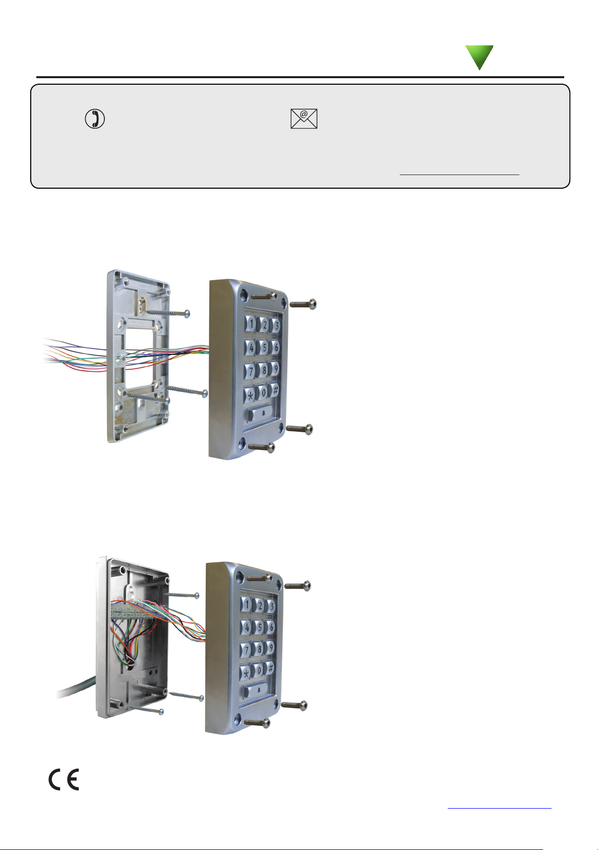
Fitting for a water resistant installation.
The assembly is waterproof (IPX7 rated) when
used with the mounting plate and all the cable
connections are made inside the building.
Paxton
Fitting to existing wiring
The alternative surface box contains a terminal strip
making it ideal for connection to existing wiring.
The declaration of conformity is available on request. Contact details are provided at: http://paxton.info/596
Page 2
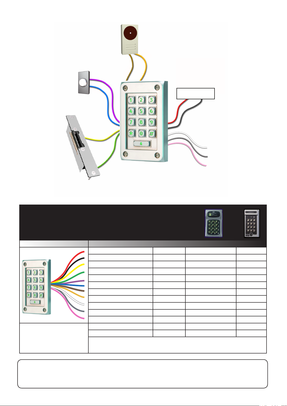
Wiring
Exit button
(push to make)
Exit
0V
V+
0V
V+
Bell
0V
Lock control is provided by both a powered
lock output and also a voltage free relay.
If the V+ lock wire (Yellow) or V+ bell wire
(Brown) are not connected they must be
terminated to avoid a short circuit.
Power supply
V+
0V
The combined current for all
outputs must not exceed 1A.
N.C.
COM
N.O.
Electric release
Wire outputs
Have you installed an ACT 10 keypad or Bewator K42?
If so, use this conversion chart to assist with the wiring change.
Dening any user code as a
duress code will change the
function of the Orange and
Brown wires to a duress alarm
output and will disable the bell
button on the keypad.
When using the relay output, it is not recommended to
use the 'Lock wire setting' in the 'fail open' mode.
Features
Power supply
0V
Lock V+
Lock 0V
Exit input
Exit 0V
Bell V+
Bell 0V
Relay (Default - N.C.)
Relay COM
Relay (Default - N.O.)
Duress Alarm V+
Duress - 0V
Features not available: Tamper, Door Contact, Multiple Doors, Timers, Interlock.
Paxton
Red
Black
Yellow
Green
Mauve
Blue
Brown
Orange
White
Grey
Pink
Brown
Orange
ACT10 Bewator K42
J4-1 +12V/24V
J4-2 -12V/24V
N/A
N/A
J2-3 Push button
J2-1 Inputs 0V
J3-2 Buzzer
J3-1 Outputs 0V
J4-3 N/C
J4-4 COM
J4-5 N/O
J3-3 OP3 Duress
J3-1 Outputs 0V
Terminal 1
Terminal 2
N/A
N/A
Terminal 6
Terminal 9
N/A
N/A
Terminal 5
Terminal 4
Terminal 3
N/A
N/A
Full System Reset
1. Power down the system. 3. The unit will beep/ash LED's 3 times a second.
2. Power the system up whilst holding down button 3. 4. Go to - Initialising a new system.
Page 3

Initialising a new system
Choose a 6 digit Programming Code and load this into the unit as follows:
The default user code is 1234 - the programming code must not include 1234 in the same order.
You can now set up the user codes and features using the programming chart.
Example: - Setting a user code to unlock the door under Normal conditions.
Enter 6 digit
Programming
Code
The unit will beep and the LED ashes faster
This box can be used to write down the Programming Code for future reference.
IMPORTANT: Do not set the Programming Code to 123456.
The door lock will release after 1234 and ignore any remaining numbers.
Enter 6 digit
Programming
Code
The default user code is now set to 1234
8
Hold for 3 secs
Ensure that this information is stored in a secure place.
Enter user code
4-8 digits
Re-enter 6 digit
Programming
Code
Re-enter
user code
4
Normal
START - Enter the 6 digit Programming Code and hold down a function key
for 3 seconds. - The unit beeps and the LED ashes faster.
Continue the key sequence to set the option - The keypad returns to operating mode.
X
2
2
2
2
Re-enter
user code
X
One code only
Fail locked
Beep on
OFF
OR
OR
OR
OR
OR
OR
OR
Multiple codes allowed
6
Fail open
6
Silent
6
ON
6
4
6
8
2
= Normal
= Toggle
= Duress
= Delete
Set a
user code
Door open time
(seconds)
Single or multiple
codes
Lock wire setting
Silent operation
20 wrong keystrokes
= 60 second lockout
8
Enter user code
4-8 digits
5
Enter time in seconds
(default = 07, max = 60)
2
1
3
4
Exit button
Change
Programming Code
Data Reset (except
Programming code)
7
6
9
2
Enter 6 digit
Programming
Code
Enter 6 digit
Programming
Code
Open door for
time in option 5
OR
6
Re-enter 6 digit
Programming
Code
9
Toggle door open
until pressed again or
toggle code entered
= default setting
= Hold down for 3 secs
Page 4

Technical Help
Here is the list of topics about this product that receive the most technical support enquiries.
We list them here to help you speed up the installation and trouble shooting process.
1 - Can I use a fail open release (e.g. Maglock)?
QBy default, the compact keypad is set to operate with a fail locked release by providing a voltage across the lock wire pair when
Qa valid entry is made. To use a fail open release, the lock wire setting needs to be changed (Program option 1).
2 - How do I integrate an entry phone system?
QThe output from the entry phone system is used to simulate the 'push' of an exit button for the Paxton equipment. No voltage
Qshould be directly applied to the exit wires (Blue / Mauve).
QMost phone systems provide a powered output pair to drive the door lock. This voltage must be used to drive an independent
Qrelay. The relay contacts must be 'normally open going closed' to mimic a 'push to make' exit button. The voltage free relay
Qcan then be connected directly across the exit wires.
3 - What are the keypad code types used for?
QNormal - Releases the door for the time period set in Option 5.
QToggle - Releases the lock until the code is entered for a second time.
QDuress - Releases the lock (as in Normal) but also energizes the bell output for 30 seconds.
QDelete - Used to remove a specic code that has already been entered in Multiple mode.
4 - Can I connect a compact with another Paxton control unit?
QThis cannot be done. Paxton Compact systems have the control electronics built in and no direct data output is provided.
QThe Switch2 and Net2 system use a different type of data input.
QNote: The compact system is designed to control the door unit on its own.
5- Can I have read in and read out on one door with two keypad units?
QYou cannot wire the lock outputs from two units in parallel to a common lock as they will both power the door lock
Qindependently and will not offer single point control. The power supply or keypads may also be damaged.
QWe therefore recommend using an independent power feed switched through the relay outputs (COM/N.O./N.C.) of the two
Qunits to provide the lock control required.
Features
Number of Codes
Code length
Door open time
Silent operation
Can be used with fail OPEN locks
Can be used with fail CLOSED locks
Exit button input
Door Contact input
Backlight
Electrical
Voltage DC
Voltage AC
Current
Maximum load output current
Dedicated lock output voltage
Dedicated lock output current
Relay switchable voltage
Relay switchable current
Alarm/bell output voltage
Alarm/bell output current
Cable length
Environment
Operating temperature
Waterproof
Dimensions
With mounting plate
With surface mount box
Specications
Min
1 50
4 digits 8 digits
Min
9V 24V
9V 12V
Min
-20 °C +55 °C
IPX7
Width
89 mm 143 mm
89 mm 143 mm
Max
60 secs 1 sec
Max
150 mA
1 A
1 A
24V
2 A
1 A
Max
Height Depth
Yes
Yes
Yes
Yes
No
Yes
Lock + bell
Follows supply voltage
Follows supply voltage
3 metres
Outdoor use
28 mm
40 mm
 Loading...