

Page 1
30/11/2011
Ins-30005 TOUCHLOCK K series keypad
Technical Support
01273 811011 support@paxton.co.uk
Technical help is available: Monday - Friday from 07:00 - 19:00 (GMT)
Documentation on all Paxton products can be found on our website - http://www.paxton.co.uk/
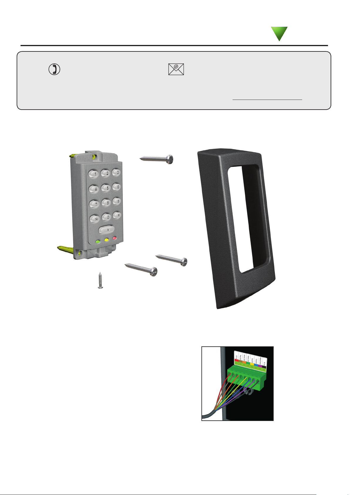
Fitting
Paxton
Saturday from 09:00 - 13:00 (GMT)
K75 Screw connector option
The unit should be mounted in conjunction with
an electrical backbox to achieve the required
clearance for the connector.
If an adaptor plate (310-750) is tted, the
mountings on the backbox can also be used.
Indoor use only
Cable extensions
Readers can be extended using Belden CR9540 10-core overall screened cable to a maximum of 100 metres.
Page 2
1
2 3
4 5 6
7 8 9
0 #
*
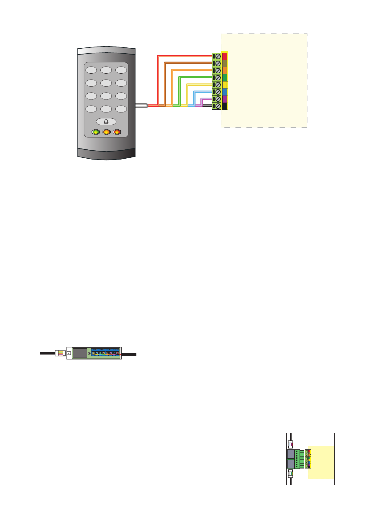
Wiring
Connection to a control
unit reader port
When using this keypad style with Net2, the software version used must be v3.21 or later.
WHITE labelled Net2 control units provide 5V at the Red terminal. The Red power wire for the
reader should therefore be directly connected to the 12V ACU terminal.
Switch2 controllers with WHITE labels are incompatible with these products. The keypads in the K and KP series,
can only be used with Switch2 controllers tted with YELLOW wiring labels.
Connection modules
Reader junction box (325-020)
This module can be used to provide a
connection point for the reader RJ45 plug.
The terminals on the module are then wired
colour for colour to the controller.
Alternatively, the reader can be wired directly
into the screw terminals of the control unit by
rst cutting off the RJ45 plug and stripping
back the wires in the cable.
Reader port module (325-030)
This module may be purchased separately to speed up
the installation and replacement of readers.
The reader port module is designed to convert the
standard reader ports on Switch2 and Net2 controllers
to accept one or two RJ45 connections. Pull off the
screw terminal block from the reader port and simply
replace it with this module.
Further information on how to purchase Installer Tools is available at:
http://paxton.info/841
Page 3

Technical Help
Here is the list of topics about this product that receive the most technical support enquiries.
We list them here to help you speed up the installation and trouble shooting process.
1 - Net2 - Bell function.
QPressing the bell button on the keypad will result in Relay 2 being energised for 1 second. A bell sounder can be
Qcontrolled by wiring one of the bell feeds across COM / NO on the relay.
2 - Readers/keypads not working.
Q- Software settings - Conrm that the settings of the reader or keypad are correct.
Q- Connections - Check the wiring of the connectors. Where possible, test this reader on the other port.
Q- Extended Cable - Belden 9540 should be used. (100 m maximum) Twisted pair alarm cable should
Q not be used. To conrm that an extended cable is not at fault, wire the reader direct into the reader port.
Q- Supply voltage - Conrm that the voltage is within specication. (see table)
Q- User token - Conrm that the user token used for testing is OK by presenting it to a known working reader.
Q- Interference - Conrm whether the reader works when tested 'in hand' and not mounted on the wall. Ensure
Q that readers are not mounted back to back or there is no interference from other local RF devices.
3 - Readers/keypads - Extending cable.
QOnly Belden CR9538 / 9540 can be used for cable extensions. CR9538 8 core up to 25 m, CR9540 10 core for
Q25-100 m (maximum extension). With CR9540, the two additional cores should be used to double up for power.
4 - Switch2 - Initialising with 2 keypads.
QEither Keypad can be used to initialise the controller. Connect all wires in parallel, colour for colour.
5 - Switch2 (White label) & Touchlock Switch Control (922-177).
QThis keypad style does NOT work with these control units.
6 - Duress Codes.
QNet2 - Duress codes cannot be programmed into Net2.
QSwitch2 - These systems can accept Duress codes.
7 - Net2 - Replacing an old style keypad. (ACU Keypad port).
QWhen using this keypad with Net2, the software version used must be V3.21 or later and the keypad must be
Qwired into the reader port.
Suitability
Security-sensitive doors
Mounted on metal surface
Wet environments
Readers mounted together
Page 4

Keypad bezels
Additional bezels are available in black, white, grey, blue and silver. Registered installers can order these free
of charge by logging onto the secure installer extranet: http://paxton.info/1035 or if you are not a registered
installer please call us on: 01273 811011 for more information.
Specications
Electrical
Voltage
Current
Clock and data bit period
Backlight
Environment
Operating temperatures - all items
Waterproof - Fixed cable
Waterproof - K75 - Screw connection
Cable length
Dimensions
K38 38 mm 78 mm
K50 50 mm 100 mm
K75 75 mm 143 mm
This product is not suitable for retail sale. All warranties are invalid if this product is not installed by a competent person.
Min
8V DC 14V DC
Min
- 35 °C
IPX7
Width
Max
100 mA
Max
+ 66 °C
Height
600 µs
Yes
Outdoor use
Indoor use
5 metres
Depth
13 mm
15 mm
16 mm
The declaration of conformity is available on request. Contact details are provided at: http://paxton.info/596
 Loading...