

Page 1
TOUCHLOCK keypad Stainless Steel (485-374)
Contents of kit
TOUCHLOCK keypad Stainless Steel
TOUCHLOCK keypad Stainless Steel installation instructions
TOUCHLOCK keypad Stainless Steel mounting template
220 ohm resistor
Fitting kit
Suitability
Products
The TOUCHLOCK keypad is suitable for use with the Switch2 control unit (405-321) and the PC based Net2
control unit (489-334).
Environment
The keypad will operate between –20
and external use.
Where to use the TOUCHLOCK keypad
YES NO Reason why not
o
C and +70oC. It is rated at IPX7 and so is suitable for both internal
Low to high use doors Completely vandal proof Keypad is exposed
Inside and outside
No need to shelter from the elements
Narrow door frames
Architecturally sensitive installations
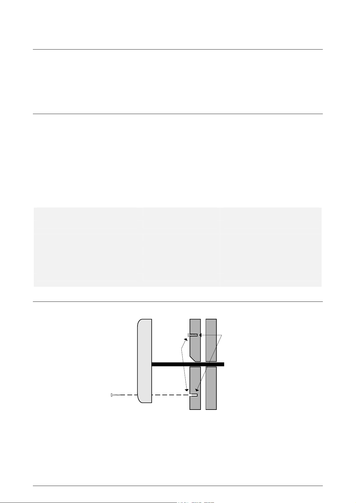
Fitting
TOUCHLOCK
keypad
stainless steel
8 X 1"
Wall plugs
Cable
• Using the template provided with the keypad, drill holes for the two screws and the cable.
• Extend the top of the cable hole to allow the keypad to slide down during fitting.
• Insert the raw plugs and screw the top 8 X 1” in only. Leave a gap of approximately 2mm between the
screw head and the face of the wall. Try the keypad on the screws and adjust as required.
• Once a good fit has been achieved, thread the cable through the wall and locate the keypad. Lock it into
place with the locking screw at the bottom. If being installed into a vandal risk area, a tamper resistant
security screw can be used.
INS-006 Date code: 201200
Page 2
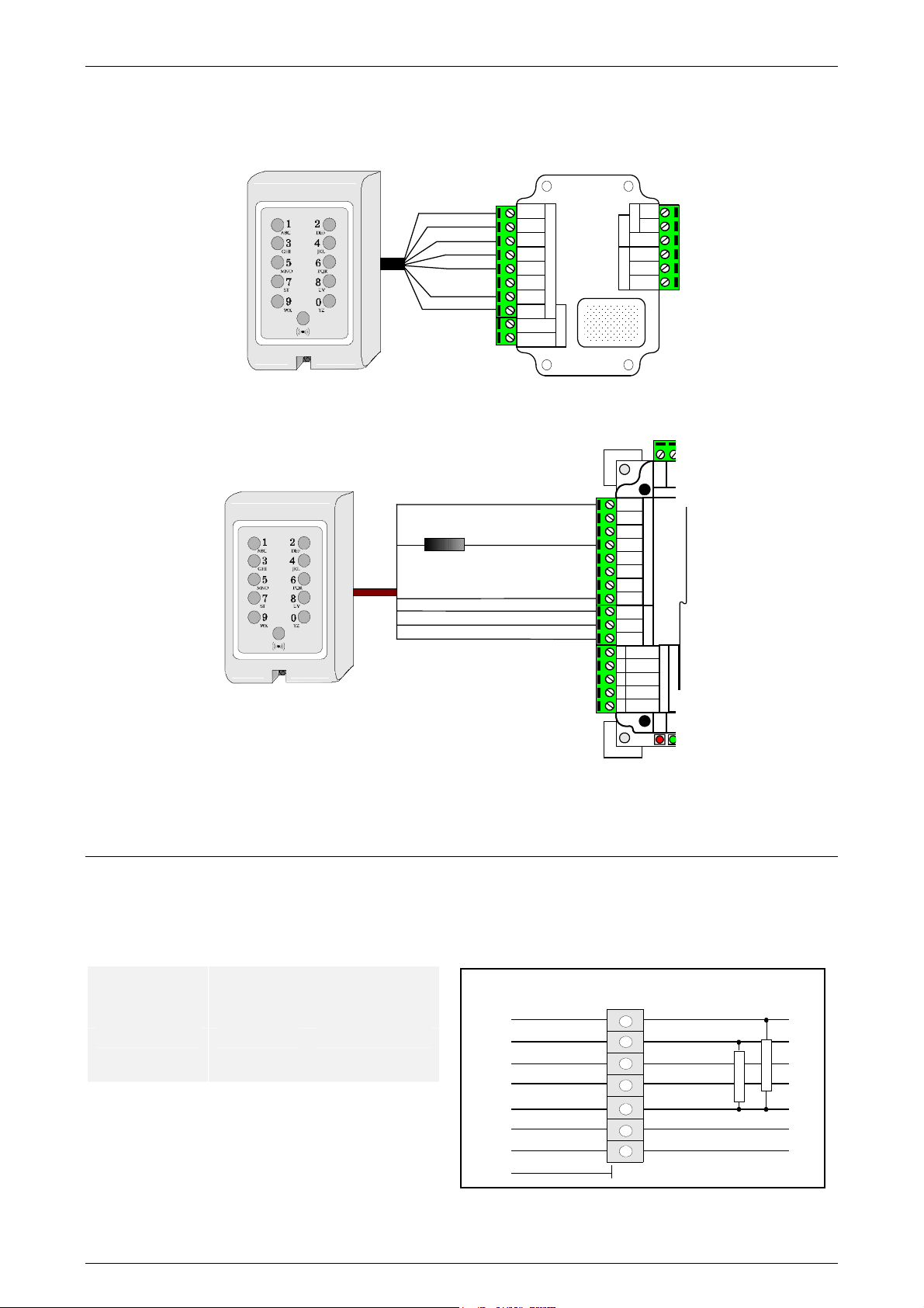
Wiring
TOUCHLOCK keypads are supplied with 3m of cable. The colours of the cable cores correspond to the
labelling on the Switch2/Net2 ACU.
Red(5v)
Brown
Orange
Green
Yellow
* Yellow
Black
Red
Brown
Orange
Green
Yellow
Blue
Mauve
Black
Contact
Exit
Card reader or keypad
S
witch
Control
Inputs
2
unit
Q.C. Label
Attach
here
Bell
Alarm
12v
PowerDoor relay
0v
N.C.
N.O.
Com
To save space on the board, a keypad wired to the Net2 ACU shares power and LED terminals with the
reader.
Yellow
Orange
Green (green LED)
*
Blk/Wht (0V)
Brown (load)
Yellow (data)
Orange (clock)
* 220 Ohm resistor
supplied in the keypad fitting kit
Red (5V)
Red
Brown
Orange
Green
Yellow
Blue
Mauve
Blk/Wht
Brown
Yellow
Orange
Screen
5
White/Green
4
Green
3
2
White/Orange
1
Orange
Reader 1 Keypad 1
Keypad 2
CAT5 cable colours
Network
Rx
Tx
Connecting 2 keypads
If 2 keypads are to be connected to Switch2 they should be wired in parallel but the Yellow wire from the
second keypad connects into the Mauve terminal. If 2 keypads are to be connected to Net2 the second
keypad connects to the keypad 2 slot provided.
Cable Extensions
The type of cable used to extend this distance will effect the maximum distance the keypad can be extended.
All distances are assuming that the keypad is wired according to our instructions.
ACU used
Net2 ACU 30M 30M
Switch2 ACU 30M 30M
Be sure, when extending the cable distance beyond 3M, to keep the colours the same throughout the run.
Beyond 10M pull up resistors must be fitted as shown above!
Maximum distance from ACU
CR9538 CR9540
Brown
Orange
Yellow
Green
Red
From Keypad
Black & White
Purple
Blue
Junction
box
Not connected
Brown
Orange
Yellow
Green
Red & Blue
Black & White
Purple
To control unit
INS-006 Date code: 201200
 Loading...