

Page 1

ver. 1.32-01
TC 204 Heating Controller
The TC204 is a multi-purpose heating controller with built-in programs for different types of heating systems.
General Data
Power requirement 24 volts ac, 25 va
Inputs 3 10k ohm ntc thermistors
1 digital
Outputs 3 digital
2 analog 0 - 10 volt dc
This manual covers outdoor reset of hot water heating systems using a mixing valve and a 3-point
floating actuator. For other applications see the expanded manual at www.paxtoncorp.com
Notes to the installer:
1. Program #1 - Outdoor reset control using a mixing valve, is the default program.
2. All defaults in program #1 will work in most cases.
3. Connect all sensors, the actuator wires and power supply. Set time & date (page 9)
and let the system stabilize, before making any program changes.
Nothing else needs to be done in most cases.
Wiring
The diagrams show ESBE #62E (Paxton VM62) & 92-2M (Paxton VM92) valve actuators . These are 3-wire
floating, 24 volt ac valve motors which fit ESBE 3-way & 4-way valves.
VM62 actuators are used with valve sizes 1/2” through 2”: VM 92 actuators are used with valve sizes 2 1/2” - 6”.
Actuators of this type have a common wire. Voltage applied between the common and one of the remaining wires
drives the valve open and voltage between the common the the remaining wire drives the valve closed. If no voltage is applied to either terminal the valve stays in place.
Other valves with different floating actuators may be used provided the voltage is 24 volts and the current draw
of the actuator does not exceed the capacity of the TC204 (25 VA). If these 2 conditions are not met the actuator
must be operated through intermediate relays.
Programs
There are eight programs in the TC204. This manual is for Program No.1 which is the default program.
Some not frequently used functions are not covered in this manual. Instructions for these as well as for all other
programs are available at:
www.paxtoncorp.com
Other programs provide outdoor reset by modulating valves that accept a 0 - 10 volt dc signal, outdoor reset by
direct boiler control, zone control without outdoor reset, and outdoor control of steam heating systems.
Program No. 1
Program 1 is Supply Water Temperature Control using a 3-point floating valve actuator. The control mode can be
Outdoor Reset with or without a room sensor, or direct control by room temperature only.
The supply temperature sensor must always be installed.
Outdoor reset is automatically initiated if the outdoor temperature sensor is installed.
Room temperature control is automatically initiated if the room temperature sensor is installed.
Additional functions are Pump Control, Auxiliary Output, and Return Water Low Limit (see page 8).
Temperature Sensors
The supply water and outdoor air temperature sensors are included with the TC204. A room temperature sensor
is optional. A room sensor is also built into the TC204, but to use it the TC204 must be installed in the controlled
space.
1
Page 2
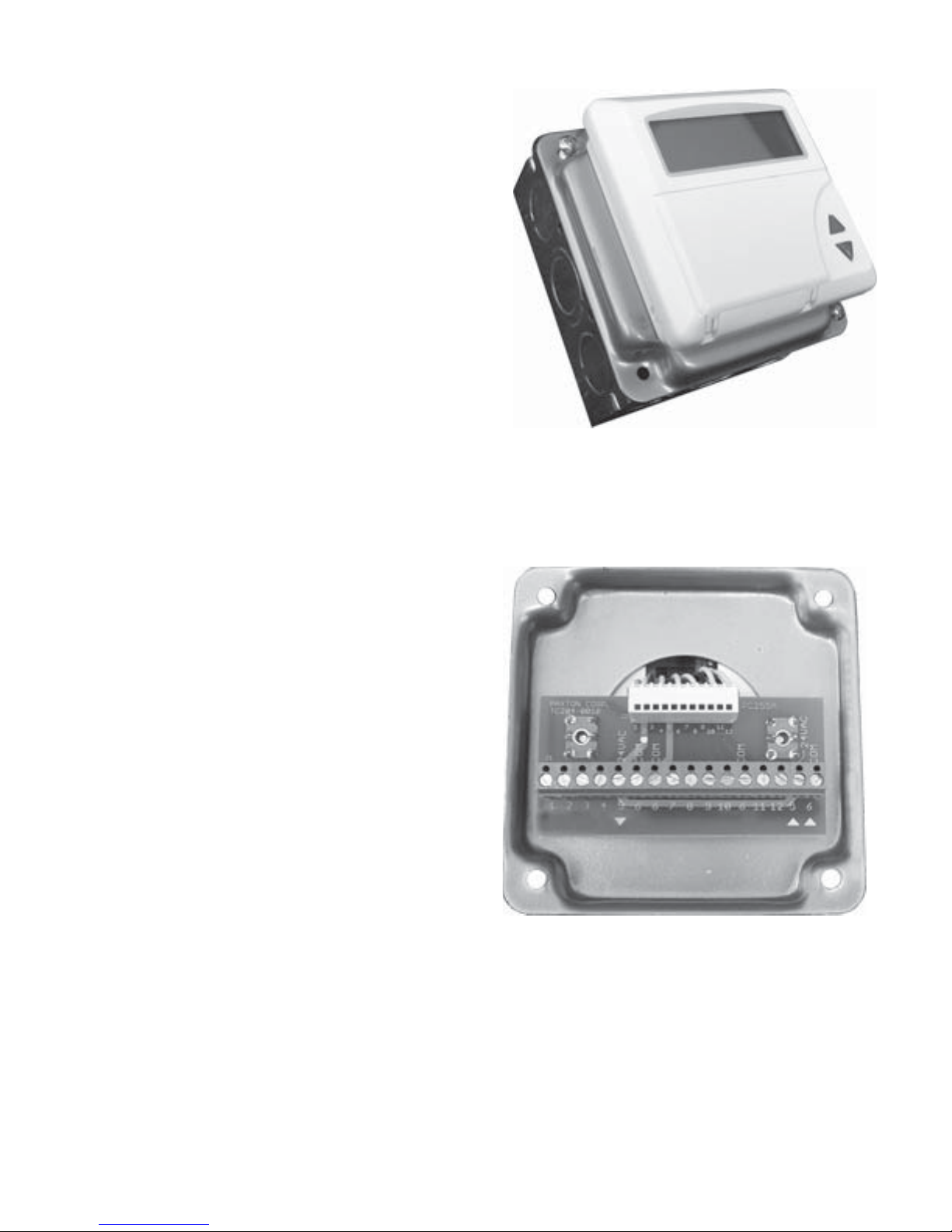
This comes in the package:
TC204 Controller mounted on a standard
4” x 4” electrical box
1 Outdoor Sensor
1 Supply Water Sensor
2 Cable Connectors (inside the electrical box)
1 Instruction Manual
Provided by installer:
120/24 Vac Transformer, 25 - 40 VA
Installation:
Remove the two screws in the corners of the 4” x 4” box
and lift off the cover. The controller is secured to this cover.
Set aside the 2 cable connectors located inside the box.
Install the box on a wall near the mixing valve or boiler,within
reach of the actuator cable. Or inside the mixing station
enclosure if there is space available.
Remove 1 or 2 knockouts and insert the cable connector(s).
Run the power supply, sensor, and output wires into the box.
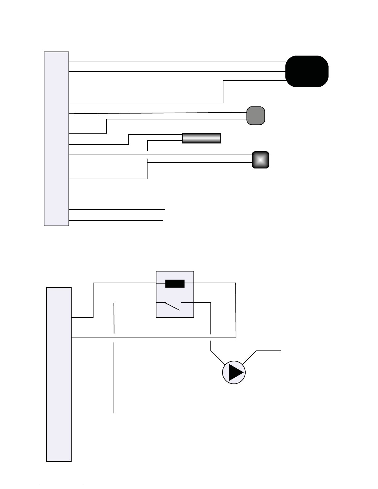
The TC204 is connected to an external terminal
board secured to the under-side of the 4” x 4”
cover. This simplifies field wiring as there is no
need to open the controller itself.
The controller is pre-programmed with defaults
that match most heating systems in the northern
States & Canada. Typically no other adjustments
are needed but are easy to do, following instructions in the operations manual.
Let the system stabilize before making
changes to control parameters.
Notes:
The TC 204 can be removed from the steel box cover and the external terminal board for
installation directly in an occupied space.
Loosen the connector on the circuit board and then the center screw under the lid of the controller.
Pry off the front of the controller and remove the two screws holding the terminal board.
For wiring of other applications, such as direct control of boilers in sequence, see the manuals on
our website www.paxtoncorp.com.
2
Page 3
Outdoor Reset Control with
the VM62 Actuator.
Black
(counterclockwise)
1
10
11
12
2
3
4
Brown
(Clockwise)
Blue
(Common)
VM62 Actuator
5
6
6
7
Supply Water Sensor
Room or Return Sensor
(Optional)
8
9
6
5
6
24 Volts ac Power
25 va minimum
If the valve turns in the wrong
direction, reverse the brown &
black wires on the VM62 actuator
Sensor wires can be lengthened
with thermostat wire to maximum
250 feet.
Outdoor Sensor
10
11
12
Relay 24 vac coil
spst no
1
2
3
4
5
6
N
6
7
8
9
Pump
6
Line
Pump Control
5
6
3
Page 4
1
2
3
4
5
6
6
7
8
9
10
6
11
12
5
6
N L1 L1
VM92 Actuators
Note:
The 2 terminals marked L1 are not the
same.
The left one drives the actuator clockwise and the right one drives the actuator
counter-clockwise.
Output 2 on the TC204 increases heat.
10
11
12
1
2
3
4
5
6
6
7
8
9
6
5
6
1. Output to actuator – Less Heat
2. Output to actuator – More Heat
3. Pump start/stop (use external relay)
4. input for remote operation
5. Output to actuator 24 Vac
6. Common
6. Common
7. Return water or room sensor (optional)
8. Supply water sensor (must be used)
9. Outdoor sensor
10. Auxiliary output 10 Vdc
6. Common
11. ModBus A+ communication
12. ModBus B- communication
5. 24 Vac Power supply (hot side)
6. 24 Vac Power supply (common)
Always use this pair of terminals for the power input.
4
Page 5

TC204 Programming Instructions
General
There are 7 buttons. They are:
Right & Left Step through values in a menu
A Set the Timer
B Select temperatures
C Inactive in Program 1
Up & Down Arrows
Clock and change values
The time and date are set in the BASE menu. The clock stops
after about 3 days without power and must be reset.
All other programming is permanent unless it is deliberately changed.
Readouts
Temperature readouts can be in either Fahrenheit or Celsius.
Fahrenheit is the default
Programming
The TC204 can be programmed before installation.
This requires that power and the sensors are temporarily connected.
A missing sensorʼs function can be programmed.
Some functions appear only when the control type is set.
The TC204 is programmed by setting the value of various functions. A menu is a group of several functions.
To select a function
press
Use to scroll to the menu with the function you want.
Once you select a value in a line, it is permanently set when you press
until the word MENU is flashing.
Scroll through menus
(or ).
You leave programming by pressing and holding the key.
Outdoor Reset Programming: Modulating a VM62 or VM92 Actuator
Function Menu
Outdoor Cut-off Temperature 9
Hight & Low Limits 6
Outdoor Reset Curve 8
Pump Control 11
Press
The wrench symbol appears and the word MENU flashes.
Go to Menu 9
Scroll to MENU 9 with the
It should read 1. If it doesnʼt, select 1 with the
Press
Valve Running Time
P.Time 10 - 510 seconds Default 120
This is the time it takes the actuator move the valve through its full stroke. From fully open to fully closed is
120 seconds for the model 62 actuator, so leave this setting as the default value. This program will operate most
3-point floating actuators. If you use a different actuator set this number to match the actuator speed.
Output Selection
O P1-3 - This function is inactive in programs 1. A dash ( - ) indicates an inactive mode.
TYPE - Inactive in this program
keys and then use the key to scroll to SELpr.
keys.
5
Page 6

Menu 9
Valve Exercise
MOT. 0 - 30 days Default 0
This line exercises the valve to keep it from sticking after a long period of inactivity. The valve periodically opens
at 1:00 am and closes 3 minutes later. The line is inactive if it is set at “0”; otherwise the number is how often the
event occurs: “1” for every day, “7” for once a week, or “10” for every 10 days.
Invert Outputs
INV. 0 or 1 Default 0
In program 1 this line inverts outputs 1 & 2 . 0 means the relay closes on demand; 1 means the relay opens.
Limits
LIM.L & LIMH These are inactive in this program.
Outdoor Cutoff Temperature
CUT.O -40º F to 122º F Default 86º F
This is the outside temperature when the valve closes completely. Above this temperature the valve wonʼt open
except the valve exercise function (MOT, above) does function.
Duty Rotation (boilers in sequence)
DR Inactive in this program.
Go to Menu 6 REGUL
Minimum Water Temperature
MIN W 41º F - 203º F Default 75º F (24º C)
When you set the minimum water temperature the supply water temperature does not go below the setting until
the outdoor temperature is above the cutoff temperature. Then the valve closes.
MAXW 41º F - 203º F Default 140º F (60º C)
When you set the maximum temperature, the supply temperature never rises above the setting.
Proportional Band
P.W 0.5º C - 99.5º C Default 60º C Leave at the default setting.
Integral Time
I.W 0 - 50 minutes Default 0.5 min Leave at the default setting.
Room Proportional Band
P.R 0.5 - 50º C Default 2.0º C Leave at the default setting.
Room integral Time
I.R 0.0 to 99.5 minutes. Default 30 min Leave at the default setting.
Temperature Deviation Limit
≠P 0.0 to 5.0 Leave at the default setting.
This function only works when you change the room temperature setting.
MAX- 0º - 90º C Default 80º Leave at the default setting.
MAX+ 0º - 90º C Default 80º Leave at the default setting.
These are the minimum and maximum amount the room temperature can cause the supply water temperature to
deviate from the outdoor reset curve. If there is no outdoor sensor or room temperature sensor these lines have
no meaning. If no deviation is permitted the effect is the same as having no room sensor.
VENT 0 or 1
This setting prevents open windows or doors from having too much effect on the supply water temperature.
When active, it only permits the water temperature to rise 10º C (18º F) above the calculated value of the reset
curve. It disables itself after 1 hour.
6
Page 7

Go to Menu 8 CURVE
There are 3 adjustable values in this menu.
Curve Design
When you use a room sensor the reset curve is self adjusting. You need this section only if you donʼt use a room
sensor and the default curve does not work for your region.
- 10C1 32º F - 248º F Default 140º F
Supply water temperature at 14º F (- 10º C) outside temperature
+10C1 32º F - 248º F Default 86º F
Supply water temperature at 50º F (+10º C) outside temperature
The sample reset schedule shown in the chart is the default. To set +10C1 (50º F) & -10C1 (14º F) select the
water temperature you want at those outside temperature on the vertical F scale.
Suggested Initial Settings
Leave +10C1 at 86º. At 50ºF outside the supply temperature will be 86º F.
Set -10C1 so that at the outside design temperature in your area the supply temperature will be near the maximum temperature allowed in your system.
200º
190º
180º
170º
160º
150º
140º
130º
120º
110º
100º
90º
80º
70º
Supply Water Temperature
F
60º F 50º F 40º F 30º F 20º F 10º F 0º F
10º C -10º C
Outdoor Temperature
14
-10º F -20º F
Adjustments
Building is always cold Raise both settings
Building is always warm Lower both settings
Building gets colder as it gets colder outside Raise -10C setting
Building gets warmer as it gets colder outside Lower -10C setting
Automatic Curve Adjustment
AUTO 1 or 0 Default 1
When you use a room sensor this should be set at 1. 0 means the curve doesnʼt adapt.
Set it at 0 if there is no room sensor.
Cout1 Calculated Value
All other Menu 8 items are inactive.
7
Page 8

Reset Curve Summary
Function Menu Line
Outdoor Cut-Off Temperature 9 CUT.O
Minimum Supply Temperature 6 MIN W
Maximum Supply Temperature 6 MAX W
Supply Temperature at 14º F 8 -10C1
Supply Temperature at 50º F 8 +10C1
220º
200º
180º
160º
140º
120º
100º
80º
Supply Water Temperature
Menu 11 Pump Control
Pump control is optional. If used, go to Menu 11.
Menu 11 PUMP
SELECT 0 or 1 Default is 0
1 means pump control is active: 0 means there is no pump control.
LIM-0 32º F - 140º F Default 68º F
When the supply water temperature set point is below this setting the pump stops.
LIM-1 32º F - 68º F Default 64º F
Below this outside temperature the pump runs regardless of the setting in LIM-0.
MOT. 0 - 30 Days Default 7 days
The pump can run for 3 minutes at night, without regard to the settings in LIM-0 & LIM-1 above. The purpose
is to prevent seals from drying out. The intervals can be from 1 - 30 days apart. 0 means this line is inactive.
INV 0 or 1 Default 0
The output to the pump can be set to close (0) or open (1) on demand for the pump to run.
Return Water Control
Menu 7 RET.R
SELECT 0 or 1
Set this to 1 for return water control. This function sets a minimum boiler return water temperature which
overrides supply water temperature control until the minimum return temperature is reached.
This function does not work properly in all piping confi gurations (see piping schematics).
MIN 35º C - 60º C (= 95º F - 140º F)
This is the minimum acceptable boiler return water temperature.
P.RET 0.5 - 99.5 degrees
I.RET 0.5 - 99.5 minutes
These are the proportional band and integral time for the return water temperature. Leave default settings.
MIN W
60 50 40 30 20 10 0
Outdoor Temperature
+10C1
CUT.O
-10C1
14
MAX W
-10 -20 -30
8
Page 9

Setting Room Temperatures
Temperatures can be set with either the B key or in the BASE menu.
Menu 1 BASE
Press the key. You should see:
TIMER Use this line to set the timer. Press the
DAY1 NITE1 SAVE1 These are room settings for the day, night, and long term setback mode. Even if you
are not using room sensors, set these values. From the difference between the day & night settings the TC204
calculates how much it should set the reset schedule back at night.
If you are not using night setback, set them all at the same value.
Display Temperatures
Menu 1 Base
R1 Readout of room temperature
OUTD Readout of outdoor temperature
O.MIN Lowest outdoor temperature since the last time this value was reset.
WAT. Supply water temperature
WAT2 Return water temperature
If the sensor is not connected, the value, and in some cases, the symbol does not appear.
Setting the Clock
Menu 1 BASE
Use the
key to scroll to a line for time that looks like this:
key again.
WED
Use the UP or DOWN key to make a value flash; change it with the keys. Scroll to the next value with the
through the menu with the key.
You can use 12 hour time or 24 hour military time. Make the selection in Menu 12. Also, you can set changeover
between standard time and daylight savings time in menu 12.
The next line for date looks like this:
JAN.
Use the UP or DOWN key to make a value flash and change it with the keys. Scroll to the next value with
the Key and set it with the Keys.
To select the menus, use the
When you get to the value you want to set, make it flash with the keys and then change it with the
keys. After you make the change, press again to move to the next value.
02:35
key, & change it with the keys. Use the key until all values stop flashing. You can scroll backwards
10.04
Two dots between hr:min mean am, three dots pm
(day.year)
keys. When you get to the menu you want, step through it with the keys.
9
Page 10

Setting Times
Times are set with a weekly program in which the Day, Night, and Economy cycles begin at set times on
programmed days of the week. Optimized warm-up for the day cycle is also set in the Weekly Program.
Date Programs, in which a cycle is programmed to begin and end on specific dates and hours, override the
Weekly Program.
Weekly Program
Menu 2 W.PR.
WPno 1 or 2
There are two weekly programs. The Weekly Program set in this line is the active one for Day, Night, and
economy modes.
The Weekly Program for the auxiliary output is selected in the auxiliary output menu. The Weekly Program can
be the same for both applications.
Set values in both weekly programs by setting this line for one program, filling it in, and then resetting this line to
the other program and filling it in. Remember to reset this line to the Weekly Program you want active for day/
night programming.
Each Weekly program has 6 events that can be filled in. The data for each event is the time of day, days of the
week, and Day, Night, or Economy mode.
Times can be set at ten minute intervals. In 12 hour time PM is indicated by 3 dots between hours & minutes.
Days of the week are at the lower left of the screen in a row of 7 dots or vertical lines. Monday is day 1 and
Sunday is day 7. A vertical line means initiate a cycle on that day at the time shown.
The event number, 1 - 6, precedes the day indicator.
The symbol at the upper left of the screen shows the cycle that is going to start.
The Sun symbol indicates Day mode.
The Moon symbol indicates Night mode.
Both symbols together indicate economy mode.
When the control is running, the symbols show which mode it is in. If the symbol is flashing, the timer is running.
For example, This screen shows that event
#1 initiates a Day cycle Monday through
Saturday at 7:00 am.
This screen shows that event #2 initiates
a Night cycle Monday through Friday at
5:00 PM.
This screen shows that event #3 initiates a
Night cycle Saturday afternoon at 1:00 PM.
Step through the event with the RIGHT key and change the flashing value with the keys. When youʼre
.
done with an event and nothing is flashing, you advance to the next event with the key.
When you are using a room sensor, set the times for day cycles to the time of occupancy; do not allow for
warm-up because this is done with optimization. (next line)
1
2
3
10
.
..
7:00
5:00
.
1:00
.
Page 11

Optimization
Menu 2 W.PR
OPT1 0 - 40 Default 20 Skip this line initially.
The colder it is outside and/or the further the room temperature is below set point the sooner the controller will
start the warm-up cycle. The number in this line is a constant in the equation the TC204 uses to calculate the
warm-up time. If the building warms up too soon, lower it to 15; if the building isnʼt warm soon enough, increase
this number to 25. If you set this line to 0 there is no warm-up cycle at all.
Calibration
Menu 12 CAL.
You can calibrate the temperature sensors used in the TC204.
R1 -9.5 to 9.5 degrees
Room Temperature Sensor Calibration
R2 -9.5 to 9.5 degrees
Second Room Temperature (if used)
OUTD -9.5 to 9.5 degrees
Outdoor Temperature Sensor Calibration.
SEC/D -9.9 to 9.9 seconds per day
If the clock runs fast or slow it can be adjusted here. If it is slow add a positive adjustment. If the clock gains one
minute per month, make the adjustment -2.0.
Daylight Savings Time
Menu 12 CAL
SUM Month 1 - 12 Day 1 - 31
Begin Daylight Savings Time. The first pair of digits is the month and the second is the day of the month.
The clock will move forward one hour at 2:00 am on the date you set.
WIN Month 1 - 12 Day 1 - 31
End Daylight Savings Time. Set it the same way as SUM above. If you donʼt want daylight savings time set both
SUM & WIN to 0000.
Time
Menu 12 CAL
24h 0 or 1 Default 0 (12 hour time)
Set this to 1 if you want 24 hour (military) time, 0 for 12 hour time. In 12 hour time P.M. shows as 3 dots between
the hours and minutes.
Temperature Scale
SEL.ºF 0 or 1 Default 1 (F)
Set this to 1 if you want readouts in Fahrenheit. Not all temperatures can be set or read in F.
O.RES 0 or 1
The readout of the minimum outdoor temperature can be reset manually or automatically. If you want the readout
to reset automatically every day set this line to 1.
Date Program
Menu 3 D.PRO
You can set up to 4 events that override the weekly program. These can be set up to a year in advance. You
can, for example, set a long term setback for a vacation.
Extra Output
Menu 4 X.OUT
There is an extra output that can be activated by either time or outdoor temperature or both.
Logging Measured Values
Menu 5 LOG
You can keep a log of up to 96 values of the outdoor temperature or the supply water temperature or the room
temperature at intervals up to 1 hour apart.
11
Page 12

The menus are:
BASE 1 Set the Date, Time, Temperatures, and Timer function. Readouts
W.PR. 2 Weekly Program There are 6 time periods that can be set to begin a day, night,
or economy period. Each time can be set to begin on any day
or combination of days of the week.
D.PRO 3 Date Program There are 8 dates that can be set so that four different day, night,
or economy periods can be set to begin and end in advance.
A date setting overrides a weekly setting.
X.OUT 4 Extra Output This is an output that can be activated by temperature and/or time.
LOG 5 Log Values Running log of the outdoor temperature (or room temperature if it
is connected) for up to 96 events at intervals of up to 255 minutes.
REGUL 6 Control parameters Minimum & maximum supply temperatures, proportional bands and
integral times
RET.R 7 Return Sets the minimum return water temperature
CURVE 8 Curve selection Select the outdoor curve.
RET.R 9 Outputs Control type, outdoor cutoff temperature
INPUt 10 Inputs External contact function, internal sensor
PUMP 11 Pump Control The pump can be controlled by outdoor or supply water temperature.
CAL 12 Calibration Adjustment of the sensors to compensate for small errors in the sensor
or to compensate for the length of wire to the sensor. Adjust the clock
speed if it is running fast or slow, set the beginning and end of
daylight savings time, and set the clock for 12 or 24 hour time.
Set temperatures in Fahrenheit or Celsius.
BUT.F 13 Button Functions Security, locking, limits on settings, display
Test 14 Test Manually operate outputs, simulate temperatures, set security code
TYPE 15 TYPE This displays data about this particular controller. There are no
programmable functions.
KOMM 16 Communication ModBus
12
 Loading...